shipmodel
-
Posts
941 -
Joined
-
Last visited
Content Type
Profiles
Forums
Gallery
Events
Everything posted by shipmodel
-
 Hi Vaddoc - Unfortunately not. The amount of additional work involved would have increased the fee to a point where the client would simply junk the model. I have a particular fondness for the bone and ivory models and I didn't want that to happen, so we reached a compromise. I will do what can be done without stripping it to the sticks and starting again, which may well be a solution for the next generation of ship model restorers, if there are any. Dan
- 95 replies
-
- 5
-

-

-
- POW
- Bone model
- (and 2 more)
-
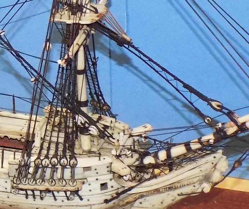
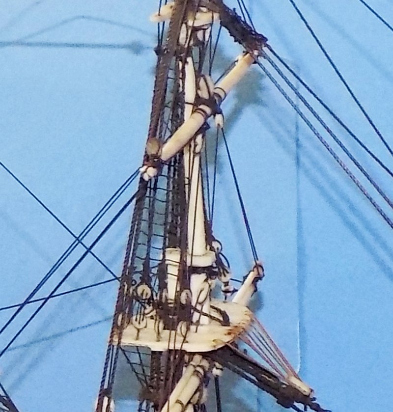
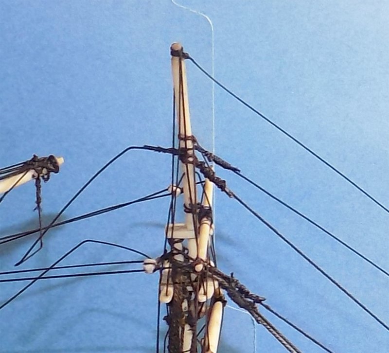
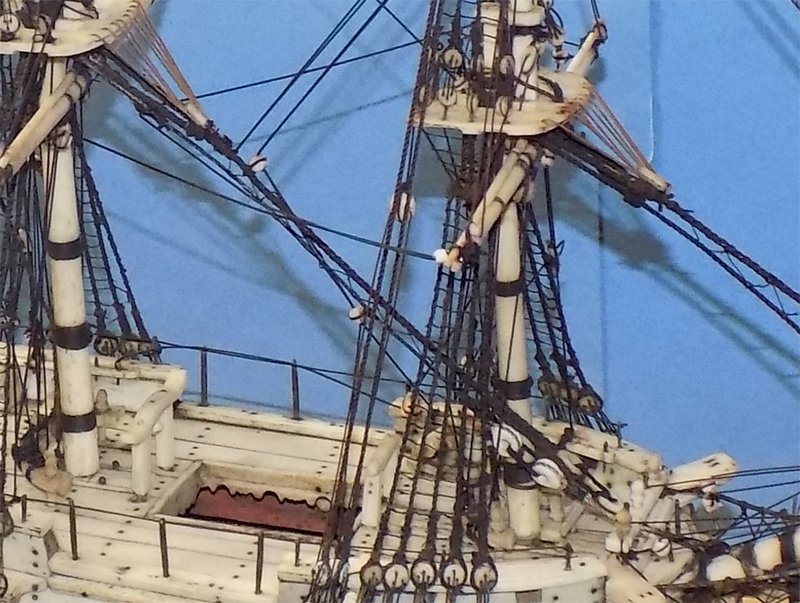
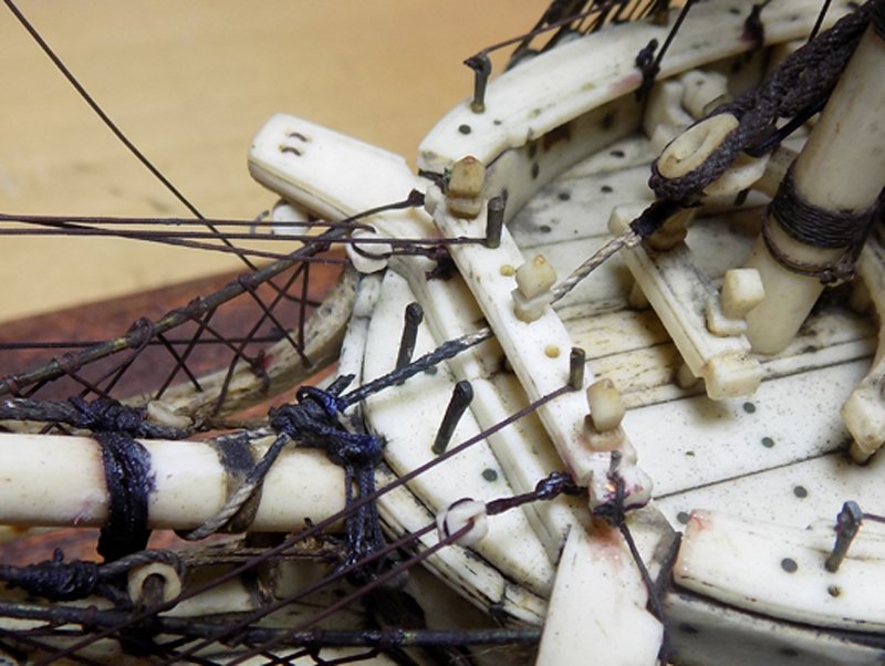
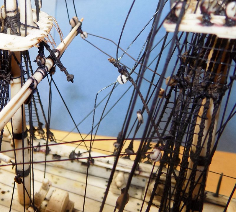
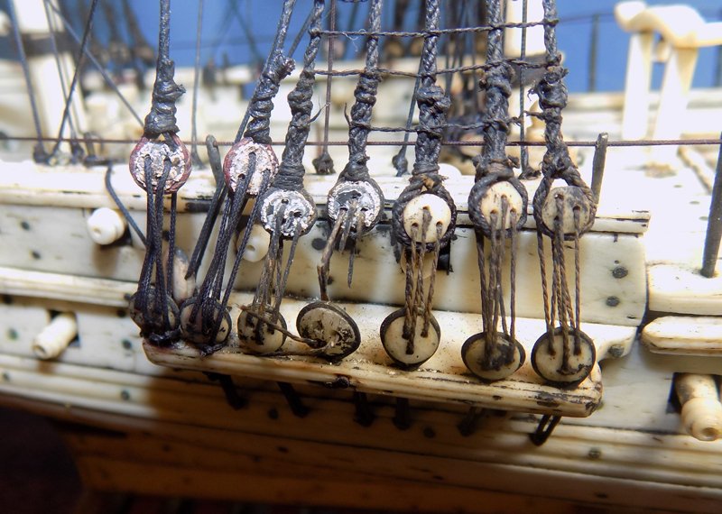
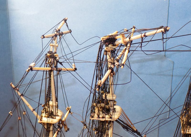
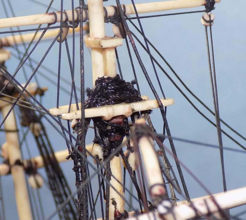
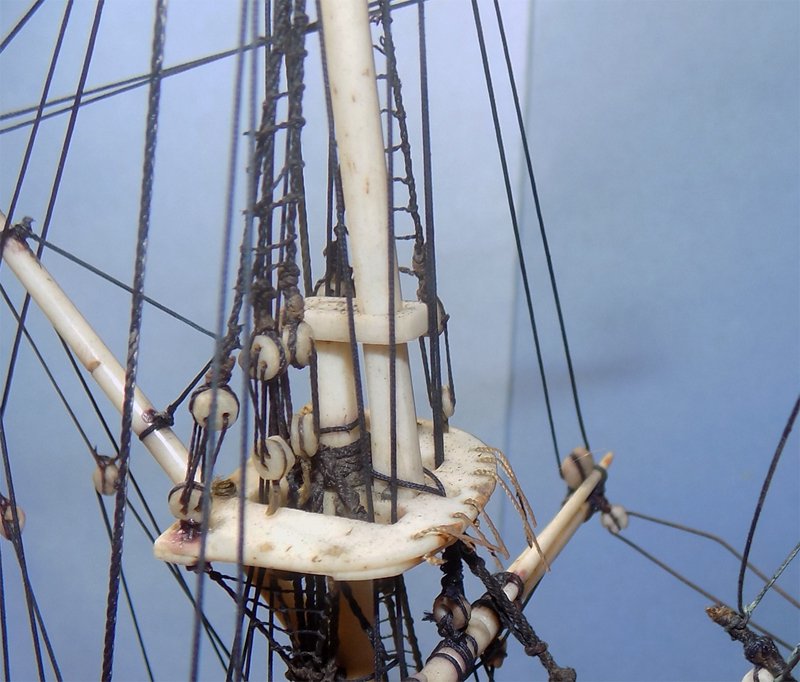
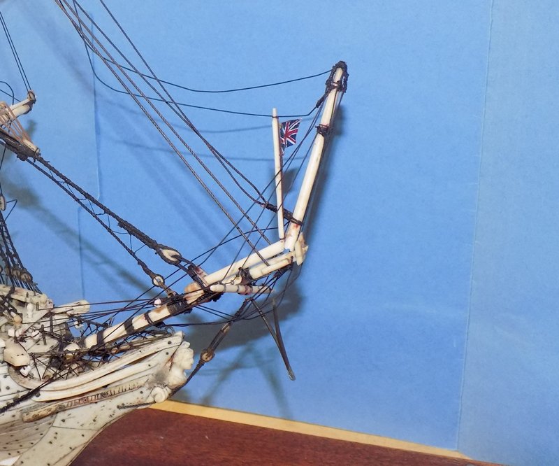
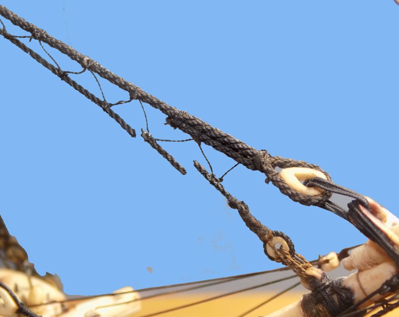
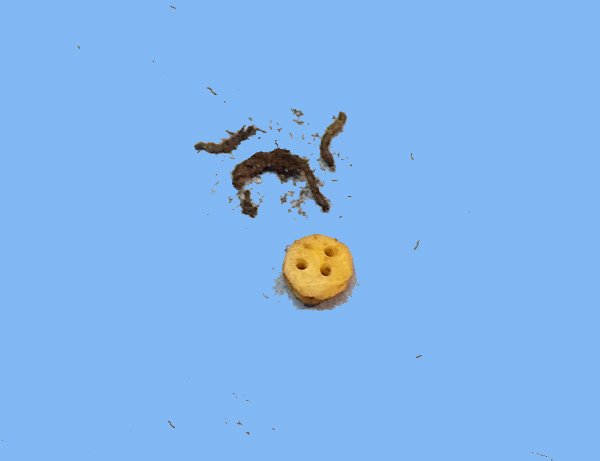
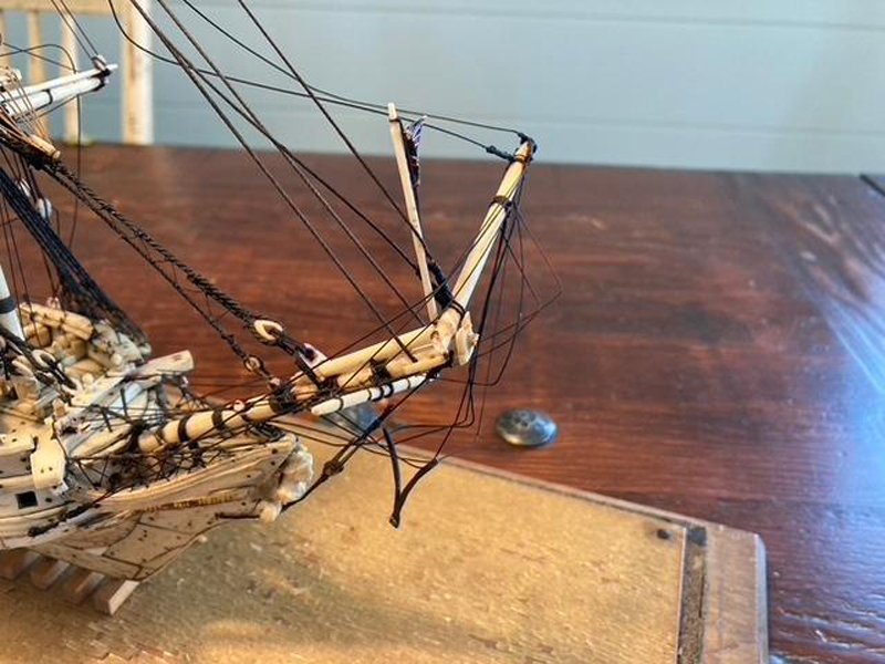
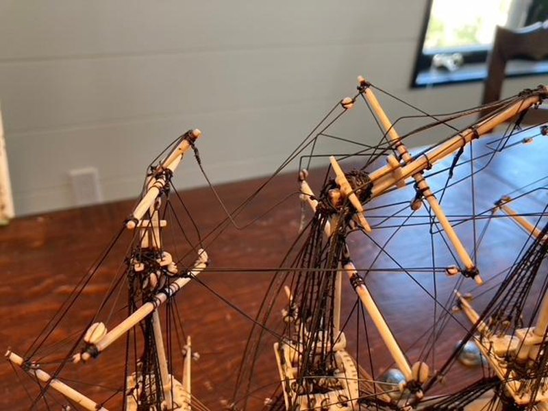
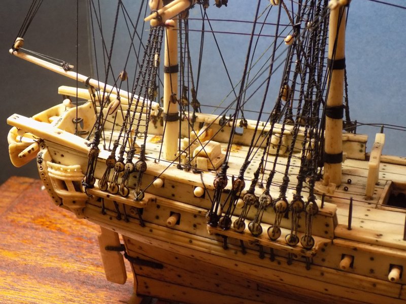
Hi again to all, and thanks for the comments and interest in this restoration. After reviewing the hull I turned to the masts, spars and rigging. The news was both good and not so good. First, to get an idea of what the model was like when she was built, I examined the best of the remaining masts and rigging, the foremast. Here are some photos of the details and some of my conclusions. Of course there are lots more of both, but that would take too much time to relate here. The foremast is well-proportioned to the ship and has several bands of woolding as would be proper. The fore spar is hung on jeers although there is no parrell, just a simple sling. It carries stun’s’l booms on each end. The shrouds are well-proportioned to the mast and the ratlines are appropriately thin. They are spaced at 3mm intervals, which also seems right. The deadeyes are carved from bone, 3mm in diameter, and generally well rigged. The forestay and preventer are correctly sized, with bone hearts and collars. They are even snaked together. A crowsfoot is laced with brown line to a bone euphroe on the stay. The fore topmast looks correctly sized, as does the doubling. However the mast cap has a through tenon, which is English practice, which contrasts with the French deck bench noted in the last segment. The fore course yard and topsail yard are rigged with lifts and braces, but no sheets or sheet blocks. There are nicely done futtock shrouds and upper shrouds with ratlines. Although extremely small, the ratlines appear to be rigged with clove hitches. The t’gallant mast and spar are well done, as are the two bone crosstrees. Here can be seen some of the prior repairs. The lower topmast stays (the lowest ones in the photo) appear to be original. They show a lay to the line and are served and seized as they go around the doubling. The four other stays all have fairly crude ties and seizings, with stubs of the seizing line sticking out. A gentle feel of the various lines confirmed that the upper ones are smooth and new, rather than the older, original ones. The main stay is original, as is the preventer stay below it. They are rigged with a proper mouse and eye on each with fore topmast braces and blocks tied to them. However, the hearts and collars are damaged. The preventer stay collar has been replaced with a line of the wrong size, the wrong color, and which goes under the bow pinrail, causing it to kink. It is seized to the bowsprit with a very crude knot. The main stay heart and collar are missing entirely. The mizzen stay is also original but broken completely. The several lumps on it are probably evidence of prior repairs that were less than successful. The crowsfoot is completely torn and the euphroe detached. I was provided with it in a separate envelope. You can also see that the sling/parrell line that should run from the lower mizzen yard jeer to the mast is broken. I believe that there were several sets of repairs in the past. For example, here are the main lower shroud deadeyes. The forward three are completely original, with bone deadeyes, the upper ones properly turned in and the lanyards appropriately sized and laced. The aft four have had the upper deadeyes replaced with metal castings. I thought that the rough look to them was lead bloom, but it turned out to be only the paint used to try to match them to the original bone color (whew!). I believe that this was the earlier of the repairs, since the lanyards of the two on the shrouds match the original ones and are properly laced. I believe that the aft two on the backstays represent a second repair since the lanyards are different and are incorrectly laced and tied off below the lower deadeyes. I found the same situation at the main mast. The topmast shrouds and deadeyes appear to be original, but the backstays are a completely different quality of line. The lifts look original but the upper stays are replacements with crude siezings. Viewed from behind I could see that there was a huge mass of mounded lines around the head of the topmast. This was where the original backstays were simply cut loose, leaving some stubs of line that can still be seen. The replacements were looped over them and glued in place, making a mess that may have contributed to the break. Although the main topmast shrouds seem to have survived, the same was not true for the mizzen topmast shrouds. The break was offset to port, so those shrouds were not stressed. The starboard ones were not so lucky. The forward two parted company from the futtock shrouds at the level of the top. The aft one held on at the lower end, but broke at the masthead. As a result all of the ratlines between the second and third shrouds parted. In addition to these issues, a fair number of the rigging lines did not run to their proper blocks or tie off to proper locations. For example, the main yard brace is misplaced, since it should run to the stern where there is an eyebolt and boomkin, but just ties off amidships. This and other evidence convinced me that at least one of the restorers did not know how a ship was rigged. After long discussion with the client about whether the model was worth the cost of restoration, he decided to go forward. We decided on a cost based on leaving as much of the current rigging, right or wrong, in place, but replacing what was needed and cleaning up the rest. With this understanding I very gently started to wiggle the broken pieces to see what could be retained and what had to be removed to get the pieces back into proper orientation. At the bow the jib boom could be gently manipulated to get the heel of the break to meet the head of the lower piece, but it would not straighten out. Several of the lines had shrunk and prevented it. I found that the shrunken lines were not original, but were part of some of the prior repairs. I believe that the glass cover had created a greenhouse effect that ‘cooked’ the lines over time and shortened them enough that they may have actually broken the boom. Note that the forestay and preventer, both original lines, are not taut. Unfortunately, even the original lines have been cooked. Even a gentle brush of a finger against the fore preventer stay was enough to break it in two places. I immediately stopped all touching of the lines until I could figure out how to deal with the cooked rigging. In the envelope of loose parts was one small deadeye with a piece of the original shroud still around it. I went to remove and examine the stropping only to find that it did not unwrap, but crumbled. The line was much more brittle than I anticipated and weaker than any I had run into in prior restorations. This will be a major problem if it cannot be corrected. So here is my first question to the group - - what method do you think will work to strengthen the lines and make them more flexible so that I can work on them? I am considering taking distilled water and painting it onto the lines to open the fibers, then a second coat of thinned white pH neutral PVA glue. Has anyone done this before, or successfully used another technique? In the meanwhile I have turned to fixing some of the hull and fittings issues noted in the first build log segment. I will detail those next. Until then, stay safe and well. Dan
- 95 replies
-
- 15
-
-

-
- POW
- Bone model
- (and 2 more)
-
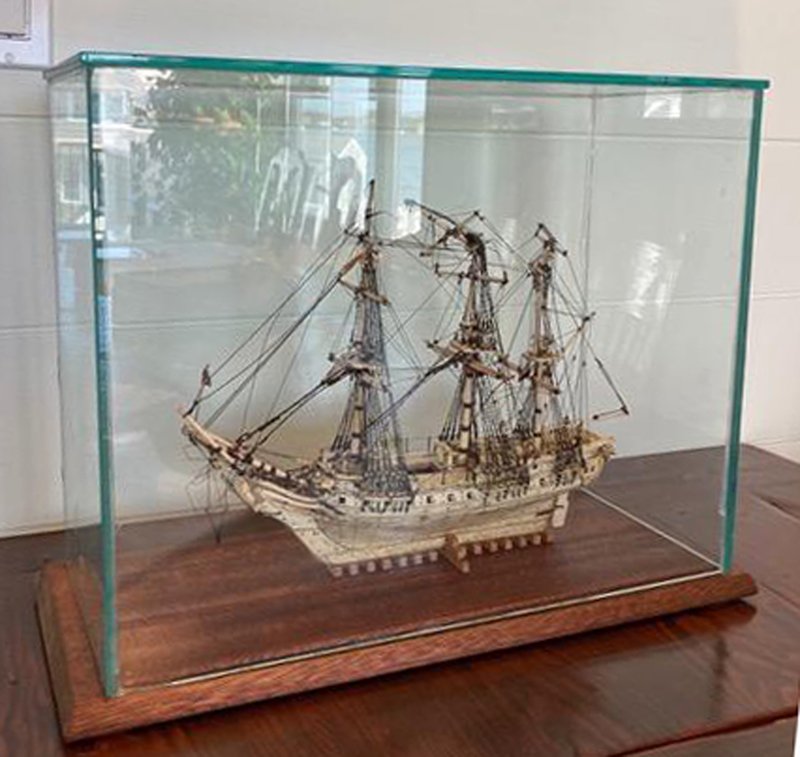
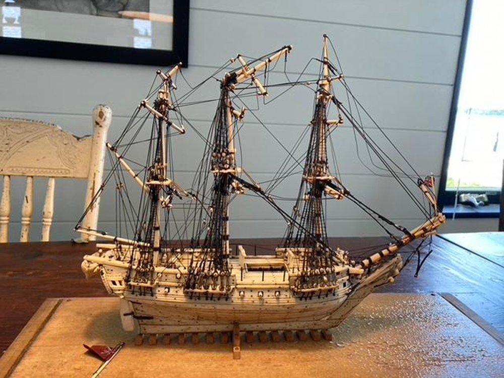
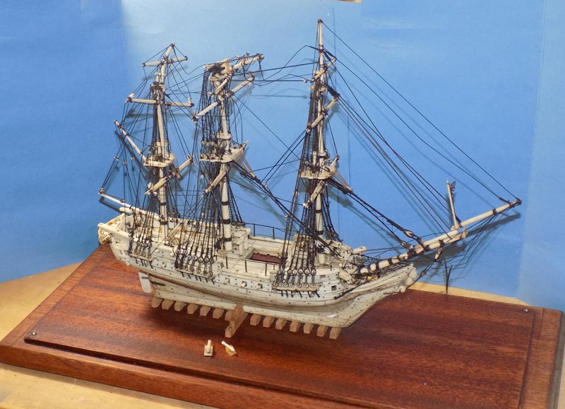
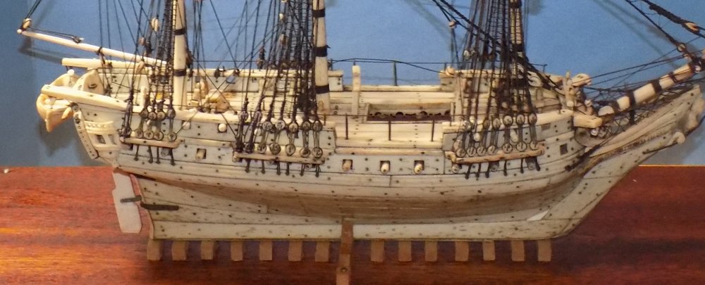
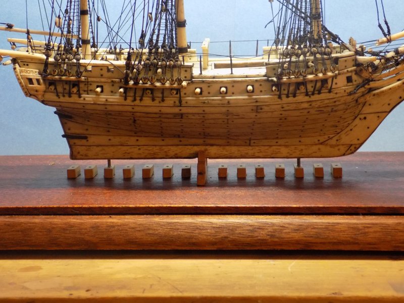
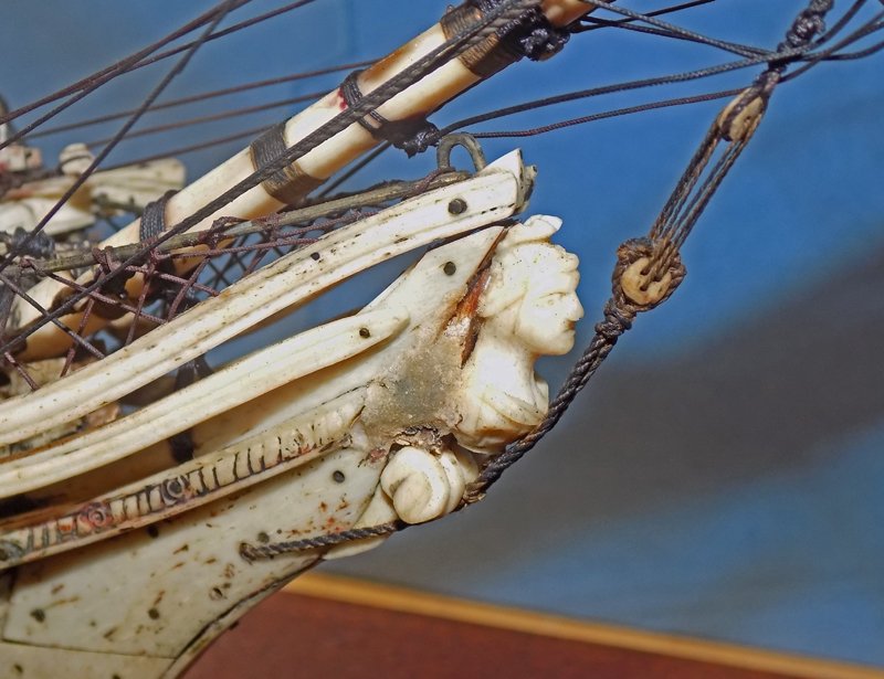
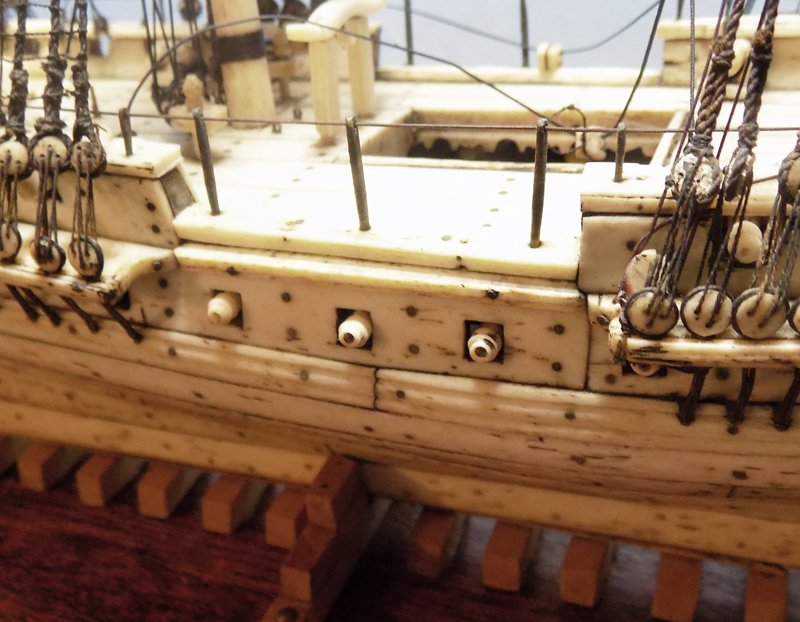
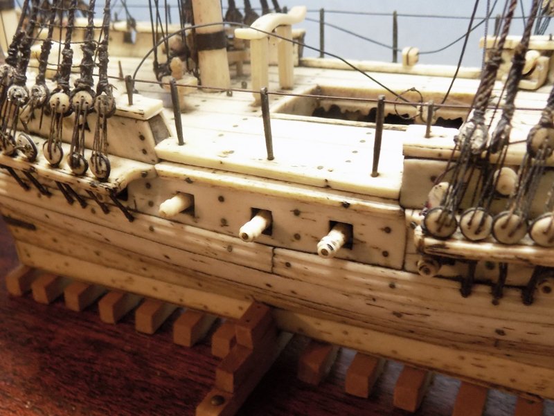
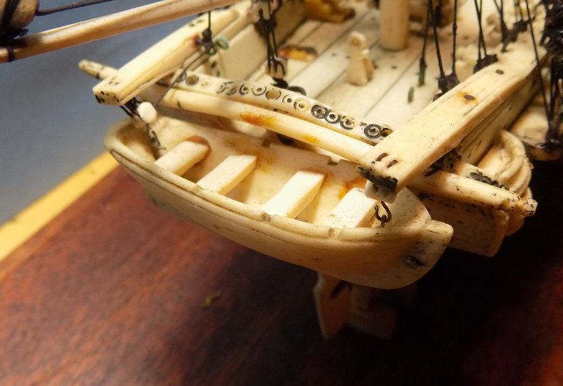
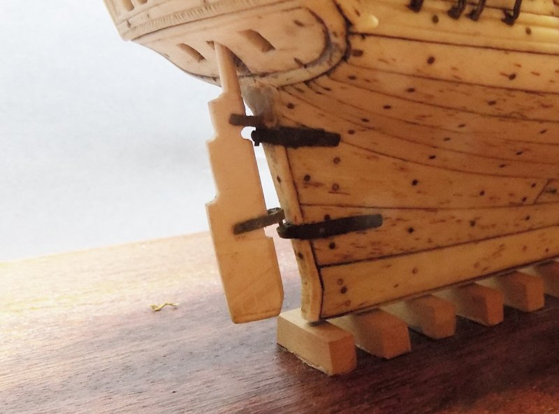
Hello to all who followed me here from my prior build log of the James B Colgate, and to all those who are interested in the bone and ivory ship models made, mostly, by the French prisoners taken by the British navy in the Napoleonic wars. I was recently asked to repair an attractive example of the type that had some substantial damage over the past centuries, as well as suffering some repairs, good and bad. In this log I will detail my progress and, in addition to some techniques that I have used before, I will ask for additional ideas from the collective wisdom of our community here. So here she is in the photographs sent for me to consider doing the restoration. I asked for digital shots of the entire model and close-ups of the damage. First, the overall look, including the wooden base, the primary damages, and the large glass case. With the case removed you can see the extensive damage. The bowsprit, mainmast and mizzen are all clearly broken and the associated rigging in disarray. The balance of the standing rigging seems to be mostly intact except for the mizzen stay which is broken just below the crowsfoot. Sitting on the base are the flag and staff for the stern. In close-up here is the bowsprit, with the jib boom broken at the level of the bowsprit cap and the Y-shaped martingale hanging, literally, by a thread. I don’t recall seeing that type of martingale on any of the POW models whose photos I have seen. Even at this stage I thought it was probably a later replacement. The mainmast was snapped just below the crosstrees at the base of the t’gallant mast. From the way the rigging lines retained the kinks and bends I was pretty sure that they had been hardened in some way. This could indicate that much of it might have to be removed and replaced. The mizzen was similarly snapped below the t’gallant top. In addition the mizzen t’gallant mast was snapped as well about halfway up its length, just where the hole was drilled for the t’gallant lift. Here the rigging was also kinked, but more worrying was the mass of overlapped rigging lines around the doubling. I have seen this before when prior restorers have simply looped new lines over old ones and glued the mass together. Based on these pictures I gave the client a very vague ballpark idea of the cost of repair to see if he was serious about going forward. I told him that if he was, I would need to see the model in person and evaluate it in detail before giving him a firm price. After a few months of thinking about it he brought the model to my Brooklyn studio and left it with me for examination. In this posting I examine the hull and its fittings. The model was uncased and the glass cover removed. It was made of ¼” thick fish tank glass and I was surprised at how heavy it was. By my bathroom scale it weighs some 19 pounds! This probably contributed to the damage. Anyone lifting the cover will have a hard time unless he is prepared for the sudden weight. Trying to lift it clear would be difficult and the lower edge might well have contacted and broken the tops of the masts. In any event, the model matched the photos, which is not always the case. With the jib boom in approximate place the model measures 15 ½” x 12” x 4”. By measuring the spacing between ratlines (3mm) and the height of the bulwarks (11mm) and the height of the rope rail amidships (15mm), I determined that the approximate scale is between 1/80 and 1/100. I could not be more certain because none of these has a standard height and the modelmakers were not quite exact in rendering them. Two of the cannon and their carriages were loose, and a third was found detached on deck. The hull and deck are planked in bone with ivory (elephant or whale tooth is unclear) making up the balance of the structure and carved details. She carries 40 guns, 12 in each broadside on the gun deck, 5 on the quarterdeck, 3 on the forecastle. This is a lot for what appears to be a small ship. She is certainly not a match to any of the 40-gun ships in my library. She sits on a series of wood keel blocks with a larger built up central cradle. Three metal pins, two seen here and one in the center, go through the blocks and into the baseboard. When received the model did not sit vertically, but listed a bit to starboard. Ahe bow there was a nicely carved figurehead of a female bust with a Greek-style helmet and a pugnacious expression . It looked to me to be in the wrong place, slid down below the hair rail. Behind it was a mass of greyish putty hiding some additional damage. There was a similar mass on the port side Despite its small size the lower gun deck cannon are made to retract. Here they are retracted, then extended. The retraction mechanism can be seen through the open main hatch. The cannon barrels are mounted on a moveable wood strip. The client also sent a video taken of the interior through a borescope. It is poor quality but it does show the presence of some springs which would push the cannon out. Unfortunately the cords to operate the system are missing. On deck just ahead of the mizzen mast is a carved seat for the officer of the deck. This is a particularly French detail, even though the model carries English flags. The locations for the detached cannon can be seen against the far bulwark where the prior glue has yellowed. Hidden behind the rigging is a metal post where the capstan should be, and a single stand for the ship’s wheel, although the wheel and second stand are missing. A ship’s boat hangs in davits at the stern. The thwarts for the boat have been repaired before with a glue/varnish that has yellowed with time. Just ahead of it is a curved boomkin for the main yard brace, but no lines are tied to it. The rudder is clearly a replacement. It is too thin and too white, while the pintles and their straps are not properly set on the rudder. That was my detailed examination of the hull. In the next segment I will document the detailed examination of the masts and rigging. Lots of problems, as you might expect. Be well, stay safe. Dan
- 95 replies
-
- 28
-
-
- POW
- Bone model
- (and 2 more)
-
Hi Marc - Looks great. Wish I could see her in person, but I guess I will have to wait a bit more. I was going to suggest that you work on the transom and counter by turning the piece upside down so it faces you, but I see from the last two photos that you figured that out. Are you thinking of muting the colors in any way to mimic the atmospheric effects of distance and haze? Dan
- 2,699 replies
-
- 3
-
-
- heller
- soleil royal
- (and 9 more)
-
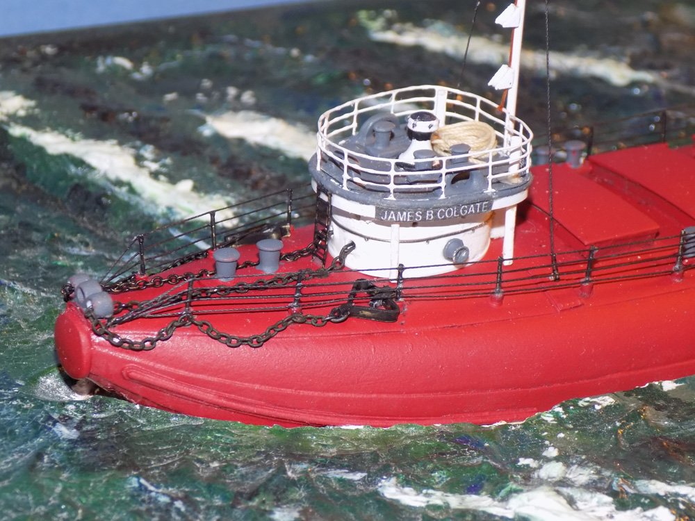
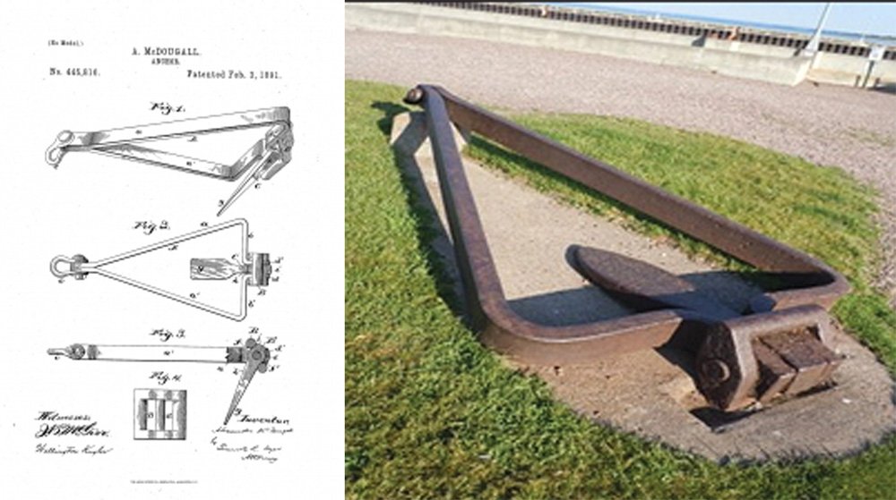
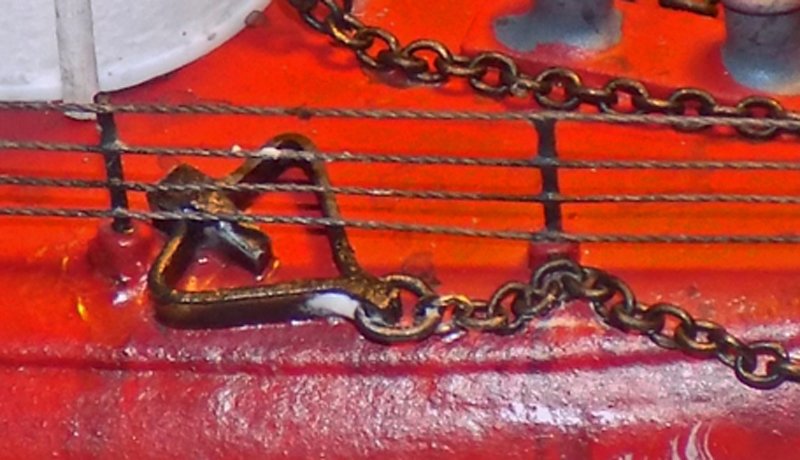
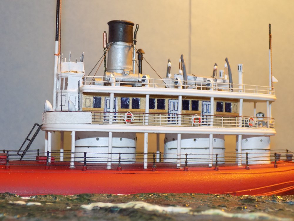
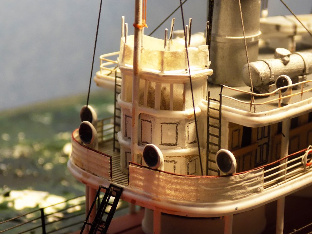
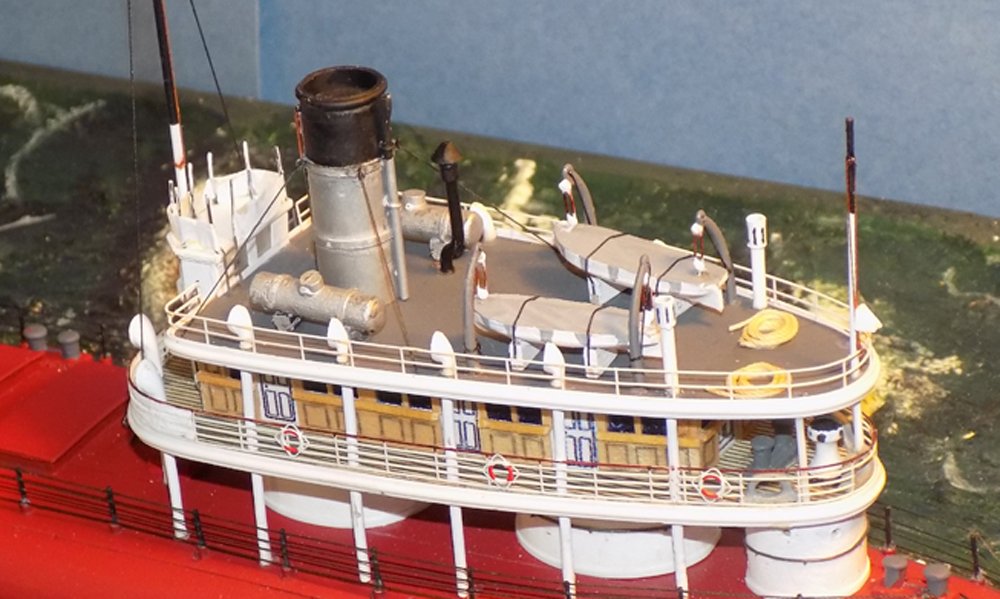
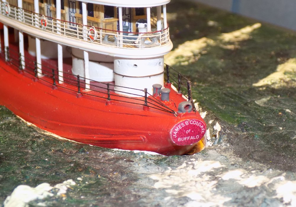
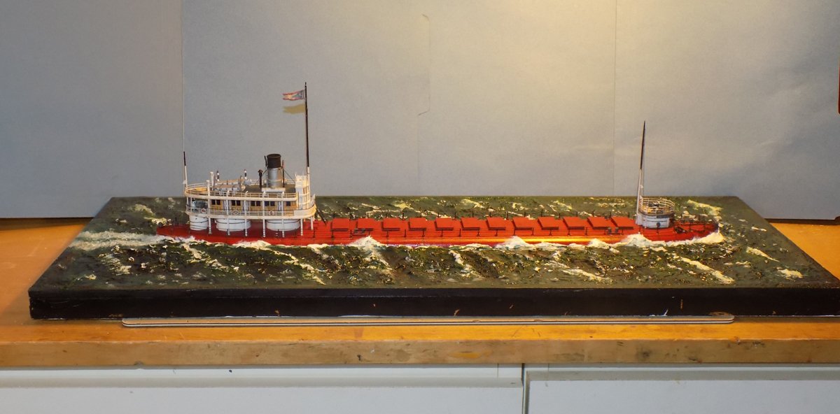
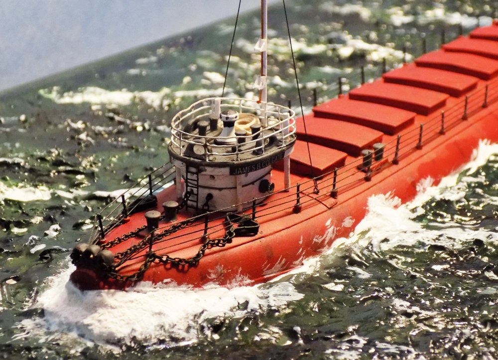
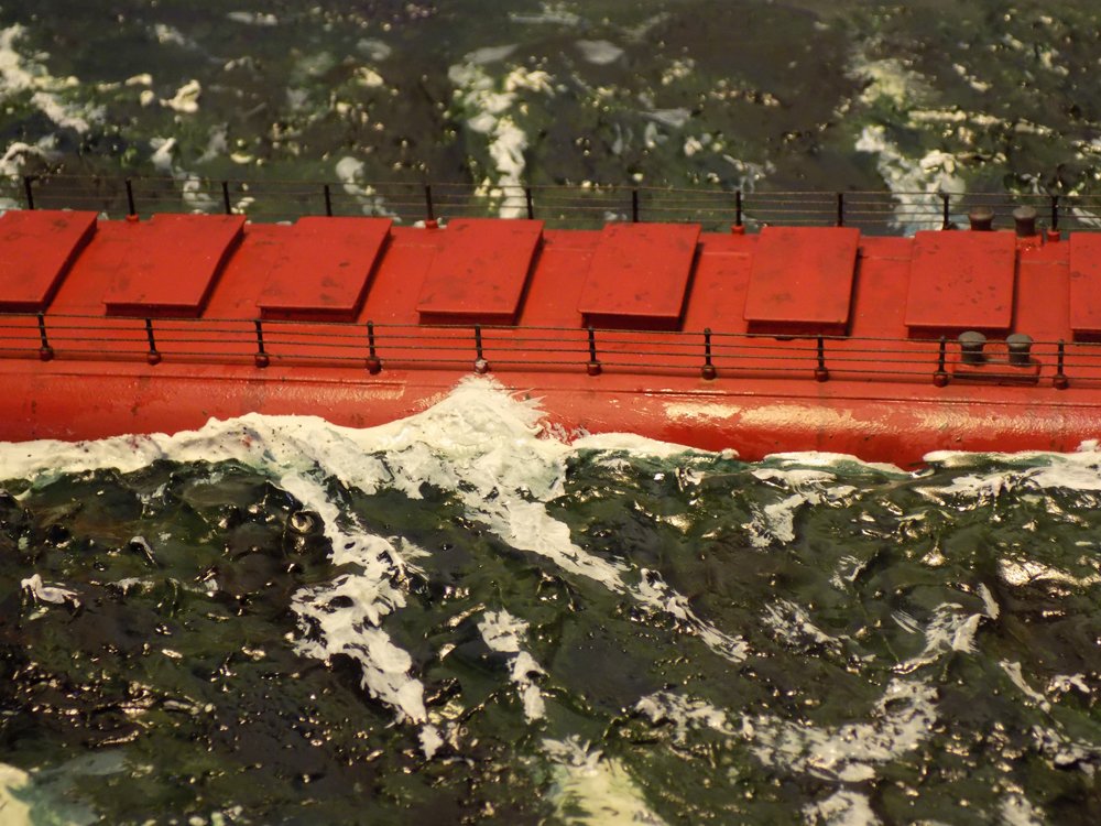
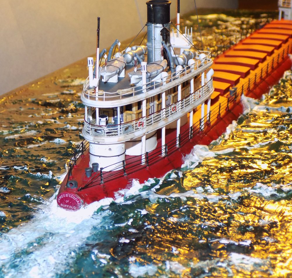
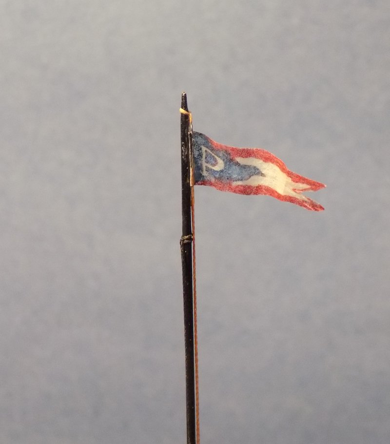
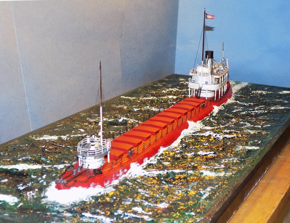
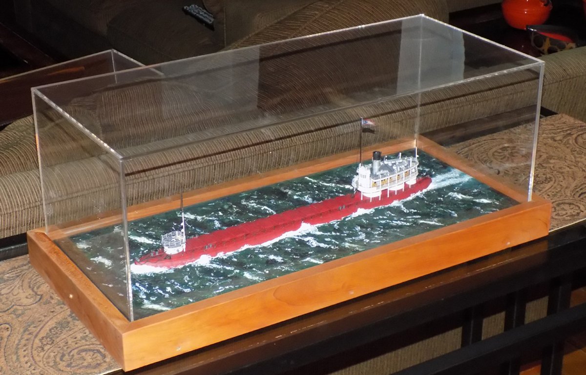
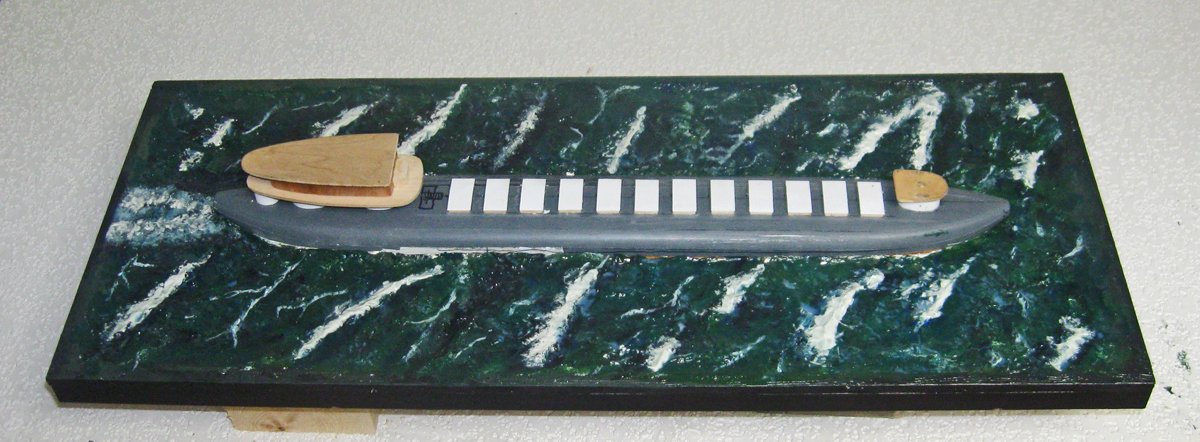
Hi again to all my friends here and, as always, mucho thanks for the likes and comments. Yes, Keith, this will be a quick build log for several reasons. Mostly this is because it is a retrospective of the construction rather than a day by day series of small progress reports. I have detailed many of my techniques in earlier build logs, so there was little need to go over them again. At least that was what I told myself as Covid malaise set in and I found myself not willing to stop to memorialize small personal gains amid larger world problems. It just seemed a bit trivial. Thankfully I certainly did not suffer any of the serious health issues or losses that so many have, like Doris in Czechoslovakia. Fortunately, I have climbed out of my depressive hole, and am working steadily again. I have to credit my family and friends with most of the recovery, but model building made a significant contribution as well. There is just something satisfying about looking at a well-crafted object at the end of the day and knowing that it only exists because of my hands, my head and my heart. Long may it be so. So, without further maudlin ramblings, here is the completion and launching of the SS James B. Colgate in its plaster sea. When the last installment ended the sea was mostly finished, although I looked at it every day and kept toning down the size and location of the whitecaps which I thought were still too bold and glaring. Meanwhile I turned to finishing the ship. After the hull was shaped the hatches were permanently installed. Along the sides of the hull several reinforcing stringers were added according to the plans and photos. These were made of half-round strip set over flat strips with rounded ends. Fittings that would ultimately be painted, such as bollards and the bases for the railing stanchions, were attached to the hull. Then the deck houses were removed and the hull was sprayed the deep red used by the Pittsburgh Steamship Company at the time. Some, like bollard uprights and the anchor guides, were subsequently painted grey for contrast. Then the deck houses, like this one at the bow, were built up and detailed before being secured to the hull Most of the details are pretty simple and common. Bollards, fairleads, winch heads and the capstan are Bluejacket castings. The railing and ladder are photoetched brass from Gold Medal Models. The nameboard is printed on my computer. I’ll go over some of the others where they appear in later photos. The one unusual fitting is the anchor. McDougall, the designer of the whalebacks, also designed it as a better alternative for use on the boats. It consisted of a heavy triangular frame with a shackle at the peak and a pivoting tongue in the middle of the base that would dig into the seabed of the Lakes. As can be seen on the model it lies much flatter on the hull than a conventional anchor and could be easily secured to the stanchion bases. I made it out of two strips of thick brass bent to shape and soldered at the peak and at the base where a separate brass tongue was fitted. I did not make any effort to have it pivot since this is a static model. After blackening it was fitted with a ring and fine chain. At the stern the deck house is much more complex. The lower level has the two larger oval support structures with a smaller round support at the stern. The forward two were made by sheathing oval wood plugs with styrene sheet. Portholes were drilled and filled with small brass grommets from dollhouse electronics systems. After painting handrails of iron wire were laid on with tiny supports inserted just underneath and clipped off close. The upper works began as a solid wood block, as usual, but this was sheathed in wood veneer rather than plastic. The window and door areas were left uncovered with the windows simply painted black and the doorways filled with printed 4-panel door appliques. Upper railings and life rings are photoetched brass. The angled stairway is a photoetched ladder with added side pieces cut from railing sections, secured with cyano and painted black. At the forward end of the upper deck is the bridge which rises another half deck height. It was built hollow with clear plastic windows on the front and back faces of the top. Through these you can see the ship’s wheel that was installed and which no one, except in these photographs, will ever see. The cowl ventilators are modified castings that sit on the top of cylinders that act as both structural supports for the decks and as ventilation ducts leading to the interior of the hull. I took a bit of artistic license and simply drew on the paneling in pencil, relying on trompe l’oeil and the tiny scale to fool the eye. The roof of the deck house is dominated by the large silver and black funnel. It is built up over a plastic sheathed dowel, leaving a 1/8” rim at the top. Reinforcing rings and a half-round lip at the top are made from plastic strip. All of the plastic products are from Evergreen Scale Models, an invaluable resource when building steel hull modern ships. The funnel is detailed with a steam whistle and pipe on the front face, and a steam release pipe on the aft face. It is guyed by four wires running from small eyebolts on the upper reinforcing ring to brass tube turnbuckles on deck. The Charley Noble galley stack has a cone shaped rain guard and a kink near the deck. This last is either to get the stack around the funnel guy wire or as a trap for condensation, of maybe both. It appears in the photos so it appears on the model. A pair of liquid tanks, one for water one for fuel perhaps, bracket the funnel. A pair of lifeboats with their davits and lifting tackles are tied down on cradles. Eight small cast cowl vents and a pair of cylindrical exhausts run along the edges of the busy space. At the aft end is a vertical pole, not for a flag, but for a lantern which would be fitted into the triangular shelf shown near the railing which could be hoisted to the top of the pole when visibility was limited. At the stern the rear name plate was printed to match the one seen in contemporary photographs. It shows up as a slightly different shade in this photo, but that is an artifact of the flash, and under normal light it is much less noticeable. The railing on the hull could not be photoetched since the lines had to come to a point at the bow and stern. I made the stanchion bases from 1/16” plastic rod and the uprights from 0.02” brass rod. These dimensions are about twice what they should be, but when I made them to scale they almost disappeared, so I fudged the figures a bit. The horizontal wires are 0.05” polished line. Again, slightly too large, but they match the photoetched railings and do not draw the eye when the model is viewed without magnification. The lines are tied under light tension to small eyebolts at bow and stern, then attached to the uprights with thin PVA glue painted on with a small brush. Until now the ship has been simply placed in the opening left for it in the plaster sea. Now it was secured with a pair of screws through the base plate and plaster carefully fed into the gap between it and the sea and shaped to a dynamic wake. At the bow the wave was built up in several layers to match the wide froth thrown up by the blunt pignose bow. The final layer is stippled with a stiff coarse brush. Little wisps of white paint were dry brushed along the hull in the direction of travel. This was all blended into the sea with more layers of tinted gloss medium. Along the flanks of the ship wave crests rose up the side to the level of the railing and left subdued whitecaps on and under the water. Here you can also see the minimal weathering applied to the model. A thin wash of dark brown left spots and streaks on the hatch covers. A similar wash discolors streaks that drip from the railing bases. Wet patches of clear gloss finish glint on the hull. At the stern the wake from the two propellers moving slowly was stippled onto and into the surface of the sea. The sunlight reflects yellow on the water. Looking carefully you can see where I have, at random locations, bent the metal railings to show a bit of hard usage over time. The final detail was the burgee of the Pittsburgh Steamship Company. An image was located on line, dropped into PhotoShop, sized to the model and had the color saturation slightly reduced to mimic the effects of distance and haze. The image was skewed down a bit to take into account the way gravity affects wind-driven cloth. The image was printed onto acid-free tissue paper which had been sealed with clear finish before printing. This prevents bleeding into the paper fibers and gives a clean edge to the colored areas. After fixing the colors with more clear finish the flag was cut free, attached to a halyard and tied to the flagpole. A few curls with the back of a small paintbrush handle and it was done. The model is now complete and chugs realistically, I think, though a choppy but fairly calm sea. As part of the commission I built a display case from 2” x ¾” cherry, mitered at the corners and fitted around a ¾” plywood baseplate. A UV-resistant plastic case was sourced from a local plastic shop. It fits into a slot between the case and the base and is secured from accidental lifting with two small brass screws on the short ends. A bit of air movement is provided by small holes drilled up through the bottom of the baseplate and into the gap under the plastic case. The model now resides in the MMA museum in the Great Lakes area. Once we are all vaccinated and this pandemic is behind us, I hope you can find the time to visit this small but interesting maritime museum. Next, for something completely different, I will detail a repair and restoration of an antique bone and ivory POW model from the late 1700s that I am working on now. This will be more of a blow-by-blow exposition since the techniques and materials require some inventiveness to match the unusual nature of the model. Until then, Stay safe and well, and get those shots. Dan

- 33 replies
-
- 21
-
-
-
- James B Colgate
- whaleback
- (and 2 more)
-
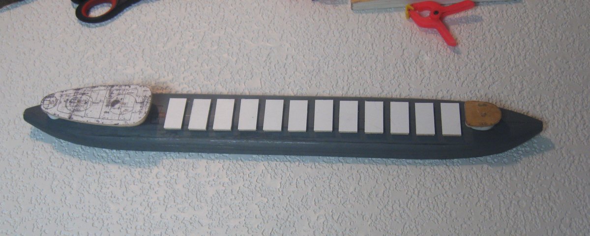
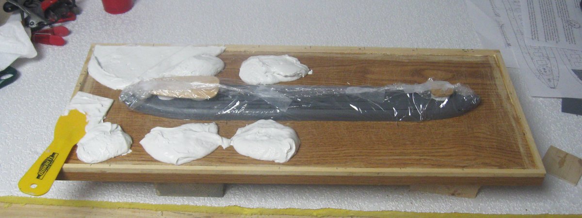
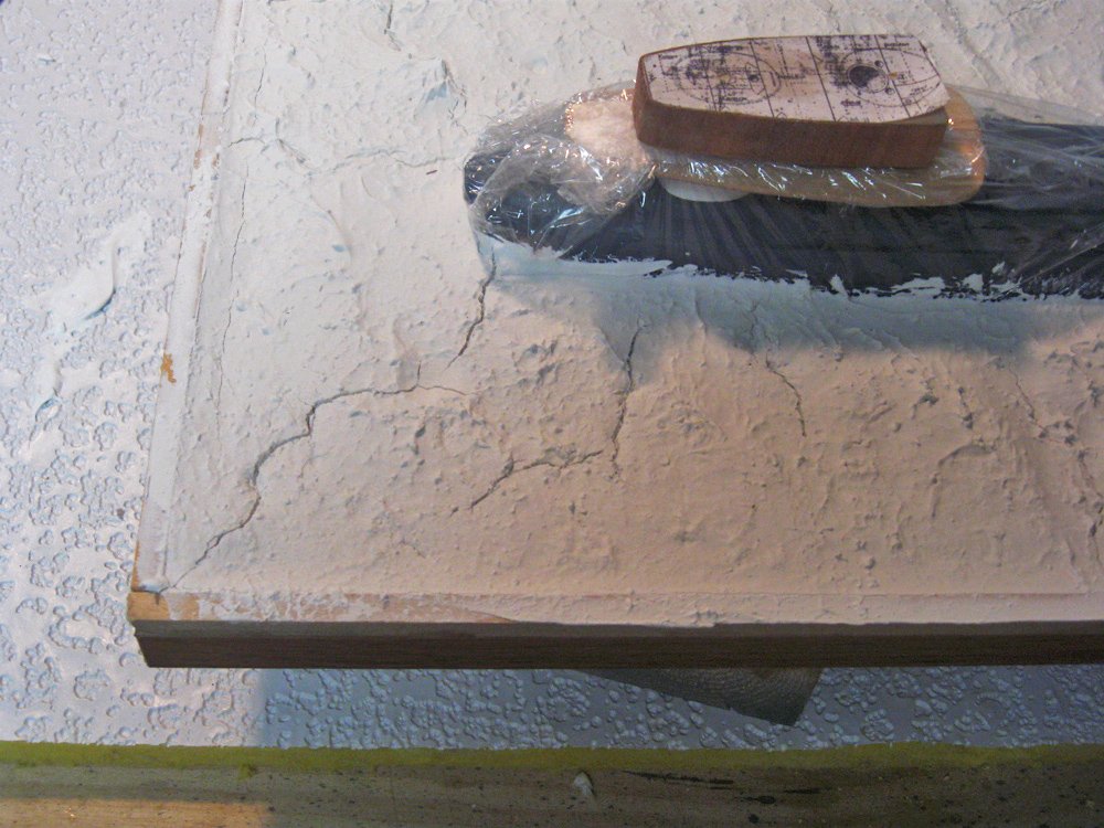
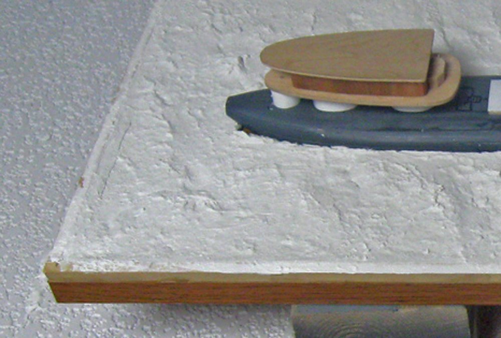
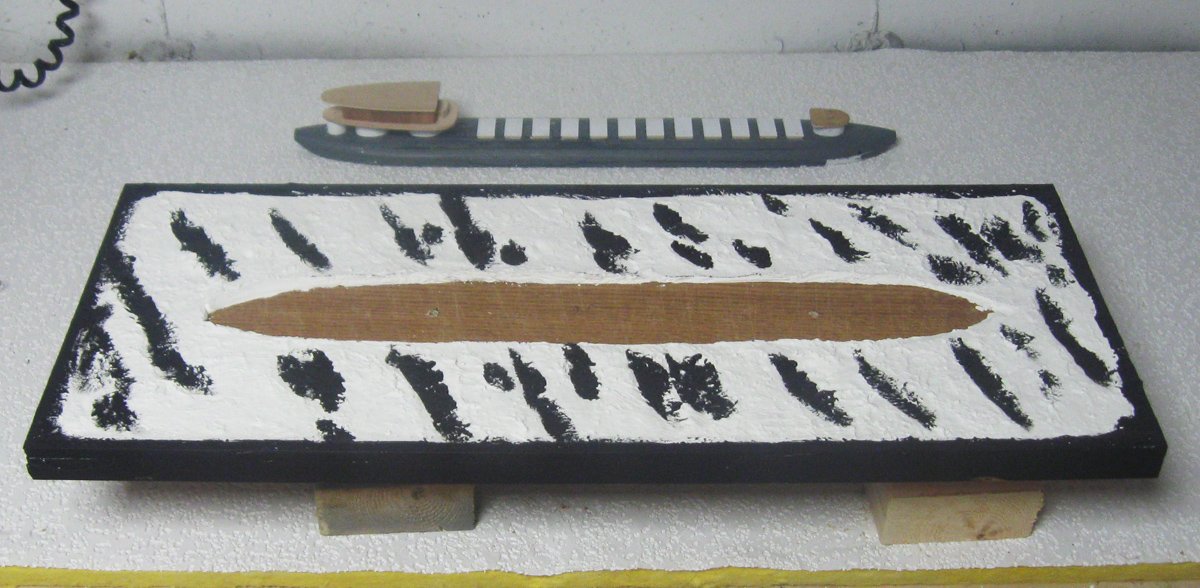
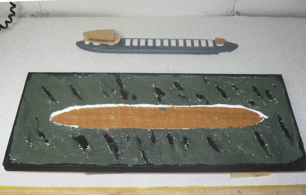
Thanks, as always, for the likes and comments. I hope you are enjoying the write-up. After the hull was shaped and sealed it was plated. The midships plans show only a few wide strakes of 1” steel plates that run the length of the hull. They were marked out and cut from 0.05” black styrene sheet, then applied to the hull and secured with contact cement. At the bow they were tapered and curved to meet the round bow plate. This was done in a similar fashion at the stern. After plating the hull was given several coats of grey primer, sanding between coats. At the bow the deck house was built from the section of PVA pipe ground oval to match the plans. The roof of the deck house was cut from a piece of 1/8” hardwood. The rear corners are sharper than shown on the plans, but match photos of the Colgate. At the stern the three supporting structures were made up from solid wood sheathed in plastic and secured with cyano. The forward two are oval, while the aft one is round. The upper deck of the aft house was also cut from 1/8” hardwood sheet, following the plans which were tacked in place to guide the cut. It is only placed on the supports for now until they can be detailed. The twelve hatches were built up from wood pieces bent to a curve to match the hull, then topped with styrene sheet. The contract calls for the model to be displayed on a molded seascape, as with all of the models in this commission. The process was similar to that done for the Leviathan. This was actually done before that of the Leviathan, so I was experimenting a bit as I went on. I did it early in the building process so if it failed I could scrap it without too much time lost. It started with a baseboard cut from a commercial ¾” MDF shelf which was the desired 12” width, but too long. It was cut to length, then the cut end was sealed to prevent moisture entry that might have warped the base. The hull was wrapped in kitchen plastic and secured to the base with two screws from the underside. A ¼” lip was secured all around the perimeter and dollops of prepared spackle were plopped onto the base. The first layer of spackle was spread in an even layer up to the hull. It was roughly shaped with a spatula to form parallel grooves at a slight angle to the hull. Since she was lost in a storm I wanted to show a choppy sea, so the grooves were fairly deep. This first layer shrank as it dried, giving me room for the second layer, which was good, but the plaster cracked, which was not. After the first layer had dried for several days the top layer was laid on. I thinned it a bit and laid it on with a stiff paintbrush. This filled and hid the cracks in the first layer. While the plaster was still wet I dabbed it all over with a damp coarse sponge. The sponge lifted up the plaster into many small peaks, imitating the surface of a vibrant sea. Where the plaster was still too wet it slumped down, and those areas were dabbed again until it held the little peaks. After another two days of drying I started coloring the sea. Artist’s acrylic paints were used throughout. The deepest hollows were painted flat black, as were the edges of the base. The black was followed by dark green overall, with some sea blue applied to random areas. I did not worry about complete coverage since the small spots that did not take the paint would show up as random variations, just like the real sea. Painting continued with multiple coats of clear gloss finish tinted with blue or green which built up a convincing feeling of depth. Flat white was dabbed onto the crests of the wave forms and pulled aft as would happen with the direction of the wind. Similarly, the wake was stippled onto the sea aft of the hull. At this stage the model was removed to finish construction. Once completed, additional plaster will be formed to the hull and even more layers of transparent glaze will be applied to tone down the waves even a bit more. Final construction and presentation next time. Until then, stay safe and well. Dan
- 33 replies
-
- 17
-
-
- James B Colgate
- whaleback
- (and 2 more)
-
Nice and clean, Marc. I like the color combinations. Dan
- 2,699 replies
-
- 4
-
-
- heller
- soleil royal
- (and 9 more)
-
Hi Keith - Like you, I use thin CA on small hardwood parts, especially open end grain, to stabilize the wood. However, on larger parts and softwoods I use a product from Minwax called "Wood Hardener" which does the same thing and is orders of magnitude less expensive than CA in the small bottles. Available from Amazon for $13 a pint. Probably less from some other sources. As always, I am left speechless at your precision metalwork. Dan
-
Really beautiful, Keith - I can easily imagine walking her deck in a fresh breeze with a cold cocktail in my hand. Is she available for a charter to the Bahamas when this wretched covid thing is behind us? Dan
-
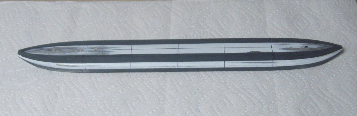
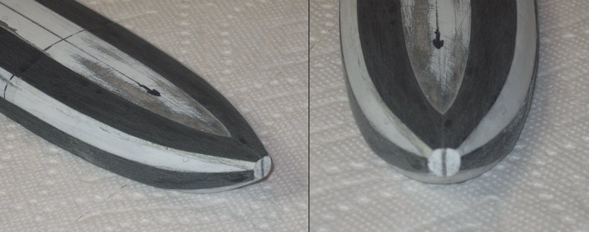
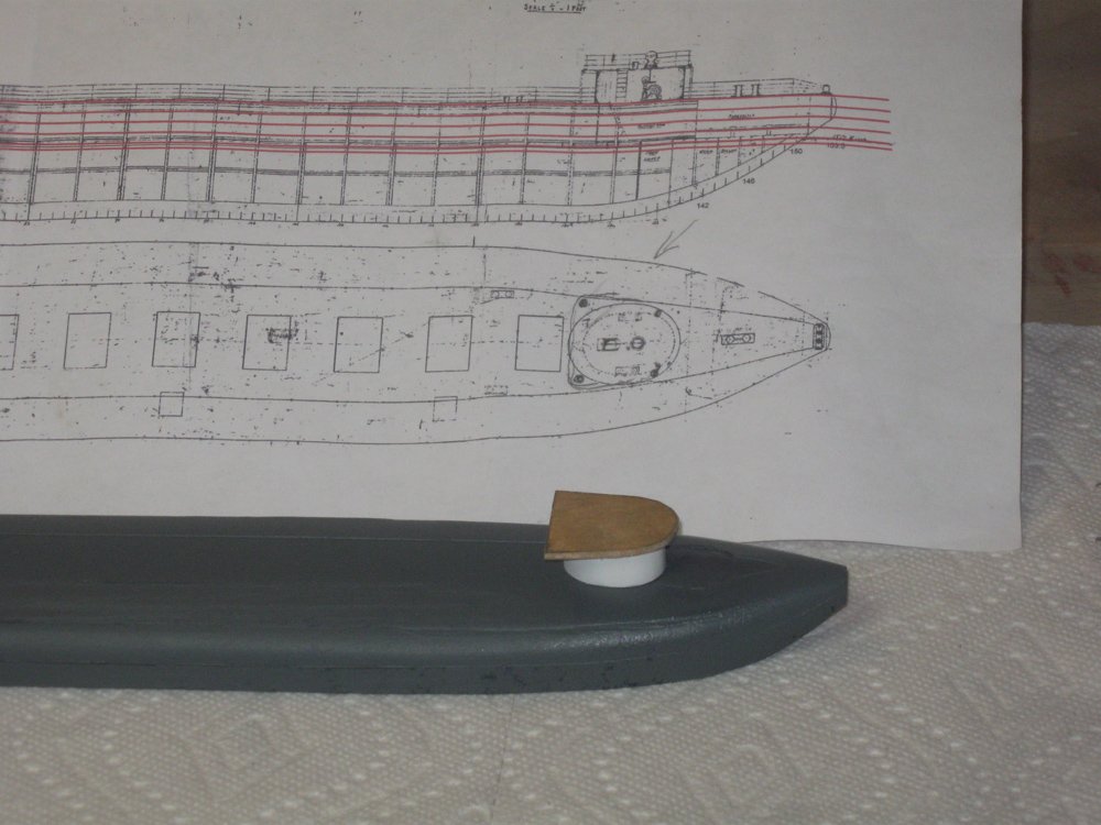
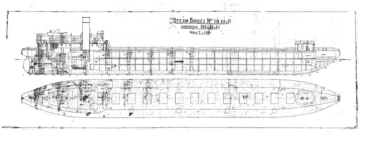
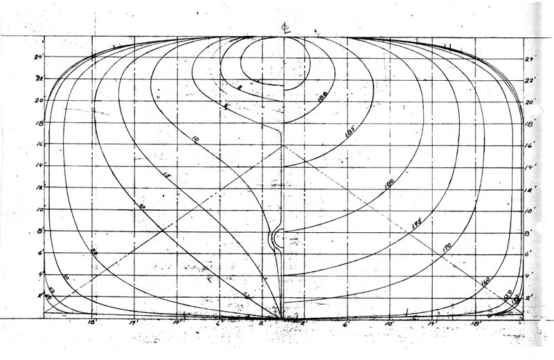
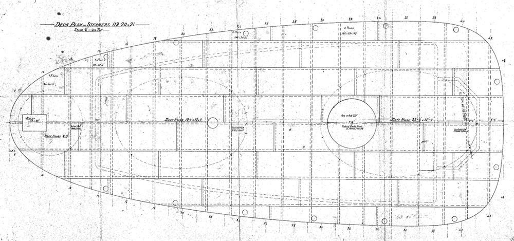
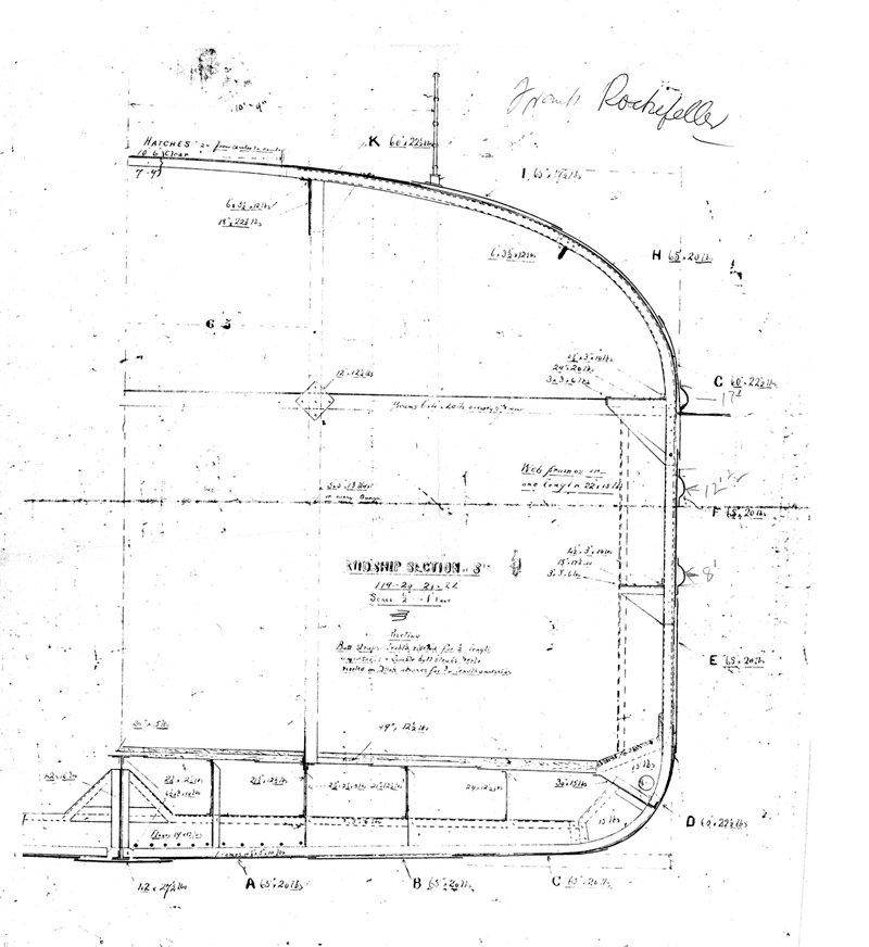
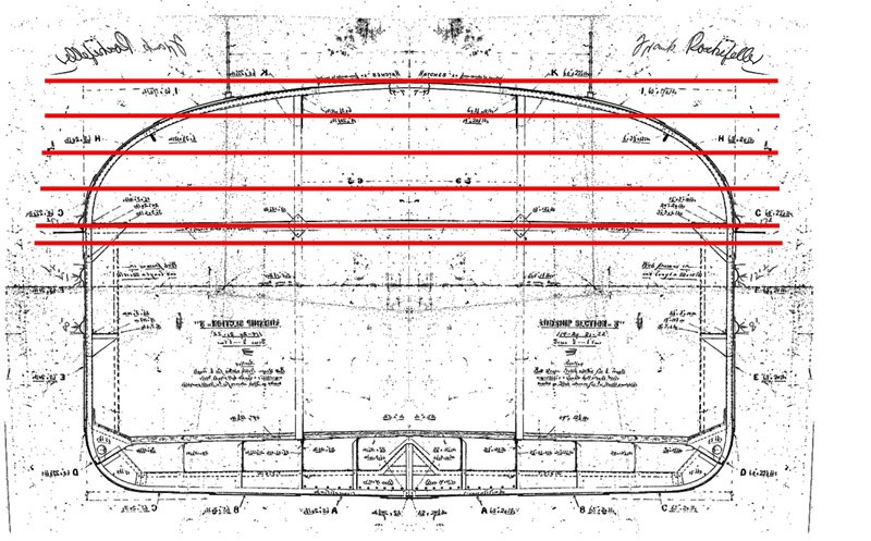
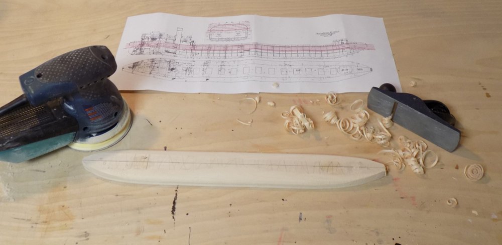
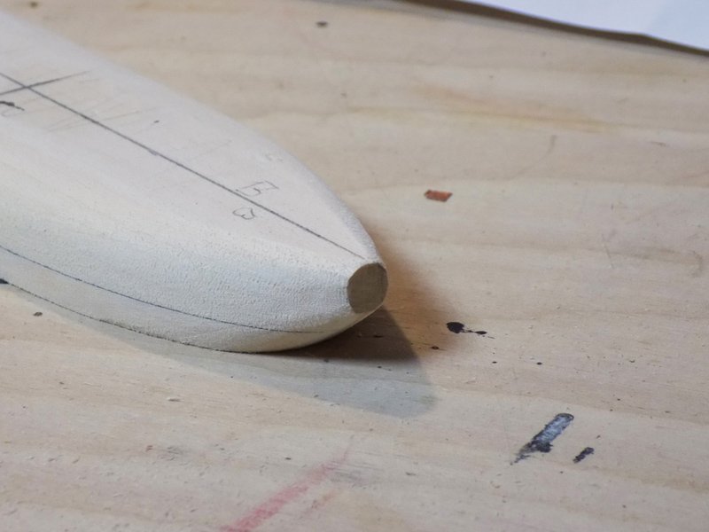
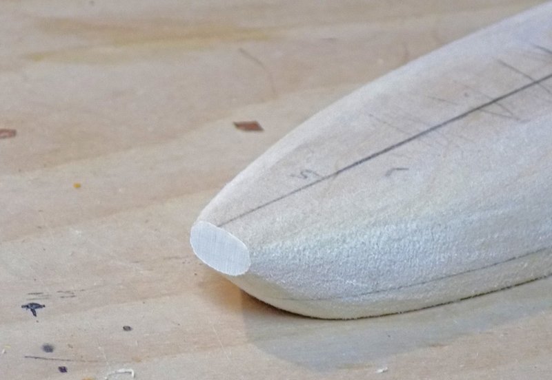
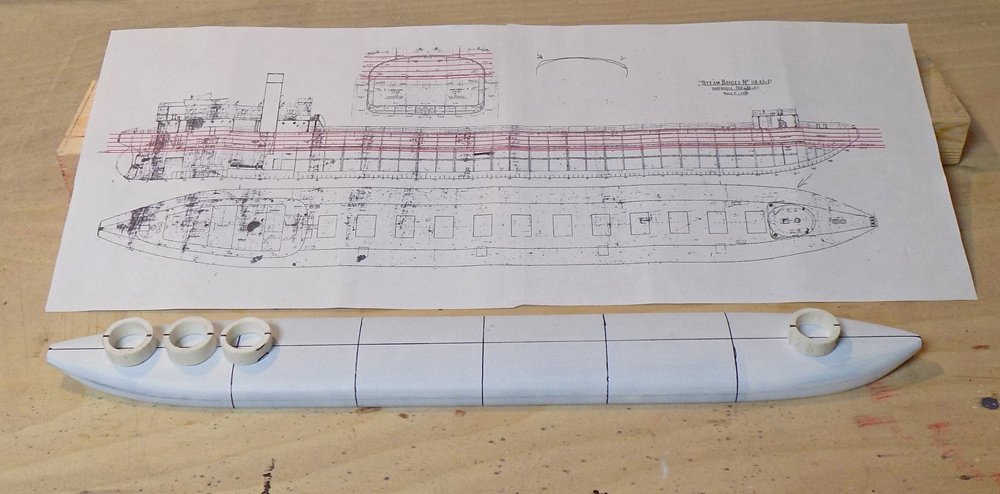
Hi to all - And thanks for stopping by and for all the likes and comments. Roger and Lou - yet another nice bit of maritime history about the Everett. She would make an interesting subject to build (if someone will pay me to do it - - LOL) Research and construction began, as for all of my models, with an exhaustive search of the available images on the Internet. In addition, two books were of particular assistance: “McDougall’s Great Lakes Whalebacks” by Neel R. Zoss and “Whaleback Ships and the American Steel Barge Company” by our fellow MSW member C. Roger Pellett. Thanks go to him for his excellent book and for graciously answering questions when I was stumped. From these I obtained a good idea of the shape and arrangements of whalebacks in general and the Colgate In particular Of course, a decent set of plans is a necessity. After a canvas of the available sources a set was obtained from the National Museum of the Great Lakes for not much money, and I thank their librarian for her help. Although the plans are for steamers 119-121 which are slightly longer than Colgate, the beam and depth are the same. Accordingly, I shortened the plans in Photoshop to the correct length and cleaned up the foxing that obscured some of the details. The lines plan of the whaleboats clearly shows how unique the design was. To my mind it almost looks as though the hull of a “normal” ship had been turned upside down. What do you think? From another source I located a plan of the stern deck house that laid out the two oval and one round supporting structures along with some of the details of the bridge, cabins, and stern bollard and winch. The midships engineering drawing from the museum was of great help in locating hatches, railings, and longitudinal half-round stiffeners along the side of the hull. It also indicated that the hull was plated in wide, in and out strakes. This was confirmed by several of the photos of various whalebacks. Using this midships plan, I cut it along the centerline, mirrored it, then overlaid red lines for possible lifts. Since the model was requested to be a waterline display, only 9 feet of freeboard would be needed. This meant that the hull blank would be 9/16” high/thick. I added an additional 1/16” so the final blank was a half inch lift over a 1/8” lift. These were glued together with black PVA glue that indelibly indicated the waterline location. The wood was then shaped with a plane and power sander to close final shape and dimensions. The bow tapered to a round flat stump – the pigboat look. The stern tapered to an oval stump where the name and home port legend will appear, as seen in the first photo in this segment. After close shaping the hull was given several coats of primer before final sanding and shaping. After a coat of white primer the hull was marked with a centerline and several station line locations to match the plans. Four slices of 1” plumbing pipe were temporarily placed on top to visualize the bow deck house and the supports for the stern house. Construction continues with hull plating in the next segment. Until then, stay safe and well. Dan
- 33 replies
-
- 17
-
-
- James B Colgate
- whaleback
- (and 2 more)
-
Really great work, Gary. I followed along from the beginning and learned many excellent techniques along the way. Looking forward to your next project. I have my popcorn all ready. Thanks again for sharing. Dan
-
Hi to all who followed this build log. I hope you enjoyed the journey, and I thank you for all the likes and comments. I have just posted the first piece of a new log of building the Great Lakes whaleback steamer SS James B. Colgate (1892) If you want to follow along just click on the ship's name in the 'current build' line of my signature below. Everyone is welcome. Stay safe and well, and a Happy Thanksgiving to all. Dan
- 238 replies
-
- 7
-
-
- leviathan
- troop ship
- (and 2 more)
-
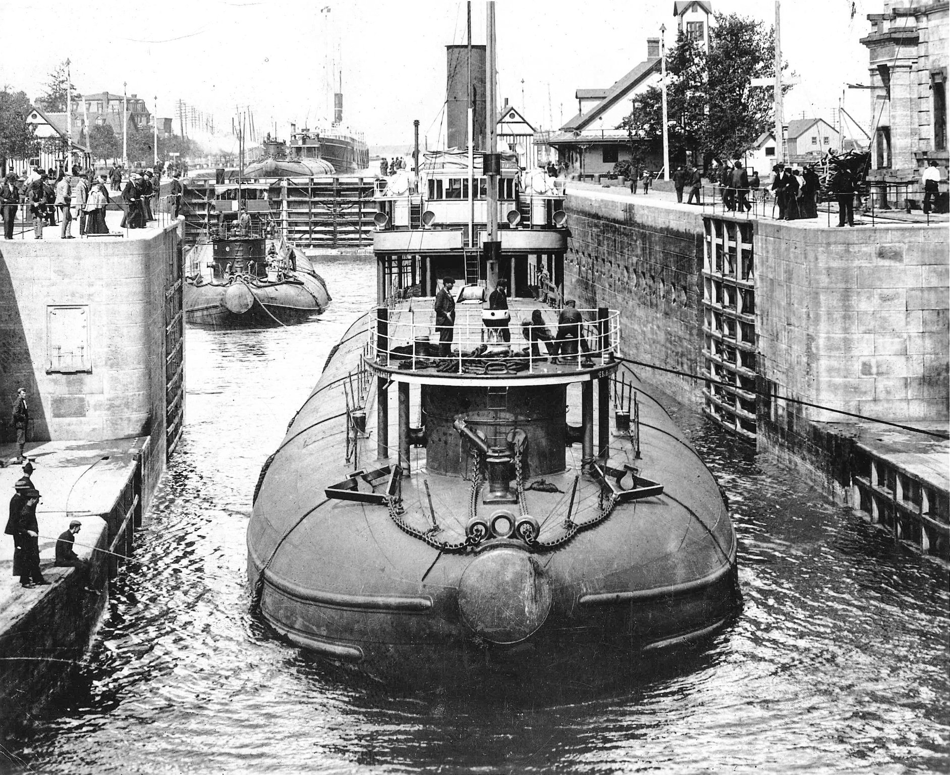
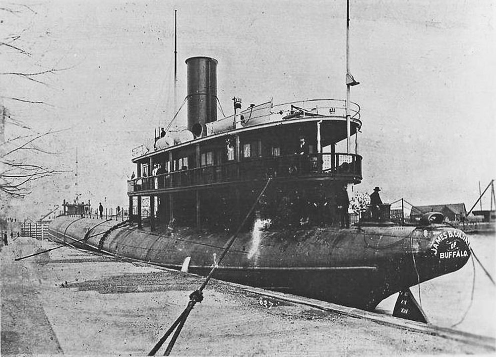
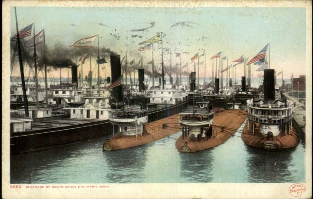
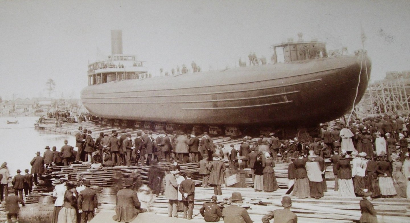
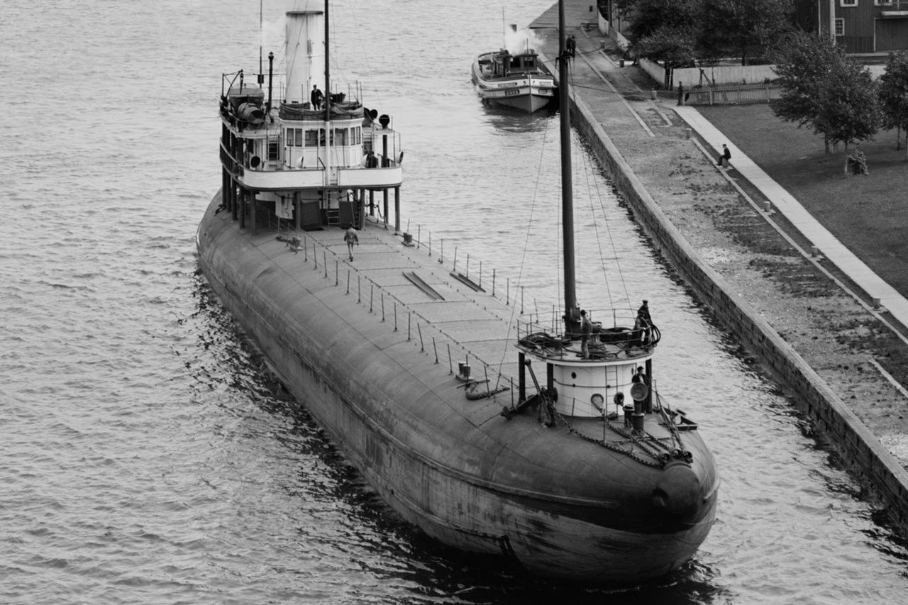
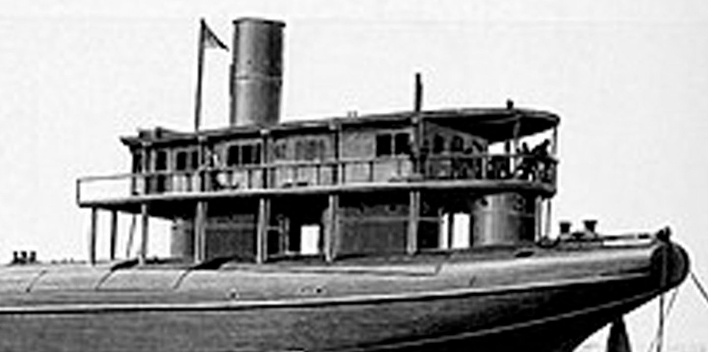
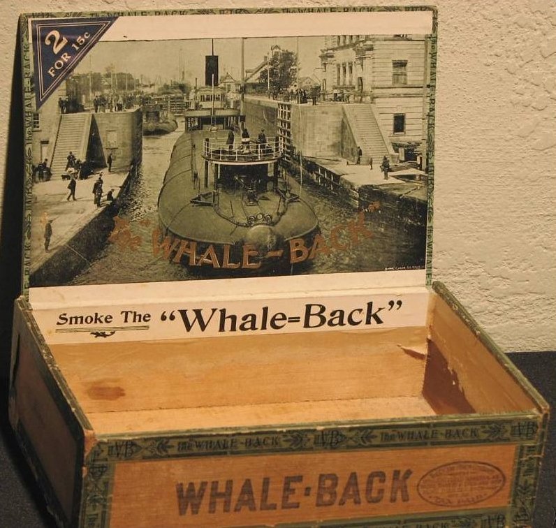
Hello to all in this strange time – And thank you if you have followed me here from my last build log of the USS/SS Leviathan I apologize for the long delay between the end of the Leviathan build log and this, and also that It will also not be as detailed as my last write-ups. I will point out some building techniques that are a bit different from former ones, but for the most part it is more of a tour of the completed model than a blow-by-blow description of the construction. This is the second of seven models for the US Merchant Marine Academy museum. The subject is the whaleback steamer James B. Colgate, built in 1892. Designed by Capt. Alexander McDougall, these boats were a major departure from accepted ship design. Rather than sitting high on the water these boats rode, when loaded, with little of the ship above the waves. The idea was that, like a floating log, it would let rough seas pass over it rather fighting them. As an aside, the postcard above, titled “Blockade of Boats at Sault Ste. Marie,” commemorates a significant moment in the history of shipping on the Great Lakes. On September 5, 1899 the 500 foot long bulk cargo steamer SS Douglass Houghton was towing a barge named the John Fritz. Both were owned by John D. Rockefeller and together were loaded down with 15,000 tons of ore. The Houghton lost control and came to rest completely across the navigation channel leading to the Soo Locks, the bottleneck between Lake Superior and Lake Huron. Unfortunately the size of the ship made it nearly impossible to free her and the entire volume of shipping traffic through the locks, greater than at any other point in the world at the time, came to a standstill. It was not until five days later that divers and engineers were able to free her by dynamiting the banks of channel. By then more than 200 ships, many of them the largest in the world, were sitting idle. There were so many that when the blockade was finally cleared the line of ships moving single file through the gap was more than 40 miles long. The event triggered hearings in Congress and ultimately led to changes in the administration and maintenance of the inland waterways of the United States. The whaleback design proved surprisingly successful and 43 barges and steamers were built between 1888 and 1898. Although there may have been little of the hull above the waterline, like an iceberg there was a lot more below that the eye could not see. McDougall designed them around the new triple expansion steam engine that used 40 percent less coal, yet could still drive them along at 14 knots, very speedy for bulk carriers at the time. Twelve large hatches opened into a large cargo hold which could be loaded quickly from automatic conveyor belts. The design was finally supplanted in the early 1900s by much larger ships which could weather the large winter storms (the example of the Edmund Fitzgerald notwithstanding). Despite their commercial success, the whalebacks were not popular. The design was too radical, and was resisted by the old guard. They were also not very attractive. The upturned bow with its round stubby front plate may have helped the boats to skim over the water, but earned them the nickname “pigboats.” The Colgate was a typical whaleback steamer, 308 feet LOA with a beam of 38 feet. She carried up to 3,500 tons of cargo in her hold, usually iron ore or coal. A small round deck house at the bow handled the anchor machinery and helped with navigation. On the roof of the deckhouse were several bollards and fairleads for the mooring lines. The midships hatches, as designed, had flush covers that had to be bolted down individually. A later modification had raised coamings which were easier to operate. At the stern was a much larger two-story deckhouse which contained the bridge and some small cabins on the upper deck. These were supported by three round structures similar to the bow deckhouse, designed to allow large waves to flow around and between them with as little resistance as possible. Despite these design innovations the Colgate was lost, with four other ships, in the large ‘Black Friday’ storm on Lake Erie on October 20, 1916. 25 of her crew of 26 were lost, with only the captain surviving. So, after a full 24 year career of productive and profitable service, the Colgate is remembered as an example of radical marine design that was successful for a few decades, and as an icon of Great Lakes memorabilia. Next time, research and construction begin. Thanks for looking in, and stay safe and well. Dan

- 33 replies
-
- 17
-
-
- James B Colgate
- whaleback
- (and 2 more)
-
Hi Marc - Excellent work on the QG base and details. Those compound curves must have been a bear to get right. Stay safe and Happy Thanksgiving. Dan
- 2,699 replies
-
- 4
-
-
- heller
- soleil royal
- (and 9 more)
-
Hi Toni - It's always a delicate matter to raise what may (or may not) be a mistake by another modeler. I usually hold my tongue unless the issue can be resolved quickly and relatively easily. I am glad that you had not gone too far before changing direction. I'm also happy that the final solution will actually be easier than before. Looking back, you may have been confused between the look of bolts and clench nails. Both were used in the construction of lapstrake hulls. The clench nails had broad heads, went through the planking, were fitted with roves on the inside and were hammered from both sides like a rivet. Bolts went through more substantial timbers and had washers on both sides to prevent overtightening. The final exterior look of a bolt fitted this way is very much like a clench nail with a rove on the outside. As well as the articles mentioned by Druxey and Greg, you might look at a thin booklet called "Clenched Lap or Clinker" by Eric McKee and published by the National Maritime Museum in England. I'm pretty sure it is available for not a lot of money. Great work nonetheless. Be well Dan
-
Hi Toni - You've achieved a really nice solution to a tricky problem. When I tried to make metal foil roves I completely failed and fell back on paper saturated with glue. It was for the Gokstad ship, so the roves would have been iron in any case. I could not tell from the photos. Are the roves on the inside or the outside of the hull? Great work. Thanks for sharing. Dan
-
Hi Charlie - Just got back in the city on a semi-permanent basis. Unpacked, refilled the pantry and fridge, and got a chance to look through MSW. You have certainly made a lot of progress, and all of it quite nicely done. Bravo. The planking and trenneling came out particularly well. I like the copper tape too. I made the impressions from the back side, through the paper, so they made positive bumps on the face of the tape. Then I burnished the bumps back down so the final look was of a flush circular blemish, which looked a lot like the flatheaded nails that were used. I'm wondering what yours will look like if you burnish the face of the tape. Might be an improvement over mine. Here's a toast to an effective vaccine in the very near future so we can start up club meetings again and I can see your stuff in person. Stay safe and well Dan
- 362 replies
-
- 4
-
-

-
- active
- revenue cutter
- (and 1 more)
-
Beautiful work, Marc - I really like how you achieve the look of wood on the plastic. It's truly hard to tell that the decks are anything other than individually laid planks. Stay safe. Dan
- 2,699 replies
-
- 7
-
-
- heller
- soleil royal
- (and 9 more)
-
Hi Marc - Frustrating work, I can see, but the results are stellar. I plugged in "Tamiya paint retarder" and Amazon came up with a 40ml bottle for about $9. It says it is for acrylics, but I have no idea how or how well it works. Stay well Dan
- 2,699 replies
-
- 3
-
-
- heller
- soleil royal
- (and 9 more)
-
Hi Marc -- No guess as to the number of different structure/detail/rigging choices I might have made. There are a bunch, though, especially if you count each individual gunport lid. I tip my hat to Piet for even trying to quantify them. As for rigging, the book by R.C. Anderson, The Rigging of Ships: in the Days of the Spritsail Topmast, 1600-1720 (Dover Maritime) , available from Amazon for a few bucks, was a godsend when I was rigging the Sovereign of the Seas and the Queen Anne's Revenge. He presents not only the basic English style, but also shows how French {Continental} practice differed. I took it a page at a time and tried to understand each line before moving on to the next. It was slow going, but working from the gammoning up and aft it was doable. If I haven't said so before, that figurehead looks great. Dan
- 2,699 replies
-
- 3
-
-
- heller
- soleil royal
- (and 9 more)
-
Hi Marc - Well thought out and analyzed. The head structures should come out well with your excellent level of persistence. I do recommend that you fill the gammon holes at this time. The kit ones are much too level, I think, and probably mislocated. The holes should angle up and forward, much like the ones in the St. Phillippe drawing. (The ones on Marc Yeo's model are, I believe, too angled.) I found it nearly impossible to locate and angle the holes on my models until the headrails were planned out precisely, or even until after they were installed. The holes should lie just under and parallel to the lower edge of the lowest headrail. My old eyes think they see them in this location in the drawings. This gives the greatest radius of curvature for the gammoning, and therefore the least strain on the ropes as the ship works in high winds and seas. The holes are angled so the gammoning turns press against each other as they are laced, starting from the aft (lower) end on the bowsprit to the forward (upper) end of the hole. And yes, this does mean that the turns cross over each other, a detail that is hidden by the final frapping turns that tighten them, which explains some of the confusion. You can always reopen the holes if you find that they are correct and I am wrong. (Perish the thought . . . LOL . . . ) Dan
- 2,699 replies
-
- 4
-
-
- heller
- soleil royal
- (and 9 more)
-
Can't go wrong with Daryl - - - If I say she has a beautiful body, will she hold it against me? Dan
- 2,699 replies
-
- 4
-
-
- heller
- soleil royal
- (and 9 more)
-
Hi Marc - Your carvings are getting better and better. Sweet! I saw that you are puzzling over the way the mermaid's thighs fit against each other. Do mermaids have thighs or do the legs fuse at the hip level? Dan
- 2,699 replies
-
- 3
-
-
- heller
- soleil royal
- (and 9 more)