shipmodel
-
Posts
941 -
Joined
-
Last visited
Content Type
Profiles
Forums
Gallery
Events
Everything posted by shipmodel
-
 Hi Marc - Excellent work as always. Sorry, a book title is generally not subject to copyright. Put me down for one of the first copies. Dan PS - I posted this yesterday when you were having photo problems. Hope it goes through this time.
- 2,699 replies
-
- 3
-

-
- heller
- soleil royal
- (and 9 more)
-
Thanks for the compliments and likes. They will help get me up and writing again. Roger - most of the stacked boats are under davits. The few on the troop ship could be moved by the soldiers. They certainly had enough on board. Or they could have been lightly strapped down, so in case of a rapid sinking they would have floated off like the rafts. I don't know. It was a pleasure having dinner at the conference with you and your wife. Dan
- 238 replies
-
- 4
-
-
- leviathan
- troop ship
- (and 2 more)
-
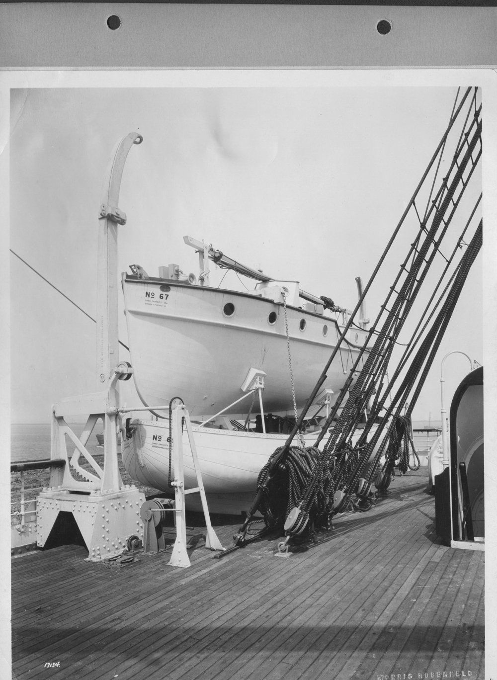
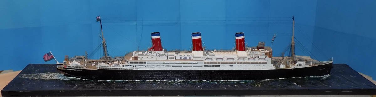
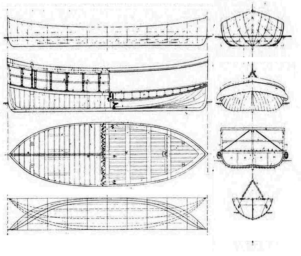
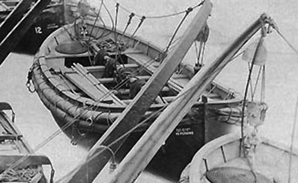
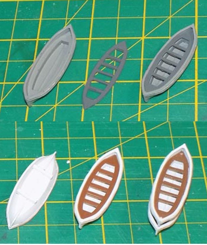
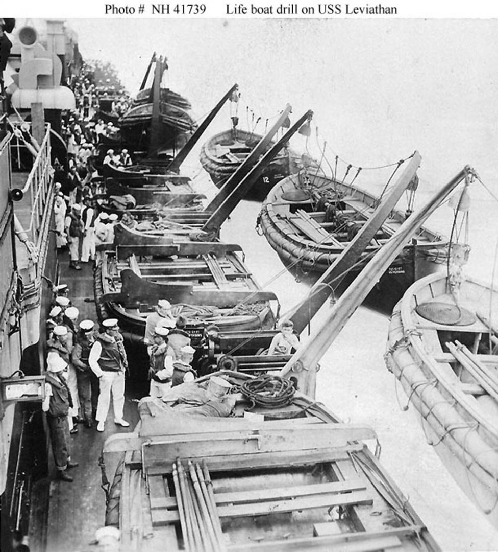
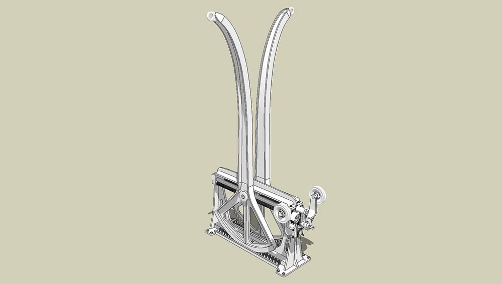
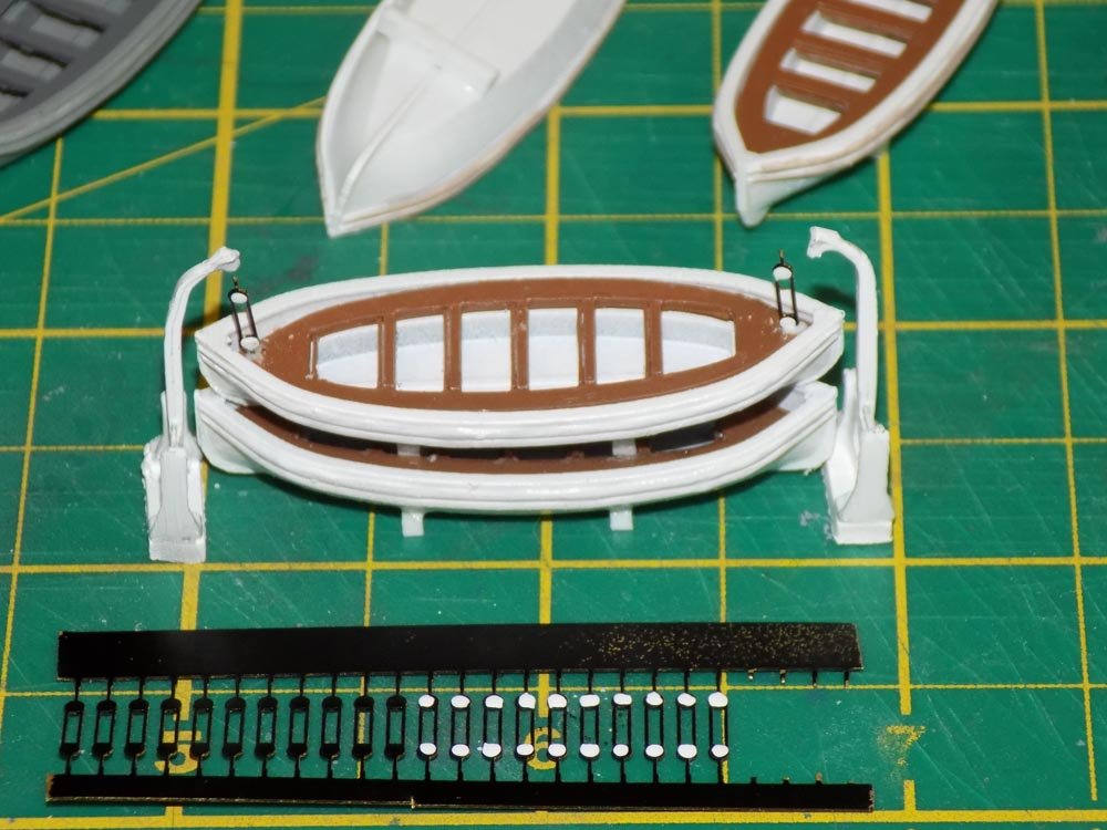
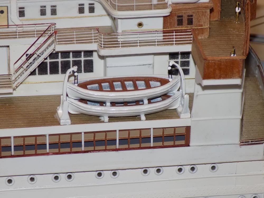
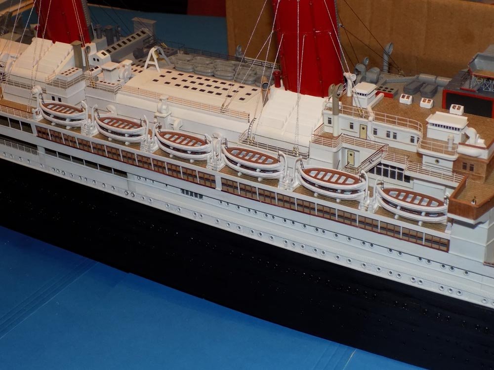
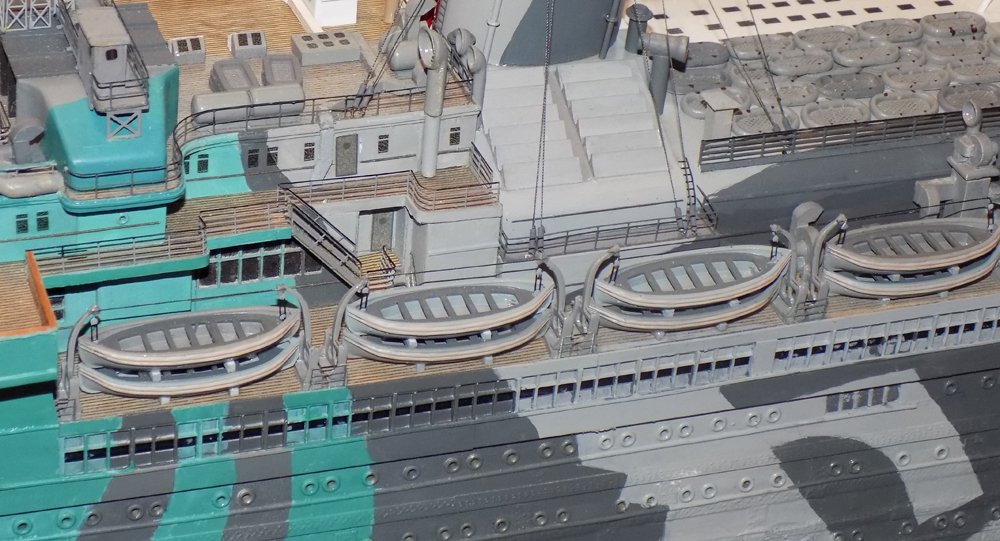
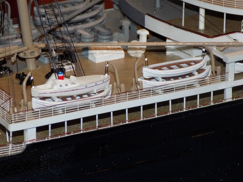
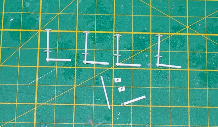
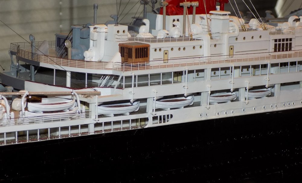
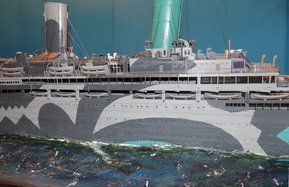
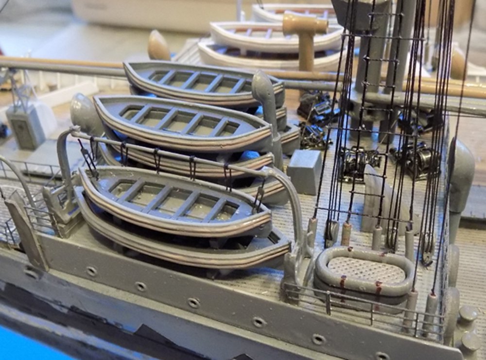
Hi all – Sorry to have been away so long. I somehow developed a bit of writer’s block. Yes, I know that I am one of the last people you would think this would happen to, but there it is. I could name half a dozen possible causes, and maybe they all ganged up on me at once. But I got a bit of energy at the NRG conference, so I am trying to push through the molasses of my mind and post again. Mostly just captions for photos. Fortunately, it did not slow down the actual building process, and the model has been completed, delivered and mounted in the museum. So here are the boats – Over the head of Madam Secretary, with double rolls along the sides. These were canvas sheets used to raise the freeboard. I worked with a designer to have them 3-D printed in 26 foot and 30 foot sizes Their davits, with PE tackle. Mounted aboard ship The larger powered launch Midships boats tucked into the hull, with their external davits The gang of boats on the forward deckhouse I’ll try to post again soon. Dan

- 238 replies
-
- 21
-
-
- leviathan
- troop ship
- (and 2 more)
-
Hi Vaddoc - A very interesting project. You look like you are well on your way. Although it may be a bit late, here are two books in my library that you might want to look at. "Boats of Men of War" by W.E.May. It will have all the details, scantlings and other information on the boat you are building. $10 to $25 from Amazon "The Construction of Model Open Boats" by Ewart Freeston. Construction techniques for several types of boats, including lapstrake ones. $25 - $50 from several sellers. Best of success. I will be following along with interest. Dan
-
Hi Toni - An excellent idea and project. From the look of the finished hull, you are incorporating most of the techniques and details that a ship modeler needs to learn. This epitomizes what I think should be central to the Guild's mission - setting standards for achievement and then teaching and demonstrating how to reach them. I will be following along with great interest. Dan
- 167 replies
-
- 18
-
-
Hi Gary - Outstanding realism, as always. Love the broken window. Maybe you could add some clear tape 'repairs' to protect the crew. Dan
-
Hi Druxey - Is this the one that sold at the Miller Auction Gallery in 2009 for 384,000 pounds? Dan
-
Good day, Mr. Hoving - Like Druxey, I have been a fan of yours for decades. Your techniques have informed my work, and although I have not been called on to build a Dutch sailing ship, all your books are in my library if needed. If I ever get away from the people who pay me to build models, a Dutch 17th century warship is on the short list for a personal project. I am also eagerly following along. Seeing how you improve, replace, or minimize your "mistakes" will be the icing on the cake. Dan
-
Hi Mark and Marc and all - I understand that the oaks of England were specially raised for their curved pieces, especially where the trunk would split or where limbs came off at right angles to the trunk. That is one reason they were marked with the King's broad arrow and cutting them down was treason, punishable by death. Here is a drawing from Dodds & Moore, Building the Wooden Fighting Ship,, a book that I highly recommend. I hope it helps. Dan

-
Beautiful, Rob - I may have missed it in reading your log - how are you laying on your ratlines? They look great. Dan
- 1,208 replies
-
- 2
-
-
- great republic
- clipper
- (and 1 more)
-
Hi John, Jan - Well spotted. I saw the same things, but did not have any concrete answers. I believe that the chains go to the side anchors, but the fittings that they go into (which I do not fully understand) have no exit through the side of the bulwark. The hinged door that covers the fairleads does not extend that far back, so the chains can only go down into the hull. As for the height, I agree that the photos that I posted show the chains lifted off the deck by tension. But others show them on the deck and wrapped around the base of the winch, as I have modeled them. That was the solution that I chose. Thanks for looking in and keeping me on my toes. Dan
- 238 replies
-
- 8
-
-
- leviathan
- troop ship
- (and 2 more)
-
Hi Rob - Just read through your build. I don't know why it took me so long to do it. Excellent work, especially at your scale. Logical, thoughtful, careful - especially the sails. My fingers are crossed that you never go through your recent troubles again. Glad you are back. I'm following along now and I'm looking forward to staying with you till the pennant is raised at the masthead. Dan
- 1,208 replies
-
- 3
-
-
- great republic
- clipper
- (and 1 more)
-
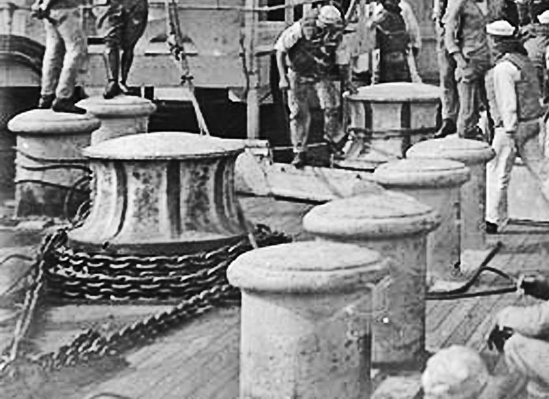
Hi Carl - If you compare the photographs you can see that the breakwater stays aft of the second pair of large bollards. The anchor winch first sits between this pair, then moves behind the breakwater. There are still some open questions about exactly when this happened, but physically it seems pretty clear. Happy to help with any travel ideas. I'm not an expert, but I have done a good deal of travelling and have even managed to visit every one of our 50 states. Dan
- 238 replies
-
- 6
-
-
- leviathan
- troop ship
- (and 2 more)
-
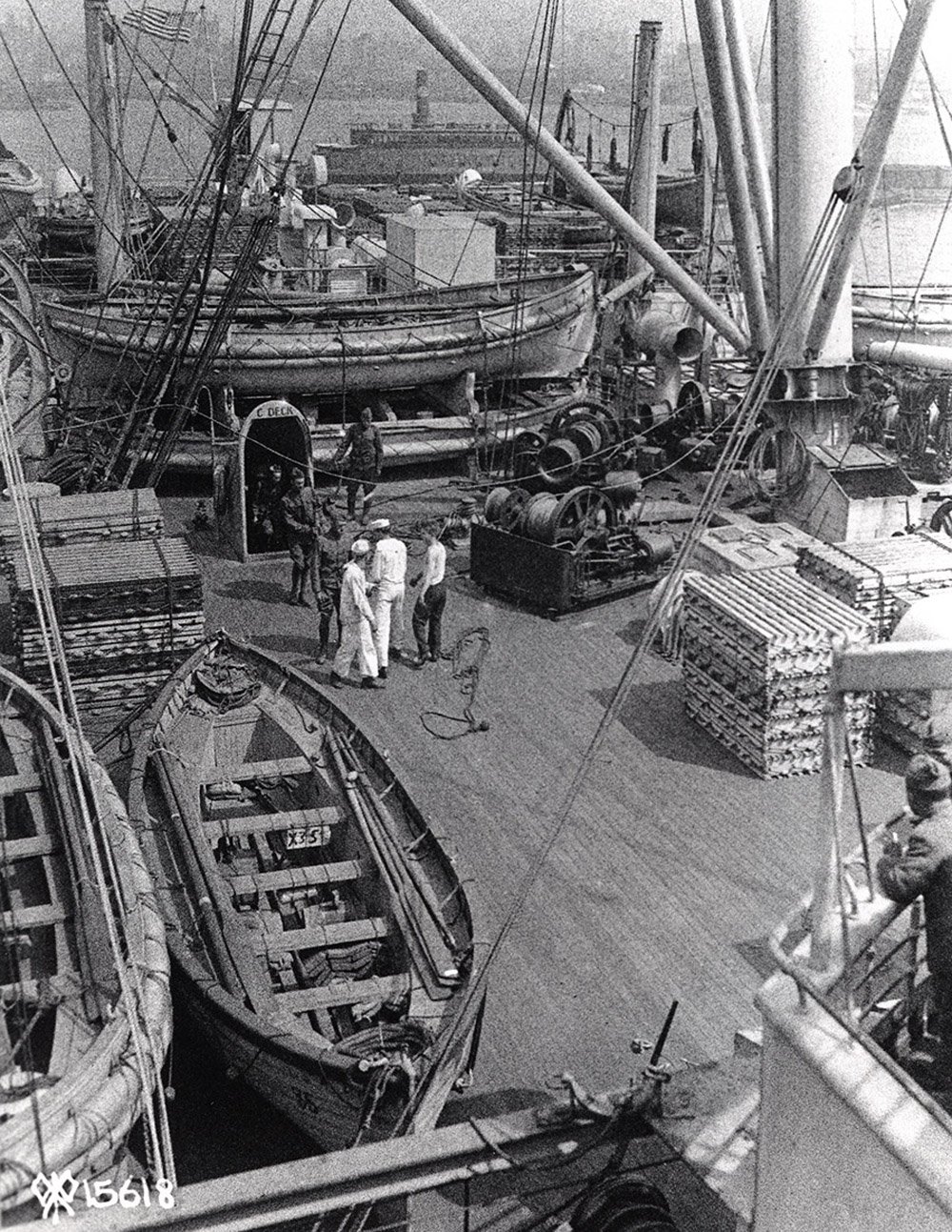
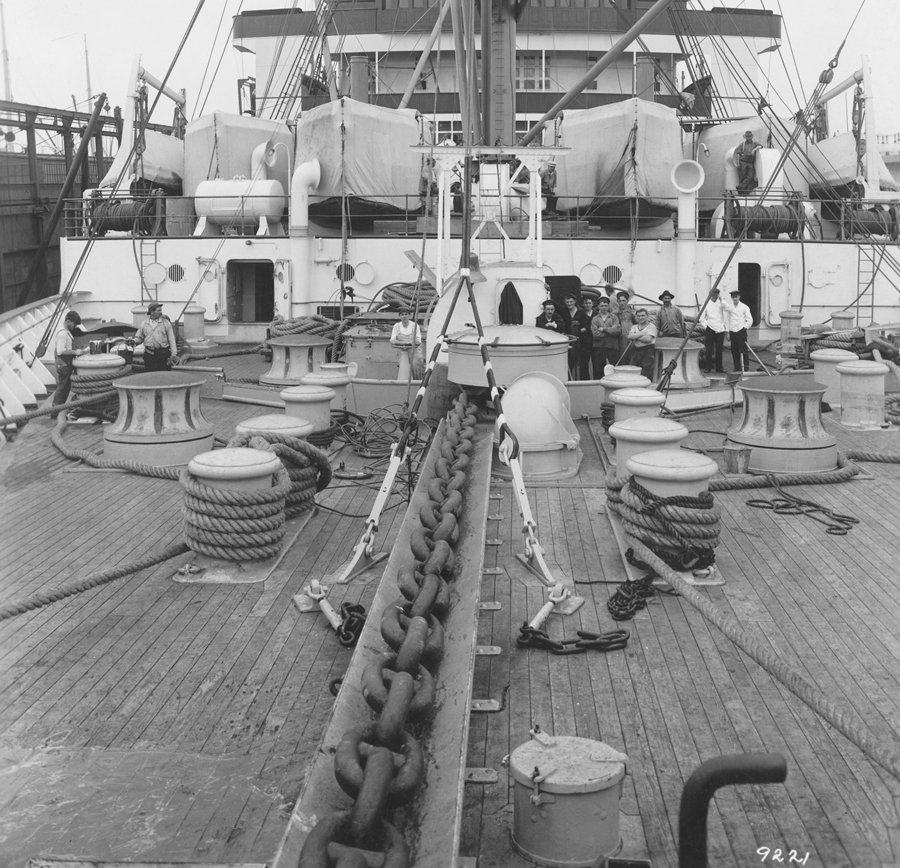
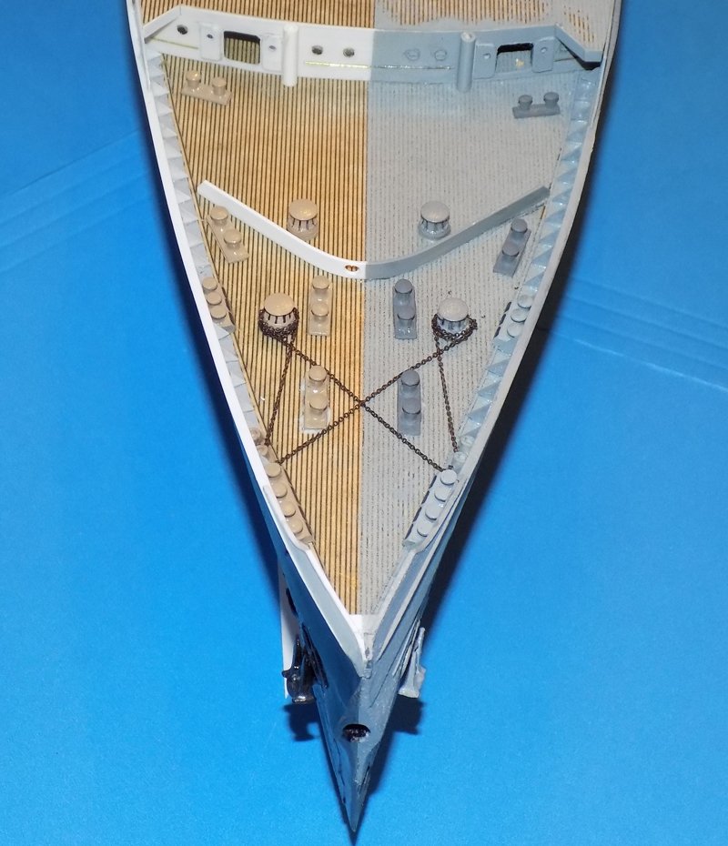
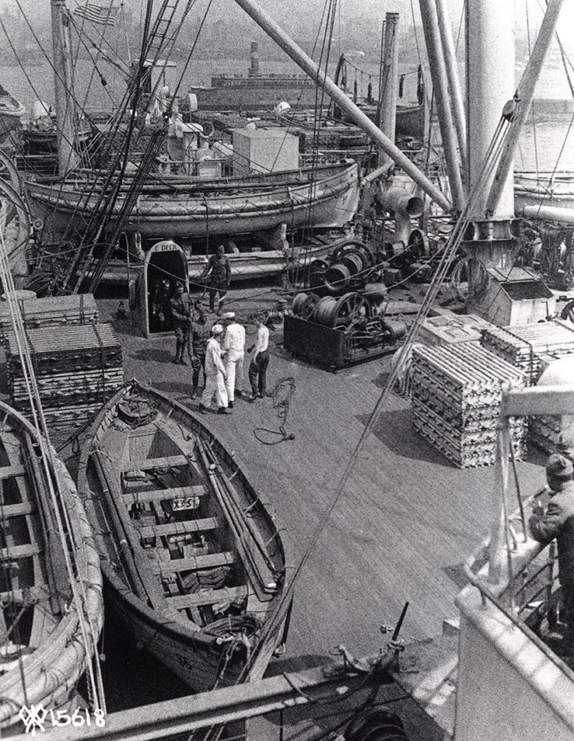
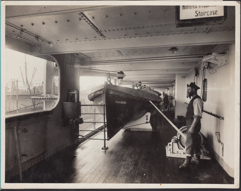
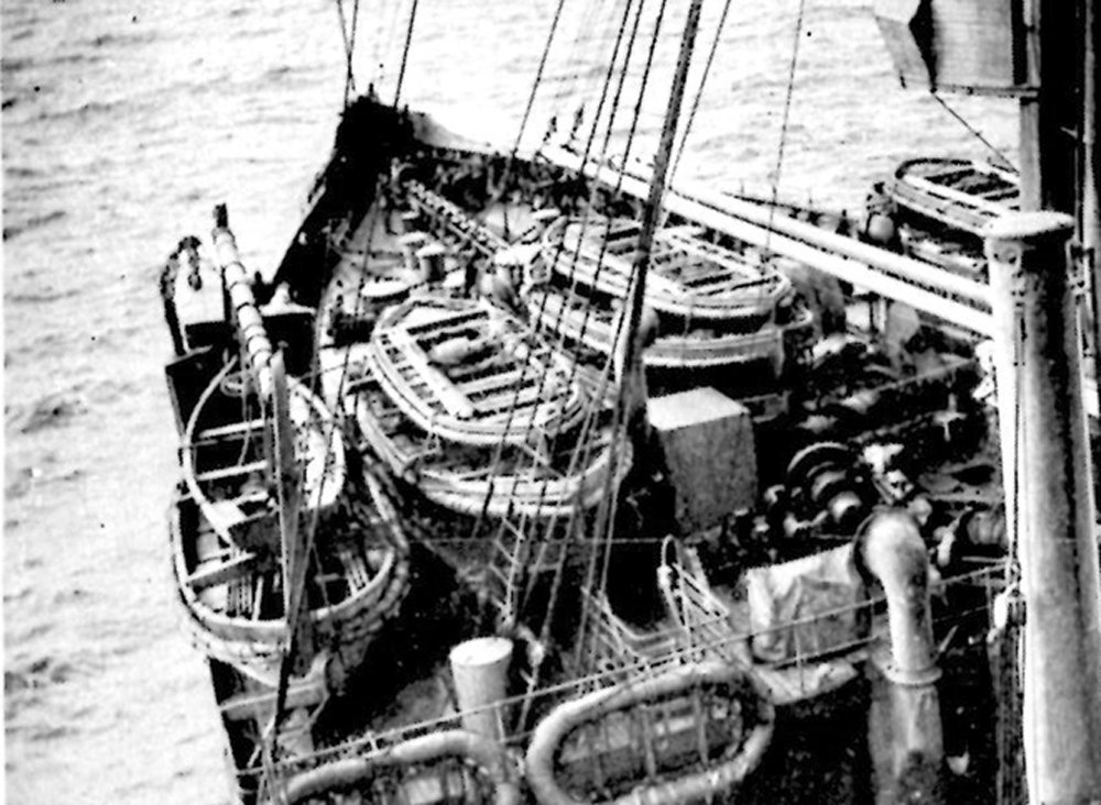
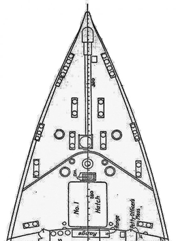
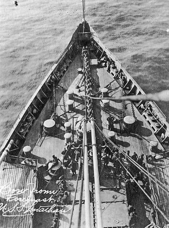
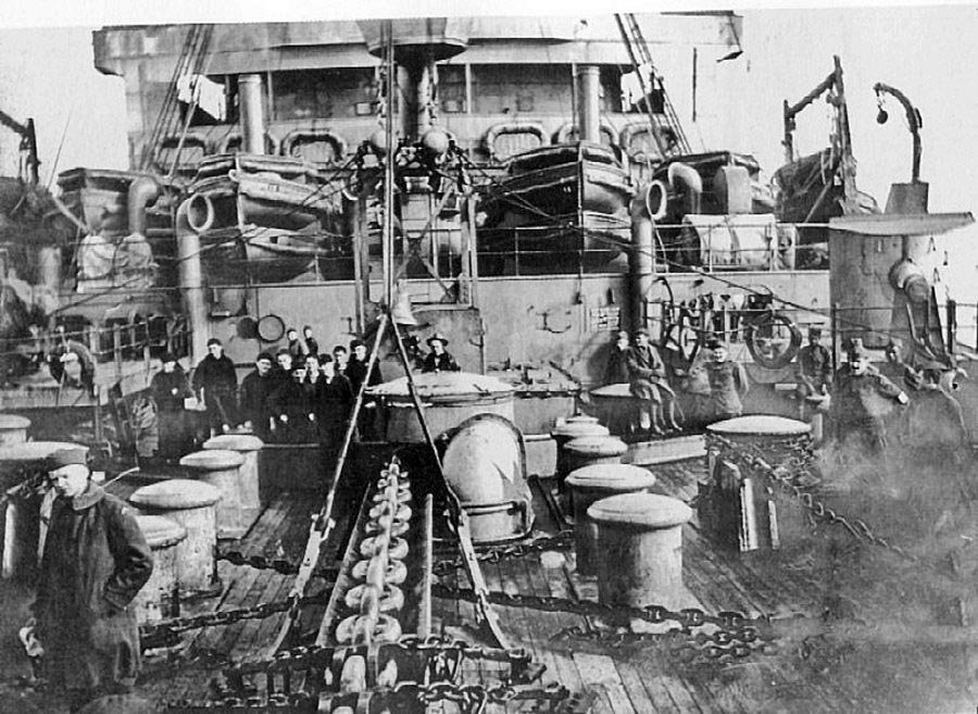
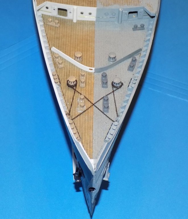
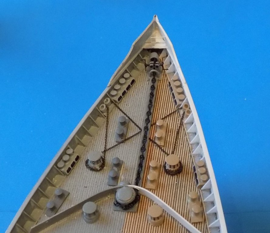
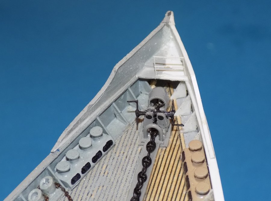
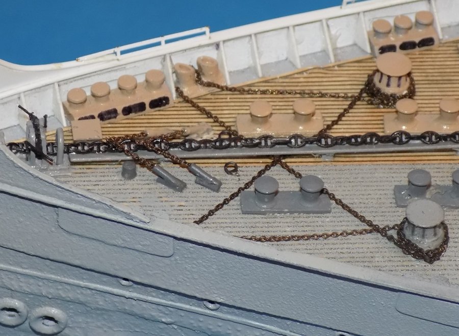
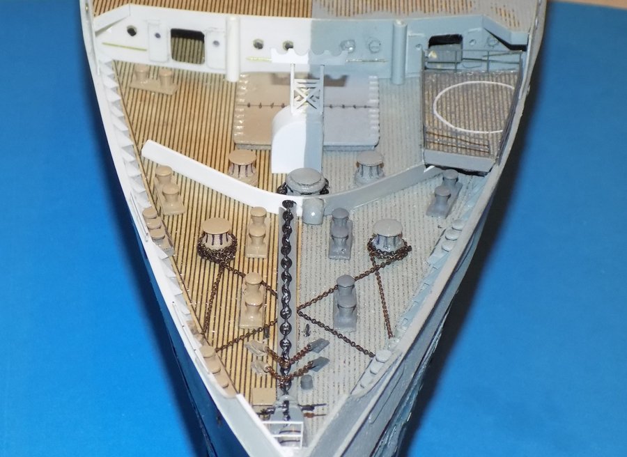
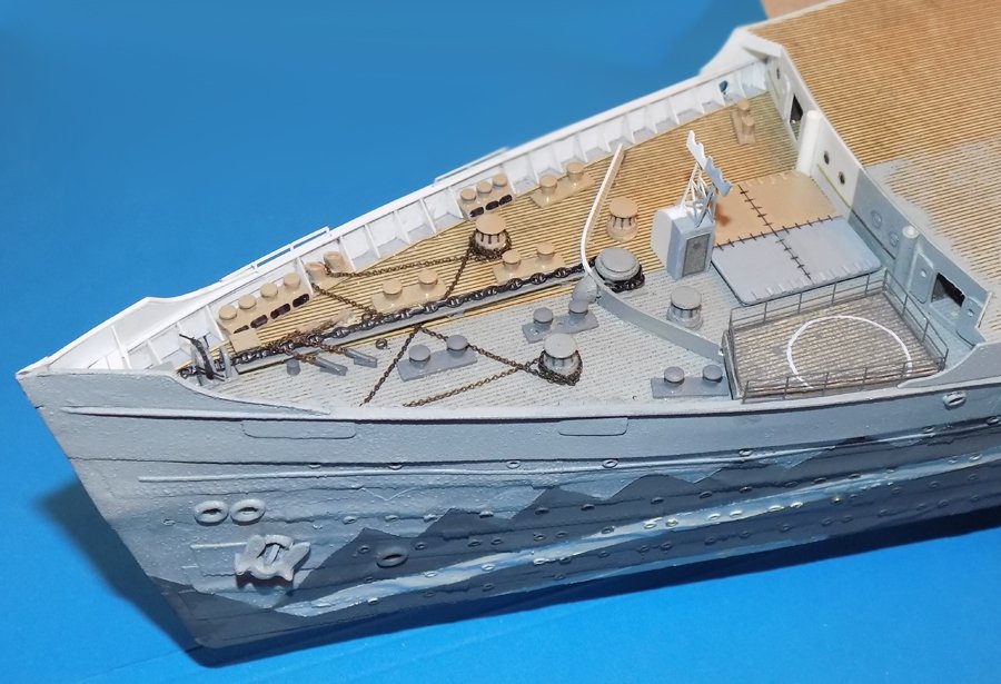
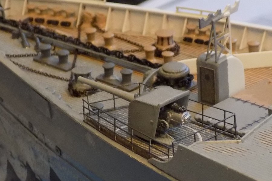
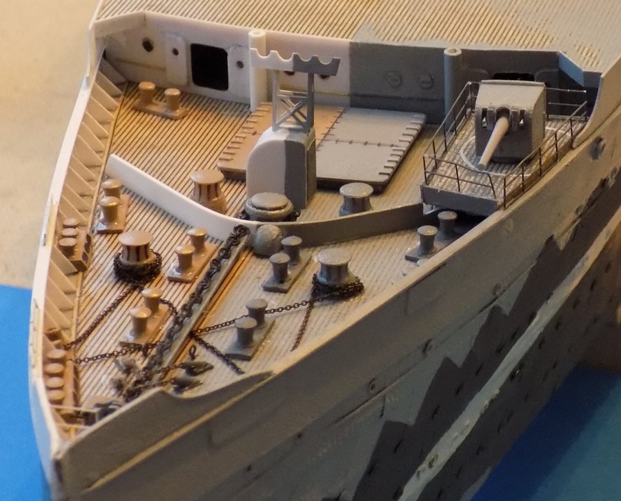
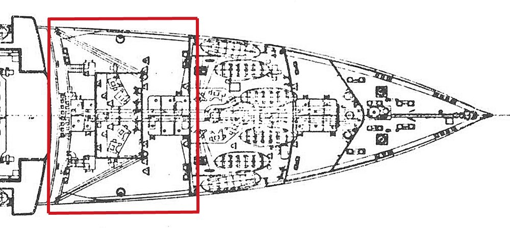
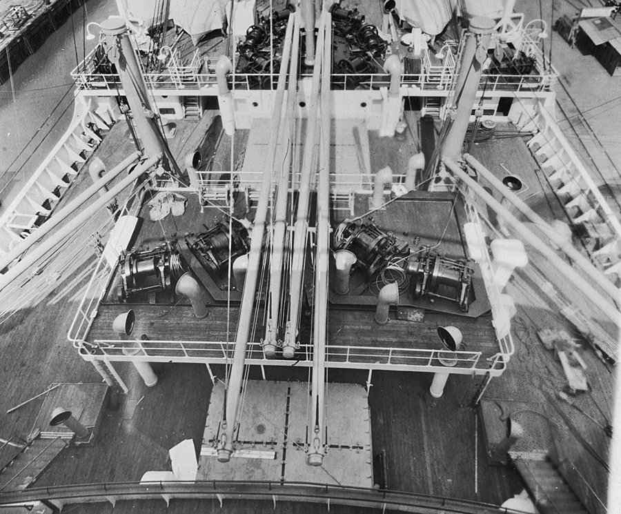
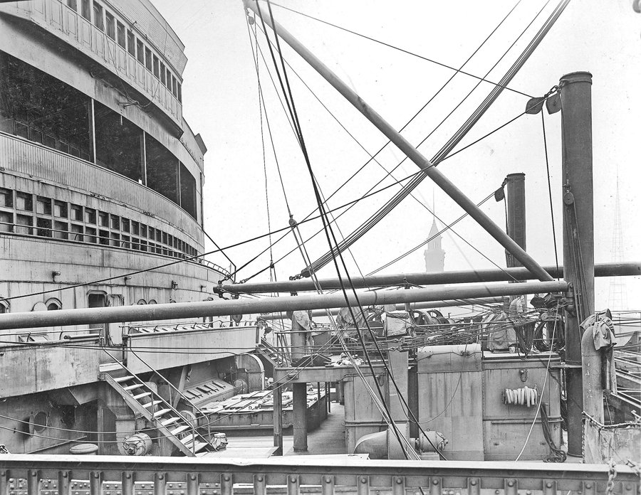
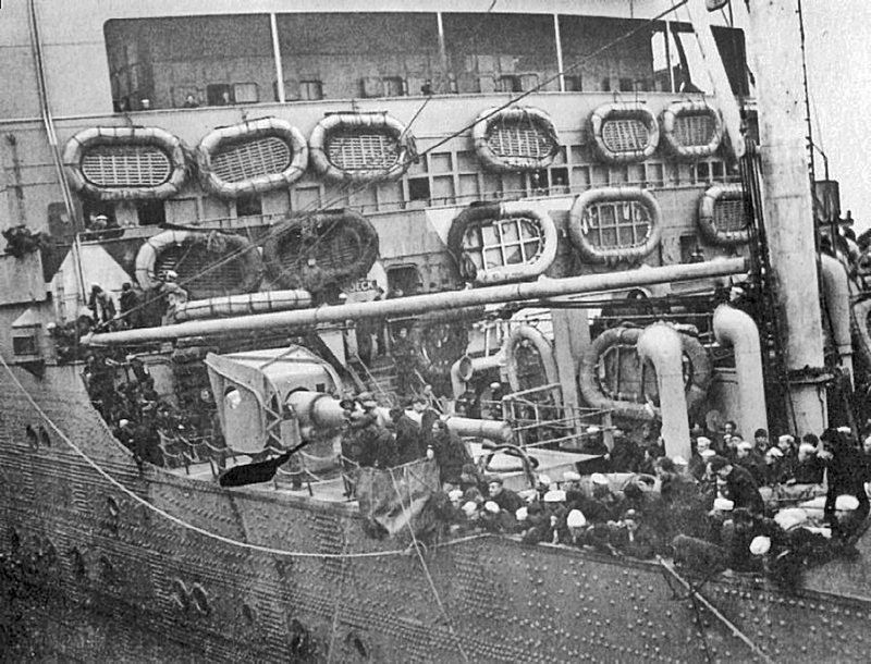
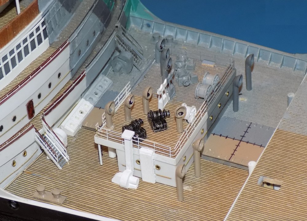
Hello again to all – Thanks so much for the compliments and commiserations. Please don’t take my experience as the last word. Many people that I have talked to, on the boat and after coming home, have had excellent river cruises. Just my luck to get a rainy week. Carl – don’t avoid America as a vacation destination. Some of my favorite trips have been through the Southwest, with its geological wonders, herds of wildlife, and the ancient dwellings and modern cultures of our native peoples. But back to the shipyard - - - The next area of the ship to be tackled was the working deck at the bow. As seen on the plan, there are two sections, bisected by a curved breakwater. Six large bollards are mounted in the forward area, with two smaller ones in the aft section, which also contains a large hatch. The chain for the large anchor at the nose of the ship comes up on the centerline, but then angles slightly to starboard to run around the chain winch which sits between the aft pair of bollards. This agrees with this photo taken, I believe, towards the beginning of the war service. Note that the lighter chains from the smaller winches for the side anchors run under the large anchor chain. Contrast that with this photo. It is clear that the large anchor winch has been moved back aft of the breakwater. The chain runs through the breakwater and returns to the chain locker through a covered chute. This configuration was retained during liner service. After discussion it was decided to use this layout rather than splitting the winch in half. The breakwater was shaped, painted and installed with a hole for the anchor chain to starboard of the centerline. Bollards are Bluejacket castings, cleaned up and slightly modified. The smaller winches are Shapeways offerings, mounted on round bases and painted. The light chains are the finest that I have, with a nominal diameter of 0.020” and more than 40 links/inch. The fittings for the main anchor include a large Shapeways winch with an added base to raise it to the needed height. The trough for the chain, the return chute, and the hawse pipe and chain brake are all scratch-built. A small triangular platform was installed at the extreme bow with the hawse pipe and chain brake below it angled slightly to starboard. The trough was cut and fitted over the side anchor chains to meet the breakwater. The stud link chain is another Shapeways product. I was quite happy with it. It is very accurate and not expensive at all. After the chain was installed the screw drive for the chain brake was fashioned from 0.032” brass rod and installed. The handles are sections of PE railing. Chain preventers were mounted, two on each side. They are made up from the beads that I used for turnbuckles, ground to a shallow angle and mounted on small pads. Short lengths of fine chain nip onto the large chain, although I did not mount preventer hooks. That would have been a detail too small even for me. Low railings are mounted on the bulwarks above the fairleads to help protect the soldiers and sailors who are seen in many photos standing on the fairlead heads and leaning over the side! In the aft area of the deck the large hatch was built up as previous hatches were, painted and installed. Just forward is a companionway with a curved top that straddles the centerline. On its top is a 4-seat boom crutch for the cargo booms that come off the foremast. On the troop ship side the gun platform was built up to fit over the breakwater and bollards so its deck matched the height of the bulwark. Railings run around its inner edges, with a removable one along the bulwark. The 6-inch gun has been temporarily placed on the platform to check location and height. It is a bit of a shame that the photos show the large shield on the gun, which hides the truly fine details of the breech and the loading and aiming mechanisms. That completes this area. I am happy with it, although I see that the short piece of gun platform railing will have to be straightened. Next I turned to the boats. There are almost 100 of them, with several different davit types. More soon. Dan

- 238 replies
-
- 16
-
-
- leviathan
- troop ship
- (and 2 more)
-
Hi guys - Back from the Danube - now known as the River of Death! If you have missed it on the news, a week after we were in Budapest a Viking river cruise ship, almost identical to our Uniworld ship, rammed a smaller South Korean tourist ship with the loss of 33 lives. I saw that very Viking ship along the river just days earlier. The problem was that Europe has had its coldest and wettest spring in 40 years and the river was very high and brown, with tree branches floating along. The current was running at 6-7 knots and our ship made labored progress upriver. Going downriver it must have been impossible to slow or steer the big ship as it approached the crowded lane under the Margareten Bridge. The video of the accident shows the smaller Korean ship being trapped against the bridge piling before turning and being swamped by the impact. One of my travelling companions, who is frightened of the water in any event, now will not even consider another similar trip. Our own trip was uneventful. Much too uneventful. Lots of bus tours with herds of other tourists. Castles from a distance. Churches and monasteries from the inside, whose golden decorations all blur together. The Hungarian Parliament building and the Vienna art museum, both done at a speed too fast to properly appreciate anything. A nice small private concert at the Vienna Opera House, but in a small side room. No access to the main hall, considered one of the most beautiful in the world, on a par with La Scala. Salzberg was nice, and there was an interesting visit to a farm that grows saffron. I enjoyed watching us go through several locks on the river, but my companions all slept through them. The ship was nice, the food was good, the service was excellent. Otherwise, save your money and buy a good video travelogue. Anyway, glad to be home. Back to modeling in the next post. Dan
- 238 replies
-
- 10
-
-
- leviathan
- troop ship
- (and 2 more)
-
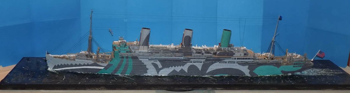
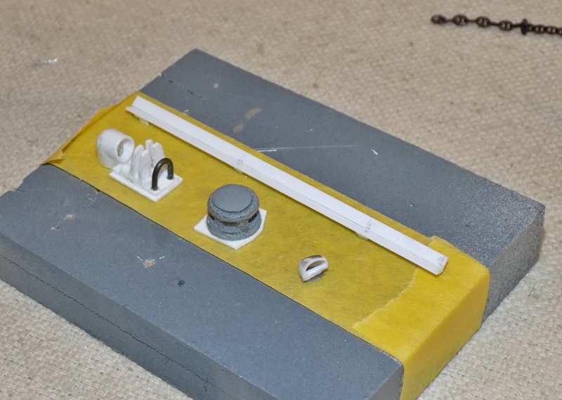
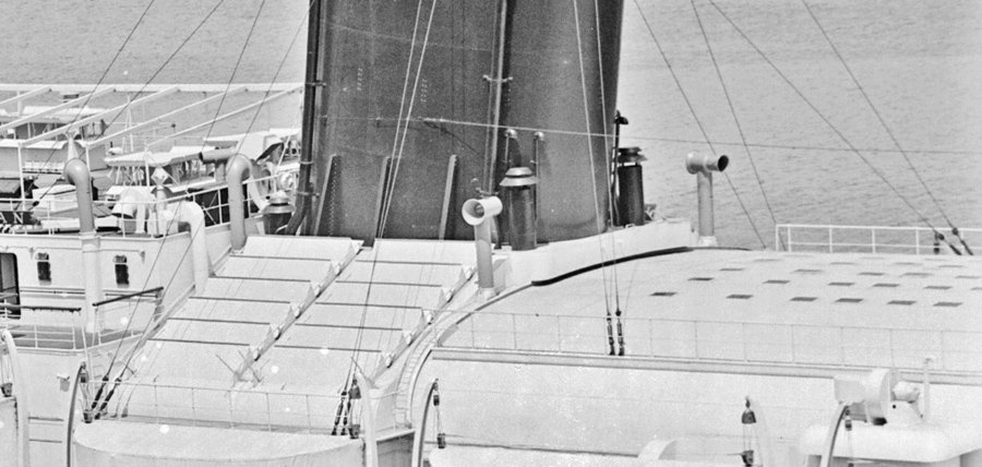
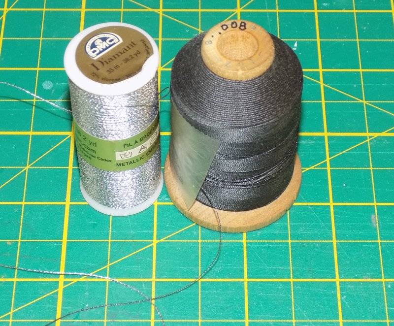
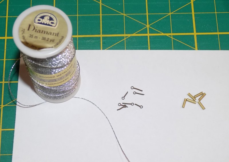
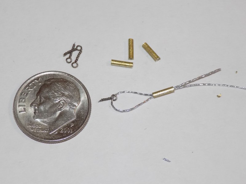
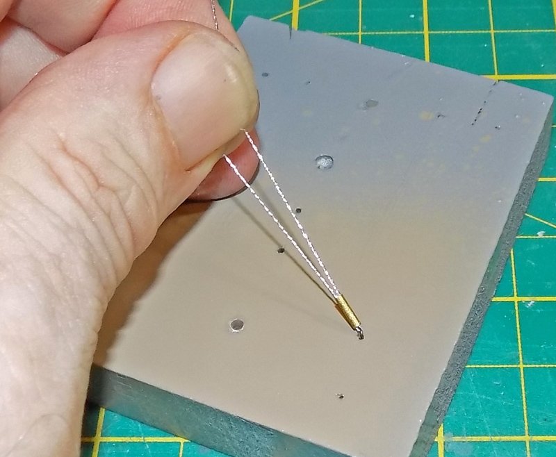
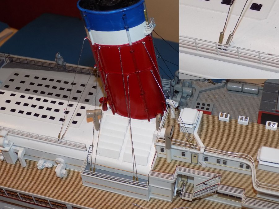
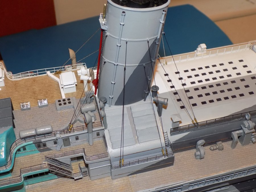
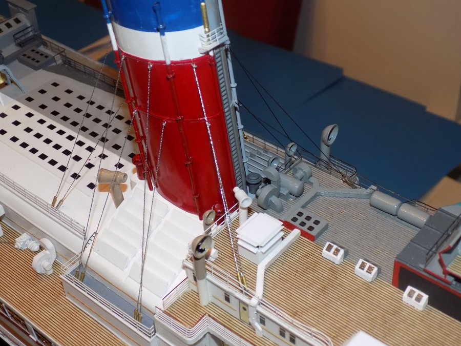
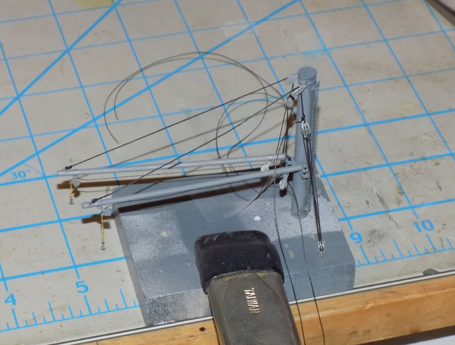
Hello again to all – Thanks for the compliments and likes, and for the comments and critiques too. The more feedback I get, the better the final model will be. This will have to be a quick one. I am going on vacation tomorrow for two weeks and will be cruising up the Danube between Budapest and Munich. I will be looking for points of maritime or modeling interest along the way. I am sure to get my fill of beautiful churches and historic castles and scenic town markets. Back in the shipyard – With most of the detail work in the center of the ship already done, I added the guy wires that support the funnels. None of the photos of the ship are detailed enough for me to determine whether they would have been different colors during the two service periods. Besides, depending on the background, they change color anyway. I decided to do them in contrasting colors, with dark line for the troop ship and bright steel for the liner. For steel I have previously used an actual stainless steel beading wire, but it is unwieldy and difficult to get tight and straight. Any kink, no matter how small, is hard to get out. This time I tried silver metallic thread for the liner side. To get the wires taut I first needed small eyebolts, which I made up from 0.011” wire twisted around the shank of a 0.020” drill bitt. To stand in for the turnbuckles I used ¼” long by 1mm o.d. beads that were sourced from a beading supply house called Fire Mountain Gems. They have a surprisingly large number of products and tools that are useful in ship modeling. The wire is threaded through the bead, then through the eyebolt, then back up through the bead. To install it, the eyebolt is glued into a predrilled hole, taking care not to glue the wire or the bead. The long end of the wire is tied to an eyebolt on the funnel, then the short end is pulled up through the eyebolt until the line is taut. The bead is slid down till it seats against the eyebolt. With tension still maintained, a drop of cyano locks everything together. Here I am working on a simple test bed to see if the thread will bend tight enough around the eyebolt. With this method the 48 wires for the funnels were set up. The result is a bit simplistic, but the wires will always remain straight and tight, which I think is the most important thing. More improvements to the system will be worked on to get the turnbuckles looking more realistic. The troop ship side was rigged with dark line. I initially installed them with the brass colored turnbuckles, as in the photo. However, I did not like the look, and they have since been painted grey, which solved the problem. On the liner side, however, the silver thread did not work out quite as hoped. It looks good in moderate light, but in strong light it is much too shiny. I have dulled it down with matte varnish, but I think it is still too bright. I will show it to the powers that be for their opinion, but I will probably overpaint with steel grey enamel. That will have to wait until I get back. Until then, be well. Dan
- 238 replies
-
- 15
-
-
- leviathan
- troop ship
- (and 2 more)
-
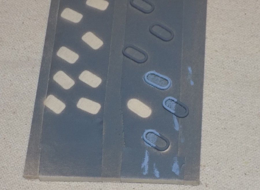
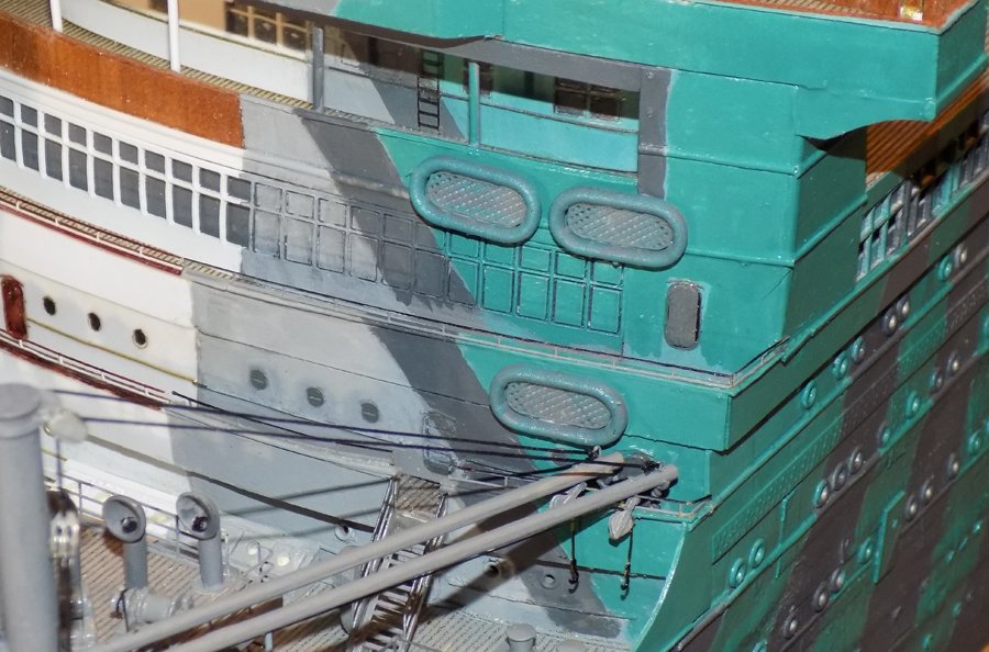
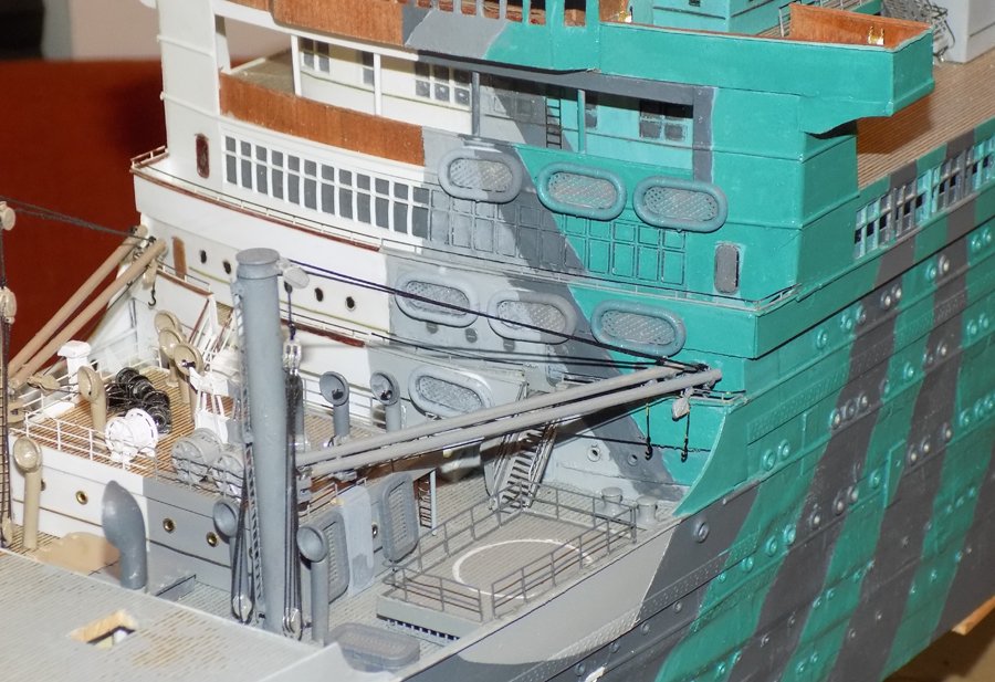
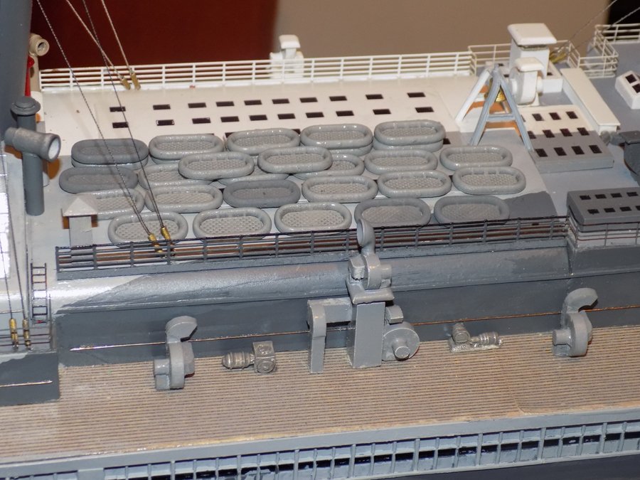
Hi all - Just a quick post to finish up the foredeck well area. The only things left were the Carley float life rafts. They have appeared in some of the earlier photographs of the troop ship. Although there is a record of a plan for their distribution, I have not been able to get a copy from the National Archives. However, I don’t think its absence will make much of a difference. The photos show some floats hanging against mis-matched areas of the camouflage, so they must have moved around a bit. The basic principle seems to have been to put as many as would fit in as many areas as would not interfere with the working of the ship. I guess they figured that if the ship was torpedoed in a combat zone it might be a long time before rescue. And since they knew that most of the casualties from the Titanic were from hypothermia, they tried to get as many life rafts into the water as possible. In keeping with the semi-scratch nature of the model, I found acceptable units already in production at Shapeways. They come in sets of multiple numbers, so the cost was not prohibitive. [I tried to import an image from their website, but couldn’t get it to work.] I trimmed them from their sprues and gave them a coat of grey primer. This also worked for the dark sections of the camouflage. Where the floats sat over other colors they were hand painted using a dry brush technique on the mesh floors. On the face of the superstructure the floats were initially attached with tacky white glue. When this was dry they were further secured with cyano. Looking back, I should have installed them before the cargo cranes went on. The lower floats were quite hard to position in the cramped space. I decided to leave them a little crooked. I think it reinforces the impression that they are temporary. I leaned two small ones against the entryway house. Two larger ones stand up near a stack of three. I also installed the twenty nine sit on the roof of the main hall. There will be many more all around the ship. More soon. Dan

- 238 replies
-
- 12
-
-
- leviathan
- troop ship
- (and 2 more)
-
Mark - yes, I'm happy with how they came out. Figuring out building solutions is a big part of the pleasure for me. Michel - glad to have you following along and glad you are enjoying the journey. Carl - yes and no. The larger cable is 0.010" thread, which is 2" full size. A bit thicker than technically accurate, but in the ball park. The thinner line is 0.006" The problem is that by contrast the first looks thicker than it is. I will probably tone down the visibility later, but that will depend on how the shrouds and other rigging come out. It won't matter the actual diameters as long as they all look consistent. Thanks for raising the issue. Dan
- 238 replies
-
- 4
-
-
- leviathan
- troop ship
- (and 2 more)
-
Thanks, everyone. Druxey - I though of it as designating the troop ship one. As long as I remembered that the one with the spot got painted grey, I was home free. After that there was no confusion. Keith - a whole day named for me? I am honored. And lucky to find those views. Other areas of the ship were never shot so clearly. Nils - actually, I have slowed down a bit. The government shutdown a while ago has cancelled the exhibit where this was to be the centerpiece. Now there is no deadline at all. I will not dawdle, but there will be no 15 hour days either. More soon. Dan
- 238 replies
-
- 8
-
-
- leviathan
- troop ship
- (and 2 more)
-
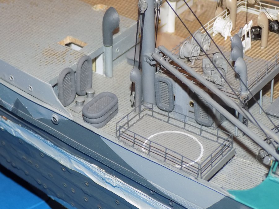
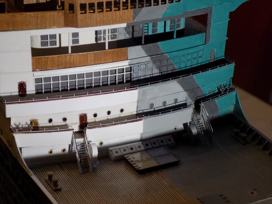
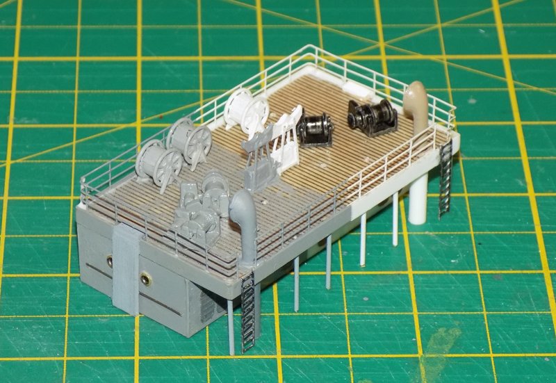
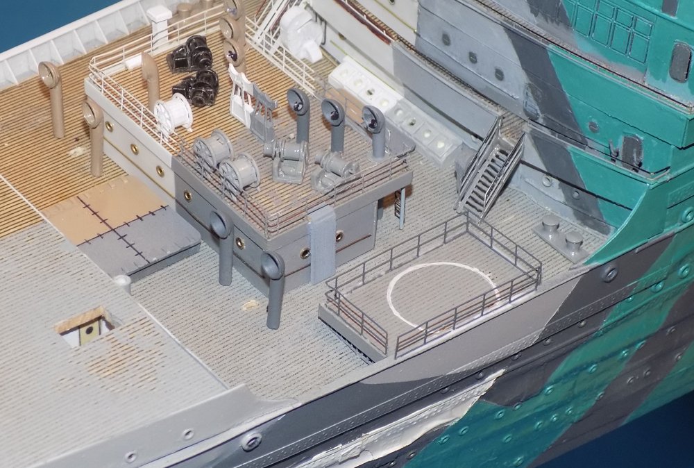
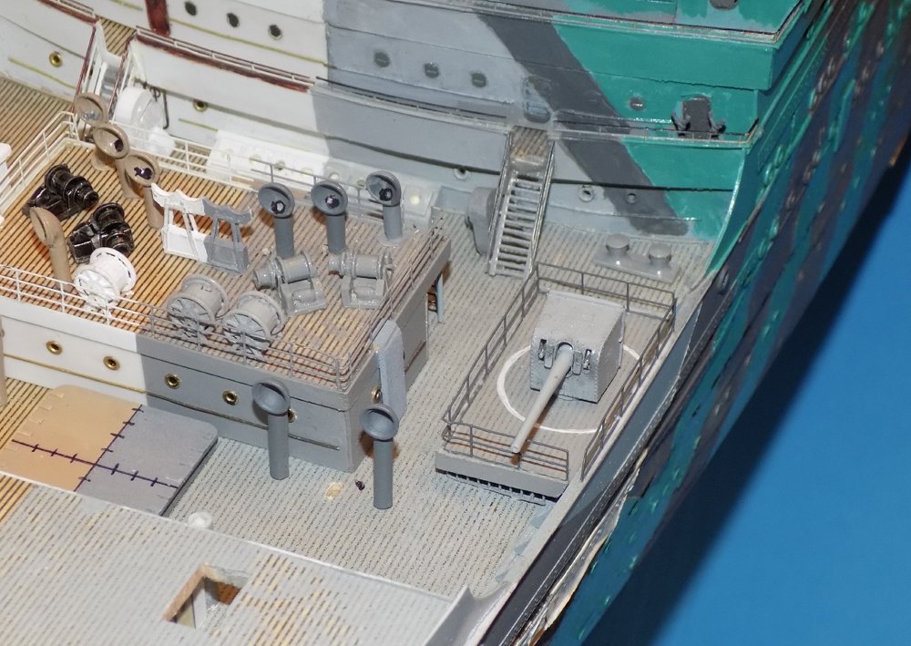
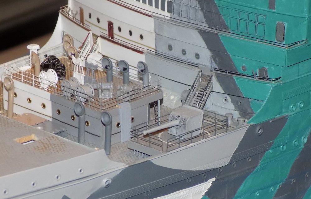
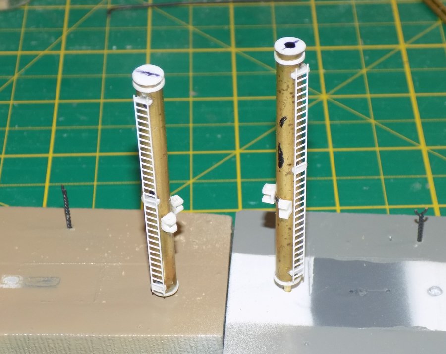
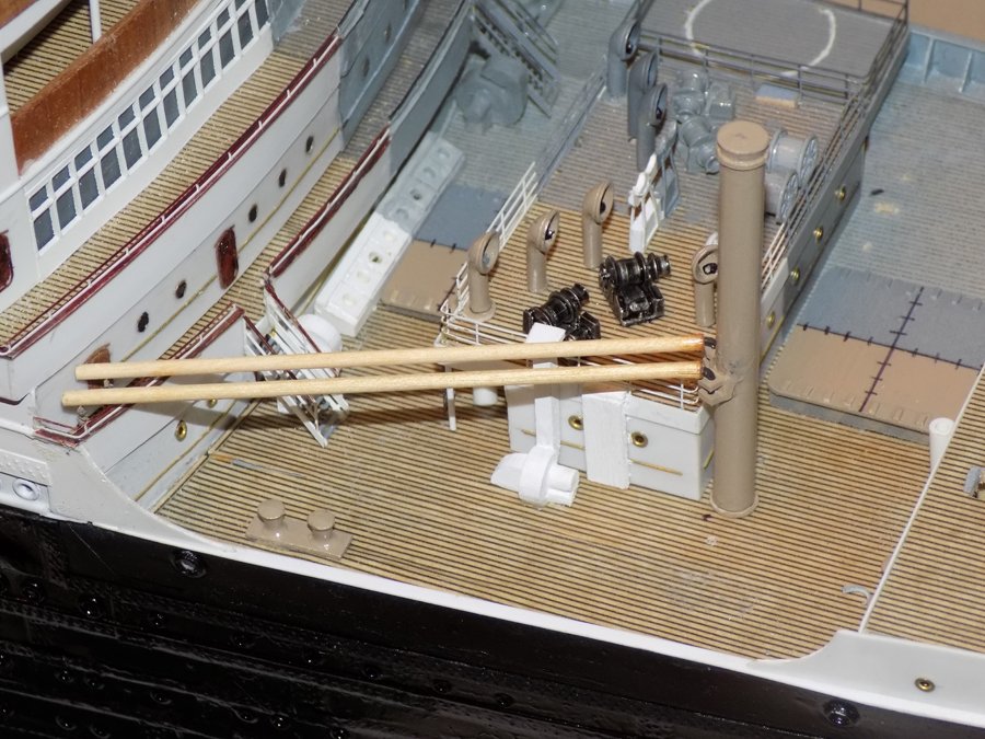
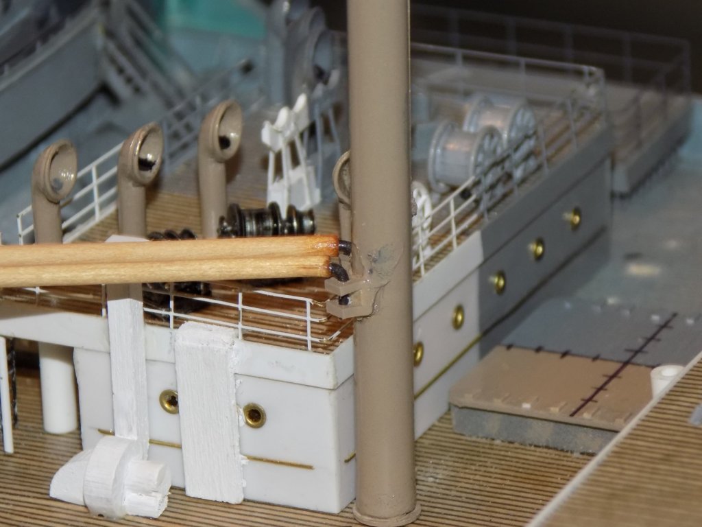
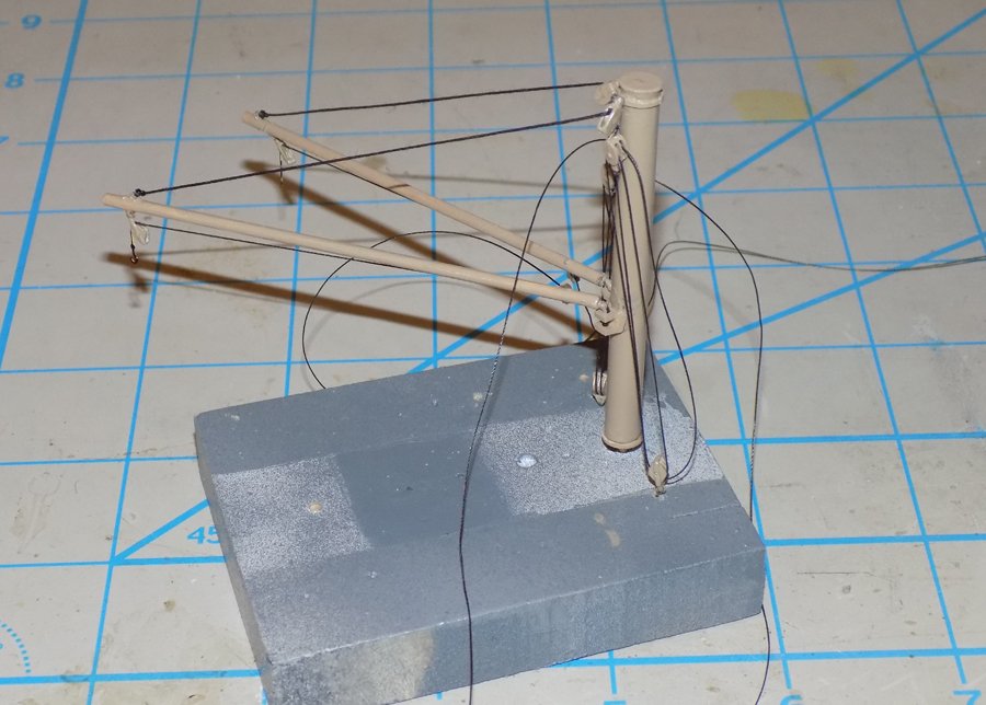
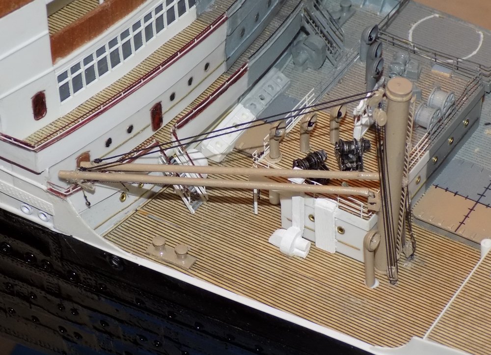
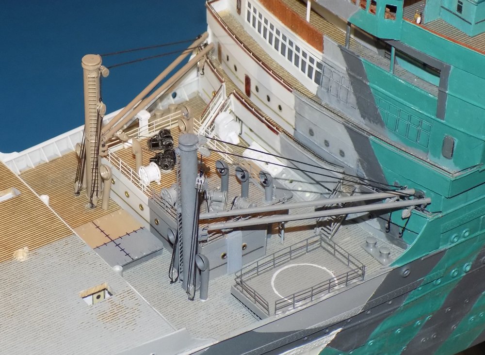
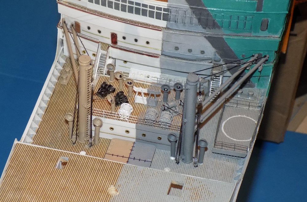
Hello again to all - I hope everyone had a good holiday with family and friends, as did I. It was also good to see old friends and some nifty models at the Northeast Joint Clubs conference. But enough fun . . . back to the shipyard and back on schedule. Another Sunday and another posting. With the bridge completed work moved forward into the well of D deck between the superstructure and the forward deck house. On the plans it is the highlighted area. It contains the third-class passenger entryway, two cargo hatches, and two cargo cranes with two booms each. I rounded up some decently detailed photos of the area from the ocean liner era. And a precious few from troop ship times. The two biggest differences, of course, are the life rafts hanging from the railings and the six-inch gun on its built-up platform. The face of the superstructure was almost complete already. I just had to add the handrails to the tops of the solid railings on B and C decks. On D deck two blowers sit with their motors under the stairways. The hatches were detailed with small bits of plastic strip to indicate the hinges. The entryway was previously constructed back in November to test spaces and sizes. Now I went ahead and detailed it with ladders up to the roof and railings around it. The steam winches are Bluejacket castings. The hose reels are Shapeways 3-D printed products. The central fitting is a scratch made crutch for the four large booms that come off the foremast. Several more cowl ventilators were added in a vee pattern taken from the plans and photos, as was a long-necked blower on the starboard side only. The ventilators just forward of the deck house were inserted only temporarily until the cargo cranes were installed. On the troop ship side the gun platform was built up, decked, and railings were installed. The white warning circle was spotted in only a few photos, but I thought it was a nice touch. The gun is from Shapeways. It is a shame that the blast hood hides the truly fine detail of the breech mechanism. I will be drilling out and darkening the muzzle of the gun before it is installed permanently. The masts for the cargo cranes are brass tubes with a plastic base and cap. There is a reinforcing ring near the top for the boom lift blocks. PE ladders were added to the inward side of the masts. To keep them aligned I drew a guide line on the cap. To keep me from confusing the port one from its starboard partner I put a large dot on its cap. The cargo booms were cut from appropriately sized hardwood dowels. At their far ends they sit on crutches twisted up from wire, made as I do with eyebolts, but here the top of the eye ring was removed to make a landing cradle for the booms. The inward ends of the booms were strengthened with cyano, then drilled for 0.040” iron wires that were bent into a tight L to form the gooseneck joints. The ends of the wire were slid through holes in the clevis fittings that were cut from strips of U-channel styrene. The mast and booms were set into holes in a scrapwood fixture so it could be worked on more easily. Large single lift blocks were fitted with wire posts and secured through the reinforcing ring and the brass mast. The boom was fitted with a small eyebolt on top of its outer end and two small single cargo blocks below. For each boom a heavy line was run from the end eyebolt and through the lift blocks at the top of the mast. The running end of the line was seized onto a double block just below the lift blocks. A lighter line ran from the becket of the double block and was laced through a matching double block secured to the deck. The mast was secured to the deck and the boom ends glued into the support crotches behind the C deck rails. The lower double blocks were secured into the deck and all lines were tightened. Under the outer ends of the booms a PE cargo hook was bent around the sheave of the cargo block. It will be straightened so it looks to hang naturally once all the installation is complete. The same configuration was built up for the troop ship, just painted grey rather than buff. This second cargo crane was installed and rigged like the first. The final task was to run the lines from the cargo blocks to the drum heads of the four steam winches and secure them there. Other than installing the cannon, which will be one of the last things that gets done, this area is now complete. Next task – making and lacing the guy wires for the funnels. I need 16 for each, a total of 48. An ocean liner is a continuous evolution of repetition, repetition, repetition . . . Until then, be well Dan
- 238 replies
-
- 13
-
-
- leviathan
- troop ship
- (and 2 more)
-
Hi Gary - Yes, I see what you mean. I wonder why there would be heat exchangers on the flying bridge rather than nearer the engineering spaces, but I agree that they were probably not air intakes. Whatever, your knowledge and experience are far greater than mine in this area. Thanks for commenting and sharing. Dan
- 238 replies
-
- 4
-
-
- leviathan
- troop ship
- (and 2 more)
-
Hi Nils - She is a pretty little thing. I'm sure you will do her justice. I have pulled up a chair and am anticipating some entertaining hours ahead. Dan
-
Hello Karl - It is always a good day when I can watch you build another model in your excellent style and workmanship. I will be following along until the end. Best wishes for success from an American friend. Dan
- 87 replies
-
- 2
-
-
- royal caroline
- yacht
- (and 1 more)
-
Hi Marc - A very quick skim of VdV paintings have English ships with only the lower wales painted black. The French do seem to take this style up higher, so I agree with your color choices. Below the lowest wale the black color is not, I think, a boot topping, but is part of the 'black stuff' which goes down to the keel. It was one of the earlier teredo worm prevention systems before coppering. I recall reading that many formulations were tried, mixed into tar to coat the bottom, some of them including human feces. There was also 'white stuff', but I think this was developed later than the SL. This does not affect your colors, of course, since yours is a waterline model. Just a bit of trivia. Dan
- 2,699 replies
-
- 3
-
-
- heller
- soleil royal
- (and 9 more)