shipmodel
-
Posts
941 -
Joined
-
Last visited
Content Type
Profiles
Forums
Gallery
Events
Everything posted by shipmodel
-

Roter Löwe 1597 by Ondras71
shipmodel replied to Ondras71's topic in - Build logs for subjects built 1501 - 1750
Hi Ondras - Beautiful work. The new ropes came out especially well, with a nice tight and regular lay to the lines. One small point of wording - the curved deck fitting is not a wheelhouse. The Roter Lowe would have had a whipstaff, not a wheel. The fitting is actually a cover for the man who operated the whipstaff, sometimes called the helmsman. The opening in front is so that he can see the set of the mainsail and hear commands from the navigator and captain. To bring his head up above the height of the deck he just stood on a box. Sometimes the simple solutions are the best. Here is a drawing of the whipstaff from E. Keble Chatterton's book -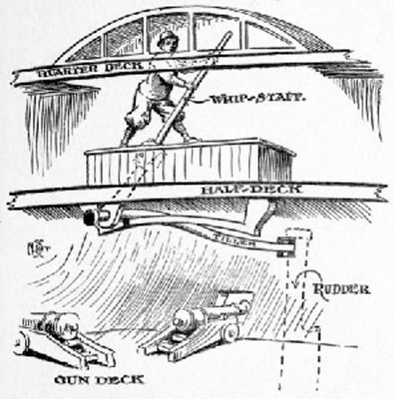
-
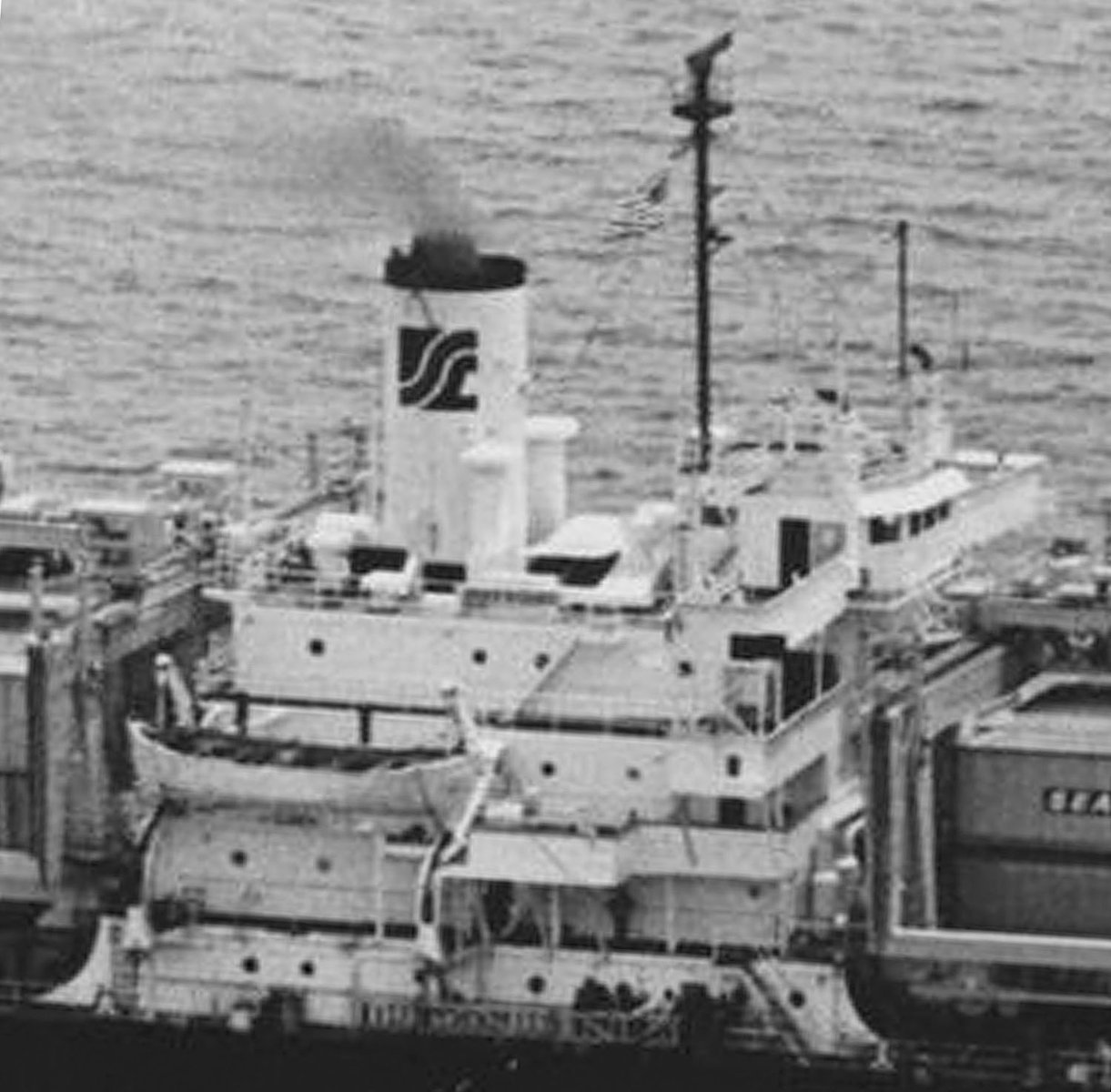
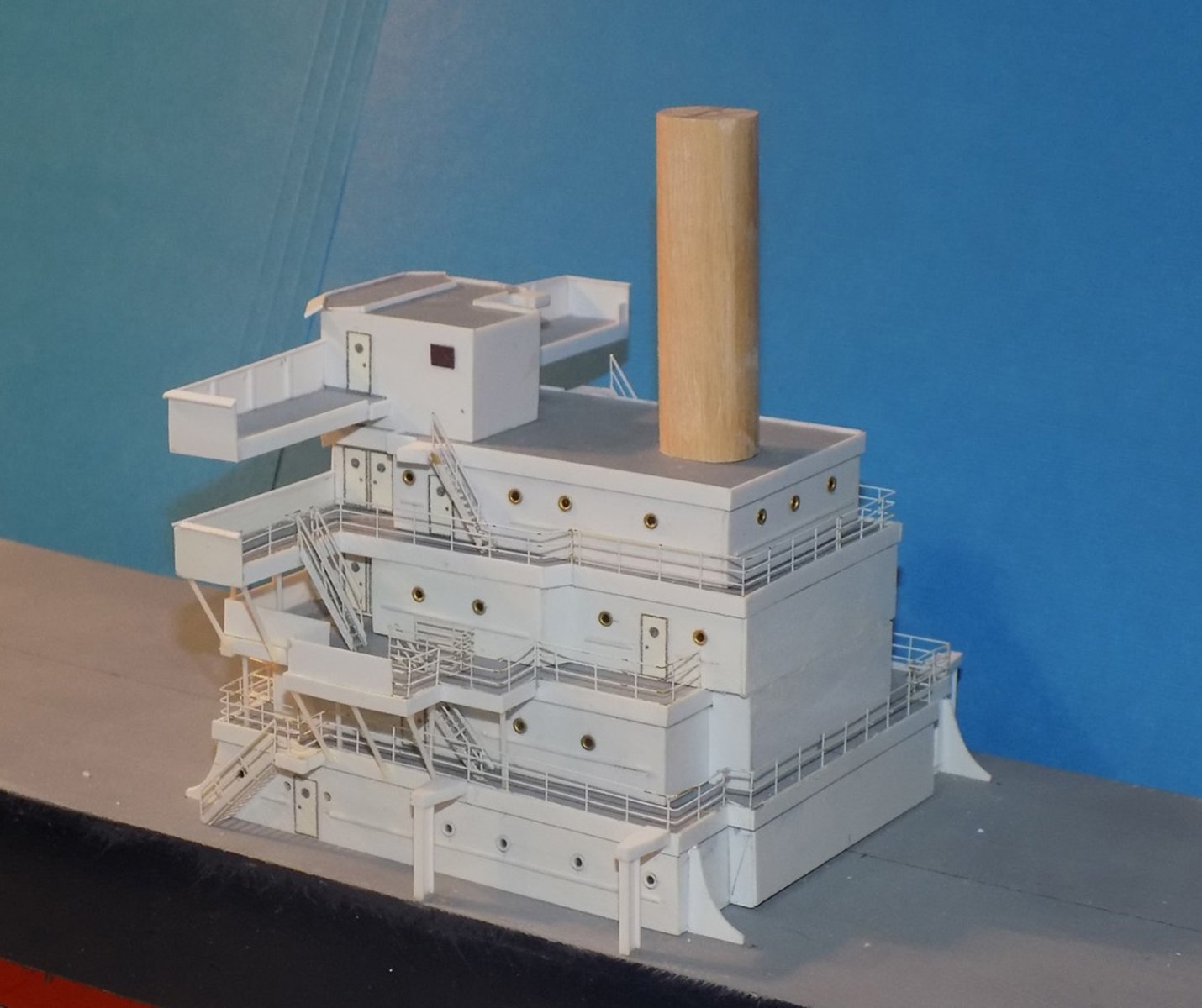
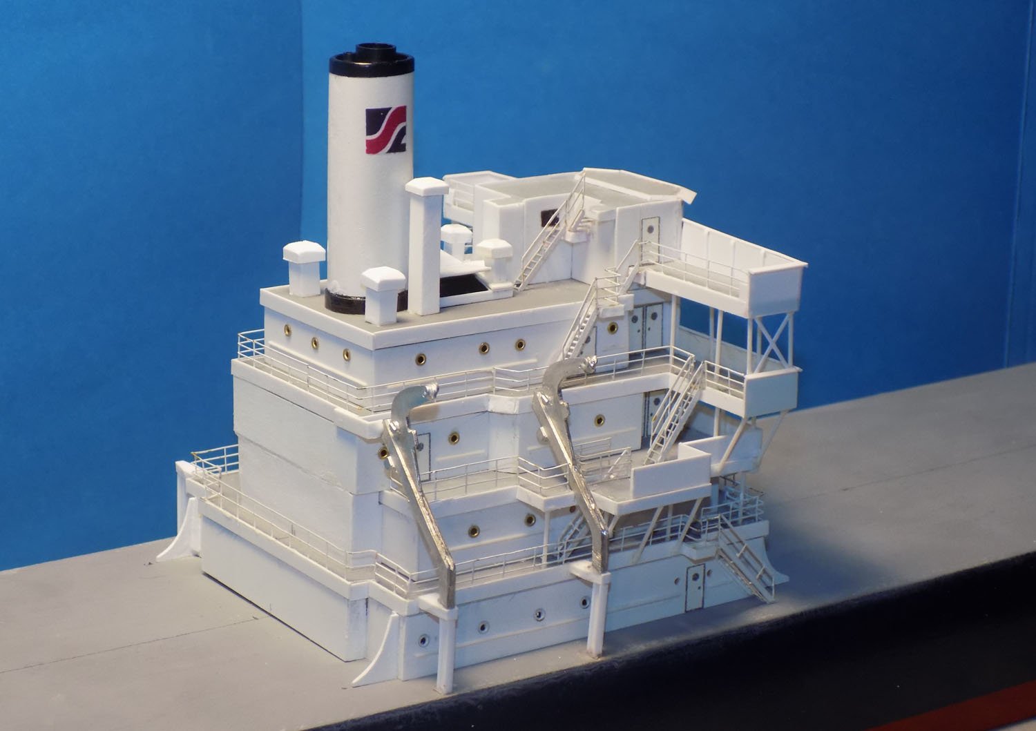
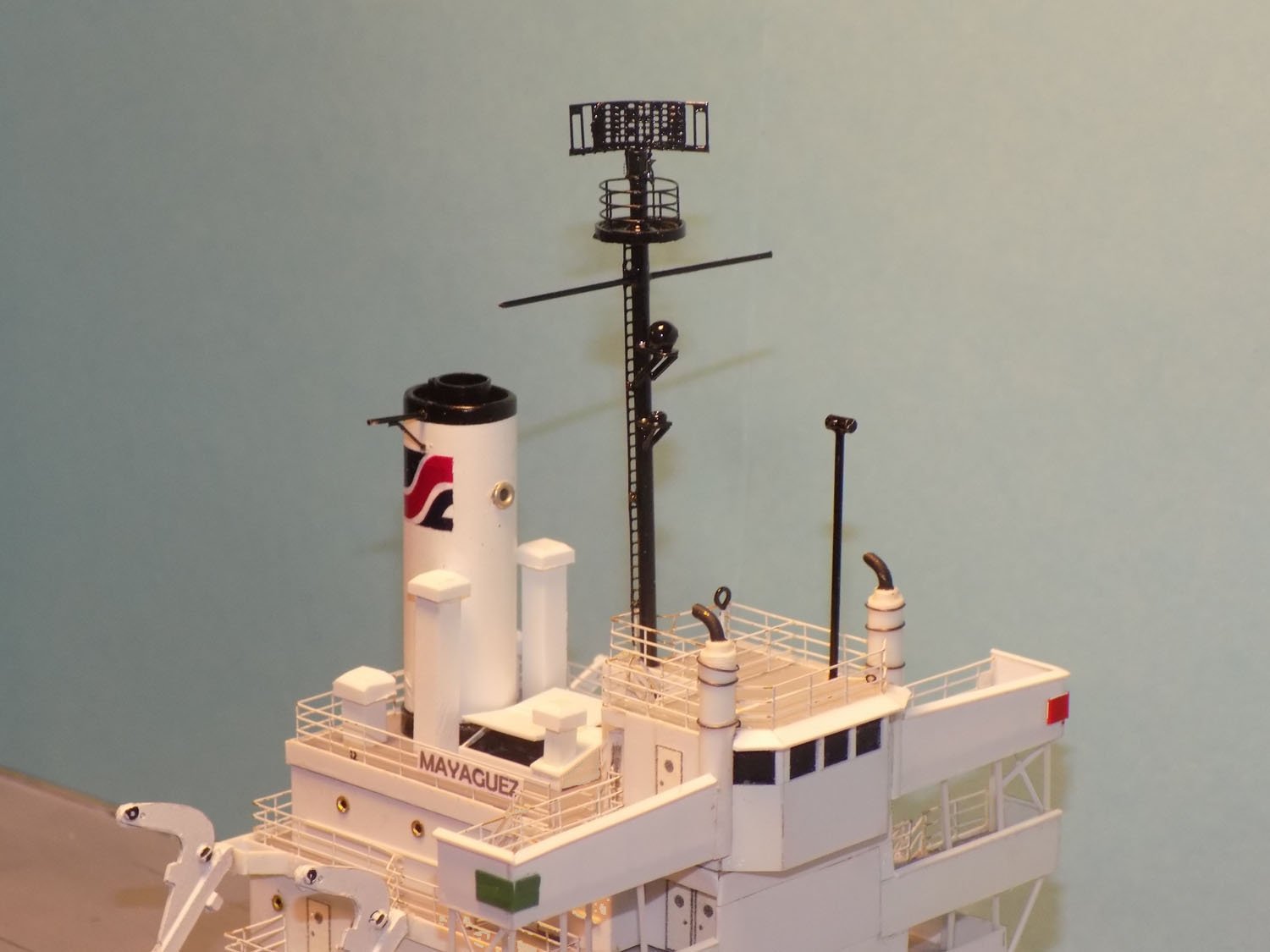
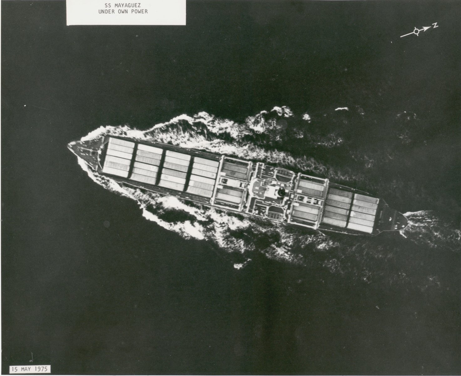
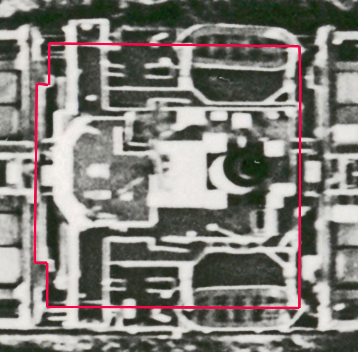
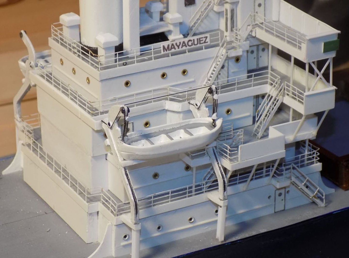
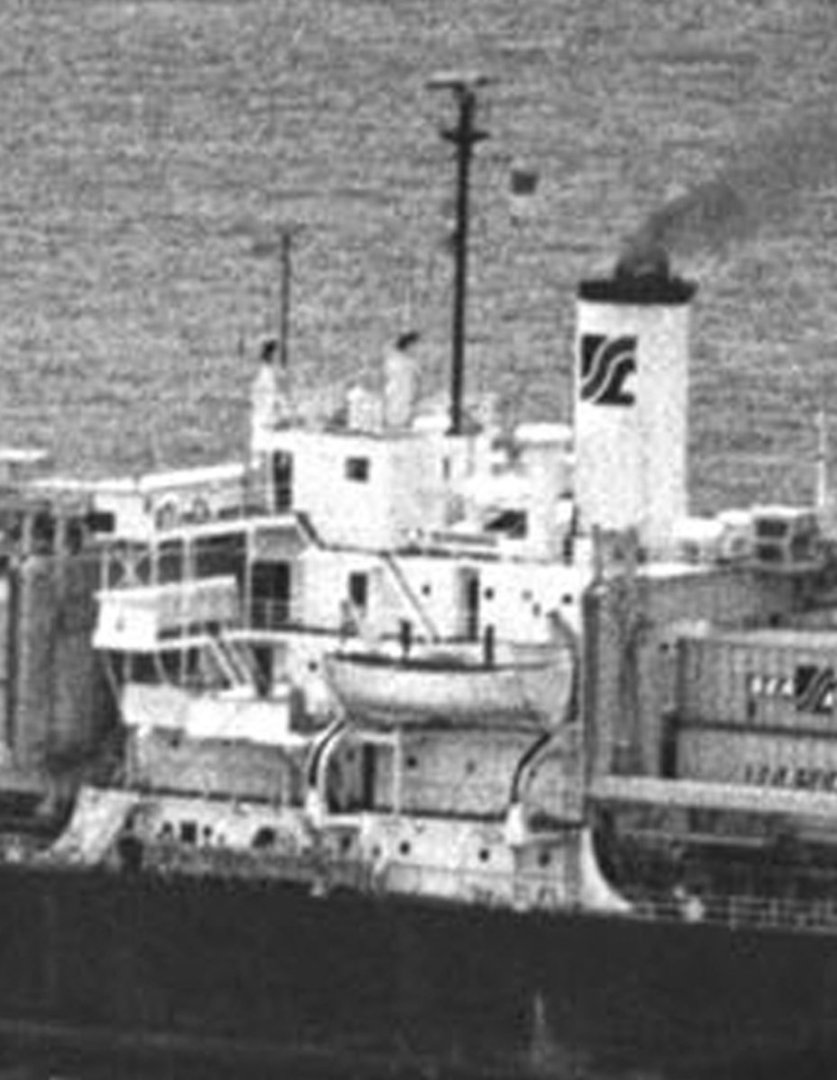
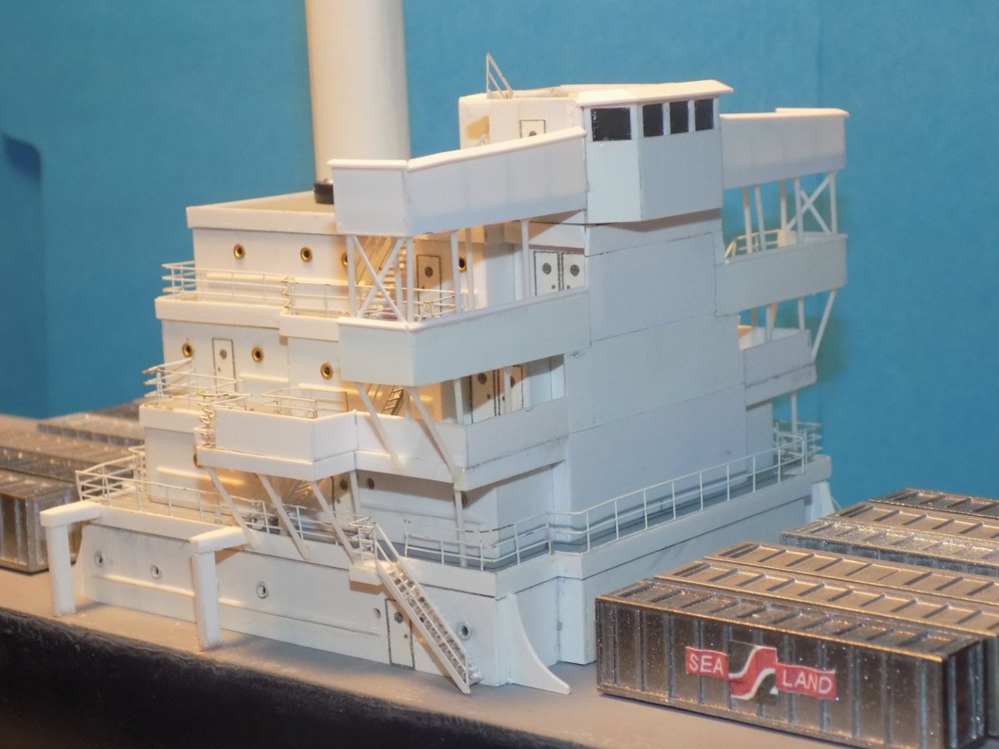
Hello again to all – Thanks for the comments and likes, as always. It has not been that long since the last segment, but since this is a retrospective of the build I can get another one out quickly, as long as I have time left over after the honey-do list. This one is a bit wordy, with only a few photos since I concentrated on building and not taking photos of my progress. I hope that the explanations will be sufficient. In the second segment, posted a while ago, the superstructure was in the middle of construction based on the available photographs. To remind you, here is a close-up of the best photo of the superstructure and a ‘plan view’ taken by a US Air Force plane from almost directly overhead. At that time all of the decks and deck houses had been built and the doors, handrails, ladders, and railings for the lower decks had been installed. The structures of the top two decks and the bridge had been built up but not detailed. Next the funnel was built. It started with a ¾” birch dowel that was carved down to an oval cross section. The dowel was wrapped in 0.02” styrene attached with gel cyano. The seam was not positioned along the aft centerline but was offset to one side. I find that even after filling, sanding, priming and painting there can be a slight imperfection in the surface. I think that it is less noticeable if it is not centered, which is where most people look. A reinforcing collar was made for the bottom of the stack from 0.015” strip, painted black. At the top the photos seem to show that there is a narrow lip enclosing a large round exhaust fitting and a much smaller pipe, probably for excess steam. A homemade decal of the SeaLand logo was created in my printer and applied to both sides of the funnel. Actually, this decal ultimately looked too small so you will see a larger one in future photos. Directly ahead of the funnel is a large, square fitting. I could never be sure of its shape or function, but in one of the fuzzier photos there is a hint that it might be a raised hatch with open doors on either side. The interior can’t be seen at all, but could contain filters for an air intake. I modeled it that way but I ask anyone who has a better idea to let me know. I believe that the six capped square tubes that stand alongside the funnel are the exhausts for the ventilation system. Their relative heights were taken by comparison with doors and railings in the photos. They were made slightly overlong, then trimmed to a height that ‘looked right’. The lifeboat davits were Frankensteined from two cast pewter fittings from Bluejacket. The top arm of a 7/8” davit could be ground to a thinner profile that closely matched the photos. But the slides were not long enough since the deck had been widened and the lifeboat had to travel further to reach the edge. I cut off the foot of one fitting but cut the second fitting higher up the slide. Mating these two gave me the length that I needed. They were secured with a bit of brass wire across the joint then filled and glued together with an epoxy product called ‘JB Weld’ that has metal particles in it. I find that it gives one of the strongest bonds across small metal mating surfaces. The detailing of the upper deck and bridge continued with the large radar mast. It was built up from a length of 1/8” brass tubing with a 0.032” brass rod crossarm for the signal flags. A PE ladder leads up to a round lookout platform with a bit of PE railing curled around a dowel to fit. A radar dish was fashioned from several PE fittings. Although it looks good and matches some photos of the ship, further examination of the photos taken during the incident showed that the radar at that time was a solid bar. This radar was removed and a more correct one was built and will appear in later photos. Four guy wires made of fly tying thread were installed later. Two small exhaust stacks were fitted to the forward corners of the bridge house. They were cut and carved with slots opened down their lower ends to fit over the forward bridge solid railings. Small sections of plastic tubes were heat bent then trimmed and painted black as exhaust pipes. Final details include a smaller simple mast seen in the photos but whose function I don’t know. A radio loop was bent up from brass rod and installed as well. PE railings were fitted around all the deck and bridge wing edges and nameboards were printed with a type face that matched those seen in the photos. To get a sense of the sizes involved, the nameboard is just over 1/16" tall. The lifeboat davits were made more accurate by sawing grooves in the integral sheaves where the lifting lines will run, then the channels in the slides were filed open and square. The davits were painted white with the sheaves and slide channels painted black. A Bluejacket casting of an open lifeboat was filed smooth and painted. After the lifeboat was installed over a square section support the lifting lines with PE blocks and tackles were run. A final line runs at the top from davit to davit for support. A final detail of coiled hanks of rope hung from this line will be installed later. And here is the superstructure with all the final details added, such as the running lights, the guy wires, and the signal flag hoists with an American flag flying. In the next segment the bow and stern decks will be detailed. Till then, stay safe and well. Dan


-
Terrific work, Keith - As one who has struggled with making and hanging sails, I am truly astounded with how well yours came out. No need for a third hand when your two do such great work. Dan
-
Hi JKC - I find that the GMM railings are quite sturdy, although they will kink if mistreated. If a bar is bent it is easily nudged back into shape and stays straight. I also have some from Tom's Modelworks and agree that they are fragile. But they are useful when I need light railings. I have used Tom's sets of deck chairs and benches for the Titanic and they are great - highly detailed and in scale. I use smooth, flat jawed pliers to do all the bending of PE details. Folding is done against flat wooden blocks. Never with my fingers except for long, smooth curves. I think that I detailed my techniques in the build log of the SS Andrea Doria. Best of success with your projects. Post your build log here so I can follow your progress. Be well Dan
-
Michael - I also missed your post about your hand injury, my friend. Glad to see you back, and hope that your recovery was complete and satisfactory. Be well Dan
-
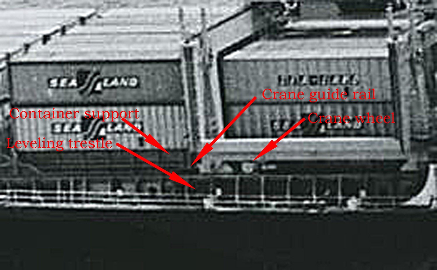
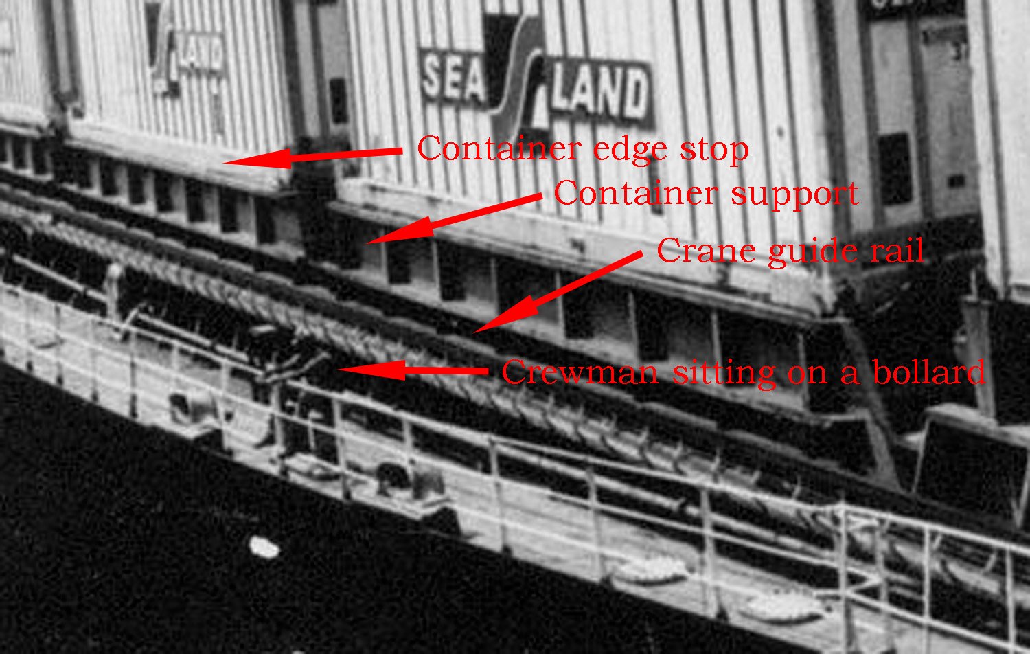
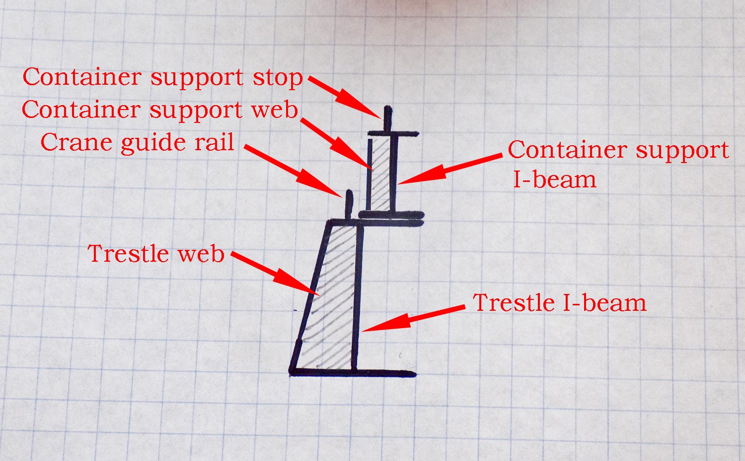
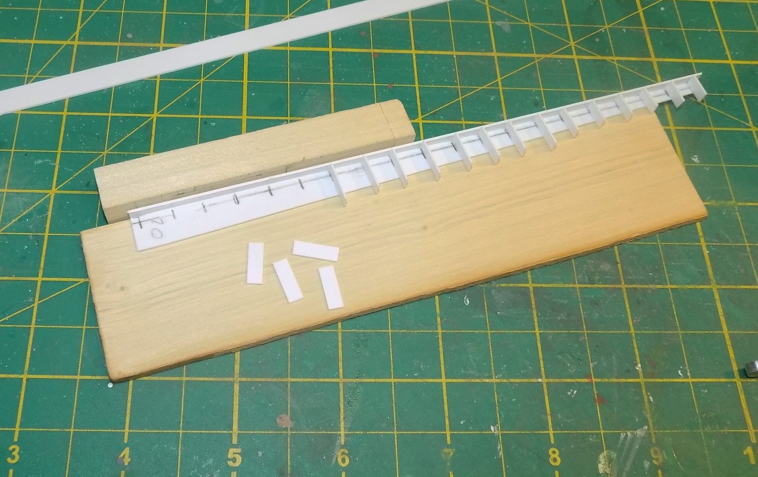
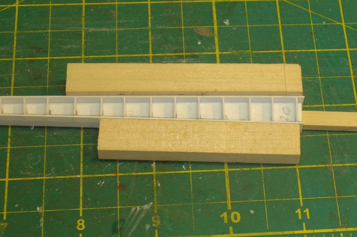
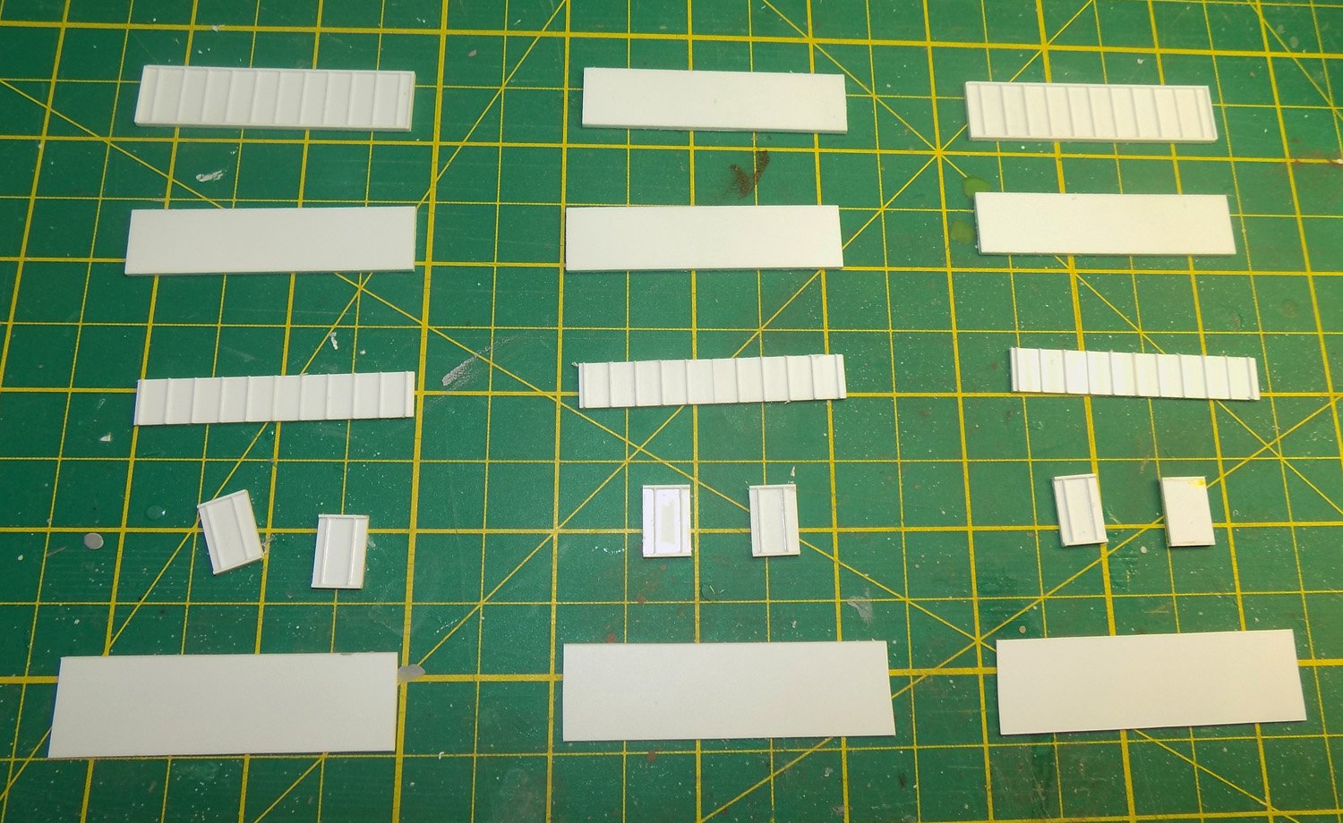
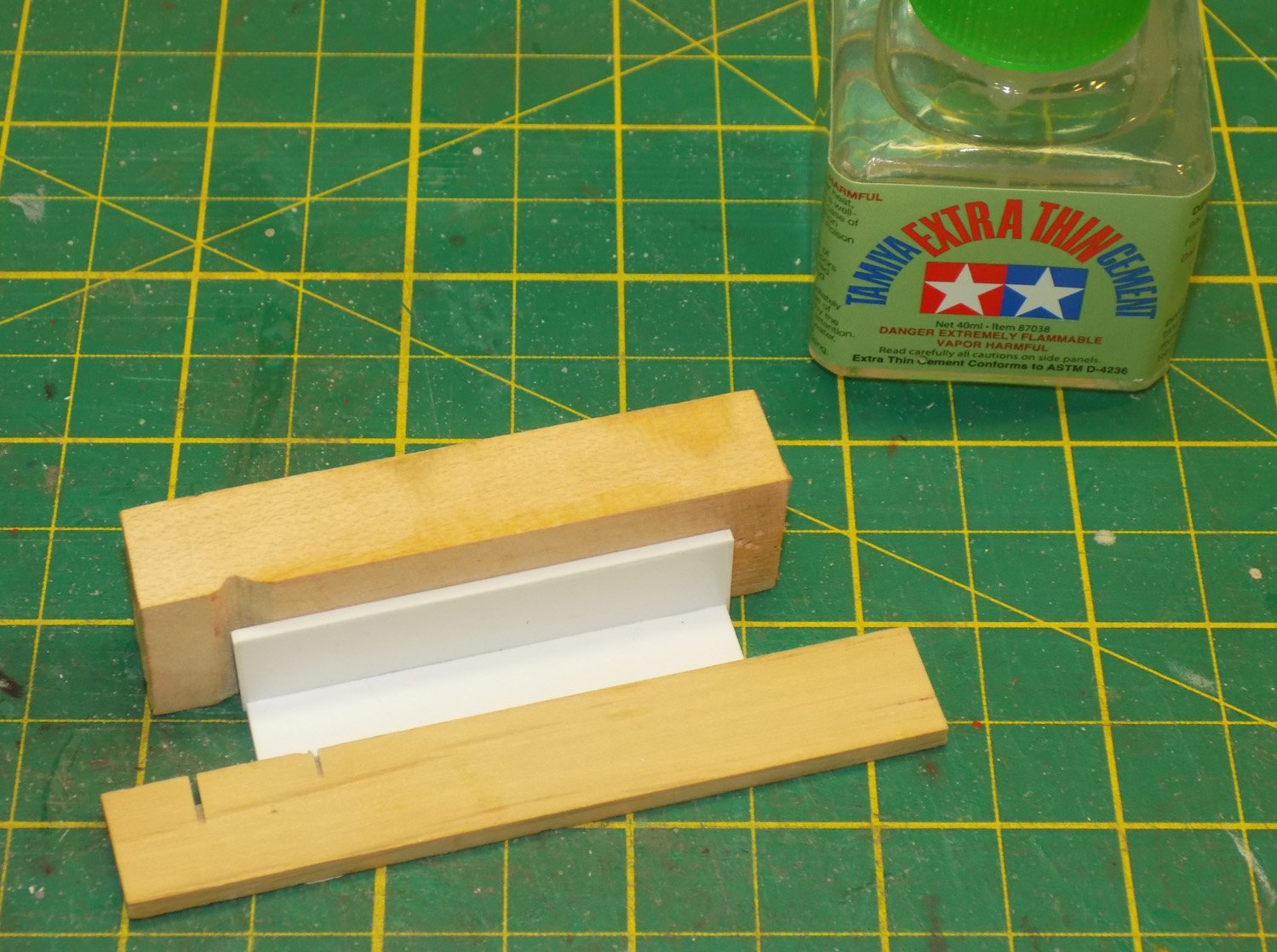
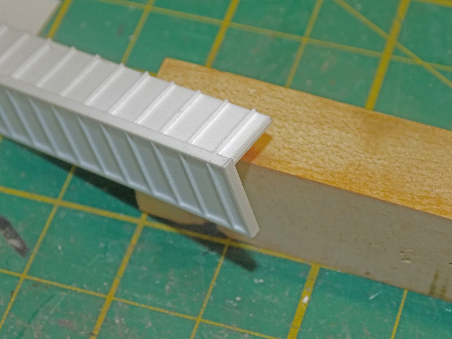
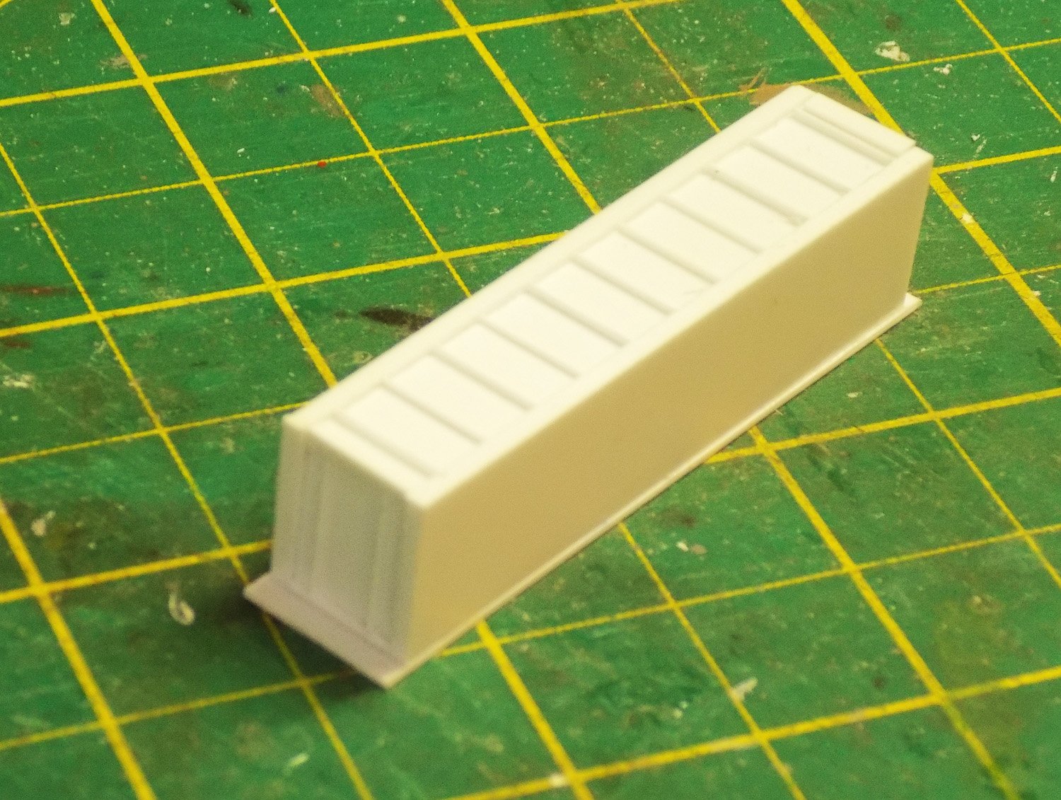
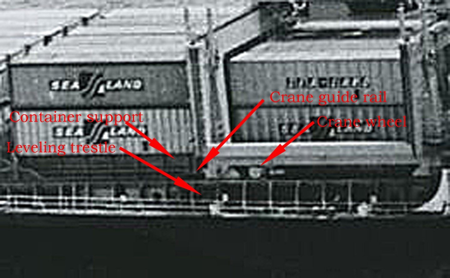
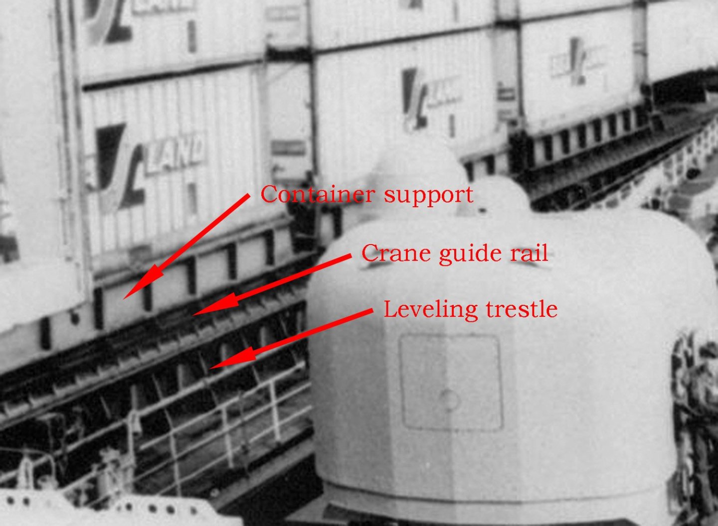
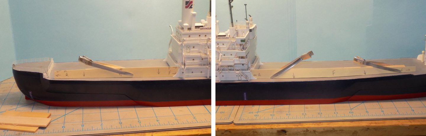
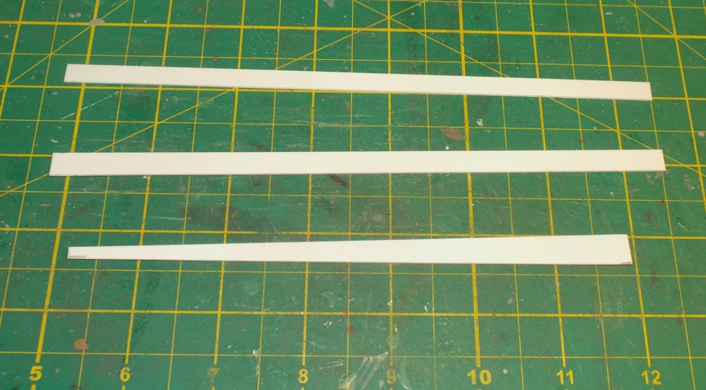
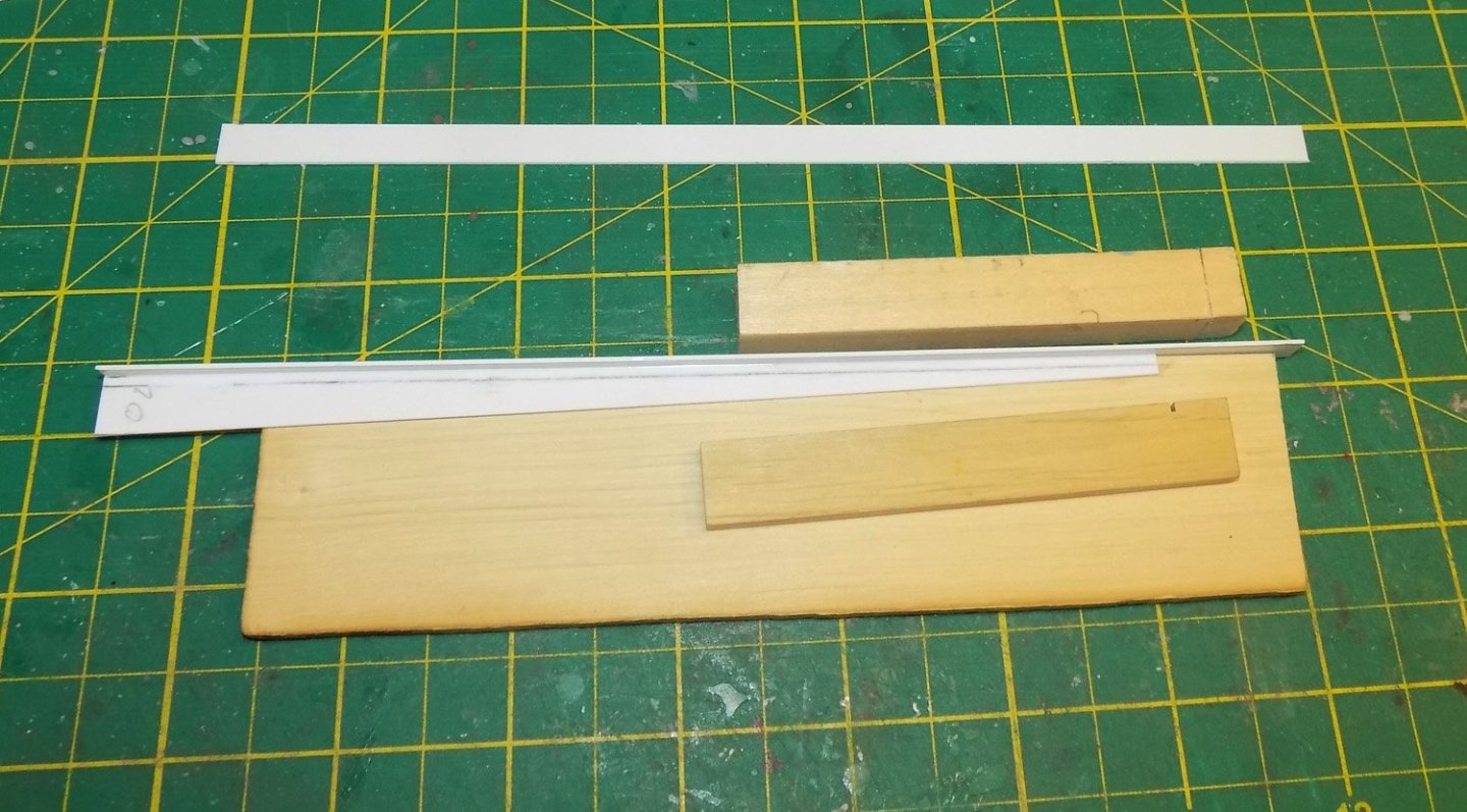
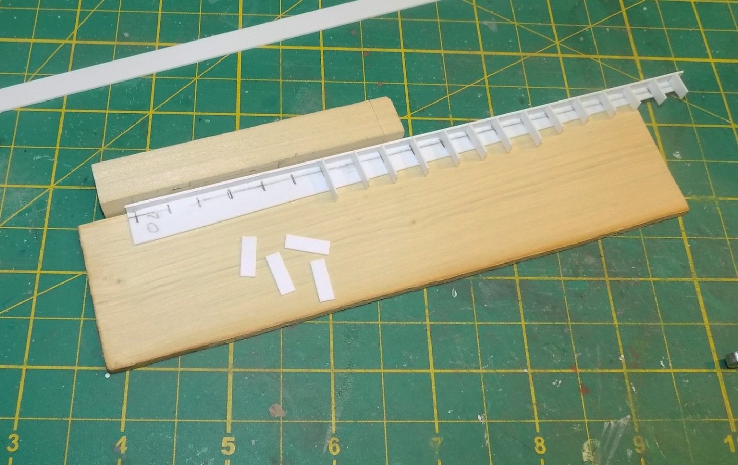
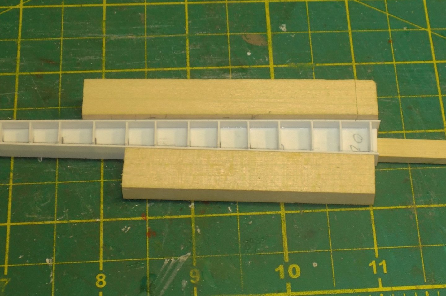
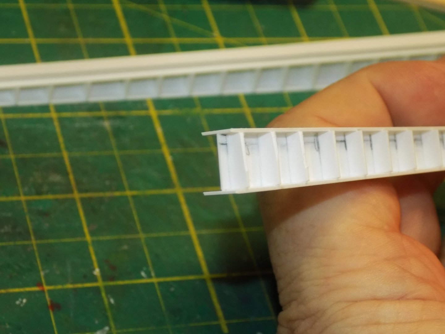
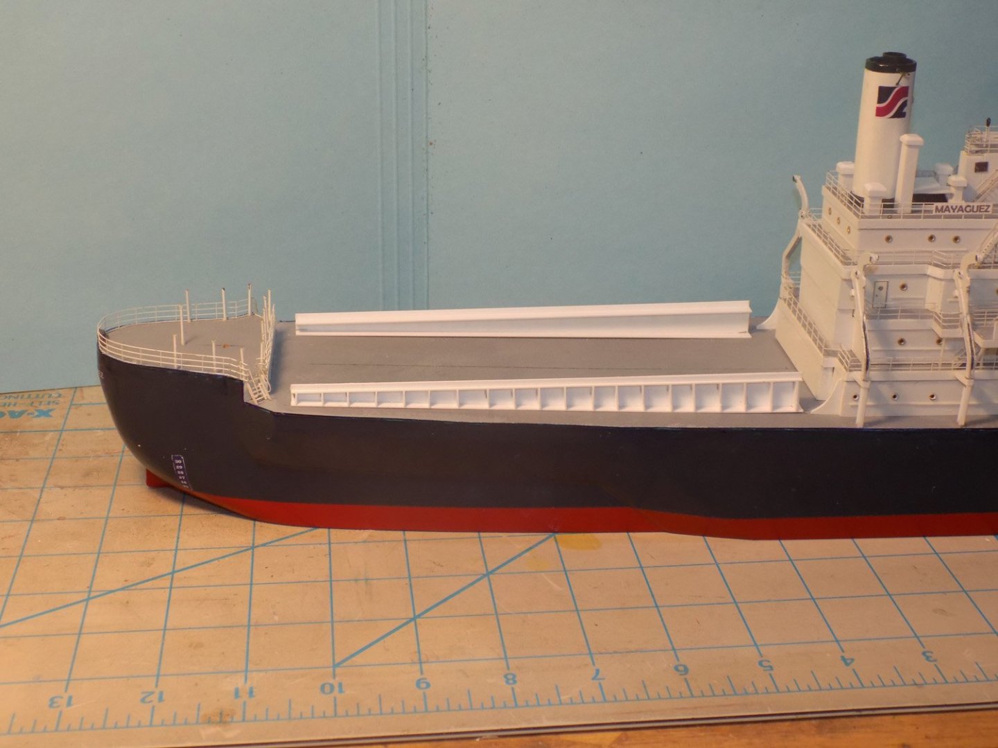
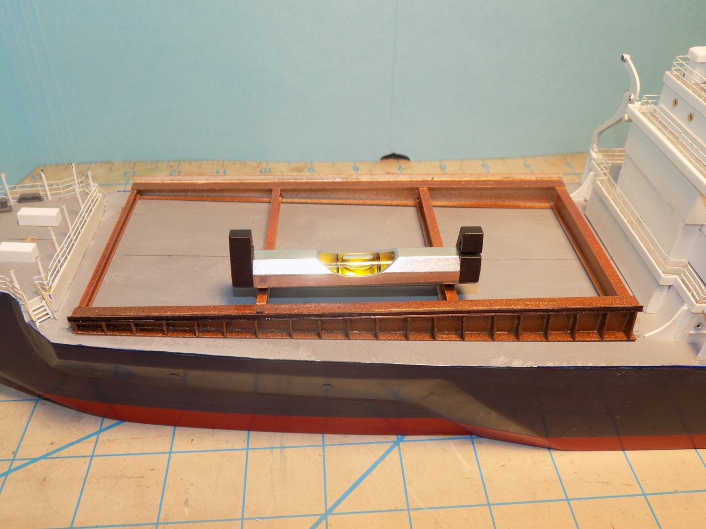
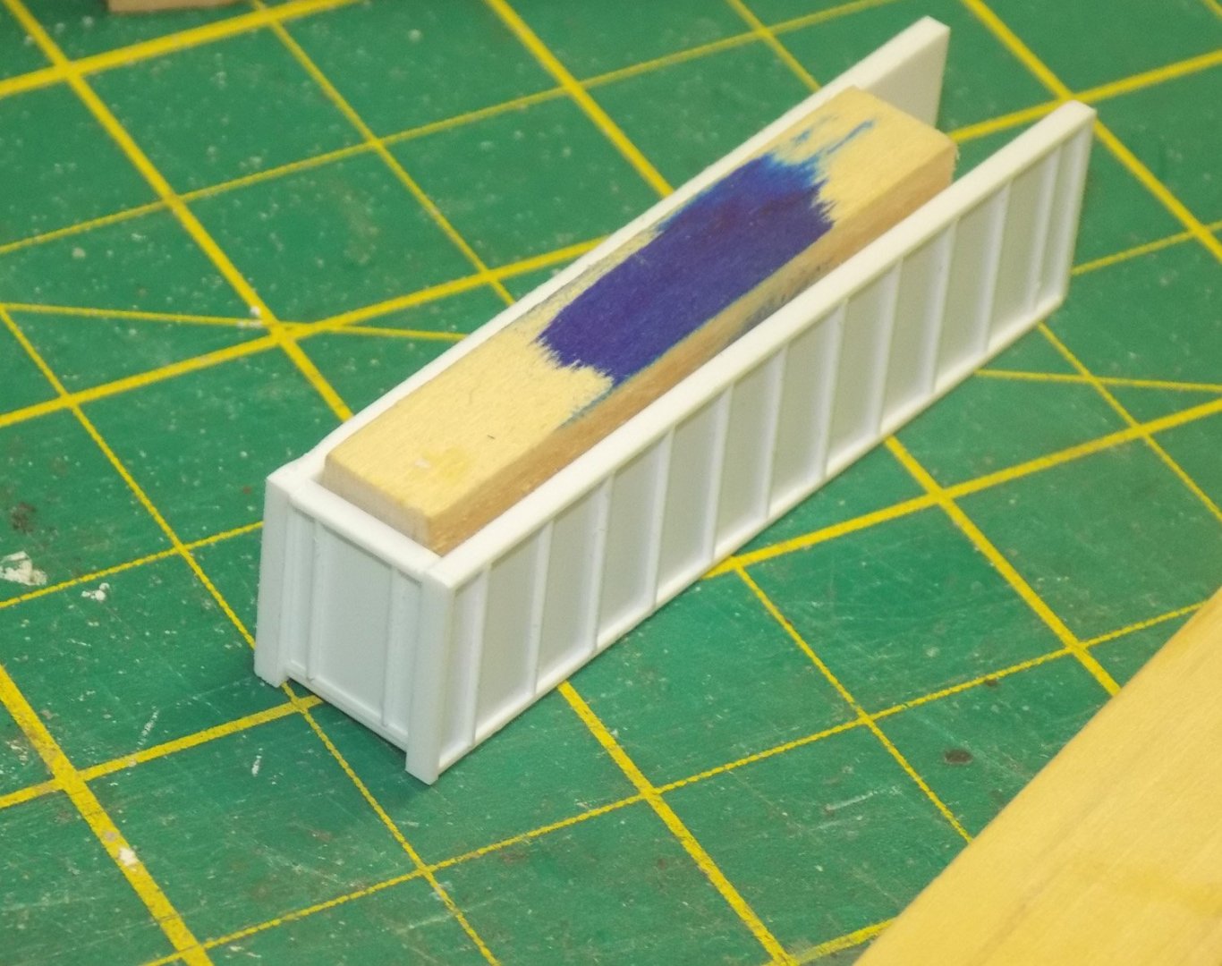
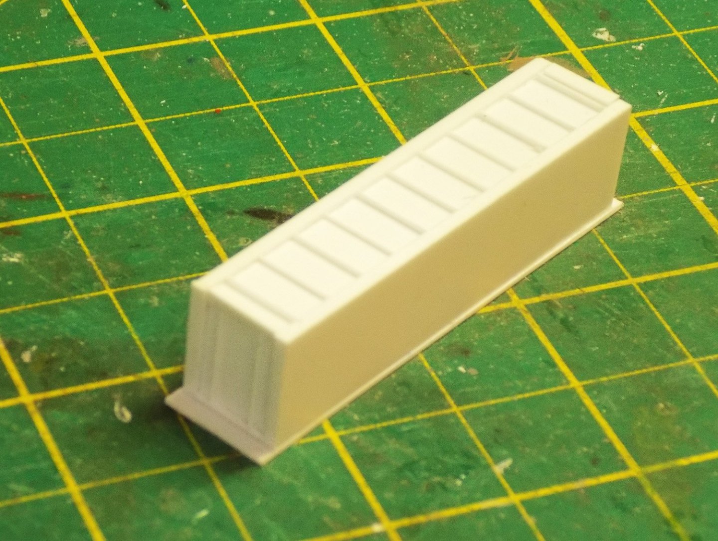
Hi again to all – Thanks as always for the likes and comments. I hope everyone has had a good summer and we are getting back to the workbench and computer, as I am. Thanks also to all who asked about my health problems. They are all getting better, slowly, and in any event were small compared to some of those suffered by other friends in the MSW family. My best wishes for speedy and complete recoveries to all. When I left off last segment the 96 containers had all been built and detailed and set on deck. But they have to be supported on leveling trestles and supports that raise them to a height where the cranes can move them around. As before, there are no plans of these structures, so I had to rely on somewhat fuzzy photos. The interpretations of these were some of the most difficult of the build, and I spent any number of hours staring at the images, changing lighting and contrast, till I had a pretty good idea of how they worked. Here are some of the better images with arrows pointing to the several elements: After all this studying, and keeping in mind what I was capable of building, I came up with this rough cross-section sketch of the various components and how they would sit on or attach to each other: The first element to build was the support trestle. To get the right taper and curve to the vertical piece of the I-beam I clipped pieces of card stock to small wood blocks and set them on the fore and aft decks. With careful measuring and trimming I matched the lower edge to the deck curve. Then using a small line level I laid out and marked the top edge so it was horizontal and parallel with the waterline. The final task was to adjust that horizontal line to a level where the final height of the containers would match the look seen in the photos. Since the container supports had not been built, nor the final structure of the container blocks, this was a bit of an informed guess, but I think it came out OK in the end. With the shape of the vertical piece determined I cut out the tapered piece from 0.03” (.75mm for the metrically minded) styrene. The same plastic gave me a wide bottom piece and a narrower top piece for the trestle I-beam. The tapered piece was laid on a wood sheet of a thickness that supported it at half the height of the lower piece. Using small pieces of wood to hold the plastic pieces against each other they were glued along the joint with thin plastic cement, which essentially softens and welds the pieces to each other. Note that where possible the pieces are cut oversize to be trimmed after gluing. Locations for the trestle web pieces were marked out along the length of the trestle at 3/16” (3 foot in scale) intervals. This may be a bit wide, but it does match the look from the photos. The web pieces were also cut long and extended past the top edge of the vertical piece. Once they were all glued on solidly the tops were cut to match the edge of the piece. Doing it in this sequence meant that I never had to cut and fit the pieces individually to their different lengths. After trimming the web pieces the narrower top piece was glued on using small wood blocks as before. Now the outer edges of the web pieces could be cut to the taper to match the wider lower piece and the narrower top piece. This is the final look of the leveling trestles, which matches the cross-section sketch pretty closely. The crane guide rails were attached to the tops of the leveling trestles and they were set on deck to check their appearance. Plastic I-beams of various heights were attached to the trestles so the port and starboard ones would be parallel with each other. The beams had to be cut to a length that would allow for the thicknesses of the future container supports and the sizes of the containers themselves inside the crane guide rails. A lot of trial and error went into this, and a fair amount of cursing, because the tolerances were so small. However finally a satisfactory dimension was achieved and the I-beams were all cut to this length. After gluing, the trestle assembly was painted dark bronze. I don’t have any references for this choice, but it does set them off from the deck and the containers, and the color is not unknown as a rust resistant coating. A final check with the line level confirmed that everything was up to spec, which was followed by a big sigh and a bigger glass of bourbon. The forward trestles were built in the same manner. Note that there is no beam across the forward end of the forward trestles. The photos show that this area is open, so that is how it was built. The two sets were temporarily laid on deck to see if anything looked wrong or out of scale. Fortunately, I was happy with the results so the pieces were removed and set aside for later use. While this was going on, the final detailing of the superstructure, as well as the bow and stern decks, was also proceeding. These will be covered in the next installment. Until then, stay safe and well. Dan


-
Nils = Just caught up with this build. Nice look to the new deck. With the coamings it looks like it all belongs together. Love the engine. Dan
-
Hi Toni - Those are two excellent anchors. And thanks for showing your casting methods. My own experiments in that area have been less than completely satisfactory. Next time I will turn back to your explanations and try again. As for handling the anchor, since I don't have access to druxey's time machine, I pull out "The Young Sea Officer's Sheet Anchor" by Darcy Lever and see what he says. There is usually a good explanation of the process. Congratulations on the completion, or near completion, of a really sweet ship model. Dan
-
Hi Roger - Two steps forward and one step back has always worked for me. That poop deck is really coming along nicely. Looking forward to seeing it all come together. Be well Dan
-
Hi Toni - Just caught up with this build. Looking extremely nice, neat and clean. Love the capstain. Looking forward to future progress with the rigging. Be well Dan
-
Hi Ken - She looks like she is coming along nicely. I like the developing shape of the hull form. She should look sweet when you get to plank her. Be well Dan
-
Hi Cisco - Just read through your build log here. You are doing great, working your way up the steep and long learning curve of hull planking. I love how you meet and solve the many problems and challenges that you have encountered. Your creative solutions will stand you in good stead as you approach the second layer of planking. Here are a couple of tips that I have learned by hard experience over 35 years of doing this: 1. Fill and sand the first layer of planking till the shape is smooth and to your liking. Paint the whole thing with a light colored water based paint. Now you can draw the plank outlines on the hull in pencil, using dividers or tick strips to give you your initial layout. Look it over critically and change the run of the planks by erasing and redrawing until you are happy. Drop planks at the bow and stealers at the stern are much easier to figure out in pencil before you start cutting wood. Then you can cut and taper your planks to match the pencil lines. 2. Lay in the location of the wale first. This will determine the bulwark planking strakes above and the hull area to be planked below. Plank down from the wale and up from the garboard, as you did before. The final opening will be closed with a 'shutter plank'. When you get to that point, lay on a piece, or pieces, of translucent tape covering the opening. Draw the outline of the shutter plank on the tape, then transfer the tape to a wider piece of planking material and cut to the line. This should quickly get you very close to the final shape that you need. 3. For the garboard, lay the lower edge of the wider planking material (1.5 times the width of the hull planks) against the keel rabbet and slide it forward until the front end begins to lift as the rabbet curves up the stem. Pull it back just to that point and temporarily tape it in place. This has been suggested before. But now take a second plank (known as the first broad strake), place it on the hull above the garboard piece, and slide it forward until its lower forward corner contacts the stem rabbet. Mark this point. This is how high the garboard should come on the stem. Cut the bow end of the garboard strake to fit the open curved triangle that has been marked out. Now the lower edge of the broad strake will be straight, and you can work off it up the stem. I hope that helps a bit. Feel free to ignore it if not. Best of success. Dan
-
Hi Mark - Glad you got the warping problem under control. Looking forward to seeing the solution. Have you considered buying small photoetched cleats? I know they are out there, but can't remember who makes them. If they are painted brown, at that size I don't think anyone will be able to tell that they are not wood. Just a thought. Dan
- 505 replies
-
- 5
-

-
- vanguard models
- Sphinx
- (and 1 more)
-
Hi Mark - Just read through the log. You are making excellent progress and the results are inspiring. Now I'm off to read the Sphinx log. Thanks for giving me some happy hours of reading. Dan
-
Impressive research, Marc. Your thoughts are fascinating and your conclusions fully supported. I always look forward to your next post. If you ever collect and collate them into a book I will be one of the first on the purchase list. Thanks for sharing. Dan
- 2,699 replies
-
- 8
-
-

-
- heller
- soleil royal
- (and 9 more)
-
Chris - Just went through this build log and am truly impressed. It is amazing how clean and crisp all your edges are and how you persevere in building all those tiny details. PS - my vote is to spend for the 3-D printed hedgehogs and other fittings. Sometimes it is better to beg forgiveness than to ask permission. Flowers and a dinner at a good restaurant always eases those difficult conversations with my wife. Be well Dan
-
Just beautiful brass work, Keith. I am always envious of your work. Can you set up a link directly to this build log in your signature, the way you did for Altair? My system is a bit clunky and I have to go to your profile before I can access this log. Love following along, as always. Dan
-
Marc - I think that you have perfectly illustrated the many puzzles that we all have to solve to achieve a fully realized ship model. In your case you are even more limited by the basic structure of the kit. There is only so much kit-bashing that can be done, and you are doing it extremely well. I was worried that you would not be able to justify the various levels, heights, and angles of the headrails, but your solutions are elegant and beautiful. Looking forward to seeing more great work. Be well Dan
- 2,699 replies
-
- 9
-
-
-
- heller
- soleil royal
- (and 9 more)
-
Thank you Jim, Druxey - Yes, I did consider casting, but my previous forays into those mysteries were less than perfect, and I did not think that these shapes, with the many undercuts, would lend themselves easily to the process. Dan
-
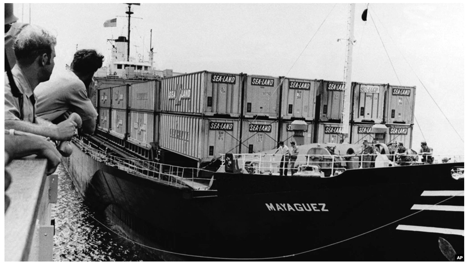
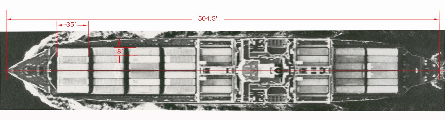
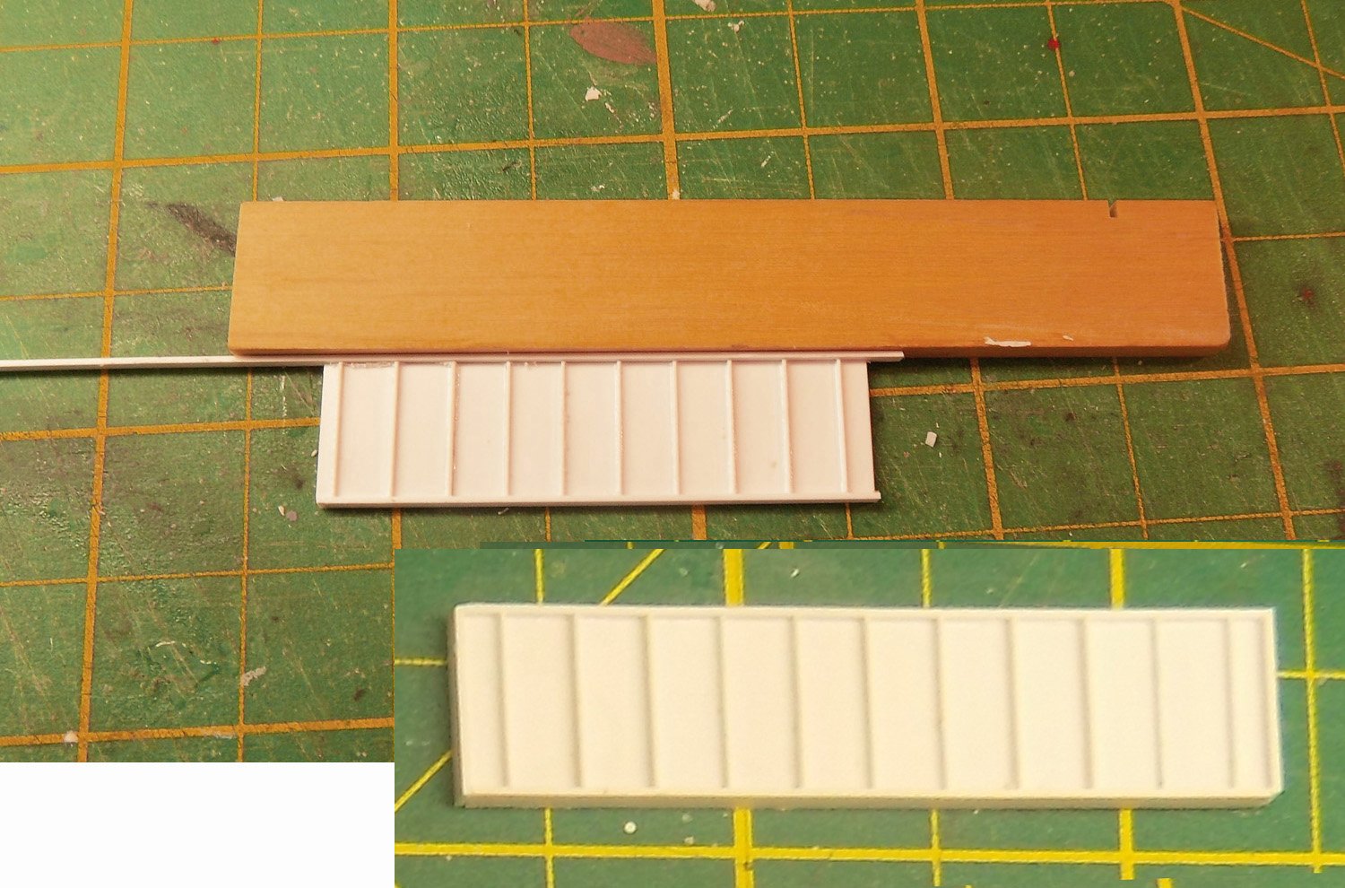
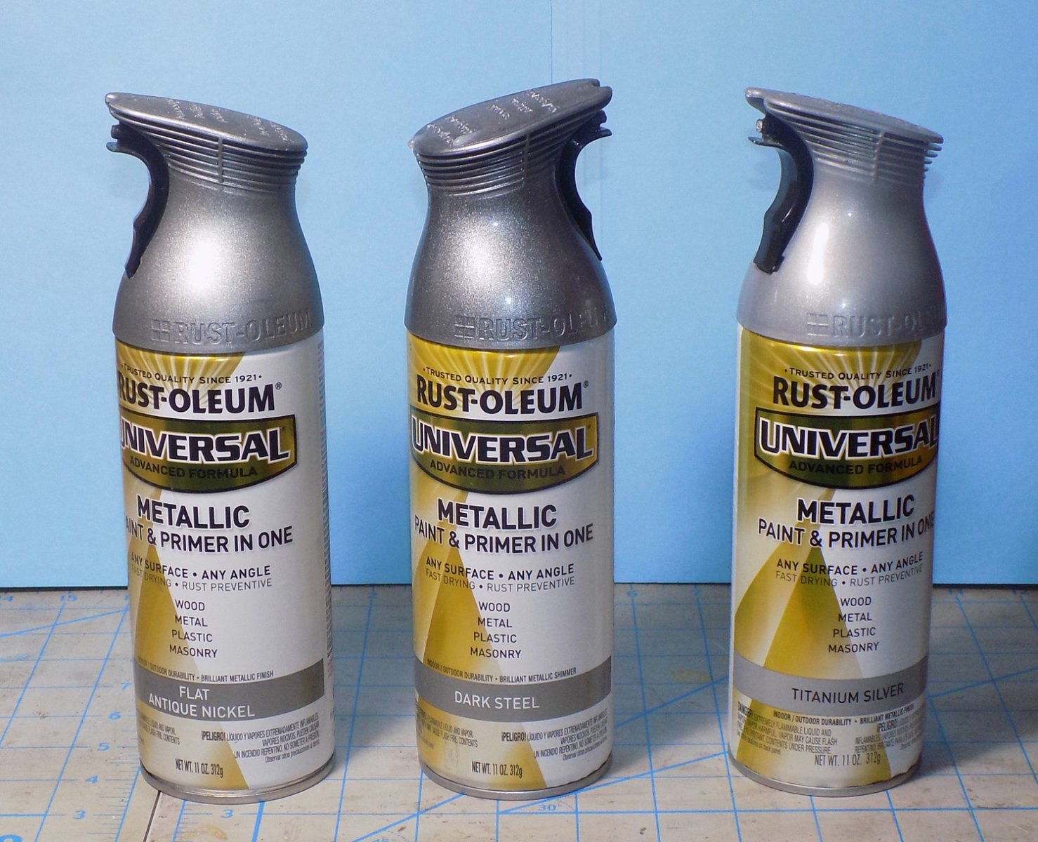
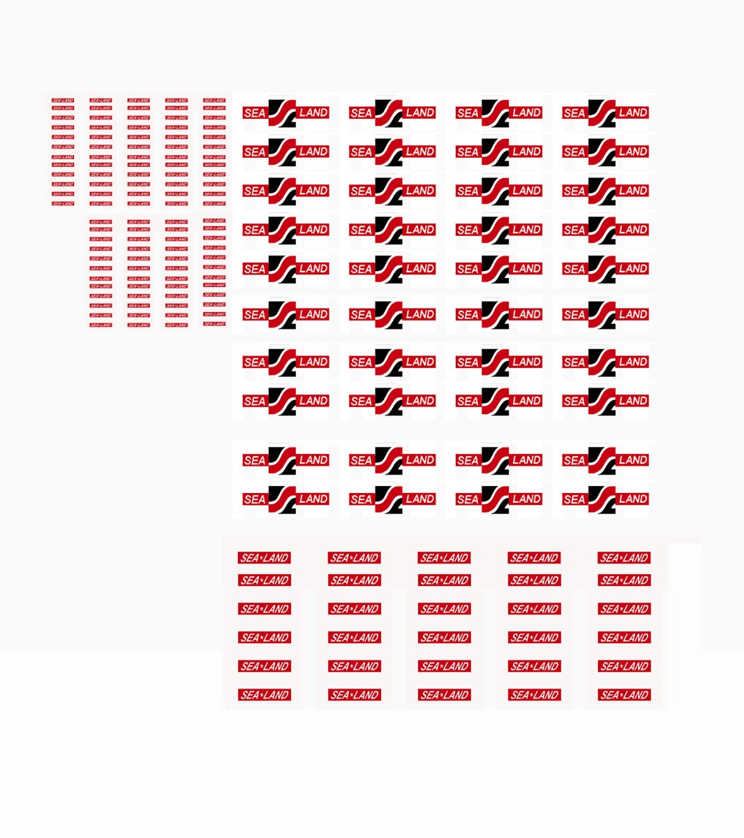
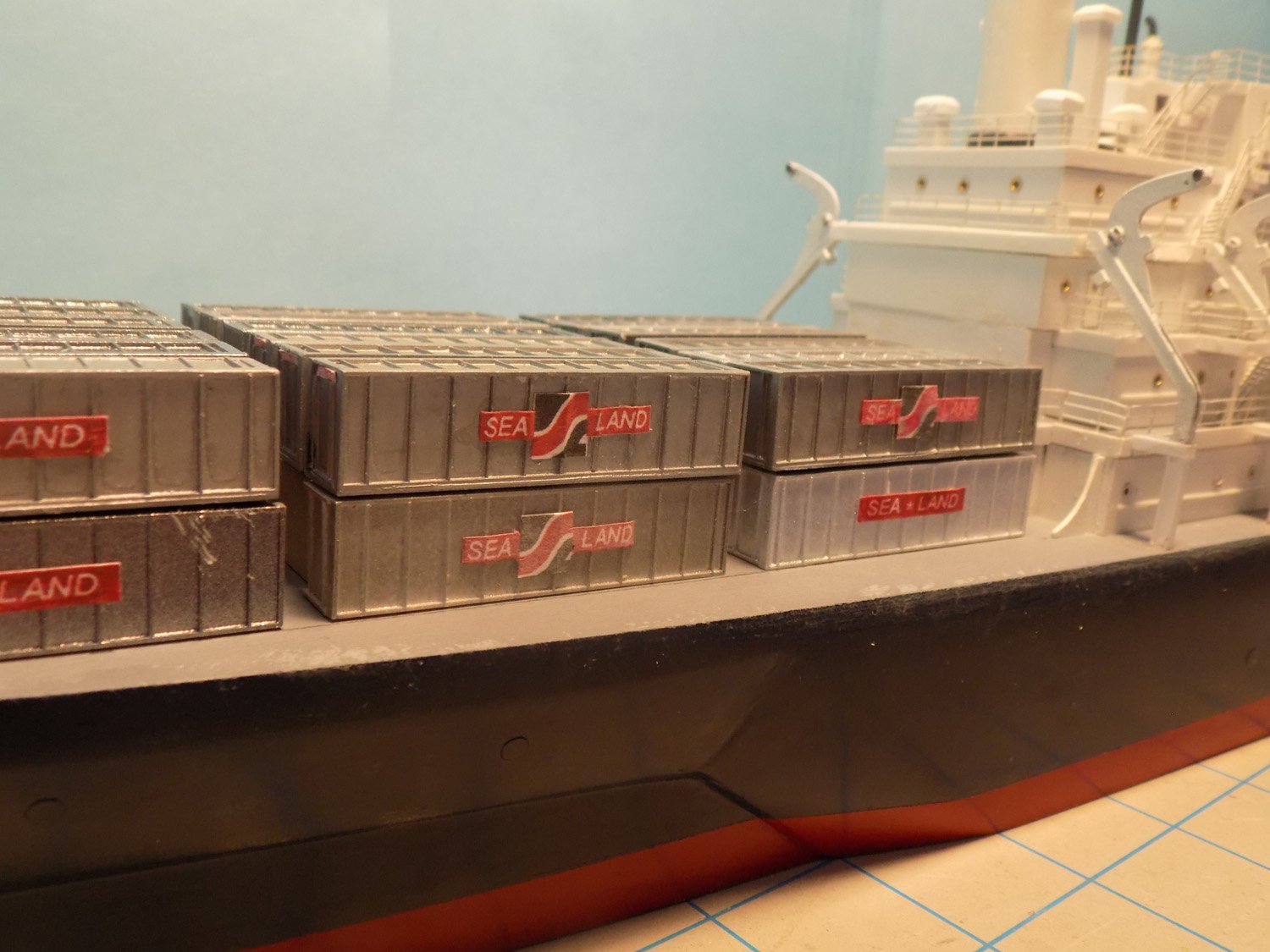
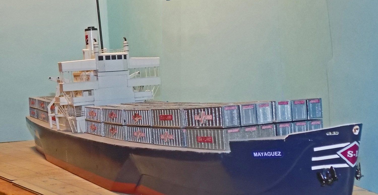
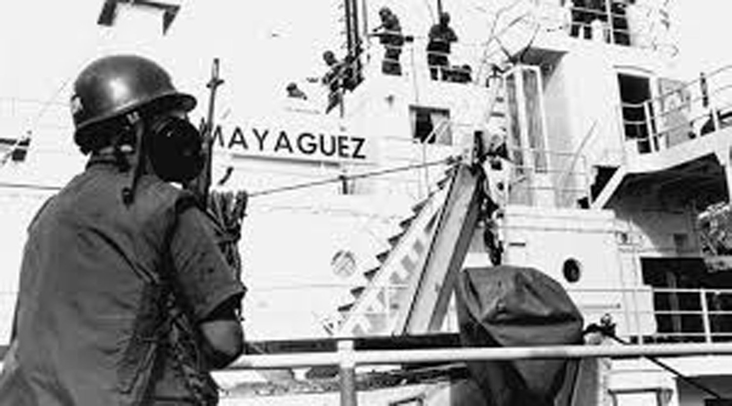
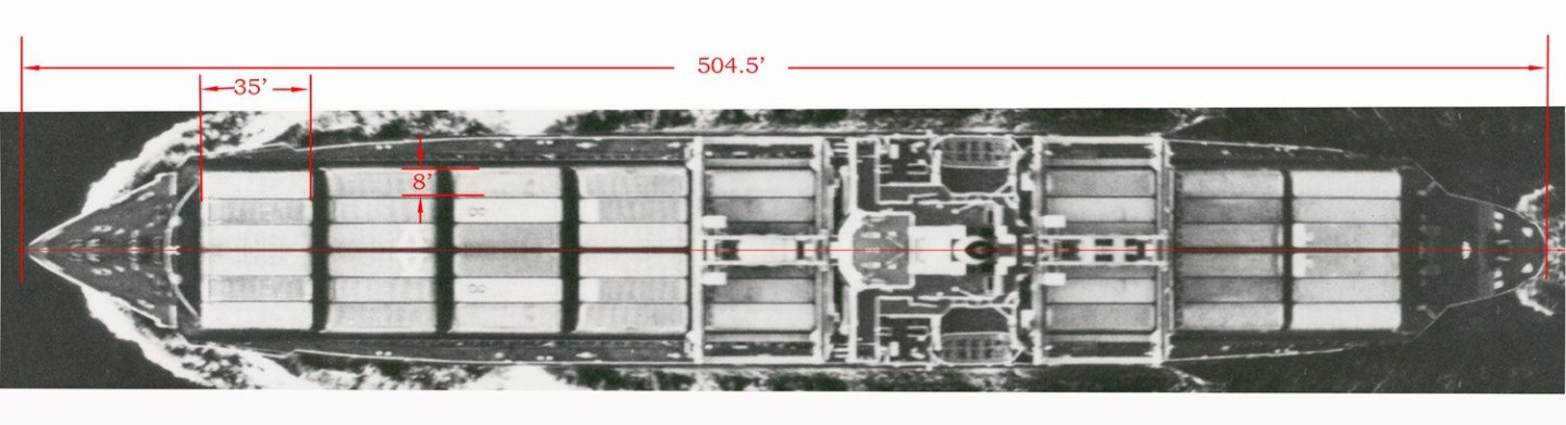
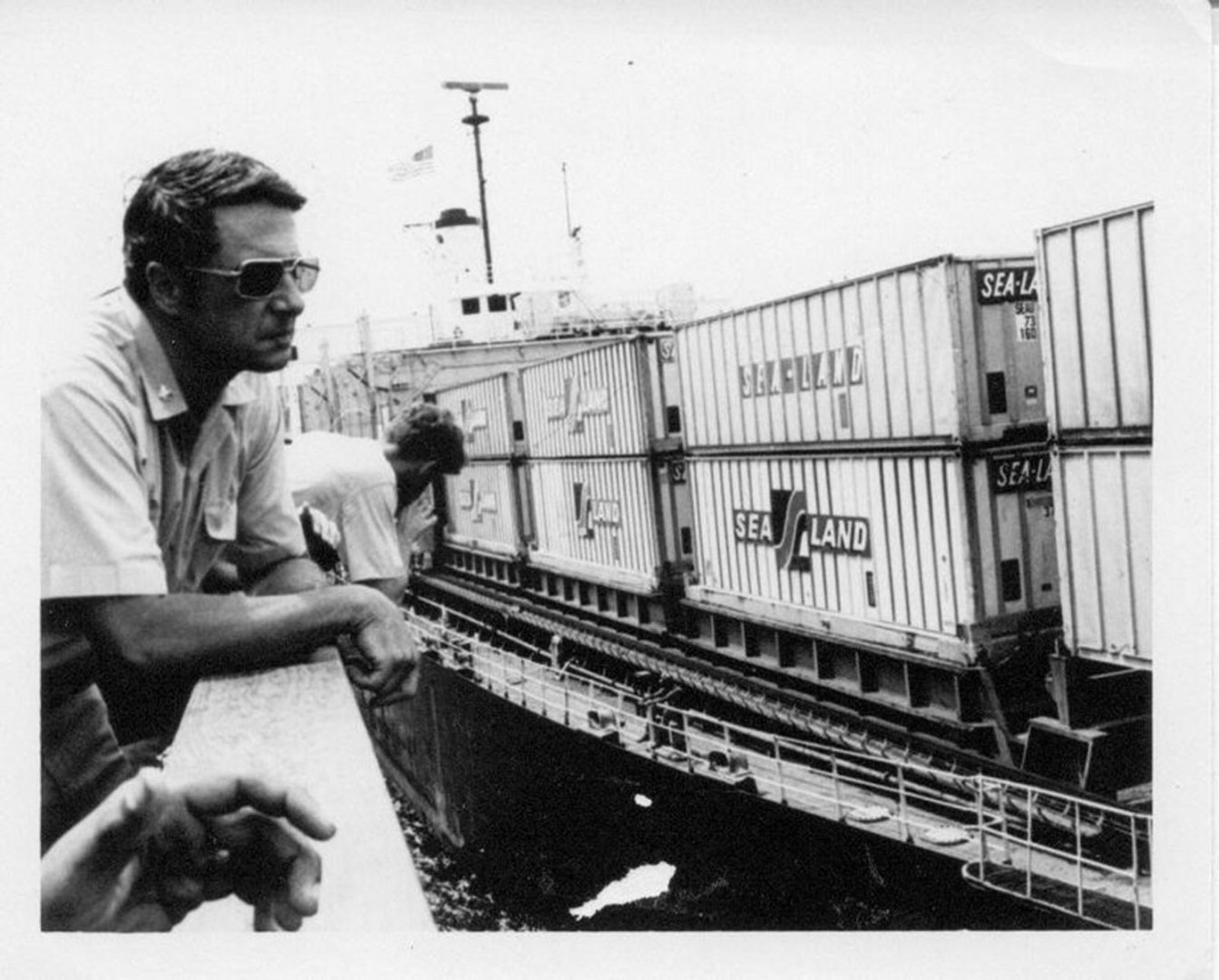
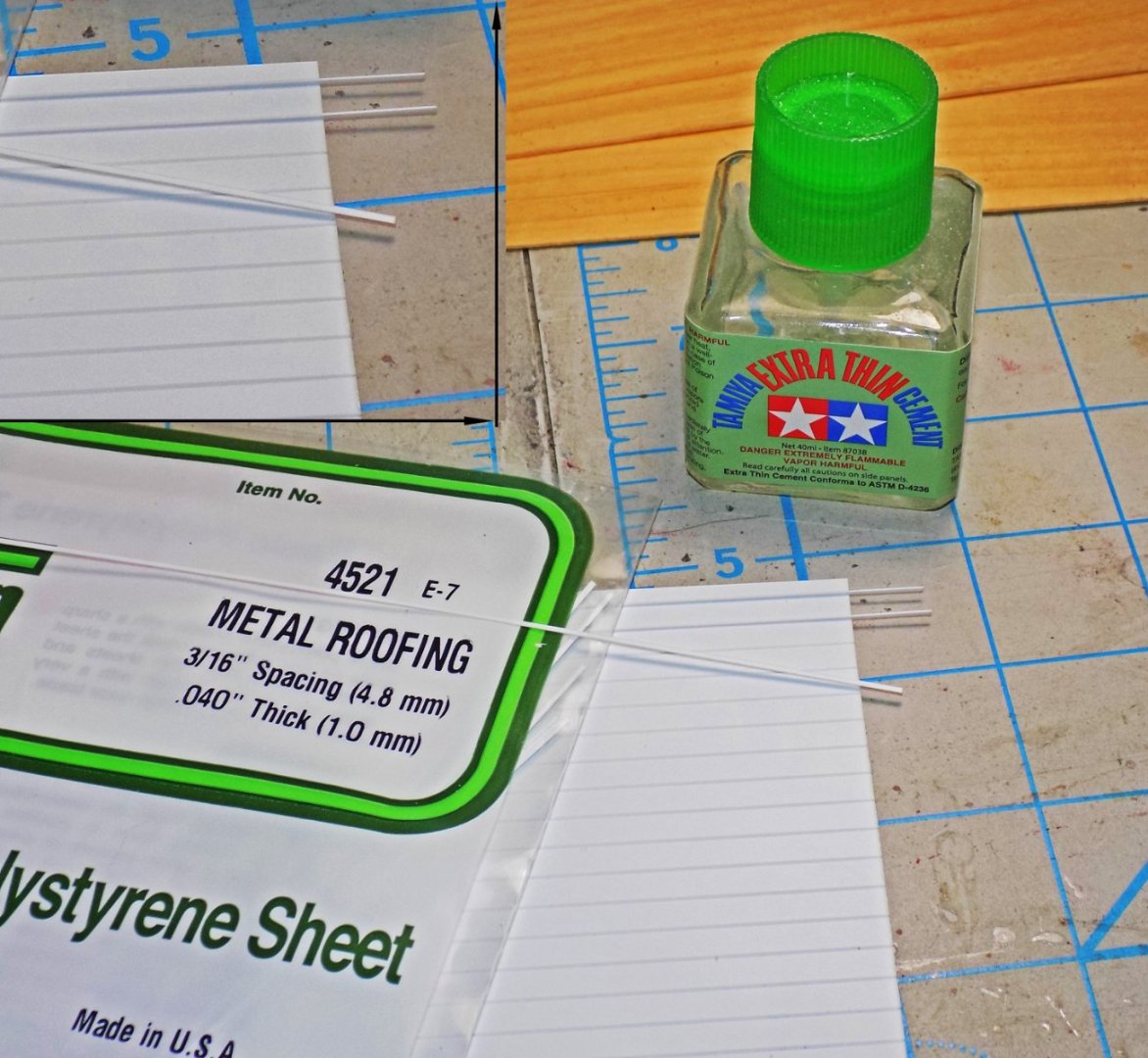
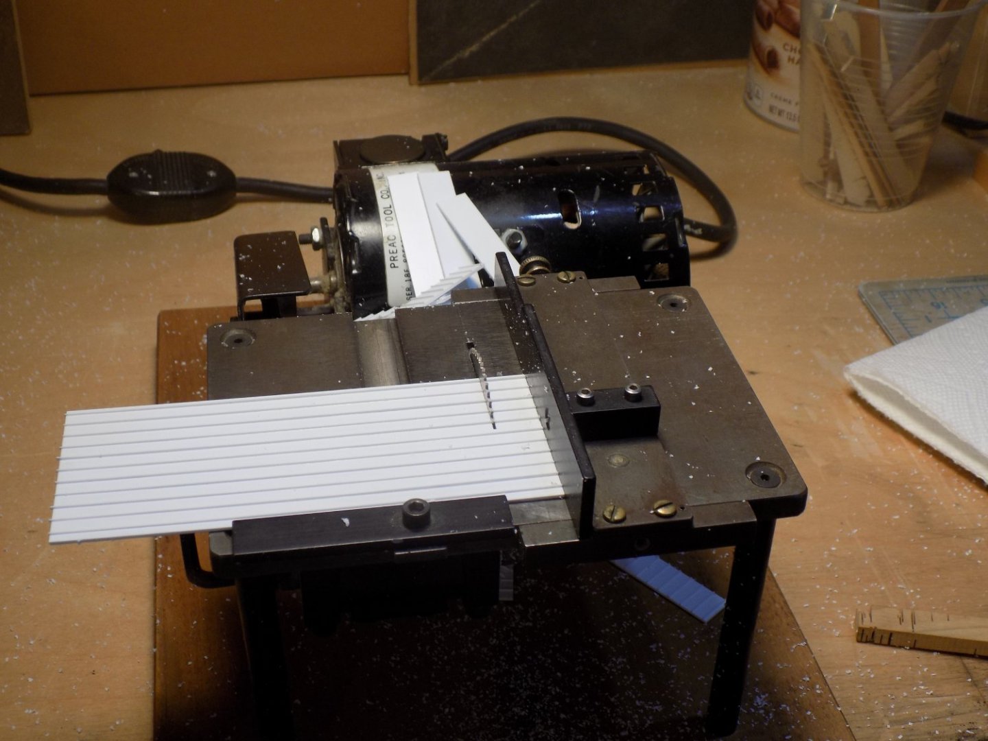
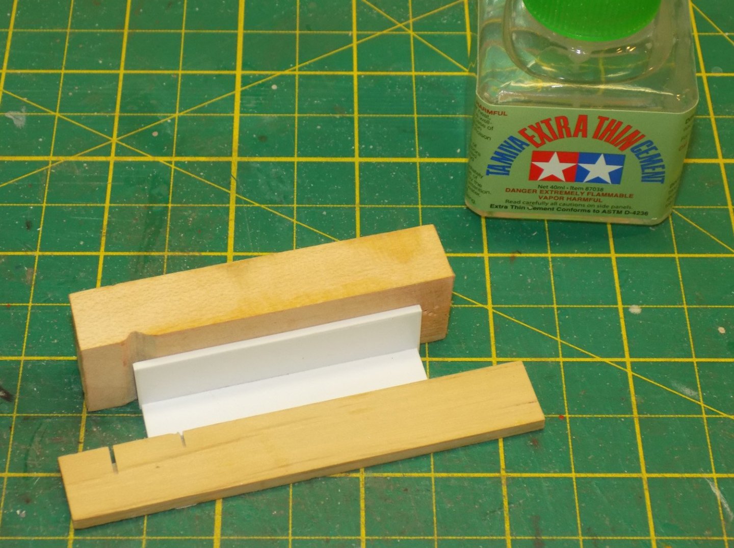
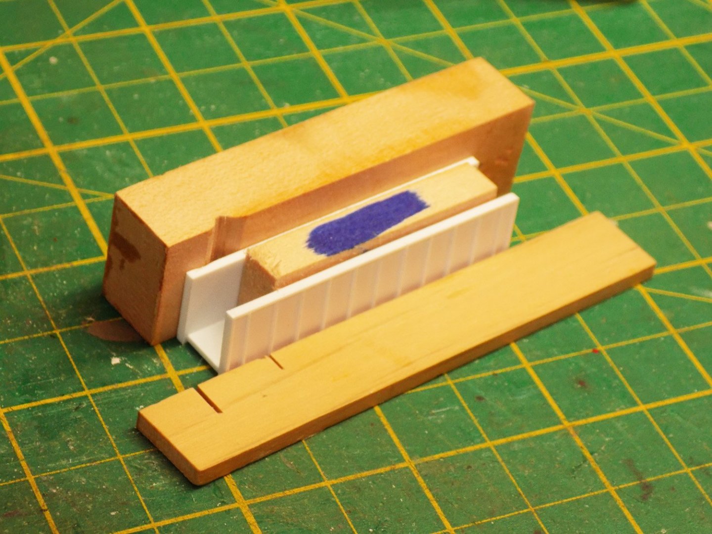
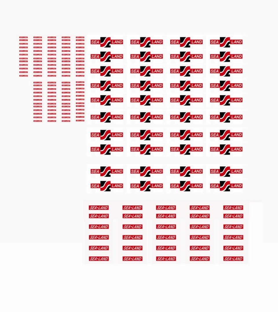
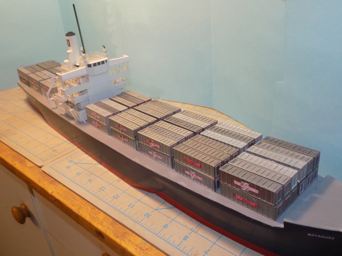
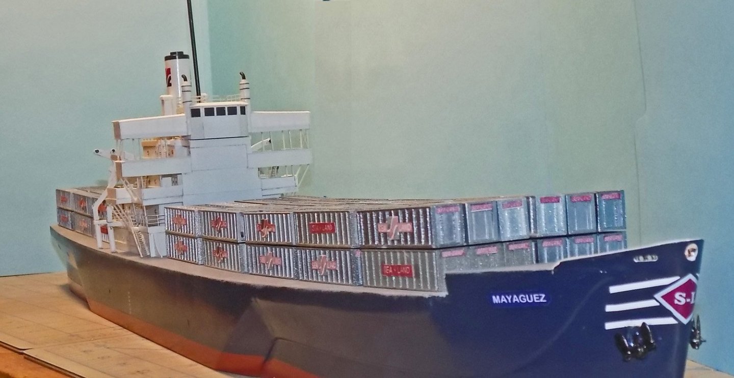
Hello again – Thank you all for your well wishes on my health. I do seem to be recovering, slowly, on the long covid front. I can mostly sleep at night without coughing or sitting up, but it does come back with a vengeance from time to time. The silver lining to this cloud is that I can get more done during the insomniac periods. Hence, this post somewhat quickly after the last one. As in most builds, especially with modern ships, I work on several sub-projects at the same time. While the superstructure was still being finished I turned to the containers on deck. In an earlier build of a container ship model for the museum, the El Faro (build log soon to be written), I had researched these ‘intermodal containers’. I found that ninety percent of the global container fleet are closed rectangular boxes, almost all 8 feet (2.44 m) wide, and of either 20 or 40 feet (6.10 or 12.19 m) standard length, and with a standard height of 8 feet 6 inches (2.59m) as defined by the International Organization for Standardization (ISO) regulation 668:2020. The height and width of the containers on the Mayaguez seem to fit these dimensions in this photograph taken just after the recapture of the ship. You can also see that they are stacked in sets of three, and in two layers. However, to my surprise, when I used Photoshop rulers and scaled out the length of the containers from the overhead shots, they measured out to only 35 feet long, a size that I had not encountered before. Back to the books! After a good deal of reading I located a single sentence in “An Act of Piracy, The Seizure of the American-flag Merchant Ship Mayaguez in 1975” by Gerald Reminick. There he says that when Grace Line sold its Santa Eliana, ex-White Falcon, to Sea-Land Service in 1965 the ship was sent for a second conversion where the container cells on board were enlarged to accommodate the new 35 ft. containers. It was Sea-Land that changed her name to Mayaguez later that year. Now that I had confirmation of the correct sizes, I had to determine the details of their structures. Modern containers have sides of pressed metal with the corrugations quite close together, like those in a cardboard box. Instead, the 1965 containers had smooth sides reinforced with square section battens spaced much further apart. In the detailed photographs of the Mayaguez containers only 16 of these battens can be counted. With the two ends there are 17 panels, so in 35 feet the battens must be close to 2 feet apart. I tried a number of ways to create this look. I started with looking around for what was commercially available, but none of the Evergreen Plastics sheets were close. Neither their railroad car, passenger car or siding extrusions were close to what I needed. Then I tried making them myself, gluing 0.01” square strips to smooth plastic sheets at a spacing of 1/8”, but I could never keep the long strips straight. If I did it by eye, they wandered all over before the glue dried. If I held them against a metal or wood straightedge, then they got glued to the straightedge. This happened even when I used thin glue meant just for plastic, which melted the plastic, but the melted plastic then would attach again to the straightedge. I tried cutting narrow parallel channels with a thin blade in the Preac table saw, to be filled with thin strips, but the depths could not be cut consistently. Ultimately I decided to compromise on the look a little in order to get it done. Evergreen has a product which represents a metal roof with batten supports (#4521). It comes as a sheet 0.04” thick with channels 0.015” deep set 3/16” apart. These channels are to be filled with thin strips 0.01” x 0.03” which are supplied with the sheet. Doing this is a tedious process, to say the least. Each strip had to be turned on edge and set into the start of the channel. It was tacked there with a small drop of Tamiya extra thin plastic glue (which is mostly acetone), which welds the strip to the sheet. Then the rest of the strip, still set upright, had to be fed into the length of the channel and glued there. There was a distinct learning curve and a good bit of wastage of these expensive sheets before I got the hang of it. The final product looked very much like the photos of the container sides, although the spacing of the battens was 3’ rather than 2’ apart. As mentioned before – GEFGW. With the strips in place the six pieces for each rectangular box had to be designed and cut. Each had to be sized to compensate for the thickness of the material so that the final assembled size was 0.50” x 0.53” x 2.19” (8’ x 8.5’ x 35’). I also had to compensate for the various edging strips that were added to make up the look of the corners of the boxes. Once all the calculations were done, the pieces for the sides were parted off the sheet on the Preac. These ribbed side pieces then had to have edging around all four sides, made from strips 0.02” x 0.06”. The final piece is shown in the insert below. The final components are shown below. These are the ones needed for a set of three containers. To minimize the number of ribbed pieces only the outside sides, ends and tops of the containers are ribbed. Where the side will not be seen it is not ribbed. The first step to assemble each container was to set a side piece against a top piece using wood blocks to hold them perpendicular. Thin plastic glue was fed along the seam and held until it was hard. Turning it over the matching ribs can be seen. The second side is attached in a similar manner, but using a specially cut wood spacer to keep the sides parallel. I marked it in blue so I would not throw it out by mistake. Each end was installed using the spacer block again to make sure it was vertical. Finally the open box was turned over and laid on the base, which had been cut a bit oversize. When the glue was dry the excess was trimmed and the container complete. To give some differentiation and interest to the containers they were randomly painted in three different metallic colors: dark steel, flat antique nickel, and titanium silver. Placards with the Sea-Land logo and name were created in my computer and printed out onto thin acid-free paper. Two different styles for the larger side labels and small ones for the ends as seen in the photographs. With the labels attached the containers were attached in sets of three to an underlying base plate and stacked on deck to judge how well they fit. Here they all are, 8 stacks of 12 containers each. Sitting here you can see the curve of the sheer of the deck. Without some levelling structures the cranes would not have been able to move them consistently. Those structures will be covered in the next installment. Thank you all for following along and for your interest and comments. Be well Dan


-
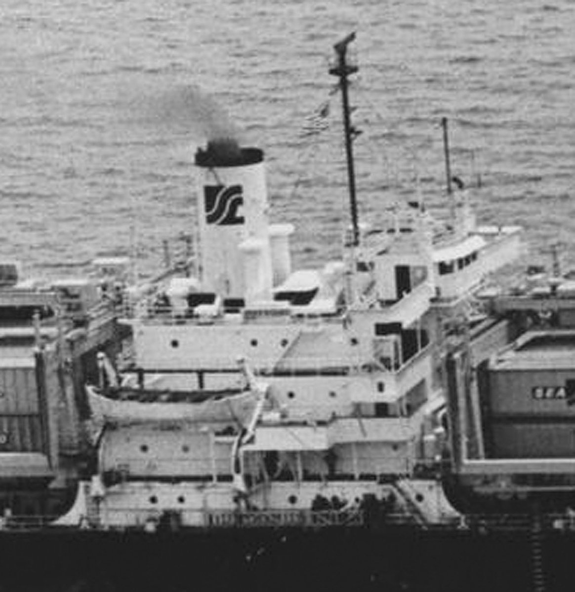
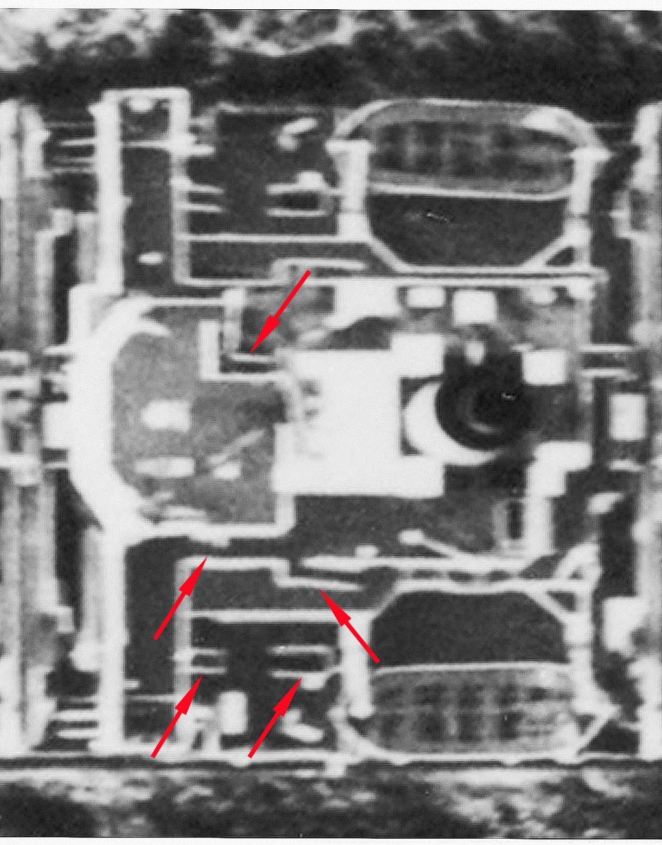
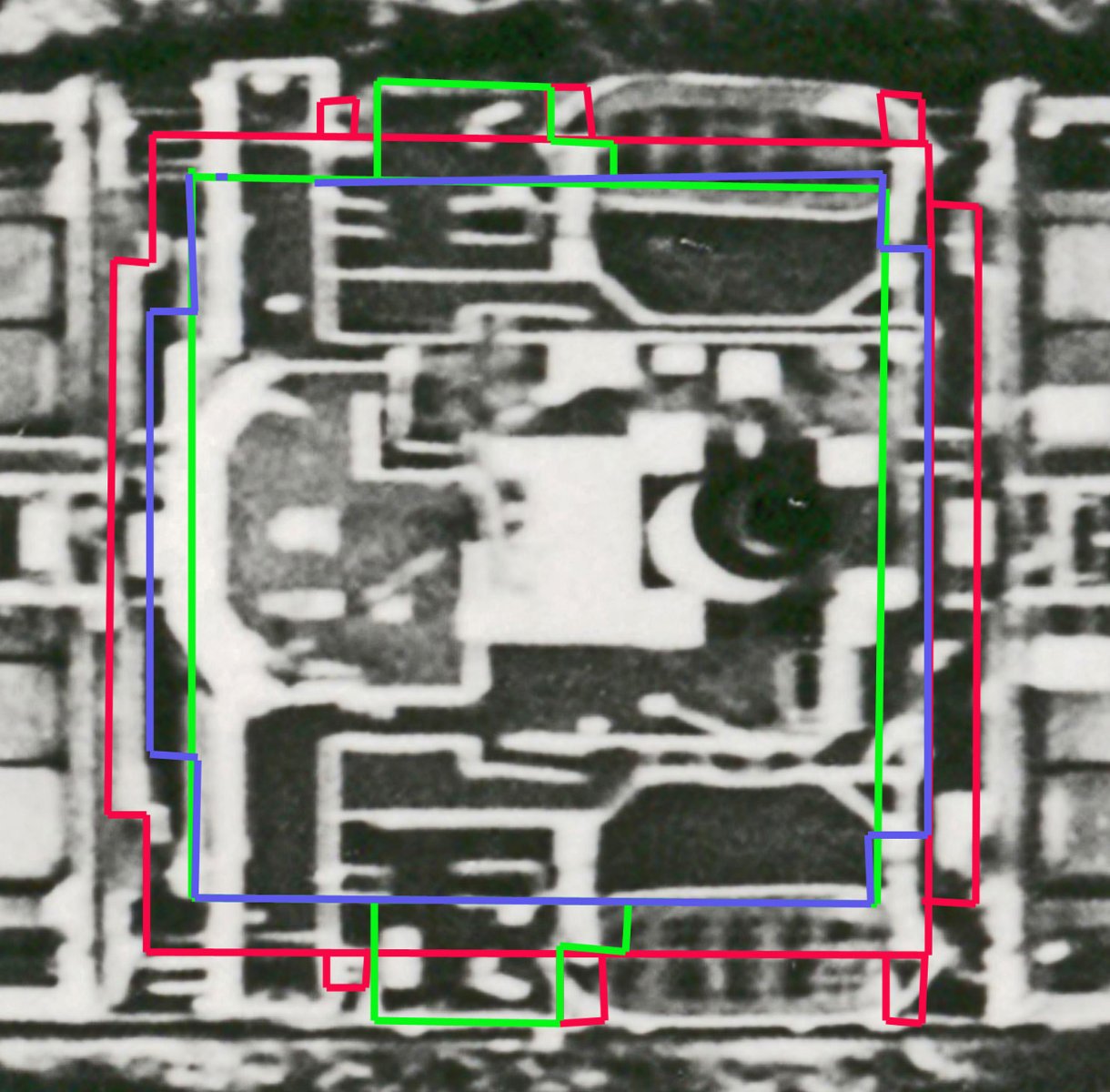
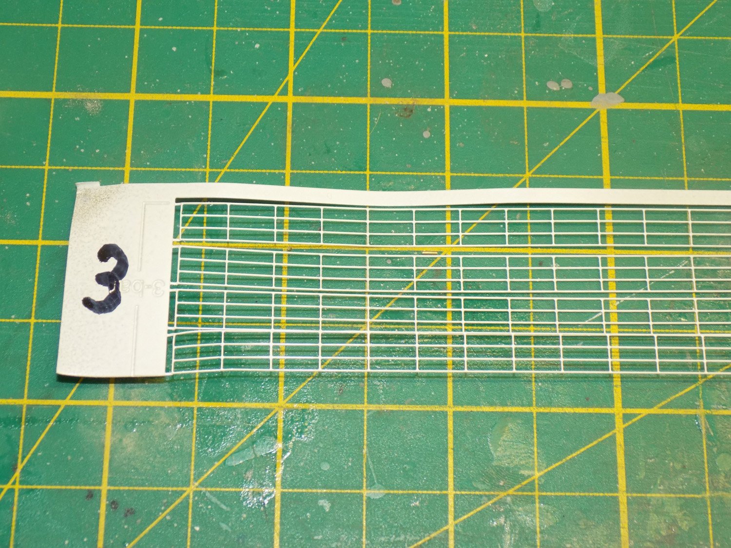
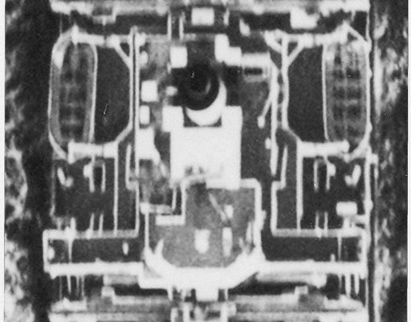
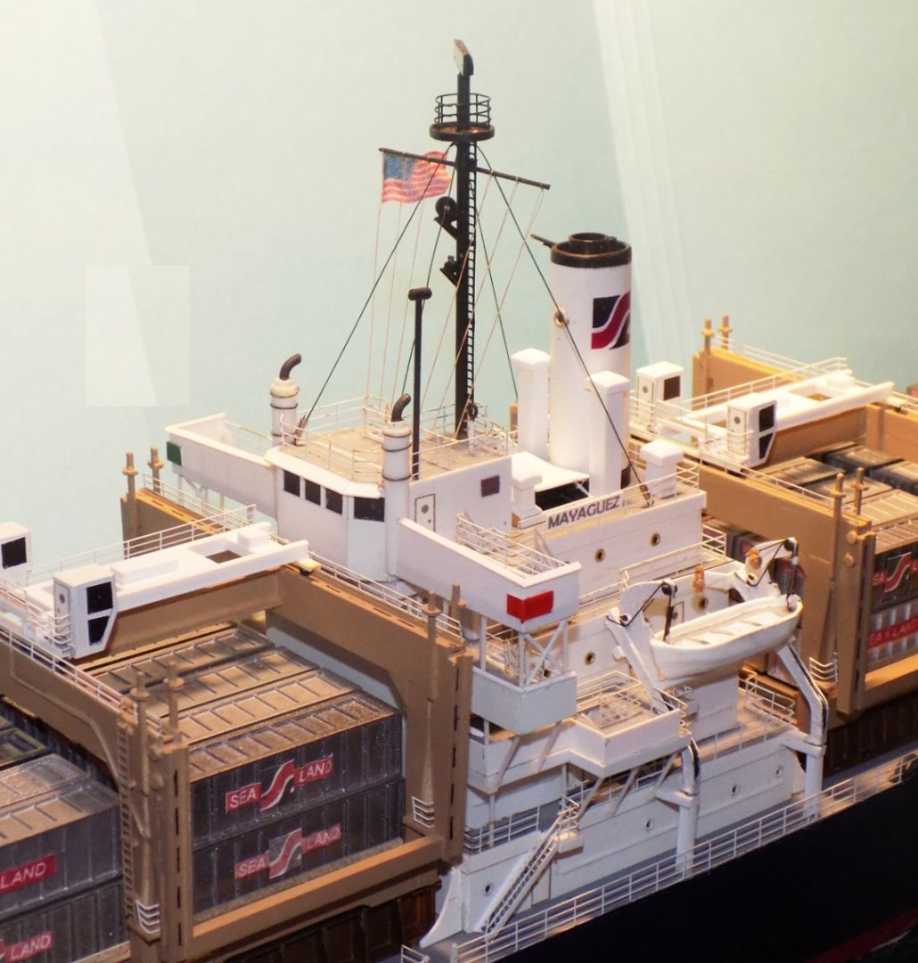
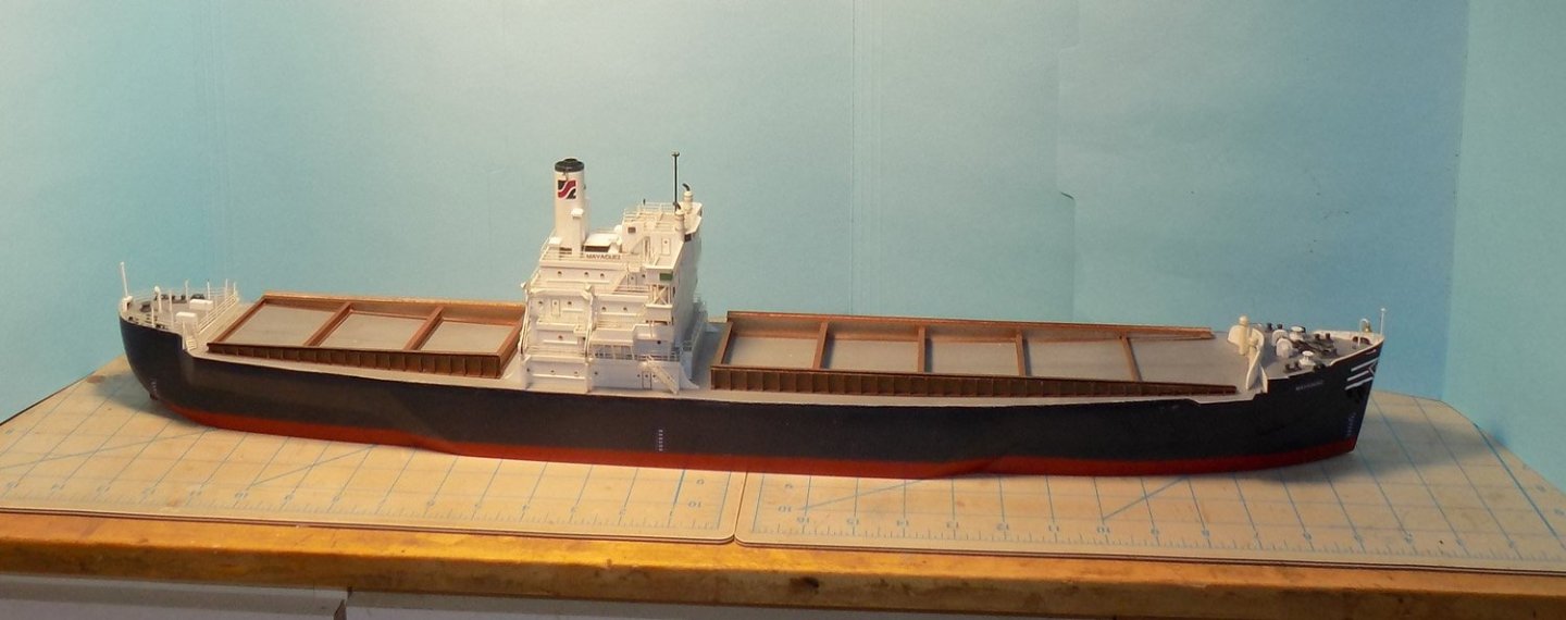
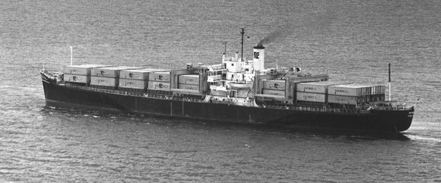
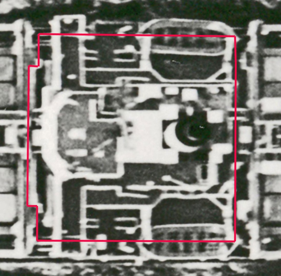
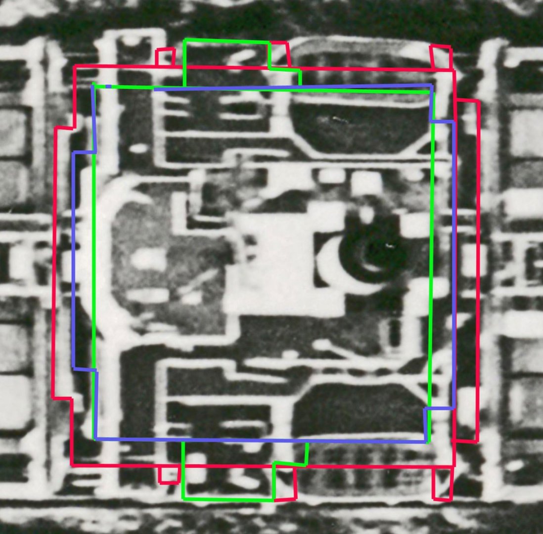
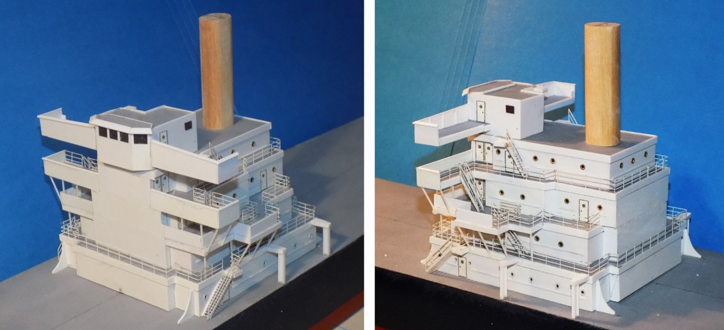
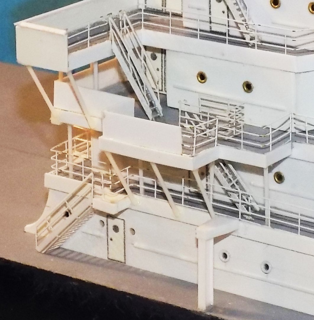
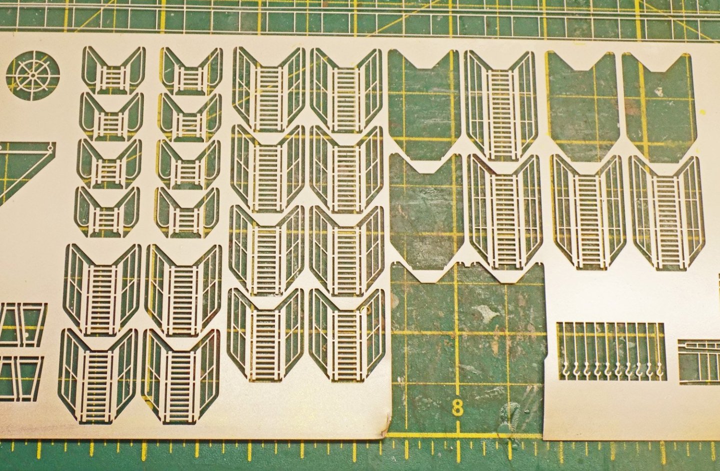
Hello again to all – Thanks for all the likes and comments. Keep them coming. Sorry for the long delay since my last post. I have been fighting a long covid problem that gives me bronchitis which makes me cough, especially at night, so I am having a lot of trouble sleeping. Also I have had cataract surgery on both eyes, which has interfered with writing this blog. But enough about me – back to the model. At the end of the last segment I had completed the basic structure of the hull and was proceeding to work out the superstructure. This began, as with the rest of the model, with a careful examination of the photographs of the ship. Fortunately there were a few images of high resolution like this one of the entire ship. Once enlarged I got a good, if a little fuzzy, picture of the 5 decks and deck houses of the superstructure. I was able to tease out some sense of the complex shapes of the various decks and overhangs. Porthole, door, and stairway locations can be seen, as well as the fact that the top deck house is taller than all the others. In this slightly clearer image I could start the actual analysis of the dimensions and relationships of the shapes that can be seen. I started with the assumption that the original superstructure footprint had been retained, which is the lowest deck house with the curved fillets on either side. Then, when the hull was widened by 8 feet on each side, some changes were made. The supports for the lifeboat davits had to be built out and supported by pillars reaching to the outer edge of the deck. There is an overhang to the right of the lifeboat that extends to the new deck edge and is supported by three diagonal braces. The bridge wings had to be extended, and a number of other small details all had to be changed. These images and analysis was integrated with the information from the overhead photos of the ship taken during the incident and rescue, such as this one from just after the recapture. The image was enlarged and straightened out to give a top view that could be worked with. Always being aware that the image is not precisely taken from directly overhead, I could make out many more details, such as the stairways marked with the red arrows. Hours of staring at these images, individually and collectively, were needed to determine what the various elements and details were. I am still not 100% sure of all of them, and even where I am sure of the shape of things, I am not sure of their purpose. But since this is for the US Merchant Marine Academy, it is good enough for government work. Other images which were not full pictures of the decks and deck houses also informed a number of details of railings, stairways, overhangs, supports, etc. Here, for example, is one of the Marines taking control of the ship. I would not have seen the tall ventilator/filter under the stairs at the side of the bridge except for this picture. So, taking all the information in hand, I laid out the shape of the lowest deck house over the top image. Using this as my basic starting point I laid on the shapes of the stairway platforms and lifeboat davit supports to the first level. Then using the relationships seen in the photos, I drew on the shapes of the second and third decks, deck houses, and overhangs in contrasting colors, giving this image. Based on these drawings I cut ½” planks of basswood to the shapes of the deck houses (less 0.04” all around) and sheathed them with 0.02” styrene (restoring the full sizes). The decks were cut to the full size of the deck houses and painted grey before being edged with styrene. This gave a pleasing delineation to the decks, which can be seen in the photos. The edges extended just a bit above the deck level, making a lip that anchored the photoetched railings when they were added later. Portholes are the brass dollhouse electric circuit pieces, while the handrails are 0.015” round rod. Here the superstructure stack is about half done, with all the upper details still to be done. Here is an enlarged shot of some of the details. Notice the diagonal supports for the overhangs of the second deck and bridge wing. The railings and stairways are photoetched brass from Gold Medal Models’ ocean liner set. It is expensive, but makes for a very convincing impression when painted, folded and installed. The railings come in long frets four scale feet tall (1/4”) with horizontal rails numbering from one to five to be used as needed. The photos of the ship show that the railings mostly have three rails, so these were the frets that were used. They were spray painted gloss white before being cut apart. Unfortunately the paint was a bit brittle, so it chipped off when bent, as can be seen in the last photo, but that was easily touched up later. The stairways come as part of a larger fret with hooks, steering wheels, etc. They have a central length of steps flanked by angled wings for the side railings. They come in three different lengths. Mostly the middle length was used, but occasionally the short or long ones were needed for a particular location. Small adjustments to length were made by trimming the bottom of the stairways. The basic stairway is made by bending up the wings of the piece to form the railings at either side of the steps (left image). But this is meant for use on the ocean liners, so it is wider and less steep than the stairways on merchant ships. To make them steeper the railings are pressed down towards the steps till the supporting posts are vertical when the stairs are at the steeper angle (middle image). Where the stairs had to be narrow, one side railing and some of the width of the steps was cut off and the stairs supported by an added strip of styrene (right image). Work continued on the superstructure with detail added as they were identified in the photos. Note the cross supports between the lower and upper bridge wings and the fact that the front facing of the upper bride wing is taller at the bridge house than it is at the outer end. The funnel has now been sheathed and is set in place so I could determine the location and size of the many details on the upper decks. While this analysis and work on the superstructure continued I was also starting to puzzle out the size and shape of the 96 containers that had to be installed on deck, and how to build them in a reasonably efficient manner. This will be the topic of the next segment. Till then, may your health be better than mine. Dan


-
Hi to all my friends who are following my logs. I am starting another one - scratch building an ocean diorama of the 1975 incident when the SS Mayaguez was siezed by armed gunboats from the communist Khymer Rouge government of Cambodia (which they named Kampuchea). The model was honored with the Jim Roberts' Craftsmanship Award at the Northeast Joint Clubs conference last April. To follow along, just click on the underlined text in my profile for my 'Current Build'. I will try to make it, hopefully, as entertaining and informative as this one. Be well Dan
- 95 replies
-
- 6
-
-
- POW
- Bone model
- (and 2 more)
-
Hi all - Thanks for joining me. I'll try to keep it interesting. Keith - it will be more than one post, but not a full, extensively detailed, build log. I was working to a bit of a deadline and did not stop to take photos of every day's progress. I will show the construction process for many of the more unusual details, but the general construction follows my usual methods shown in other build logs. Druxey - I use plaster of Paris because I am familiar with it. It mixes easily, spreads thinly, and dries to a stiff, hard surface that can still be easily sanded to smooth surfaces with sharp corners and edges. With a final coating of Minwax Wood Hardener it takes on a great deal of strength that stands up to the occasional clumsy ding without a major dent. I am not familiar with gesso, and don't know its properties. It may well be as good or better, but this is the Devil I know. Thanks for your interest. Dan
-
Hi guys - Thanks for joining me here. Yes, this was an interesting subject, if not for the ship herself, but for the historic event. As for the ladders and stairways, these will be covered in detail in upcoming installments. Dan