


shipmodel
-
Posts
908 -
Joined
-
Last visited
Reputation Activity
-

 shipmodel got a reaction from CharlieZardoz in Queen Anne's Revenge 1710 by shipmodel - FINISHED - 1/36 scale
Hello again -
Just back from the doctor, who says that a 'trigger finger' problem that I am having with my right thumb is related to the repetitive nature of the carving work. He told me to lay off for a while, and gave me a cortisone shot into the base of the thumb. Ouch ! And then it didn't work! I don't have much more to do on the first figurehead, so I am going to finish it in easy stages, then work on some larger pieces before going back to the second lion.
Here is a short report on where I am now -
This next phase of the carving is mostly a process of refining the shapes that were defined last time. For this I mostly use a series of diamond abrasive burrs of various shapes. Here is the set, purchased from Micro-Mark some time ago when Chinese tool makers hadn't started taking short cuts with quality. They have held up very well for more than a decade. The long cone in the Dremel is very useful. I use the point for lining out and small details, while the larger diameter of the base of the burr smooths and shapes larger surfaces.
The carving process with these burrs is the same as for the larger bitts - I first define the edges and planes, then refine them by rounding the corners and adjusting the angles of the planes. Raised body parts like the tail and upper arm are given some dimensionality by undercutting them slightly to create a shadow line.
All of the carving is all done by eye at this stage - the Michelangelo method - I just remove whatever doesn't look like the image in my head. Here are a series of shots with the work rotating starboard to port.
The major issue right now is the shape of the head. It is still too broad. In some photos it looks more like a lizard than a lion. You can see that quite clearly in the first enlarged photo below. This was taken with the macro setting on the camera, and some of the problem is exaggerated, but you can see what I mean. In the lower photo I used Photoshop to narrow the image about 15%, and now it looks much more leonine. I will carve it down to get that general shape.
If you haven't figured it out, the teeth are created by simply drilling a series of small holes which define the negative space between the teeth. I may use a small triangular file to refine them, or just leave them as is, since they are all but invisible uness a camera is used to magnify them.
Happy Thanksgiving to all.
Dan
-
 shipmodel reacted to CharlieZardoz in Sultana by CharlieZardoz - Model Shipways - 1:64
I cut out the little paper frames as so and as confirmed by Chuck in the practicum they don't match the actual plans. Based on this I'm wondering if what I need to do is cut the plans up and make templates from the decks etc to better shape hull as well as the paper frames.
-
 shipmodel got a reaction from Salty Sea Dog in Licorne 1755 by mtaylor - 3/16" scale - French Frigate - from Hahn plans - Version 2.0 - TERMINATED
Hi Mark -
Welcome to the wacky and wonderful world of spiling. Although you can get lots of help from various books, and Jim Roberts' is one of the best, it is mostly a question of experience and eyeballing.
One thing that Jim suggested when I was his pupil was to take strips of frosted tape and lay them flat on the hull till the area I was working on was completely covered. Like the planks, the tape will sweep up toward the wale with the curve of the hull and cover previous tape runs. This is a good thing. It shows how much the planks want to bend so I could start to judge how many stealers/drop planks I might need. Also, with the area completely taped I could line out the plank runs in pencil, making as many mistakes as I wanted without consequence. After a while I developed a good sense of how the hull wanted to be planked, and could then much more accurately position my battens to guide the actual wood planks.
On the Licorne I have a feeling, and I could be wrong, that your first batten is too high (towards the keel) at the bow. Judging by eye, the remaining area from the batten to the keel is not wide enough and your lower planks could be crowded and narrow, The only way to be sure of this is to put in all of the battens that you want and then carefully examine them from dead ahead to see if they give you equal spacing. A similar thing goes on at the stern.
Here is a drawing of what I mean. It is from Jim's book, although I have removed his text for clarity.
Remember also that the garboard and first broad strake (the one next to the garboard) are wider than the rest of the planks, and your spiling/batten plan has to take this into account.
This was probably a longer response than you wanted, but I hope that it helps.
Dan
-
 shipmodel got a reaction from lb0190 in Licorne 1755 by mtaylor - 3/16" scale - French Frigate - from Hahn plans - Version 2.0 - TERMINATED
Hi Mark -
Welcome to the wacky and wonderful world of spiling. Although you can get lots of help from various books, and Jim Roberts' is one of the best, it is mostly a question of experience and eyeballing.
One thing that Jim suggested when I was his pupil was to take strips of frosted tape and lay them flat on the hull till the area I was working on was completely covered. Like the planks, the tape will sweep up toward the wale with the curve of the hull and cover previous tape runs. This is a good thing. It shows how much the planks want to bend so I could start to judge how many stealers/drop planks I might need. Also, with the area completely taped I could line out the plank runs in pencil, making as many mistakes as I wanted without consequence. After a while I developed a good sense of how the hull wanted to be planked, and could then much more accurately position my battens to guide the actual wood planks.
On the Licorne I have a feeling, and I could be wrong, that your first batten is too high (towards the keel) at the bow. Judging by eye, the remaining area from the batten to the keel is not wide enough and your lower planks could be crowded and narrow, The only way to be sure of this is to put in all of the battens that you want and then carefully examine them from dead ahead to see if they give you equal spacing. A similar thing goes on at the stern.
Here is a drawing of what I mean. It is from Jim's book, although I have removed his text for clarity.
Remember also that the garboard and first broad strake (the one next to the garboard) are wider than the rest of the planks, and your spiling/batten plan has to take this into account.
This was probably a longer response than you wanted, but I hope that it helps.
Dan
-
 shipmodel got a reaction from Mfelinger in Licorne 1755 by mtaylor - 3/16" scale - French Frigate - from Hahn plans - Version 2.0 - TERMINATED
Hi Mark -
Welcome to the wacky and wonderful world of spiling. Although you can get lots of help from various books, and Jim Roberts' is one of the best, it is mostly a question of experience and eyeballing.
One thing that Jim suggested when I was his pupil was to take strips of frosted tape and lay them flat on the hull till the area I was working on was completely covered. Like the planks, the tape will sweep up toward the wale with the curve of the hull and cover previous tape runs. This is a good thing. It shows how much the planks want to bend so I could start to judge how many stealers/drop planks I might need. Also, with the area completely taped I could line out the plank runs in pencil, making as many mistakes as I wanted without consequence. After a while I developed a good sense of how the hull wanted to be planked, and could then much more accurately position my battens to guide the actual wood planks.
On the Licorne I have a feeling, and I could be wrong, that your first batten is too high (towards the keel) at the bow. Judging by eye, the remaining area from the batten to the keel is not wide enough and your lower planks could be crowded and narrow, The only way to be sure of this is to put in all of the battens that you want and then carefully examine them from dead ahead to see if they give you equal spacing. A similar thing goes on at the stern.
Here is a drawing of what I mean. It is from Jim's book, although I have removed his text for clarity.
Remember also that the garboard and first broad strake (the one next to the garboard) are wider than the rest of the planks, and your spiling/batten plan has to take this into account.
This was probably a longer response than you wanted, but I hope that it helps.
Dan
-
 shipmodel got a reaction from avsjerome2003 in Licorne 1755 by mtaylor - 3/16" scale - French Frigate - from Hahn plans - Version 2.0 - TERMINATED
Hi Mark -
Welcome to the wacky and wonderful world of spiling. Although you can get lots of help from various books, and Jim Roberts' is one of the best, it is mostly a question of experience and eyeballing.
One thing that Jim suggested when I was his pupil was to take strips of frosted tape and lay them flat on the hull till the area I was working on was completely covered. Like the planks, the tape will sweep up toward the wale with the curve of the hull and cover previous tape runs. This is a good thing. It shows how much the planks want to bend so I could start to judge how many stealers/drop planks I might need. Also, with the area completely taped I could line out the plank runs in pencil, making as many mistakes as I wanted without consequence. After a while I developed a good sense of how the hull wanted to be planked, and could then much more accurately position my battens to guide the actual wood planks.
On the Licorne I have a feeling, and I could be wrong, that your first batten is too high (towards the keel) at the bow. Judging by eye, the remaining area from the batten to the keel is not wide enough and your lower planks could be crowded and narrow, The only way to be sure of this is to put in all of the battens that you want and then carefully examine them from dead ahead to see if they give you equal spacing. A similar thing goes on at the stern.
Here is a drawing of what I mean. It is from Jim's book, although I have removed his text for clarity.
Remember also that the garboard and first broad strake (the one next to the garboard) are wider than the rest of the planks, and your spiling/batten plan has to take this into account.
This was probably a longer response than you wanted, but I hope that it helps.
Dan
-
 shipmodel got a reaction from tkay11 in Licorne 1755 by mtaylor - 3/16" scale - French Frigate - from Hahn plans - Version 2.0 - TERMINATED
Hi Mark -
Welcome to the wacky and wonderful world of spiling. Although you can get lots of help from various books, and Jim Roberts' is one of the best, it is mostly a question of experience and eyeballing.
One thing that Jim suggested when I was his pupil was to take strips of frosted tape and lay them flat on the hull till the area I was working on was completely covered. Like the planks, the tape will sweep up toward the wale with the curve of the hull and cover previous tape runs. This is a good thing. It shows how much the planks want to bend so I could start to judge how many stealers/drop planks I might need. Also, with the area completely taped I could line out the plank runs in pencil, making as many mistakes as I wanted without consequence. After a while I developed a good sense of how the hull wanted to be planked, and could then much more accurately position my battens to guide the actual wood planks.
On the Licorne I have a feeling, and I could be wrong, that your first batten is too high (towards the keel) at the bow. Judging by eye, the remaining area from the batten to the keel is not wide enough and your lower planks could be crowded and narrow, The only way to be sure of this is to put in all of the battens that you want and then carefully examine them from dead ahead to see if they give you equal spacing. A similar thing goes on at the stern.
Here is a drawing of what I mean. It is from Jim's book, although I have removed his text for clarity.
Remember also that the garboard and first broad strake (the one next to the garboard) are wider than the rest of the planks, and your spiling/batten plan has to take this into account.
This was probably a longer response than you wanted, but I hope that it helps.
Dan
-
 shipmodel got a reaction from GuntherMT in Queen Anne's Revenge 1710 by shipmodel - FINISHED - 1/36 scale
Build Log 35 - t'gallant sails, boat, swivel guns
Hi again, and welcome to spring -
Back from vacation and back in harness. This installment finishes the square sails, the two topgallant sails; fits out the ship's boat and installs the swivel guns.
The t'gallant sails were made using the same techniques as those for the larger sails. The sail was measured to fit the spar and reach the sheet blocks on the topsail spars. This was laid out on stiffened fabric.
1
The edges were glued, including the overlaps for the tabling. The openings for the cringles were cut out and the sail was cut along the outer edges of the tabling.
2
The bolt rope was installed and the tabling ironed down over it to secure it.
3
And here is the finished sail with reinforcements added to each corner.
4
The sails were laced to their spars and mounted to the model with ties and halyards, parrells, lifts, braces, and sheets, all according to Anderson. Clew blocks and lines were rigged and run, although these sails did not have buntlines or leach lines. Finally the bowlines and their bridles were rigged and run.
4a
These last lines were pretty hard to run. Not only is it getting pretty crowded at the bases of the masts, but it usually took several attempts before I could make the lines run without fouling any previous lines. Here is what the foot of the foremast looks like at this stage.
4b
And here is the model with all square sails set.
5
6
Next the ship's boat was fitted out. First came the oars. I made 12 of them to match the number of oarlocks on the sheer. In the photo you can see the four steps in their construction. The first three on the left are cut out roughly on the table saw. The next three have been roughly shaped using a sanding drum in the Dremel. The next three have been smoothed and refined, with a groove which sets off the handle. The final three have been final sanded, finished, and have had a rope sleeve added which would protect the oar from chafing on the rowlock.
7
Once the photo was taken the full set of oars was finished, then tied into bundles of six and lashed to a thwart.
8
A simple mast was made up to fit in the mast step. A spar was estimated and a sail made up to fit, then laced to the spar. The mast and spar were lashed together and to a thwart. Several belaying points were set into the sheer for stays and sail handling lines. Here is the finished boat on its cradles, although not permanently secured yet.
9
The final fittings in this segment are the swivel guns. It is known that Blackbeard added a number of these useful weapons to the armament of the QAR, and one has been recovered in the excavation of the site. Taking its measurements, a set of bronze colored barrels were located in the aftermarket that closely matched the size and shape of the artifact.
To mount them, a set of simple forked stanchions were made up from brass. Here are the various pieces and how they go together.
10
Once the prototype was acceptable, the pieces were soldered together, the brass blackened, and the barrels mounted.
11
There are four on each side on the caprails, and one each in the main and fore tops.
12
So here is the current status.
13
Next, the staysails and maybe the anchors.
Be well
Dan
-
 shipmodel got a reaction from popash42 in Queen Anne's Revenge 1710 by shipmodel - FINISHED - 1/36 scale
Hi all, and thanks for the likes and compliments.
Matt - I don't have any definitive research or authority for my setup, but I mounted the swivel guns in the tops on blocks set toward the forward edge on both sides, giving them the best field of fire once the topsails are raised. However, only one of the blocks is used at any one time, on the theory that it would have been relatively simple to move the gun from one side to the other, and having two of them at once would be additional weight in the top that was not needed. That's my story and I'm sticking to it.
Here is the foretop with the gun mounted on the starboard side.
Hope that explains it.
Dan
-

 shipmodel got a reaction from scrubbyj427 in Queen Anne's Revenge 1710 by shipmodel - FINISHED - 1/36 scale
Hi all and thanks for the likes and comments.
At the end of the last segment I had finished and hung the square sails. Now I turned to the staysails, most of which will be shown furled.
The sails were made up much like the square sails, but as triangles rather than trapezoids. Here are the two from the first set that were made. They were discarded because the panel lines are wrong. The pattern with a central seam and angled panels is much more modern than would have been in use in 1710. I made a hasty assumption before checking my sources.
1
So here is the redone main staysail. It is reduced in size for purposes of furling, but is otherwise appropriately rigged. As explained by R.C. Anderson, the lines and blocks for the foreyard braces would have interfered with the staysail sliding up the stay. So a false stay was rigged under the mainstay and the sail is spiral laced to it.
2
The lower end of the false stay is secured to the foremast by a collar that rides just under the thumb cleat for the forestay (indicated by the arrow on the left). A small deadeye is turned into the collar and a matching one seized into the lower end of the false stay. The lanyard between them is tightened and the running end is frapped around it (see the arrow on the right). Lacing this in, around and through the previously rigged lines was one of the most delicate operations I have ever performed in my years of modeling. Suffice to say that I will pre-rig this next time.
3
The upper end of the false stay is comparatively easy. There is an eye splice turned into the end of the line, which is then seized to the mainstay just above the euphroe lashing. A single block is seized to the stay between the euphroe and the mouse to run the uphaul line for the staysail.
4
Once the sail was rigged, the lines were loosened, the sail misted with water and drawn down toward the foremast. It was furled, twisted, and wrapped with one leg of the sheet line, the other was used to secure the furled sail at the deck to one of the deck cleats. When I was happy with the look it was painted with matte finish to stiffen it.
5
Similarly, the main topmast staysail was rigged on its false stay.
6
The mizzen stays do not have any brace blocks rigged to them, so the staysails do not need a false stay. Here is the mizzen staysail.
7
And here is the mizzen topmast staysail.
8
The fore staysail was done in the same way.
8a
The fore topmast staysail was set and shown billowed, its shape mirroring and complimenting the mizzen lateen sail. I first ran it down the t’gallant stay, but this did not seem right. First, it put it too far forward to look good to my eye. Maybe more important, rigging it that way would have one of the largest sails being run between one of the smallest diameter masts and the end of the jib boom, also not that large a timber. This is a broken masthead waiting to happen. Instead, I looked at some contemporary French models and usually saw a line running from the topmast head to the end of the jib boom. This looked much more likely, and gave the sail a nice angle and shape.
8b
So here is the model with all sails set and rigged.
9
Next I turned to the flag. Although no one truly knows what his flag looked like, the Internet has one that is called the Blackbeard flag. It is a demon holding a glass in one hand and a spear in the other, aimed at a red heart with three red dots in the lower corner. This was the one selected by the museum.
I took the image and imported it into my computer. Using Photoshop I resized it, then used the skew function to bring down the lower outer corner of the flag. This helps it to hang more naturally without a buildup of material. A copy was saved and reversed, then both were combined into one image.
10
The double image was printed out on a piece of paper. A piece of thin fabric large enough to cover the image with some excess all around was stiffened, then taped over the upper image and run through the printer. This put an image on the first side. The fabric was cut loose, turned over and positioned over the lower image. Since the fabric was somewhat transparent it was easy to locate it exactly over the previously printed image. Again it was taped down on all sides and printed again.
11
After allowing the ink to dry for 48 hours the flag was stiffened to lock in the ink, then cut out, leaving a bit of excess along the fly edge. The hauling line was set in and the flap glued over it and ironed down. The ensign staff was built up with a small block at the top and a cleat mounted at easy reaching height for a man. With the staff mounted the flag was misted and curled.
12
So here is the model almost done.
14
The next segment should be the last. Only the stern lantern to build and the anchors to mount.
Back soon.
Dan
-
 shipmodel got a reaction from Elmer Cornish in Licorne 1755 by mtaylor - 3/16" scale - French Frigate - from Hahn plans - Version 2.0 - TERMINATED
Hi Mark -
Welcome to the wacky and wonderful world of spiling. Although you can get lots of help from various books, and Jim Roberts' is one of the best, it is mostly a question of experience and eyeballing.
One thing that Jim suggested when I was his pupil was to take strips of frosted tape and lay them flat on the hull till the area I was working on was completely covered. Like the planks, the tape will sweep up toward the wale with the curve of the hull and cover previous tape runs. This is a good thing. It shows how much the planks want to bend so I could start to judge how many stealers/drop planks I might need. Also, with the area completely taped I could line out the plank runs in pencil, making as many mistakes as I wanted without consequence. After a while I developed a good sense of how the hull wanted to be planked, and could then much more accurately position my battens to guide the actual wood planks.
On the Licorne I have a feeling, and I could be wrong, that your first batten is too high (towards the keel) at the bow. Judging by eye, the remaining area from the batten to the keel is not wide enough and your lower planks could be crowded and narrow, The only way to be sure of this is to put in all of the battens that you want and then carefully examine them from dead ahead to see if they give you equal spacing. A similar thing goes on at the stern.
Here is a drawing of what I mean. It is from Jim's book, although I have removed his text for clarity.
Remember also that the garboard and first broad strake (the one next to the garboard) are wider than the rest of the planks, and your spiling/batten plan has to take this into account.
This was probably a longer response than you wanted, but I hope that it helps.
Dan
-
 shipmodel got a reaction from mikegerber in Licorne 1755 by mtaylor - 3/16" scale - French Frigate - from Hahn plans - Version 2.0 - TERMINATED
Hi Mark -
Welcome to the wacky and wonderful world of spiling. Although you can get lots of help from various books, and Jim Roberts' is one of the best, it is mostly a question of experience and eyeballing.
One thing that Jim suggested when I was his pupil was to take strips of frosted tape and lay them flat on the hull till the area I was working on was completely covered. Like the planks, the tape will sweep up toward the wale with the curve of the hull and cover previous tape runs. This is a good thing. It shows how much the planks want to bend so I could start to judge how many stealers/drop planks I might need. Also, with the area completely taped I could line out the plank runs in pencil, making as many mistakes as I wanted without consequence. After a while I developed a good sense of how the hull wanted to be planked, and could then much more accurately position my battens to guide the actual wood planks.
On the Licorne I have a feeling, and I could be wrong, that your first batten is too high (towards the keel) at the bow. Judging by eye, the remaining area from the batten to the keel is not wide enough and your lower planks could be crowded and narrow, The only way to be sure of this is to put in all of the battens that you want and then carefully examine them from dead ahead to see if they give you equal spacing. A similar thing goes on at the stern.
Here is a drawing of what I mean. It is from Jim's book, although I have removed his text for clarity.
Remember also that the garboard and first broad strake (the one next to the garboard) are wider than the rest of the planks, and your spiling/batten plan has to take this into account.
This was probably a longer response than you wanted, but I hope that it helps.
Dan
-
 shipmodel got a reaction from Piet in Licorne 1755 by mtaylor - 3/16" scale - French Frigate - from Hahn plans - Version 2.0 - TERMINATED
Hi Mark -
Welcome to the wacky and wonderful world of spiling. Although you can get lots of help from various books, and Jim Roberts' is one of the best, it is mostly a question of experience and eyeballing.
One thing that Jim suggested when I was his pupil was to take strips of frosted tape and lay them flat on the hull till the area I was working on was completely covered. Like the planks, the tape will sweep up toward the wale with the curve of the hull and cover previous tape runs. This is a good thing. It shows how much the planks want to bend so I could start to judge how many stealers/drop planks I might need. Also, with the area completely taped I could line out the plank runs in pencil, making as many mistakes as I wanted without consequence. After a while I developed a good sense of how the hull wanted to be planked, and could then much more accurately position my battens to guide the actual wood planks.
On the Licorne I have a feeling, and I could be wrong, that your first batten is too high (towards the keel) at the bow. Judging by eye, the remaining area from the batten to the keel is not wide enough and your lower planks could be crowded and narrow, The only way to be sure of this is to put in all of the battens that you want and then carefully examine them from dead ahead to see if they give you equal spacing. A similar thing goes on at the stern.
Here is a drawing of what I mean. It is from Jim's book, although I have removed his text for clarity.
Remember also that the garboard and first broad strake (the one next to the garboard) are wider than the rest of the planks, and your spiling/batten plan has to take this into account.
This was probably a longer response than you wanted, but I hope that it helps.
Dan
-
 shipmodel got a reaction from CiscoH in Queen Anne's Revenge 1710 by shipmodel - FINISHED - 1/36 scale
Hi again, and thanks for the likes and compliments.
It is going well, I think. I am trying to create the look of a working ship, rather than one fresh off the building ways.
Now that the foredeck is installed, I turned to the waist. With the cannon rigged out they can be covered by the gangways. But first I decided to put in the ropes that go through the hull and belay below the gangways. It would have been much harder to do them with the gangways in place. These are the main course tack that goes through the chesstree, and the two sheets that go through the sheaves in the hull.
These lines will be some of the larger running rigging ropes and, because of their locations, some of the more visually prominent ones. They have to be good quality and look like miniature rope. I could have laid them up on my ropewalk, but I have a few spools of treasured Cuttyhunk Irish linen line (which is no longer available for any price). The Zane Grey and Natural colors are too white, but a quick run through Minwax wood stain in Ipswitch Pine color makes them look the right shade.
1
Even examined closely this gives them the look of miniature rope.
2
I fed the line through the hull openings. The larger line (C-21) was used for the tacks which belayed to cleats, while the smaller one (C-12) was for the sheets.which belayed to the staghorn kevil.
3
Although each line is tied off properly, they were all further secured with dilute white glue. When dry the ends were nipped off and hidden by separate rope coils. I make these on a simple jig. A block of soft wood - basswood in this case, but it could be balsa - has several holes drilled in the top face and one or two holes in the front face in the same line. Removable brass pegs fit into the holes and everything is given several coats of clear finish to keep glue from sticking to it. Then matching lines are wrapped around the pegs with the ends friction fit into notches in the jig.
4
As I wrap I randomly make larger and smaller loops and even the occasional figure eight. When I have the look that I want, the coils are painted with dilute white glue. Actually, they are first wet down with water, which helps the dilute glue to penetrate the line rather than having it sit on the surface. When the glue is dry the top peg is removed and the coil peeled up from the jig and trimmed. Using dilute glue means that the coils are flexible while still holding their shape.
5
The coils are hung over the belaying points, teased into position where they look like they are hanging with the force of gravity, and secured with white glue.
6
7
In the photos you can see the supporting knees for the gangways. These were made as before by cutting and shaping a stick and then parting off individual ones. After locating and installing the forward and aft ones, the gangways were glued in, then the middle two knees for each gangway were installed. In the photo you can see the ropes that feed through the hull. I left what I hope is more than enough to reach to the sails, but we will see when the rigging is installed.
8
The final fittings in the waist were the four ladders from the gun deck up to the gangways. They were wider at the base than at the top, and were built up as has been detailed before as a stack, then parted off.
9
After individual ladders were parted off they were cleaned up, stained and installed.
10
Now that the waist was complete, I turned to the quarterdeck. The railing that was built up last time was installed, then the whipstaff. For those not familiar, this is an obsolete steering device that predated the wheel. It consisted of a rotating fitting called a rowel set into the deck through which a staff passed before it hooked into the end of the tiller arm. Moving the staff port or starboard turned the rudder. It was not very efficient, but then most steering was done with the sails during this time.
10a
A hole was drilled in the deck and a piece of pear cut and sanded to fit. The fore/aft slot for the rowel was carved into the pear piece, as were indentations for the staff clearance athwartships. The rowel was turned from maple, and the hole drilled to allow the staff to have a sliding fit. I set the staff at an offset angle and glued it in place.
11
You can also see the ladders from the quarterdeck to the poop deck on the roof of the captain's cabin. These were made up as before, just a little taller than the gangway ladders. Similarly, the post with sheaves for the lateen halyard was made like the fore and mainyard halyard fittings. Along the bulwarks are staghorns and pinrails as drawn by Budriot. I am not completely sold on the pinrails, which do not appear anywhere else on the ship, but they are certainly needed for belaying points.
The four 4-pounder cannon were rigged and installed like the 6-pounders on the gun deck.
12
Now the deck fittings that were made up almost a year ago could be installed. These were the companionway house, the officers' bench in front of it, and the two small binnacles.
13
The ship is now ready for rigging, which will start next month.
14
Until then, happy Thanksgiving to all and to your families.
Dan
-
 shipmodel got a reaction from Landlubber Mike in Licorne 1755 by mtaylor - 3/16" scale - French Frigate - from Hahn plans - Version 2.0 - TERMINATED
Hi Mark -
Coming along quite nicely. I can see how your planking skills are improving all the time as you get more experience and work your way up the learning curve.
As for sequencing, I recommend that you plank the stern first. This is how it was done in actual practice, so the run of the hull planks would overlap the hood ends of the stern planking, reducing the chance that water action would loosen the stern planks. It is also easier to do, because you can sand the ends of the stern planks flush with the final ribs, then simply run the hull planks over and past them before trimming and sanding flush with the face of the stern planks. If you have Zu Mondfeld's book, look at his discussion of stern planking (pages 96-97 in my edition).
Looking forward to watching you progress.
Dan
.
-
 shipmodel got a reaction from IgorSky in Licorne 1755 by mtaylor - 3/16" scale - French Frigate - from Hahn plans - Version 2.0 - TERMINATED
Hi Mark -
Coming along quite nicely. I can see how your planking skills are improving all the time as you get more experience and work your way up the learning curve.
As for sequencing, I recommend that you plank the stern first. This is how it was done in actual practice, so the run of the hull planks would overlap the hood ends of the stern planking, reducing the chance that water action would loosen the stern planks. It is also easier to do, because you can sand the ends of the stern planks flush with the final ribs, then simply run the hull planks over and past them before trimming and sanding flush with the face of the stern planks. If you have Zu Mondfeld's book, look at his discussion of stern planking (pages 96-97 in my edition).
Looking forward to watching you progress.
Dan
.
-
shipmodel got a reaction from Piet in Licorne 1755 by mtaylor - 3/16" scale - French Frigate - from Hahn plans - Version 2.0 - TERMINATED
Hi Mark -
Coming along quite nicely. I can see how your planking skills are improving all the time as you get more experience and work your way up the learning curve.
As for sequencing, I recommend that you plank the stern first. This is how it was done in actual practice, so the run of the hull planks would overlap the hood ends of the stern planking, reducing the chance that water action would loosen the stern planks. It is also easier to do, because you can sand the ends of the stern planks flush with the final ribs, then simply run the hull planks over and past them before trimming and sanding flush with the face of the stern planks. If you have Zu Mondfeld's book, look at his discussion of stern planking (pages 96-97 in my edition).
Looking forward to watching you progress.
Dan
.
-
 shipmodel got a reaction from mtaylor in Licorne 1755 by mtaylor - 3/16" scale - French Frigate - from Hahn plans - Version 2.0 - TERMINATED
Hi Mark -
Coming along quite nicely. I can see how your planking skills are improving all the time as you get more experience and work your way up the learning curve.
As for sequencing, I recommend that you plank the stern first. This is how it was done in actual practice, so the run of the hull planks would overlap the hood ends of the stern planking, reducing the chance that water action would loosen the stern planks. It is also easier to do, because you can sand the ends of the stern planks flush with the final ribs, then simply run the hull planks over and past them before trimming and sanding flush with the face of the stern planks. If you have Zu Mondfeld's book, look at his discussion of stern planking (pages 96-97 in my edition).
Looking forward to watching you progress.
Dan
.
-
 shipmodel got a reaction from Jack12477 in Licorne 1755 by mtaylor - 3/16" scale - French Frigate - from Hahn plans - Version 2.0 - TERMINATED
Hi Mark -
Coming along quite nicely. I can see how your planking skills are improving all the time as you get more experience and work your way up the learning curve.
As for sequencing, I recommend that you plank the stern first. This is how it was done in actual practice, so the run of the hull planks would overlap the hood ends of the stern planking, reducing the chance that water action would loosen the stern planks. It is also easier to do, because you can sand the ends of the stern planks flush with the final ribs, then simply run the hull planks over and past them before trimming and sanding flush with the face of the stern planks. If you have Zu Mondfeld's book, look at his discussion of stern planking (pages 96-97 in my edition).
Looking forward to watching you progress.
Dan
.
-
 shipmodel got a reaction from Canute in Licorne 1755 by mtaylor - 3/16" scale - French Frigate - from Hahn plans - Version 2.0 - TERMINATED
Hi Mark -
Coming along quite nicely. I can see how your planking skills are improving all the time as you get more experience and work your way up the learning curve.
As for sequencing, I recommend that you plank the stern first. This is how it was done in actual practice, so the run of the hull planks would overlap the hood ends of the stern planking, reducing the chance that water action would loosen the stern planks. It is also easier to do, because you can sand the ends of the stern planks flush with the final ribs, then simply run the hull planks over and past them before trimming and sanding flush with the face of the stern planks. If you have Zu Mondfeld's book, look at his discussion of stern planking (pages 96-97 in my edition).
Looking forward to watching you progress.
Dan
.
-
 shipmodel got a reaction from GLakie in Licorne 1755 by mtaylor - 3/16" scale - French Frigate - from Hahn plans - Version 2.0 - TERMINATED
Hi Mark -
Coming along quite nicely. I can see how your planking skills are improving all the time as you get more experience and work your way up the learning curve.
As for sequencing, I recommend that you plank the stern first. This is how it was done in actual practice, so the run of the hull planks would overlap the hood ends of the stern planking, reducing the chance that water action would loosen the stern planks. It is also easier to do, because you can sand the ends of the stern planks flush with the final ribs, then simply run the hull planks over and past them before trimming and sanding flush with the face of the stern planks. If you have Zu Mondfeld's book, look at his discussion of stern planking (pages 96-97 in my edition).
Looking forward to watching you progress.
Dan
.
-
shipmodel reacted to gjdale in Bomb Vessel Granado 1742 by gjdale - FINISHED - 1/48 - Cross-Section
It's been a while since the last update. Recovery from my hip surgery has certainly slowed things down a little, but I have managed to make some progress. The next stage was construction of the Mortar Pit.
Construction of the Mortar Pit
Construction of the Mortar Pit commences with the six Mortar Pit Deck Beams that sit atop the Shell Room. These were cut from 1/4" Pear stock. Six rectangular blanks of identical size were cut and then spot glued together. A single paper pattern for the beams was then glued on to the gang of blanks and the notches for the Shell Room headers (5/16”) and the Mortar Pit Boundary Timbers (1/4”) were cut on the mill to take advantage of the still square faces. The round-up of the beams was then shaped using the spindle sander for the inside curve and the disc sander for the outside curve. After test fitting, the Deck Beams were used as additional support to ensure the Shell Room was squared up for final fixing. Once the Shell Room was securely fastened, the Beams were given a coat of Wipe-On Poly and glued in place.
The Mortar Pit itself is fairly straightforward construction, consisting of two Boundary Timbers of 1/4” x 5/16” Pear, a Primary Layer of planking (3/16” Holly) and a Secondary Layer of planking (1/8” Holly). I decided to use pencil along the plank edges to simulate the caulking with these decks, rather than the black paper used on the deck of the Shell Room, partly because I was concerned about glue adhesion, and partly because I wanted to see what it looked like. Once again, the “drill and fill” method was used for simulating treenails. In retrospect, I should have sealed the Holly before applying the filler for the treenails as some of the filler has gotten into the grain of the deck and slightly discoloured it. Here are the component parts prior to receiving a couple of coats of Wipe-On Poly.
The Primary planking has a 1/8” brass spigot inserted – this will locate the base of the turntable in a later stage of construction. The Secondary planking has a circular cut out for the turntable. This was formed by cutting roughly to shape on the Scroll saw, and then finishing on the spindle sander.
Once both decks had been completed, it was a fairly simple case of finessing them to size to fit the space defined by the Boundary timbers. Here are a few pics of the completed Mortar Pit in place:
Next up, fitting of the Upper Deck Clamps and preparation for construction of the Upper Deck. Stay tuned.....
-
shipmodel got a reaction from popash42 in Queen Anne's Revenge 1710 by shipmodel - FINISHED - 1/36 scale
Hi all and thanks for the likes and comments.
At the end of the last segment I had finished and hung the square sails. Now I turned to the staysails, most of which will be shown furled.
The sails were made up much like the square sails, but as triangles rather than trapezoids. Here are the two from the first set that were made. They were discarded because the panel lines are wrong. The pattern with a central seam and angled panels is much more modern than would have been in use in 1710. I made a hasty assumption before checking my sources.
1
So here is the redone main staysail. It is reduced in size for purposes of furling, but is otherwise appropriately rigged. As explained by R.C. Anderson, the lines and blocks for the foreyard braces would have interfered with the staysail sliding up the stay. So a false stay was rigged under the mainstay and the sail is spiral laced to it.
2
The lower end of the false stay is secured to the foremast by a collar that rides just under the thumb cleat for the forestay (indicated by the arrow on the left). A small deadeye is turned into the collar and a matching one seized into the lower end of the false stay. The lanyard between them is tightened and the running end is frapped around it (see the arrow on the right). Lacing this in, around and through the previously rigged lines was one of the most delicate operations I have ever performed in my years of modeling. Suffice to say that I will pre-rig this next time.
3
The upper end of the false stay is comparatively easy. There is an eye splice turned into the end of the line, which is then seized to the mainstay just above the euphroe lashing. A single block is seized to the stay between the euphroe and the mouse to run the uphaul line for the staysail.
4
Once the sail was rigged, the lines were loosened, the sail misted with water and drawn down toward the foremast. It was furled, twisted, and wrapped with one leg of the sheet line, the other was used to secure the furled sail at the deck to one of the deck cleats. When I was happy with the look it was painted with matte finish to stiffen it.
5
Similarly, the main topmast staysail was rigged on its false stay.
6
The mizzen stays do not have any brace blocks rigged to them, so the staysails do not need a false stay. Here is the mizzen staysail.
7
And here is the mizzen topmast staysail.
8
The fore staysail was done in the same way.
8a
The fore topmast staysail was set and shown billowed, its shape mirroring and complimenting the mizzen lateen sail. I first ran it down the t’gallant stay, but this did not seem right. First, it put it too far forward to look good to my eye. Maybe more important, rigging it that way would have one of the largest sails being run between one of the smallest diameter masts and the end of the jib boom, also not that large a timber. This is a broken masthead waiting to happen. Instead, I looked at some contemporary French models and usually saw a line running from the topmast head to the end of the jib boom. This looked much more likely, and gave the sail a nice angle and shape.
8b
So here is the model with all sails set and rigged.
9
Next I turned to the flag. Although no one truly knows what his flag looked like, the Internet has one that is called the Blackbeard flag. It is a demon holding a glass in one hand and a spear in the other, aimed at a red heart with three red dots in the lower corner. This was the one selected by the museum.
I took the image and imported it into my computer. Using Photoshop I resized it, then used the skew function to bring down the lower outer corner of the flag. This helps it to hang more naturally without a buildup of material. A copy was saved and reversed, then both were combined into one image.
10
The double image was printed out on a piece of paper. A piece of thin fabric large enough to cover the image with some excess all around was stiffened, then taped over the upper image and run through the printer. This put an image on the first side. The fabric was cut loose, turned over and positioned over the lower image. Since the fabric was somewhat transparent it was easy to locate it exactly over the previously printed image. Again it was taped down on all sides and printed again.
11
After allowing the ink to dry for 48 hours the flag was stiffened to lock in the ink, then cut out, leaving a bit of excess along the fly edge. The hauling line was set in and the flap glued over it and ironed down. The ensign staff was built up with a small block at the top and a cleat mounted at easy reaching height for a man. With the staff mounted the flag was misted and curled.
12
So here is the model almost done.
14
The next segment should be the last. Only the stern lantern to build and the anchors to mount.
Back soon.
Dan
-
shipmodel got a reaction from scrubbyj427 in Queen Anne's Revenge 1710 by shipmodel - FINISHED - 1/36 scale
Build log 34 – main, mizzen topsail, bell
Hi to all from snowy Brooklyn. I know that we have not had anything to compare with our daughter in Boston or son in Detroit, much less those of you who live in Canada or the northern tier of the USA, but between Brooklyn and Albany I have had more than enough of this winter !! So here is a quick update before SWMBO and I leave for a week on a warm island.
The last segment ended with hanging and rigging the fore topsail.
#
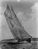
Since then I have made, hung and rigged the main topsail. Nothing original here, just used the same techniques as on the fore topsail.
1
The pair look good, especially when backlit.
2
And here is the full model with the two large topsails.
3
One of the few details on deck that I had not done was the ship’s brass bell. One has been located in the excavation, so I had to include it. I hunted through all the usual sources, including several that said they had ones the right size. But when it came time to order them, there were none to be had. Finally a friend in the NY club and on this list, JerseyCityFrankie, found ones in a jewelry and beading supply house. Toho Shoji, Inc. has a lot of wire, threads, beads, and other items that can be useful. Check out their website at tohoshoji-ny.com. Anyway, here is the 10mm size installed in the belfry at the break of the foredeck.
4
I made the mizzen topsail, but have only hitched it to the mast with the parrell and the tye/halyard. I ran out of properly sized blocks from Warner Woods West, but Lloyd is sending me some more. The break therefore comes at a good time. So here is the model with the three topsails.
5
6
Thanks to all for likes and comments. Stay warm and be well.
Back soon
Dan
-
 shipmodel got a reaction from the learner in Queen Anne's Revenge 1710 by shipmodel - FINISHED - 1/36 scale
Hi all and thanks for the likes and comments.
At the end of the last segment I had finished and hung the square sails. Now I turned to the staysails, most of which will be shown furled.
The sails were made up much like the square sails, but as triangles rather than trapezoids. Here are the two from the first set that were made. They were discarded because the panel lines are wrong. The pattern with a central seam and angled panels is much more modern than would have been in use in 1710. I made a hasty assumption before checking my sources.
1
So here is the redone main staysail. It is reduced in size for purposes of furling, but is otherwise appropriately rigged. As explained by R.C. Anderson, the lines and blocks for the foreyard braces would have interfered with the staysail sliding up the stay. So a false stay was rigged under the mainstay and the sail is spiral laced to it.
2
The lower end of the false stay is secured to the foremast by a collar that rides just under the thumb cleat for the forestay (indicated by the arrow on the left). A small deadeye is turned into the collar and a matching one seized into the lower end of the false stay. The lanyard between them is tightened and the running end is frapped around it (see the arrow on the right). Lacing this in, around and through the previously rigged lines was one of the most delicate operations I have ever performed in my years of modeling. Suffice to say that I will pre-rig this next time.
3
The upper end of the false stay is comparatively easy. There is an eye splice turned into the end of the line, which is then seized to the mainstay just above the euphroe lashing. A single block is seized to the stay between the euphroe and the mouse to run the uphaul line for the staysail.
4
Once the sail was rigged, the lines were loosened, the sail misted with water and drawn down toward the foremast. It was furled, twisted, and wrapped with one leg of the sheet line, the other was used to secure the furled sail at the deck to one of the deck cleats. When I was happy with the look it was painted with matte finish to stiffen it.
5
Similarly, the main topmast staysail was rigged on its false stay.
6
The mizzen stays do not have any brace blocks rigged to them, so the staysails do not need a false stay. Here is the mizzen staysail.
7
And here is the mizzen topmast staysail.
8
The fore staysail was done in the same way.
8a
The fore topmast staysail was set and shown billowed, its shape mirroring and complimenting the mizzen lateen sail. I first ran it down the t’gallant stay, but this did not seem right. First, it put it too far forward to look good to my eye. Maybe more important, rigging it that way would have one of the largest sails being run between one of the smallest diameter masts and the end of the jib boom, also not that large a timber. This is a broken masthead waiting to happen. Instead, I looked at some contemporary French models and usually saw a line running from the topmast head to the end of the jib boom. This looked much more likely, and gave the sail a nice angle and shape.
8b
So here is the model with all sails set and rigged.
9
Next I turned to the flag. Although no one truly knows what his flag looked like, the Internet has one that is called the Blackbeard flag. It is a demon holding a glass in one hand and a spear in the other, aimed at a red heart with three red dots in the lower corner. This was the one selected by the museum.
I took the image and imported it into my computer. Using Photoshop I resized it, then used the skew function to bring down the lower outer corner of the flag. This helps it to hang more naturally without a buildup of material. A copy was saved and reversed, then both were combined into one image.
10
The double image was printed out on a piece of paper. A piece of thin fabric large enough to cover the image with some excess all around was stiffened, then taped over the upper image and run through the printer. This put an image on the first side. The fabric was cut loose, turned over and positioned over the lower image. Since the fabric was somewhat transparent it was easy to locate it exactly over the previously printed image. Again it was taped down on all sides and printed again.
11
After allowing the ink to dry for 48 hours the flag was stiffened to lock in the ink, then cut out, leaving a bit of excess along the fly edge. The hauling line was set in and the flap glued over it and ironed down. The ensign staff was built up with a small block at the top and a cleat mounted at easy reaching height for a man. With the staff mounted the flag was misted and curled.
12
So here is the model almost done.
14
The next segment should be the last. Only the stern lantern to build and the anchors to mount.
Back soon.
Dan