


CPDDET
-
Posts
1,194 -
Joined
-
Last visited
Content Type
Profiles
Forums
Gallery
Events
Everything posted by CPDDET
-
 Thanks Phil. Glad to be back, finally.
 -
It won't be long and I'll be painting the hull of my Bluenose build. While spray painting would be much quicker, easier and provide a nice finish, I'm thinking of brushing the hull. Anyone who has seen the hulls of wooden ships can attest to the fact that the paint jobs are pretty rough looking. Large brush strokes are very noticeable. So I'm looking for some tips and clues on the best way to paint such large areas with acrylic paints. Does the entire hull need to be done all at once or can I stop and resume at a later time? Should the paint be thinned more that usual and plan on 2 coats? I would think paint extender is a must? How large a brush to use? Any advice would be much appreciated. Dave
-
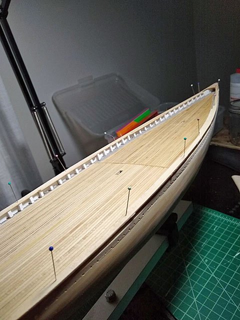
It’s been awhile since my last post. Butting the flowers and lawn to bed for the winter has taken up time, as well as 2 early season snow falls. We got about 4 inches on Halloween and another 4 inches the day before yesterday. I’ve also been spending lots of time choosing a new insurance and drug plan. Now that things have quieted down somewhat I’m able to get back to the build. I finished off the port side cap rail Then I pinned the finished port rail on the second rough cut and outlined it Here are the finished port and starboard cap rails I decided to use Titebond III to allow a bit more work time. I worked from aft forward, putting dabs of glue on top of each frame and pinning it in place as I moved forward. This allowed me to very slightly bend or straiten the cap rails, aligning them with the inbound edge of the frames as I went along. Once the glue dries I will lightly sand the outboard edge of the cap rails to achieve the desired 1/32 inch overhang I’ll have to do some wood filling and sanding where the cap rails meet the bow and stern pieces. I didn’t cut the cap rail ends to match the “S” curve in the bow and stern piece, choosing to butt the edges. But if I had to do it again I would use a short, perhaps an inch or so, piece of cap rail and match the “S” curve and then butt the cap rail to that. Always seems I thing of a better way of doing things after the fact, just part of the learning curve I guess.
- 389 replies
-
- 3
-

-
- bluenose
- model shipways
- (and 1 more)
-
That was my thought. I'm contemplating my first power cutting tool (besides my Dremel) and was looking at the Wonder Cutter. But not sure what I'd get the most use from. Table saw? Scroll saw? Band saw? Miter/chop saw? BTW, Happy Halloween to all
-
Anyone had experience with this tool? I did a search on the forum but nothing came up. https://www.micromark.com/Wondercutter Dave
-
Magnifying headset advice....
CPDDET replied to CPDDET's topic in Modeling tools and Workshop Equipment
Thanks for the guidance! -
Magnifying headset advice....
CPDDET replied to CPDDET's topic in Modeling tools and Workshop Equipment
Sounds like you have a good grasp of what I'm looking for. Hopefully someone with experience can advise us. -
Looking for advice on magnifier headset. Would like to purchase magnifier headset and looking for advice on brand and magnification. Dave
-
Thanks for the reminder, Dave. Just about have the port side cap rail formed. Will post a pic when its done. Dave
-
Looking very nice so far, Pat. I'll be following along.
-
Pat, Thanks for the comment on the cap rails, they are still a work in progress. And thanks for making me feel so welcome last night. Walking into a room full of strangers can be a bit intimidating, but you made me feel comfortable and welcomed. See you next month!
-
Best tool for Cutting Windows for gunports
CPDDET replied to michael101's topic in Modeling tools and Workshop Equipment
That's a great tip Wallace, I can see where your method would come in handy in a variety of situations. Thanks! -
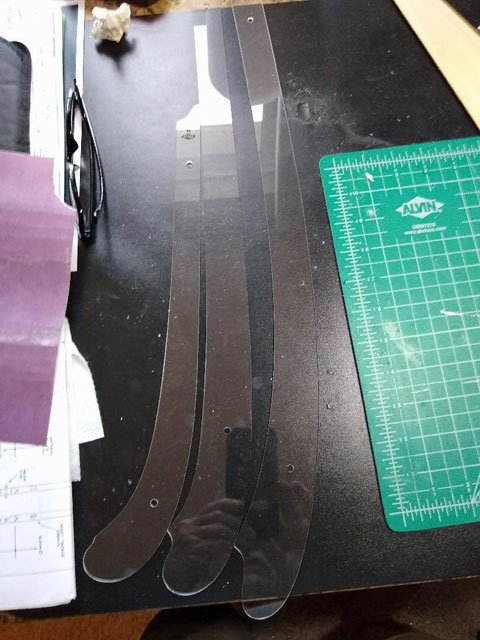
Its yet to see if my approach will work the way I imagine. My mind is busy turning over the order of steps I need to take to complete it. Won't be able to work on the ship till tomorrow so I have time to figure things out. Thanks for your vote of confidence. BTW, the plastic curves I used are Ships Curves, not French Curves.
-
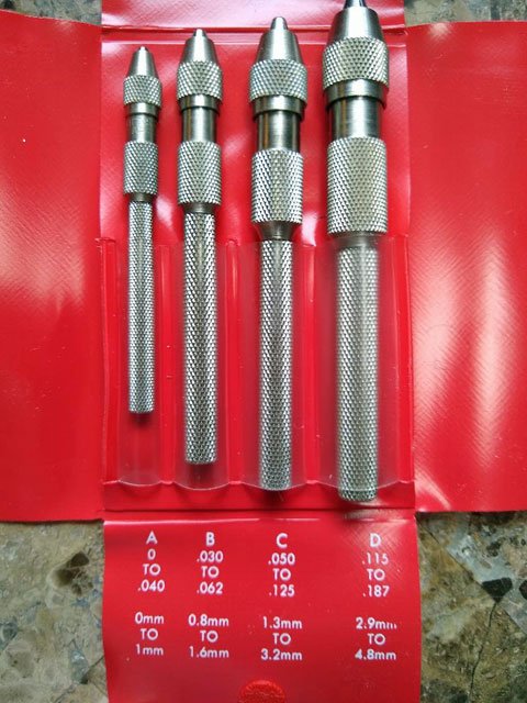
Decided to go with this set of Starrett pin vices. Thanks to all for sharing your advice and suggestions.
-
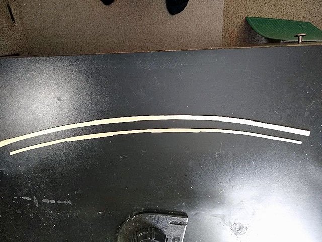
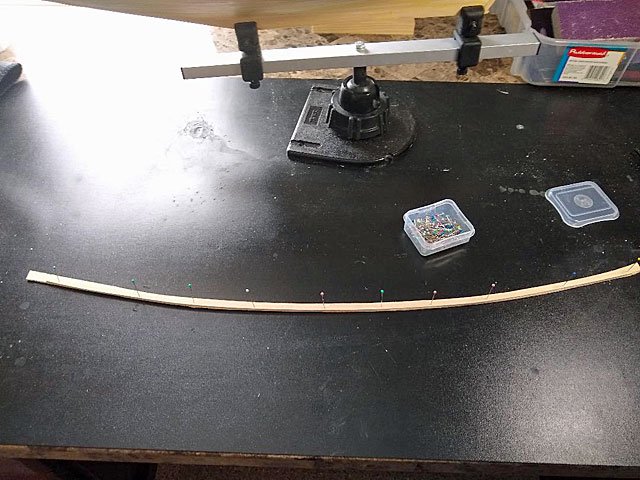
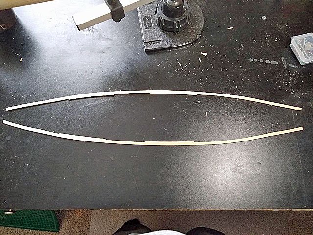
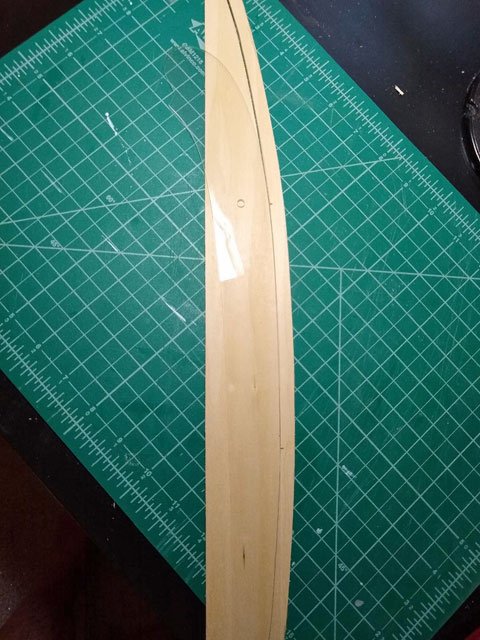
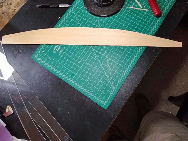
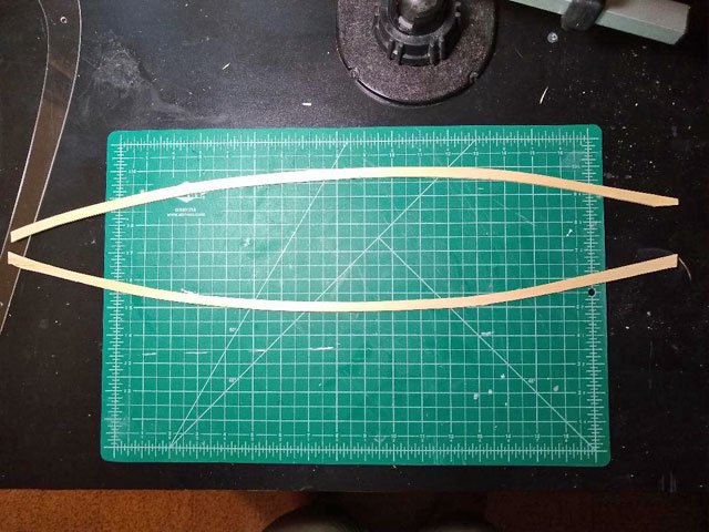
Thanks to all for sharing their method on cutting the top rails. After giving it a good deal of thought, I decided I wanted the top rail to be one piece between the bow and stern pieces. I went to a local hobby shop and purchased a 1/16” X 3” X 24” piece of basswood, about $2.50. Having already trimmed the false frames flush with the top bulwark plank, I laid the new piece of basswood on top of the false frames and, using a mechanical pencil, traced the shape of the hull from underneath. This, I think, was much the same way Tector did his. Then I measured the widest part of the rail on the plans and scribed a line parallel to the one I drew. Using ships curves, I cut out one top rail (tough to see the ship curve as its clear plastic). I then used the cut top rail as a template to draw the second top rail and cut that one out. I now have 2 rough cut top rails. Next will be transferring the measurements from the plans to the rough cut top rails for the wider areas and sanding everything to form the finished pieces. Here is a better picture of the ships curves, I believe there are actually 6 pieces in the set.
- 389 replies
-
- 3
-
-
- bluenose
- model shipways
- (and 1 more)
-
Thanks Richard, that will work! Dave
-
While I haven't posted for some time, the work continues. And I will post some pictures shortly. Right now I'm attempting to install the caprails and have run into an issue. The plans call for the caprail to be made from 7/32 X 1/16 stock. However the parts list for this MS2130 kit does not list such a dimension, nor is there such a dimension in the box. How have you other shipwrights dealt with this issue? Dave
-
I've reached a point I'm my build where I'm going to need a pin vice and bits. I see Micromark has several different styles so I'm looking for advice / suggestions. Dave
-
Nice work Paul! She looks great.
- 168 replies
-
- 1
-
-
- 18th Century Armed Longboat
- Model Shipways
- (and 1 more)
-
Beautiful workmanship!
-
While I'm just finishing up the basic hull, I have managed to obtain a copy of LB Jensons book on Bluenose II. The book is a treasure trove of scale drawings for the entire ship. Including hull planking, rigging, deck housings, sail plan and many details. There are even drawings of below deck areas. What a challenge it would be to build a half open hull showing below decks. Way beyond my current skill level.
- 38 replies
-
- 1
-
-
- bluenose
- model shipways
- (and 1 more)
-
Very nice work. I'm following your build closely as I'm just to the point of painting the waterways and hull.
- 38 replies
-
- 1
-
-
- bluenose
- model shipways
- (and 1 more)
-
Have a extra $100.00 to spend......
CPDDET replied to CPDDET's topic in Modeling tools and Workshop Equipment
Looks like a winner. That one will make the list for a future purchase.