Dr PR
-
Posts
2,401 -
Joined
-
Last visited
Content Type
Profiles
Forums
Gallery
Events
Everything posted by Dr PR
-
 If you have questions about the rigging you might want to look here. I have been puzzling over topsail schooner rigging and have posted some of that I have learned.
 -
How you rig the back stays is another question. Often they were rigged to deadeyes at the aft end of the channels, similar to the shrouds. Sometimes they were rigged as shown in the drawing, but they would interfere with the swing of the boom and mainsail. To get around this the stays were rigged with a gun tackle or luff tackle at the lower end, with the lower block hooked to a ring bolt in the deck close to the bulwark. The back stay on the lee (downwind) side was slacked and unhooked and led forward out of the way of the boom. The windward side stay was tightened to take the strain of the force of the wind on the sail. When the wind shifted (or the vessel maneuvered) the stays were rerigged on the windward side and slacked on the lee side. Same thing on the stays for the fore mast. For more information about schooner rigging and sails see:
-
Don, Curvature along the center line length of the ship at the deck level is called "sheer." Typically the bow is higher than midships, and sometimes the stern is higher than midships. The curve at the deck from side to side is called "camber." A ship's keel was straight when the ship was new, but the bow and stern tended to sag with time, especially on wooden ships. This is because the lift from flotation is proportional to the cross section (side to side) area of the hull. The narrow bow and stern did not have as much lift as the wider midships section. This curvature with drooping bow and stern is called "hogging." If the bow and stern bend upward relative to midships it is called "sagging." Long ships experience some hogging and sagging as they ride over large waves and into the trough between waves.
-
Topsail schooner sail plans and rigging
Dr PR replied to Dr PR's topic in Masting, rigging and sails
Bob, I have seen rigging diagrams and photos of both ways to rig the topping lift. In the drawings the mainsail outhaul ran through a small block attached near the end of the boom and the lift ran through the sheave in the boom. I agree with you that the way with the lift passing through tackle at the mast top makes more sense to me. I have also read at least one account saying the the foot ropes were duplicated port and starboard, and I have seen this arrangement on the Lady Washington replica. They are called "boom horses" on the Lady Washington sail plan. The rope had an eye spliced in the aft end and the two parts ran parallel up to a point inboard of the taffrail where the lines looped over the boom and were spliced. Wooden cleats on the boom held the foot ropes in place. Maybe they are doubled for safety? Maybe it was just easier this way? Here is a photo. To me this is just another example of how there is no one "right way" to rig a ship. Also notice that they used two sheets instead of one riding on a metal horse behind the rudder as on some vessels. And notice the clever way they locked the tiller to the rope- and could easily unlatch it when they wanted the tiller to swing free. The ship was underway and motoring out of harbor against the wind and tide, so this is the operating configuration.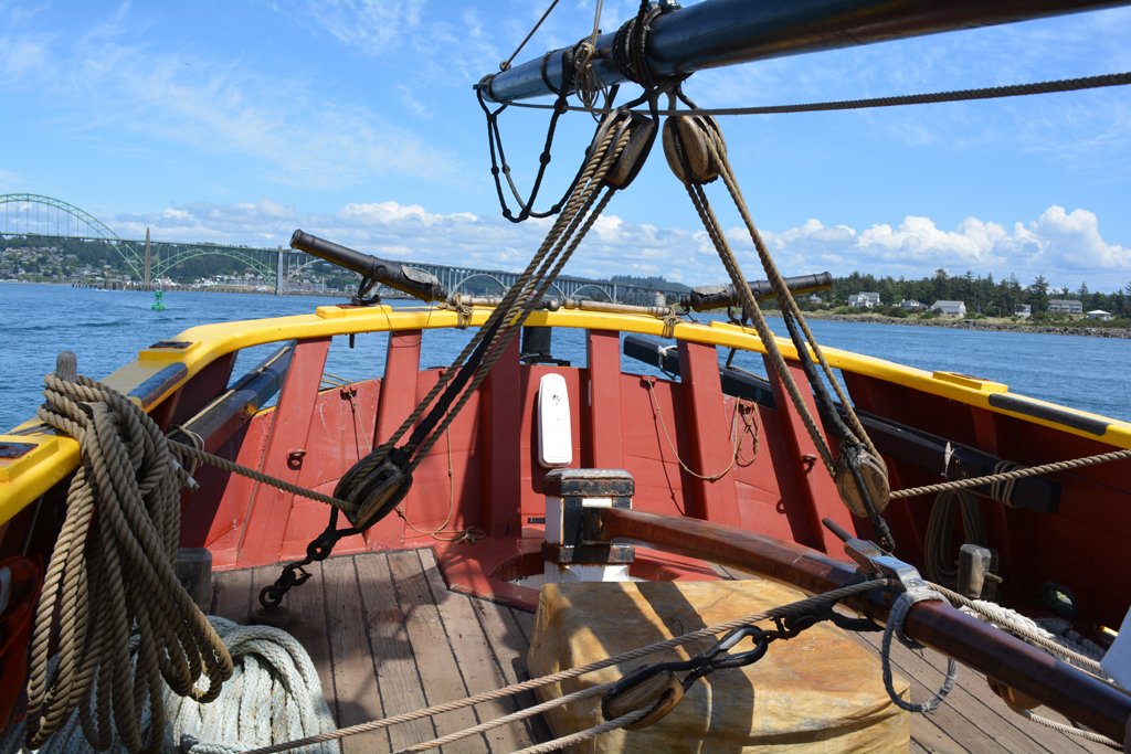
- 104 replies
-
- 4
-

-
- schooner rigging
- Topsail schooner
- (and 1 more)
-
Question regarding the base of the mast
Dr PR replied to DaveBaxt's topic in Masting, rigging and sails
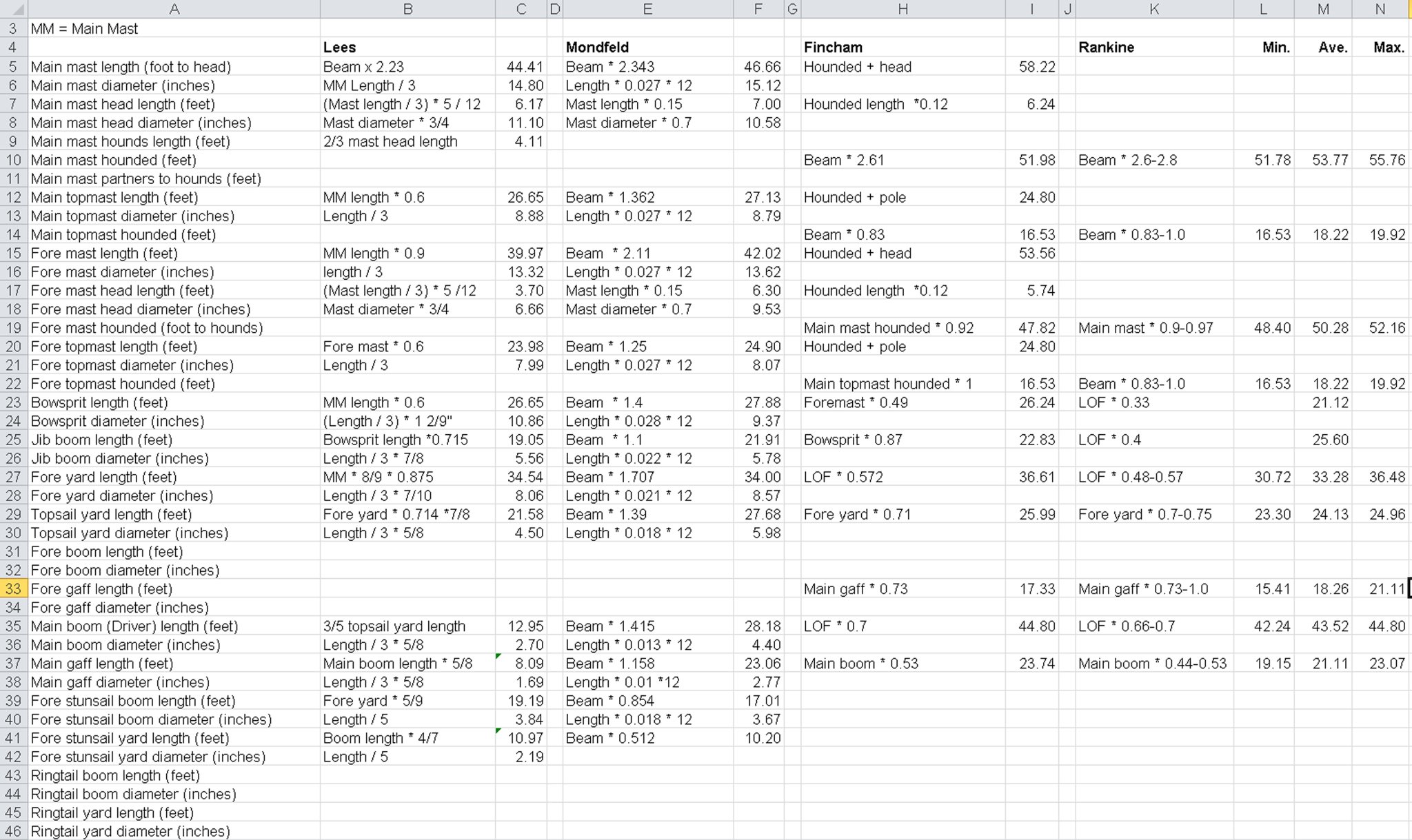
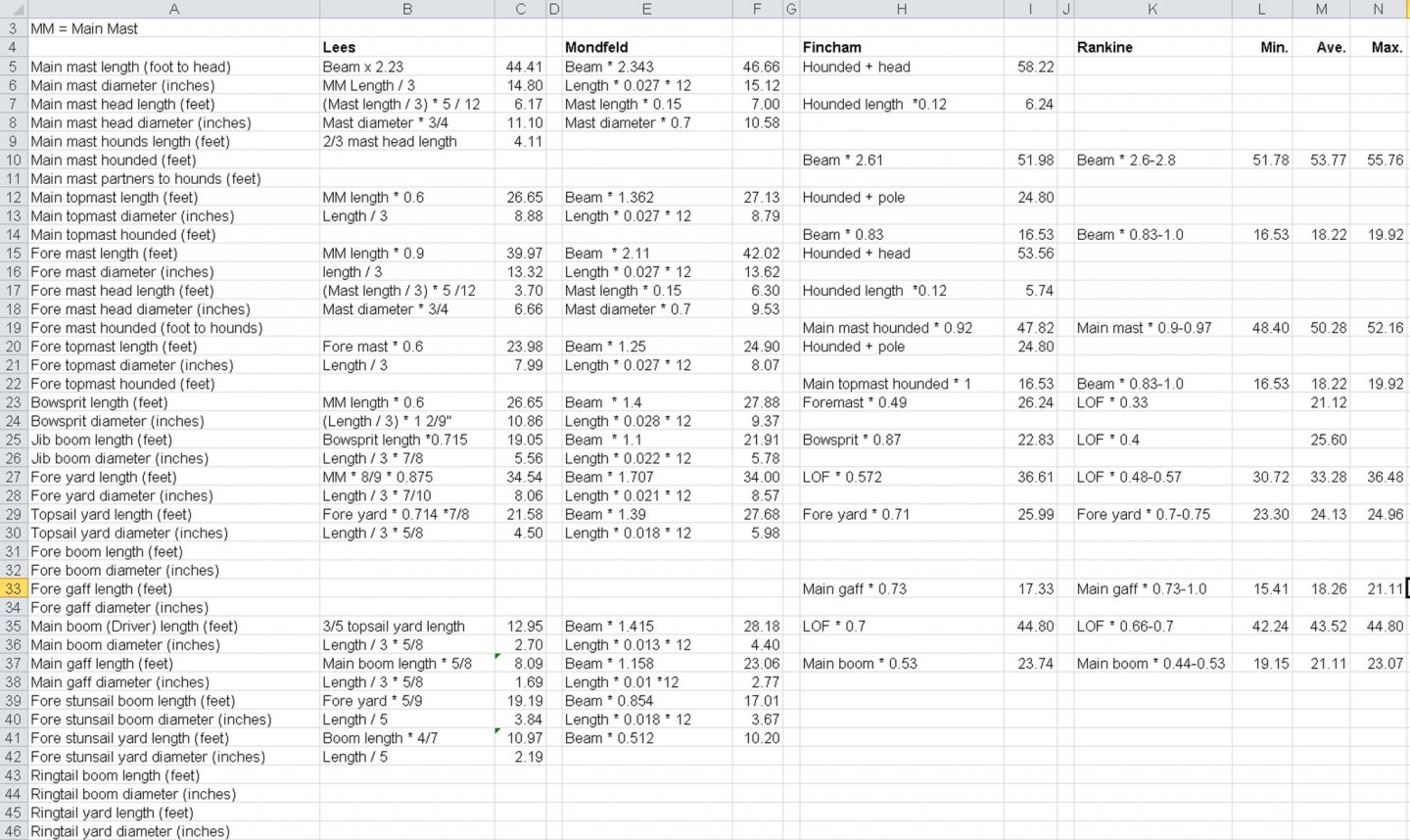
Most ship modeling books recommend against gluing the masts in place. If they aren't at the proper angles you are stuck with it. If the mast fits a bit loose you can correct the angles with the rigging. I visited the Bounty replica used for the Marlon Brando movie but I don't remember a lot about it. It was built oversized to create room for the camera trolleys to move freely along the deck. Somewhere I have a bunch of 35mm slides. Did the masts have any rake (angled back toward the stern) or were they 90 degree vertical from the horizontal? If there is a rake it can be tricky to get the right angle through the wedge ring. I would file out the wedge ring to accept the diameter of the mast rather than trying to reduce the diameter of the mast. Since you are building from a kit you will probably want to use the supplied masts. But if you are really anal about details and want to create your own masts from scratch I have attached an image of a spreadsheet I prepared for my current project (a topsail schooner). It contains the masting rules for ships from Lees and Zu Mondfeld. Ignore the Fincham and Rankine rules - they are for schooners and the masts were much smaller diameter and longer than for square rigged sailing ships. The numbers are for my model of a ship with a 20 foot beam. Just about all the dimensions are based upon the beam of the ship (the widest breadth midships). The mast and spar lengths are in feet and diameters are in inches, and for the real 1:1 scale ships. Just figure out the real dimensions using the Bounty's breadth and divide them by the scale of the model you are building. And if you want to replace the kit thread with scale ropes I have posted spreadsheets for rigging here:
-
Topsail schooner sail plans and rigging
Dr PR replied to Dr PR's topic in Masting, rigging and sails
Here is a spreadsheet for calculating rigging diameters. I have included an Excel 2010 file and a PDF printout. Enter a value for the mast diameter in the green cell and all rigging sizes will be calculated. I label the mast diameter as "Model mast diameter" but you can also enter the real ship mast diameter. Use English (inches) or metric (millimeters) and the resulting calculations will be in the same units. The mast diameter 0.320 inches is for the 1:48 scale topsail schooner model I am working on. CAUTION: The last three calculations for gun carriage rigging are based upon actual cannon bores in inches, and calculated for a 1:48 scale model. You will need to recalculate these for a different scale or if you want to use metric units. All of these values are based upon Lees' formulae. They will work for ships or schooners. Everything is based upon the mast diameter. Rigging calculations.xlsx Rigging calculations.pdf- 104 replies
-
- 3
-
-
- schooner rigging
- Topsail schooner
- (and 1 more)
-
Topsail schooner sail plans and rigging
Dr PR replied to Dr PR's topic in Masting, rigging and sails
Dart, Sorry, I didn't understand your question. "Tack" is the name of the lower fore corner of the sail, and the gear that is attached to handle the sail. It also means changing course. I have photos of ships with the lower corner of the sail (tack) on the windward or leeward sides of the gaff, so they didn't try to raise the sail tack over the peak halliard for the gaff. Either way the sail caught the wind. However, on some schooners with flying topsails (the luff is not attached to the topmast) there is a brail attached to the sail tack and run through a block at the sail peak and back down to the deck. This brail allows the sail tack to be raised over the gaff peak halliard. But for this to work there must be port and starboard tack lines to haul the sail tack down on either side of the gaff and gaff sail. This would be purely a matter of preference for the vessel's captain or owner, and they might change their minds occasionally and try something different. With the American style gaff yard topsail there was no interference between the vertical yard and the mast when tacking. For the European style gaff yard topsail (with the yard more horizontal) they may have lowered the yard when tacking and then raised it again on the lee side. The main idea behind this type of sail was that it could be rigged on deck and then hoisted aloft quickly, and then dropped to the deck again to "furl" the sail. No one had to go aloft. **** I took another look at the drawing of the Russian clipper. It has gaff sails on all three masts! Does this make it a three mast fore and main topsail schooner? It is another good example of the ambiguity in assigning names to individual ship rigs. **** I didn't mean to say that gravity and time alone were responsible for the curvature of the boom, and your 1886 photo of the 1884 schooner shows the curved boom on a relatively new schooner. But gravity would add to the curvature of the long narrow boom, and I would suspect that with time the boom would continue to sag more from the constant influence of gravity. But it looks to me that the primary cause might be the opposing forces of the lift and sheets. One other thing I am trying to understand is the cut of the gaff sail. Why doesn't the sail hold up the center of the boom? Some references say some sails were made with a curvature ("gore") to the foot to increase sail area. From your photo of the Mary G. Powers it looks like the foot of the sail is curved to match the curvature of the boom. So there is no attempt to cut the sail to provide extra lift to the center of the boom.- 104 replies
-
- 2
-
-
- schooner rigging
- Topsail schooner
- (and 1 more)
-
Topsail schooner sail plans and rigging
Dr PR replied to Dr PR's topic in Masting, rigging and sails
Dart, That is a "European style" spar gaff topsail. I described the rigging in an earlier post #16 in this thread for the Main Gaff Topsail. The halliard raises the spar. The tack pulls down to stretch the sail vertically. The sheet spreads the sail horizontally to the end of the gaff. The "American style" typically had the spar oriented almost vertically, but the rigging was the same. It depended upon the cut of the sail. Does this answer your question?- 104 replies
-
- 1
-
-
- schooner rigging
- Topsail schooner
- (and 1 more)
-
Topsail schooner sail plans and rigging
Dr PR replied to Dr PR's topic in Masting, rigging and sails
I think Bob makes a good point. In some cases the topping lift attaches to the aft end of the boom and runs through tackle attached to the mast top and down to the deck. However, in some cases the topping lift is attached to the mast top and runs through a sheave near the aft end of the boom and back to tackle near the mast. In either case the lift pulls up on the boom end. The boom sheets are usually attached to the boom about 2/3 of the boom length (give or take a little) from the mast, and these pull down/in on the boom. With the topping lift supporting (pulling up) the end of the boom and the sheets pulling down closer to the middle of the boom the forces would tend to bend the boom down. Another reason for the curvature would be gravity and time. With the boom supported only at the ends gravity would eventually cause the middle to sag. Schooners typically have lighter mast and spars than larger square riggers, and the main boom on schooners is much longer that typical for the spankers on square riggers. So schooners have long booms of relatively small diameter, and this would allow them to flex more.- 104 replies
-
- 2
-
-
- schooner rigging
- Topsail schooner
- (and 1 more)
-
I have spent weeks looking at rigging rules for ships and schooners. I have created a thread with general discussions of rules for masting and rigging of topsail schooners. It will eventually include the rules for lengths and diameters of all masts, spars, booms and gaffs, plus rules for determining circumference/diameter of all standing and running rigging.
-
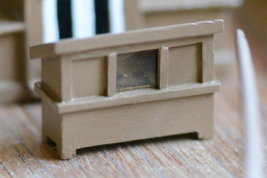
Rachel, Sorry for the late reply. For some reason the Forum no longer notifies me when a post is made to this thread (or any threads I follow). I thought about putting the bell where it is shown on the Albatros drawings, but it would be very susceptible to damage from a swinging boom. I think I will mount it on the fore side of the main mast below the boom foot. This was a common place for a ship's bell. But I haven't decided to do that for certain. The box with the glass front is the binnacle - where the compass was housed. Typically it would have had glass directly in front of the compass rose and opaque doors to either side. Oil lamps would be placed behind the doors on either side of the compass at night to illuminate the compass. The binnacle often was actually a "piece of furniture" that could be moved around, but it was tied down to ring bolts in the deck most of the time. Here is my binnacle. I should put door knobs on the side doors, and tie-down rings on the sides. There is a compass rose behind the window but it doesn't show very well. **** Paul, Some small vessels did not have a capstan or windlass. I have posted a thread about the anchor handling on small vessels. I plan to rig the fish davit, anchor and messengers as in this link:
-
Topsail schooner sail plans and rigging
Dr PR replied to Dr PR's topic in Masting, rigging and sails
George, As long as I am doing this for me I think I should share it with others. After all, others are sharing a wealth of knowledge on this Forum for me to use and enjoy. About Rankine - you just have to appreciate someone who helped develop the Laws of Thermodynamics! James Burke told a story about the development of thermodynamics. The Brits were trying to figure out how to make steam engines work. The Scots were trying to figure out how much heat they needed to distill a gallon of Scotch Whiskey. Does this say something about priorities? And you are right about the research being as interesting as the actual model building. I really enjoy it. I always wanted to understand how all that rigging worked on sailing ships. When I was "building" the CAD model of the USS Oklahoma City CLG-5 I got so sidetracked with the research that it took 14 years to complete. In the meantime I investigated how just about everything on the ship worked and created a web site for the ship! One of these years I will use all of that information to build a real model of the ship.- 104 replies
-
- 3
-
-
- schooner rigging
- Topsail schooner
- (and 1 more)
-
Topsail schooner sail plans and rigging
Dr PR replied to Dr PR's topic in Masting, rigging and sails
George, I have added Cock's and Hedderwick's calculations to the spreadsheet. There are now five values you must add (in the green cells). Mast and spar calculations V2.xlsx I have also added a PDF version of the spreadsheet: Mast and spar dimensions.pdf- 104 replies
-
- 3
-
-
- schooner rigging
- Topsail schooner
- (and 1 more)
-
Topsail schooner sail plans and rigging
Dr PR replied to Dr PR's topic in Masting, rigging and sails
George, I found Cock's formulae gave results similar to Fincham and Rankine. Not exactly the same of course, but in the same ballpark. But his language to describe the rules is about as obtuse as any I have seen. Like many authors he assumes you already know what he means. Fortunately he doesn't just give his rules but he gives numerical values based upon a beam of 20.5 feet. To figure out what he is trying to say you will have to do a lot of calculations to test the many ways in which his instructions can be deciphered relative to the beam width. Hedderwick's rules for schooners (page 361) also approximate Fincham and Rankine. He bases his calculations upon beam, load waterline length, and distance between the deck and keel (housing), compensating for the many different length, width and depth variations in hull designs. His descriptions are very clear despite more complex calculations than the other writers. Both are useful texts for mid 1800s ship design. Thanks again.- 104 replies
-
- 1
-
-
- schooner rigging
- Topsail schooner
- (and 1 more)
-
Topsail schooner sail plans and rigging
Dr PR replied to Dr PR's topic in Masting, rigging and sails
George, Thanks for those references. I guess! Now I'll have to work through all this again - but that's not a problem. I have attached my Excel 2010 spreadsheet for mast and spar calculations (I think). At the top are two green cells that contain the beam and line of flotation values in feet. Be cautious about converting to metric because I did a lot of feet to inches calculations for diameters throughout the page. It could be reworked to use multipliers in each calculation to convert from feet to meters and inches to centimeters - and vice versa. Apparently Fincham was an influential ship designer for the Royal Navy and one of the first to try to standardize ships rigging. There weren't that many people to reference. Professor William John Macquorn Rankine FRSE FRS was quite an influential mathematician who liked to generate mathematical formulae for everything. He reworked Fincham's rules verifying his work with actual ship dimensions. Look him up. He had a very wide range of interests, and was quite influential in many fields. NOTE: THE ORIGINAL SPREADSHEET HAS BEEN UPDATED AND IS AVAILABLE IN A LATER POST.- 104 replies
-
- 1
-
-
- schooner rigging
- Topsail schooner
- (and 1 more)
-
Topsail schooner sail plans and rigging
Dr PR replied to Dr PR's topic in Masting, rigging and sails
I have seen most, or possibly all, of those definitions. As you see the length of the hounds varied from author to author. The problem I had was with the term "hounded length." Most of the authors do not say what part of the hounds are the end of the hounded length. The bottom of the hounds, which could be 1/3 the length of the mast above the partners, the bottom or top of the cheeks, where? Given the plethora of definitions for hounds it seems to me to be anyone's guess. Of course this is obvious to all of the authors, but unfortunately I cannot read their minds. And, being a scientist who knows what it means to know something, I am reluctant to guess. Underhill is the only author I have seen who specifically defines hounded length in unambiguous terms. And as far as I have been able to find Lees doesn't ever say what he means by "mast length" (hounded, measured, what?). -
Topsail schooner sail plans and rigging
Dr PR replied to Dr PR's topic in Masting, rigging and sails
I have been studying rigging dimensions, and that has been an adventure. First, here is a drawing showing various dimensions used for determining mast, spar and rigging diameters. The biggest problem is that many authors use the term "length" ambiguously and just assume you know what they are thinking. This is known as "functional illiteracy" and it is very common. The Hull The length of a sailing ship's hull is often the length on deck - for the uppermost continuous deck from bow to stern. Poop decks, forecastles and gun decks add to the confusion. The line of flotation was the distance at the ship's normal (load) water line between the rabbits in the stem and stern posts. The length between perpendiculars is the distance between the fore peak and the after peak. The fore peak is always the forward most part of the hull at the load water line. This is true for older vessels as well as modern ships. For modern ships the after peak is the after most part of the hull at the load water line. But for wooden sailing vessels the after peak is usually the center of the rudder post at the water line (but not all authors agree on this). The beam is always the broadest part of the hull along its length. Normally it is the absolute widest part of the hull plating or planking unless it is specifically stated as the beam at the waterline. Masts Mast dimensions are even more confusing. The measured length is the total length of the mast timber(s) from the bottom (heel or foot) to the top (cap). This is often used as a reference for calculating other mast and spar dimensions. But it assumes the heel was resting in a step on the keel or keelson (a timber resting on top of the keel timber). But on most models the bottom of the mast stick is some distance above the top of the theoretical keel. This can screw up your calculations if you are not aware of it. The other length that is sometimes used is the hounded length. Take a deep breath, because this gets messy! This is the distance between the mast heel and the mast hounds. And there are just about as many definitions of "hounds" as there are authors. For some authors hounds and cheeks are synonymous, and the cheeks are the pieces on the sides of the mast below the trestletrees in the top. But some say the hounds are supports a third of the length of the mast between the partners (the deck) and the trestletrees. So is the hounded length up to the bottom of the hounds or the top? The authors never say and assume you know. Webster's Third New International Dictionary of the English Language Unabridged, Encyclopedia Britannica, Inc., William Benton Publisher, 1966 (three volumes) says: hounds - the framing at the masthead of a ship for supporting the heel of the topmast and the upper parts of the lower rigging. So the hounds are the top of the cheeks or the trestletrees. Harold Underhill is the only author I have found that specifically states this is the definition he uses. The others leave you guessing. The head is the part of the lower mast from the hounds to the top of the cap at the very top. The measured length is the hounded length plus the head. But hounded length has the same problem for modelers as the measured length. It assumes the mast foot rests on the keel or keelson, and this isn't the case for many models. Some mast dimension tables use the deck to hounds length, and this is a bit more useful for modelers. This is also called the partners to hounds length - the partners are where the mast penetrates the deck - whichever deck is being used for the measurement. And modelers sometimes just use the deck to top length. Whatever measurement you use to determine the mast length, first determine the overall measured length. The measured length (or hounded length) is used to calculate most other mast and spar dimensions, and for mast diameter calculations. Then correct for any distance between the model's keel and the actual mast foot to decide how long your mast sticks should be. Then after you have determined the theoretical main mast diameter from the theoretical measured length (not the corrected model length), multiply it by 4/5 (0.80 or 80%) to get the more probable mast diameter for a schooner. The 4/5 rule comes from Underhill's Masting and Rigging (see references in an earlier post). Got that? Now we can determine the length and diameter of all other masts and spars. Almost everything is based upon the dimensions of the main mast, and that is usually based upon the beam width of the hull. Rigging diameters are calculated from the mast diameters. I have found James Lees' book to be the most complete. Zu Mondfeld's book is almost as complete. But they are both for full rigged square riggers. Howard Chapelle (The Baltimore Clipper) lists actual dimensions of schooners taken off ships in the early 1800s by the Frenchman M. Marestier from ships he inspected. Chapelle also gives masting rules for schooners by John Fincham, a Royal Navy (Great Britain) naval constructor, and Scottish mathematician Professor William Rankine who refined Fincham's rules. Rankine's calculations give minimum, average and maximum dimensions based upon variations in actual ships. I have compiled just about all of these rules in this spreadsheet, using a beam of 20 feet to derive the numbers: EDIT: See later posts for a more inclusive spreadsheet for schooners. If you examine these calculations closely you will see that Lees' and Mondfeld's rules for square riggers give significantly different results than Fincham's and Rankine's schooner dimensions. The Fincham and Rankine rules agree pretty well with the actual dimensions listed by Marestier. Mariestier's data also agrees with Underhill that the schooner masts were significantly lighter (smaller diameter) than given by Lees' and Mondfeld's rules. So this is the basis for the mast and spar dimensions I will be using on my model (as topsail schooner of 20 foot beam). Rigging dimensions will be next.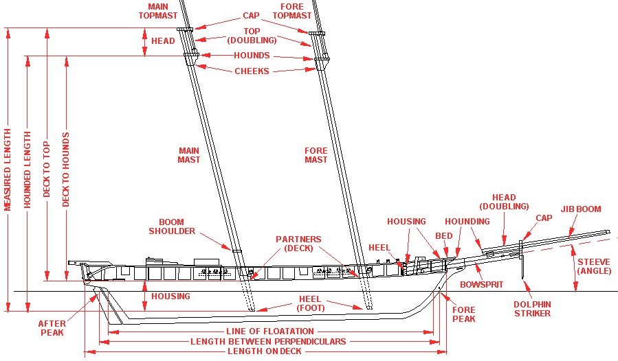
- 104 replies
-
- 5
-
-
- schooner rigging
- Topsail schooner
- (and 1 more)
-
Mike, I am working on a Baltimore clipper also. I am at that start of rigging and have been reading a lot about it. For real ships George Biddlecombe's The Art of Rigging says they started with the bowsprit and then the lower masts. One reason is that the forestay from the fore top usually fastened to the bowsprit and was necessary to support the fore mast. Then the added the jib boom and topmasts. After that went up the spars and booms, and topgallant masts (if any) and spars last. After that the sails were added. But the all around best advice for model building I have ever seen was a lot simpler. Ask yourself if you really want to try to work on spars and sails after the standing rigging is finished? Do you like the thought of trying to rig the sails to the spars through a web of rigging lines? Rig as much as possible to the spars, booms and gaffs on your work bench where you have no obstructions. Rig the spars, booms and gaffs to the lower masts before stepping the top masts. I have been working on the sail plan and rigging for my topsail schooner for a couple of months, and I have posted some general information about schooner rigging here: I have been reading everything I can find about schooner rigging details and rigging sizes and will soon add more to this thread. Almost everything published about rigging has been for square rigged ships, and I have found it to be misleading for rigging schooners. And especially American schooners of the late 1700s and early 1800s because the builders followed their own rules. But after allowing for schooner masts and spars being lighter (about 4/5 the diameter of square riggers the same beam/length) the rules for relative spar and rope sizes can be used as almost everything is related to the diameter of the main mast.
-
Bruma, Harold Underhill's Masting and Rigging the Clipper Ship & Ocean Carrier (Brown, Son and Ferguson, Ltd., Glasgow, 1972) is an excellent source of information about rigging of clipper ships. It is the best written and most complete book on ship rigging I have found. It has detailed descriptions of the masts, bowsprits, yards, booms, gaffs and every line of the rigging, plus a complete pinrail diagram for belaying every line of rigging for a full rigged ship. It says: The down-haul is shackled to the head (peak) of the sail and led down the stay to a block at the foot (tack) , and from there to it's belaying point. The down-haul runs through one or more lizards that are siezed to the hanks at intervals. Not all authors define "lizard" the same, so Underhill says these are short ropes with eyes (thimbles) spliced into one end and the other end siezed to the hanks. The down-haul runs freely through the eyes in the lizard. Hanks are rings around the stay that the sails are siezed to, and allow the sail to ride up and down the stay.. The flying jib downhaul runs through a lead block on the port side of the bowsprit, outboard. The outer jib downhaul runs through a lead block on the port side of the bowsprit, inboard. The inner jib downhaul runs through a lead block on the starboard side of the bowsprit, inboard. The fore topmast staysail downhaul runs through a lead block on the starboard side of the bowsprit, outboard. Underhill shows these downhauls leading to a pin rail in the extreme bow of the ship.
-
Topsail schooner sail plans and rigging
Dr PR replied to Dr PR's topic in Masting, rigging and sails
Peter, Good question!! You are absolutely right. Duh! When I consulted Lever's reference both the jib and fore staysail downhauls were rigged through a single block at the tack and through a few of the "hanks" at the head rope to the peak. This is shown for the fore staysail in Petersson's book but it is not apparent for the jib and flying jib. Biddlecombe also shows the downhauls attached to the peaks of all the fore sails. The tack of each sail is made fast (hooked) to the bottom of the stay, or to the traveler if it is used for the jib. Thanks for pointing out this mistake. Corrected!- 104 replies
-
- 5
-

-
-
- schooner rigging
- Topsail schooner
- (and 1 more)
-
Topsail schooner sail plans and rigging
Dr PR replied to Dr PR's topic in Masting, rigging and sails
Spyglass, The large triangular main sail is sometimes called a "Bermuda rig." Without the high gaff boom the weight topside is lighter, but the sail area is smaller than a gaff sail and a topsail. Did the fore mast have a gaff sail? Or did it have staysails between the masts? If it had a gaff sail it would be a topsail schooner. If it has staysails it might be called a hermaphrodite brig, or brigantine as they are usually called these days. Or maybe a Bermuda brigantine? Chapelle's The Baltimore Clipper shows a picture of a three mast schooner with these peaked sails on all masts. The mizzen or driver sail has a lower boom, but the other two sails are loose-footed. He calls it a "leg of mutton schooner" but modern small boats have a "leg-o-mutton" triangular sail with a clew high above the tack and a boom rigged high on the mast to the clew. Your photos are a good example of the wide variations in sail rigs that have been floated. And you are fortunate to have sailed on her in those waters!- 104 replies
-
- 3
-
-
- schooner rigging
- Topsail schooner
- (and 1 more)
-
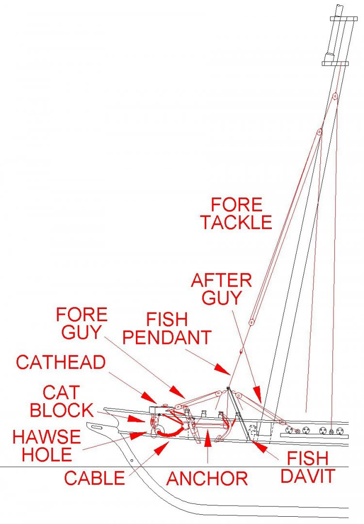
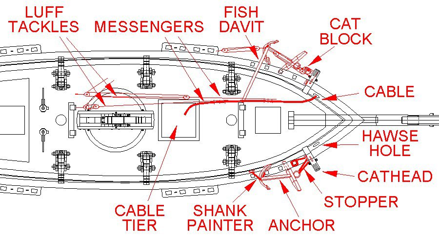
I have been working on a model of a topsail schooner, and had a number of questions about how the anchors were handled. Looking through the literature, and at some of the schooner models on the Forum, it seems that there are several different methods. So which was right for the model I am building? I have a 1980s Mantua Albatros "Goletta Typpica de Baltimora" kit. The kit contains a lot of the "standard" parts the company threw into many kits, regardless of scale and many of these were not well made. When I compare the kit to drawings in Chapelle's The Baltimore Clipper I see a lot of questionable details. The kit includes a capstan, and some topsail schooners used capstans for weighing anchor. But many kits and drawings have windlasses, and some show nothing for handling the anchor. There are other discussions on the Forum about anchor handling in small craft, with lots of opinions. What I present here is a compilation of these discussions and material from several references. What I am interested in is how smaller ships that had no windlass or capstan handled the anchor. Anchor Tackle The anchor tackle on smaller vessels consists of two assemblies used for dropping and raising the anchor. Larger ships may have permanent fish davits and a different arrangement for handling the anchor. Small ships often used a version of what is shown here. The crown or fluke end of the anchor is typically secured to the side of the ship with a shank painter of rope or chain secured to bitts or timberheads to support the fluke end. A stopper rope to support the stock of the anchor is secured to the cathead on one end, looped through the anchor ring and then the free end is looped around a cleat and secured to a timberhead. To drop the anchor the anchor cable is brought up from the cable tier, run through the hawse hole and secured to the ring on the anchor (on some ships the cable is always attached to the anchor ring). Then the cat block and hook are attached to the anchor ring. The fish davit is rigged with it resting on the cap rail and the inboard end resting against some firm object like the mast or knight head. The davit may be positioned over the anchor flukes using fore and after guys. The fish pendant runs over a sheave in the end of the fish davit. It has a large fish hook on the lower end and the upper end is tied around a thimble. The fore tackle is hooked into the thimble and provides the lifting force to raise and lower the anchor. I have also seen drawings where the fish tackle was rigged to the fore course spar and a fish davit was not used. With the fish pendant and cat tackle pulled tight the shank painter securing the anchor to the ship is removed. The anchor is then lowered along the ship's side with the fore tackle and fish pendant until it is hanging beneath the cathead on the cat tackle. Then the fish hook is unhooked and taken in. The cat tackle is slacked to allow the stopper to carry the weight of the anchor, and then the tackle is tied back to clear the anchor. To drop the anchor the stopper is released from the timberhead and allowed to slip over the cleat, allowing the anchor to fall. To weigh (raise) the anchor the anchor cable is hauled in using tackles (smaller vessels), a windless or a capstan and messenger line (larger ships). Smaller schooners often did not have a capstan or windlass so one or two luff tackles were used to pull a messenger line that was lashed to the anchor cable. If one tackle was used when it became two blocked (both blocks come together) the anchor cable was secured to the bitts and the messenger was run out again and tied to the cable. When two tackles were used and one tackle was two blocked the other tackle was tied to the cable to continue pulling while the first was run out again. The messenger line might be a loop with one side tied to the anchor cable to haul it in and the other returning forward. When the anchor broke the surface the cat hook was attached to the anchor ring. Then the anchor was “catted” by raising it to the cathead with the cat tackle. The fish davit and pendant were rigged and the fish hook was hooked to the anchor stock at the flukes. The anchor was “fished” using the fore tackle to hoist the flukes up to the cap rail where the shank painter ropes or chains were passed around the anchor and secured to timber heads or cleats to support the anchor. Then the fish pendant was unhooked. A wooden fender or "shoe" was placed between the anchor flukes and the side of the ship to protect the hull as the anchor was being fished. On some ships the anchor head remained suspended by the cat tackle. On other vessels the head of the anchor was secured with stopper lines to cleats or timberheads. The cat tackle was usually left hooked to the anchor ring. The anchor cable may have been removed and stowed in the cable tier. One reference said two hefty seamen could hoist a relatively light anchor with a simple tackle. By increasing the number of sheaves in the tackle greater lifting power could be achieved, but at the expense of having to pull more line through the tackle and a much slower process. But with heavier anchors this system was not practical. Instead of the luff tackles a capstan could be used to pull a messenger loop wound around the capstan and running around the fore deck and back to the capstan. The messenger was tied to the anchor cable and hauled back until the lashings reached the cable tier. Then new lashings would be tied around the cable and messenger up forward and the hauling would be continued until the anchor was catted. With a windlass on the fo'c'sle the anchor cable would be wound around the barrel or warping drum. For dropping the anchor the winch would be allowed to rotate freely. When weighing the anchor the windlass ratchet mechanism would allow men with poles to turn the barrel to haul in the cable. The cable could be secured with stopper lines to bitts. One other detail I came across is that the anchor might be hauled inboard after the cable was detached and stored below decks in the cable tier. Here are a couple of useful references: The Young Sea Officer's Sheet Anchor by Darcy Lever in 1808 (reprinted by Algrove Publishing Ltd., Ottowa, Ontario, Canada, 2000) tells the novice officer or seaman how to rig a ship - every detail of how to put all the pieces of the masts and rigging together. It is essentially an illustrated glossary of nautical terms and a how-to book. It has a discussion of anchors and anchor handling. The Art of Rigging by George Biddlecombe in 1925 (reprinted by Echo Point Books & Media, LLC., Brattleboro, Vermont, USA, 2016) is based upon David Steel's 1794 The Elements and Practice of Rigging and Seamanship. It has an excellent glossary and many illustrations. I think you can find Steel's original book on line as a PDF file.
- 24 replies
-
- 5
-
-
- anchor handling
- schooner
- (and 1 more)
-
Topsail schooner sail plans and rigging
Dr PR replied to Dr PR's topic in Masting, rigging and sails
Bruce and George, You beat me to it! Here are the most useful references I have found so far for topsail schooners. 1. To me the most important reference is Howard Chapelle's The Baltimore Clipper (Edward M. Sweetman Co., New York, USA, 1968). It has a lot of information about the development of topsail schooners and lots of drawings and illustrations. More importantly, it lists the dimensions of actual vessels in the early 1800s. It has many sail plan drawings, but says little about the rigging. 2. The Global Schooner by Karl Heinz Marquardt, Naval Institute Press, Annapolis, Maryland, USA, published by Conway Maritime Press, London, 2003. This book is devoted to the history and construction of schooners. It has an exhaustive history of the schooner rig - the best I have seen. The book has very detailed chapters on masts and rigging with detailed drawings. Numerous tables in the appendices give rules and dimensions for mast, spars and rigging. It is the most complete text on schooner rigging that I have found. It is a large book (11.6 x 10 inches, 294 x 254 mm) with 239 pages containing many detailed drawings, full page ship plans and illustrations. 3. Lennarth Petterson's Rigging Fore-and-Aft Craft (Naval Institute Press, Annapolis, Maryland, USA, 2015) has a section on topsail schooners, and most of this also applies to straight fore-and-aft schooners. He has drawings showing just about every possible line you could have on a schooner, but it is doubtful if any one ship carried all of the rigging he shows. 4. Howard Chapelle's The American Fishing Schooners 1825-1935 (W. W. Norton & Company, New York and London, 1973, 690 pages) is a must if you are interested in these schooners. It gives the history of these ships. However, it has a 371 page "Notebook" with very detailed drawings and descriptions of just about every part of schooner structure and rigging, and much of it applies to all schooners. 5. John Leather's The Gaff Rig Handbook (Wooden Boat Books, Brooklyn, Maine, USA, 2001) gives a lot of detail for rigging modern fore-and-aft yachts and racing boats, but much of this isn't very useful for 19th century and earlier vessels. However, he does give the history of the development of different types of rigs, mainly focusing on British vessels. But the book doesn't have a useful index and finding information about a particular rigging detail is like looking for a needle in a haystack. 6. Harold Underhill's Sailing Ship Rigs and Rigging (Brown, Son & Ferguson, Glasgow, Scotland, 1969) has general sail plans for many types of ships and boats but not much about the actual rigging. But it does have a useful glossary. 7. An excellent reference for the development of fast sailing ships is Howard Chapelle's The Search for Speed Under Sail (W. W. Norton & Company, New York, USA, and London, Great Britain, 1967). It has some sail plans for schooners and a few rigging diagrams. 8. I also have Underhill's Masting and Rigging the Clipper Ship and Oceanic Carrier (Brown, Son & Ferguson, Glasgow, Scotland, 1972). It is an excellent book with a tremendous amount of detail about sails and rigging. It is mostly for British clipper ships, but it has a section on schooners. Unfortunately the drawings seem to be scattered randomly through the book and are rarely anywhere near the text that refers to them. But it does have a list of drawings after the table of contents. Most of what he writes about are rigs of the last half of the 19th century and early 20th century. If you are interested in clipper ships this is a must have! It has perhaps the best and most inclusive index of any book I have seen, with links to descriptions of every part of the ship. 9. James Lees' The Masting and Rigging of English Ships of War 1625 - 1860 (Naval Institute Press, Annapolis, Maryland, USA, 1990) is almost entirely about larger square riggers. However it does give a lot of detail about parts of rigging that does apply to schooners. More importantly, it tells how to determine the dimensions of spars, rigging, blocks and such based upon the mast diameter, and has lots of tables. But some caution is necessary because fore-and-aft rigs are much lighter than square rigs, and mast diameters are usually smaller for schooners. And the text can be confusing because he often fails to explain exactly what dimensions he is referring to. Mast and spar dimensions are usually diameters but rope dimensions are circumferences. Divide by PI (3.14159) to get the rope diameter. The biggest problem I have had is all the nautical jargon these authors use, usually without any glossary. And different authors use different arcane terms for the same things. Some authors think a work cannot be scholarly unless it is written so an ordinary person cannot understand it, and use "five dollar words" where a "nickle" word would do just as well. I have found three books indispensable for translating the nautical jargon into meaningful explanations: 10. The Young Sea Officer's Sheet Anchor by Darcy Lever in 1808 (reprinted by Algrove Publishing Ltd., Ottowa, Ontario, Canada, 2000) tells the novice officer or seaman how to rig a ship - every detail of how to put all the pieces of the masts and rigging together. It is essentially an illustrated glossary of nautical terms and a how-to book. But there isn't a lot about fore-and-aft rigs. 11. The Art of Rigging by George Biddlecombe in 1925 (reprinted by Echo Point Books & Media, LLC., Brattleboro, Vermont, USA, 2016) is based upon David Steel's 1794 The Elements and Practice of Rigging and Seamanship. It has an excellent glossary and many illustrations. Again, not much about schooners. I think you can find Steel's original book on line as a PDF file. 12. A good general reference is Wolfram zu Mondfeld's Historic Ship Models (Sterling Publishing Co., Inc., New York, USA, 1989) although it is oriented to square rigged ships and doesn't have much to say about schooners. But it has a tremendous amount of detail about all parts of wooden ships and a lot of the history of different configurations. It has lots of diagrams and text describing the parts of ships' hulls, rigging, sails and such. The book has tables for figuring the dimensions of mast and spars. It is one of the best references for sailing ship modelers. 13. William Falconer's Universal Dictionary of the Marine, 1769, is very useful for understanding the arcane and obsolete terminology used in many texts, especially the older works. You can find this book in PDF format on line.- 104 replies
-
- 6
-
-
-
- schooner rigging
- Topsail schooner
- (and 1 more)
-
Topsail schooner sail plans and rigging
Dr PR replied to Dr PR's topic in Masting, rigging and sails
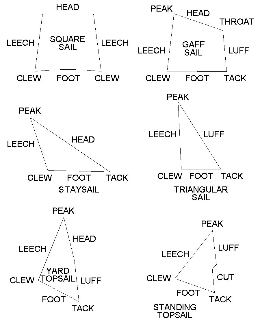
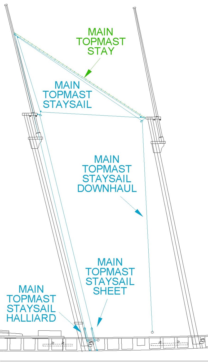
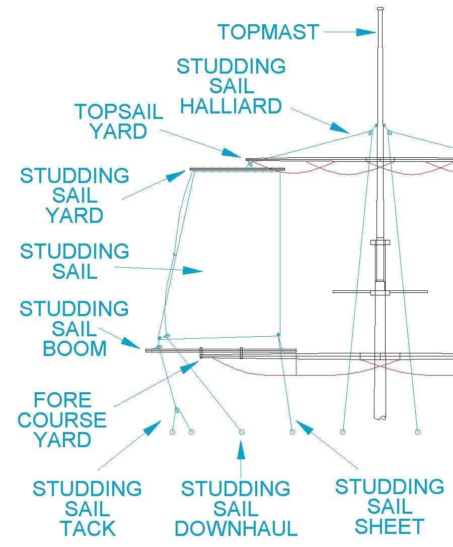
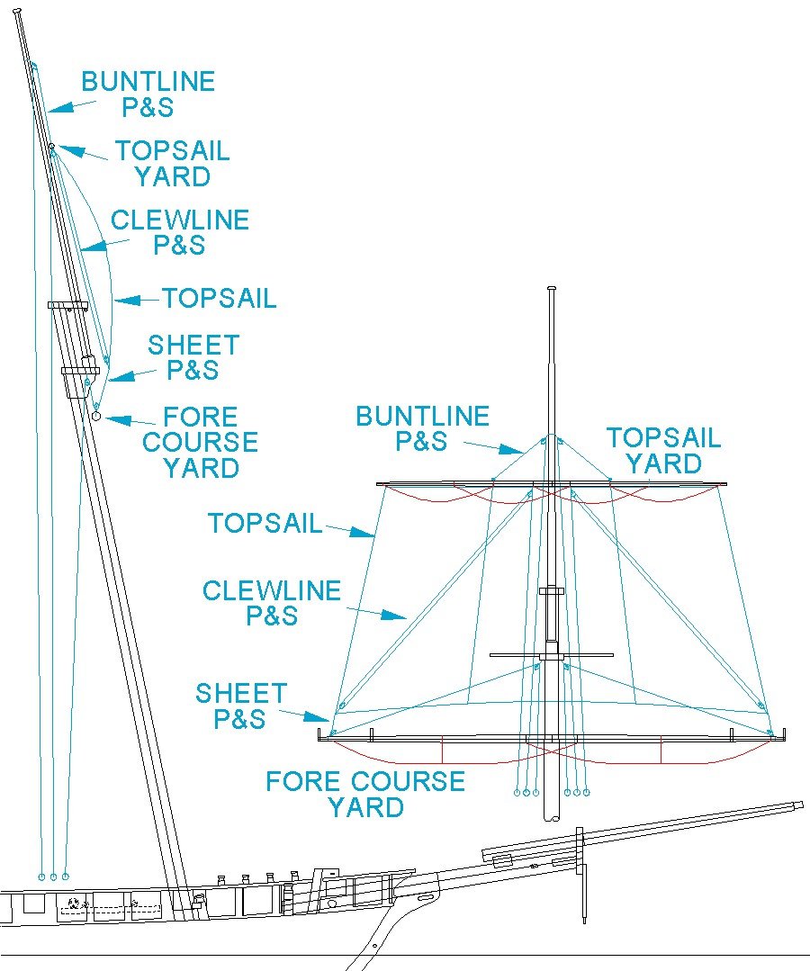
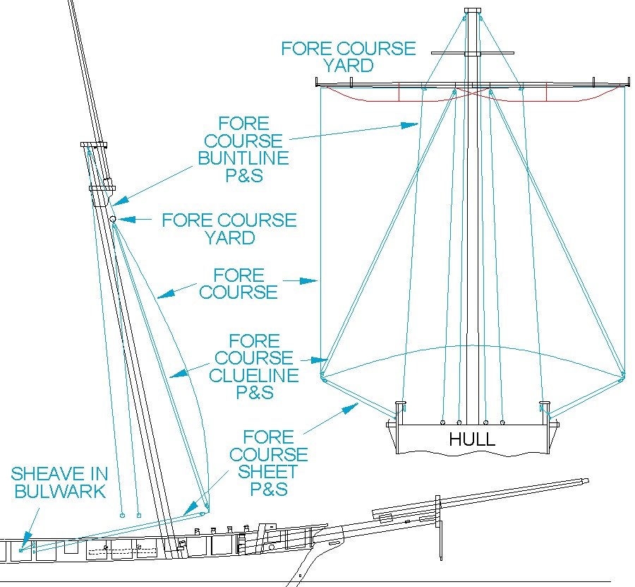
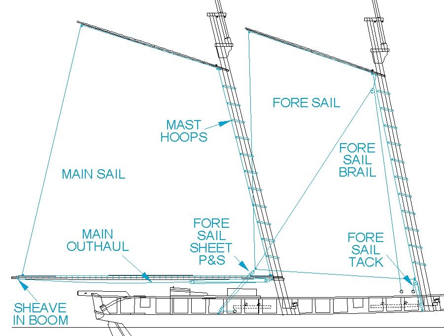
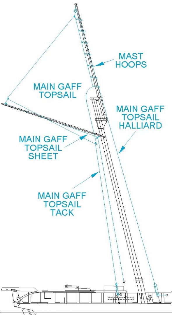
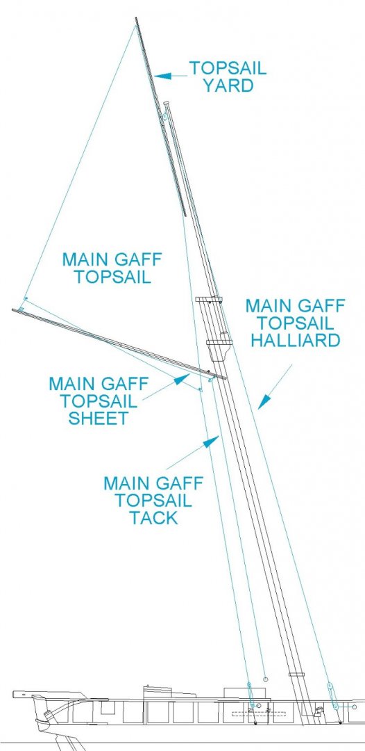
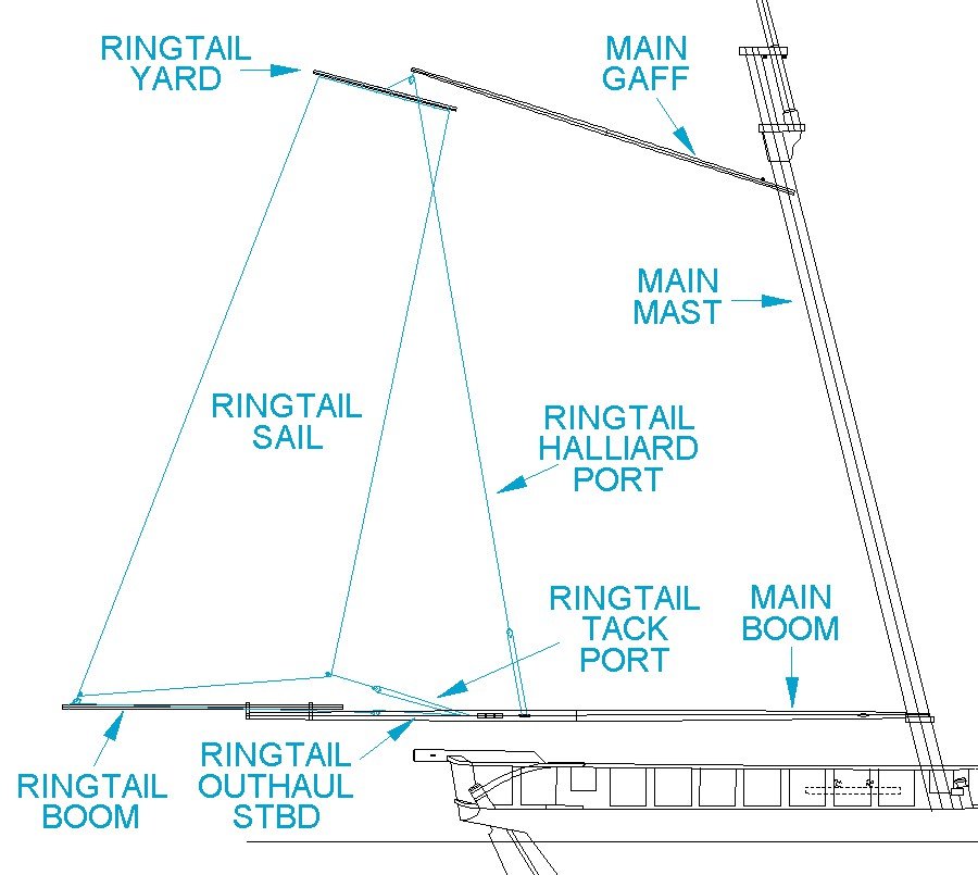
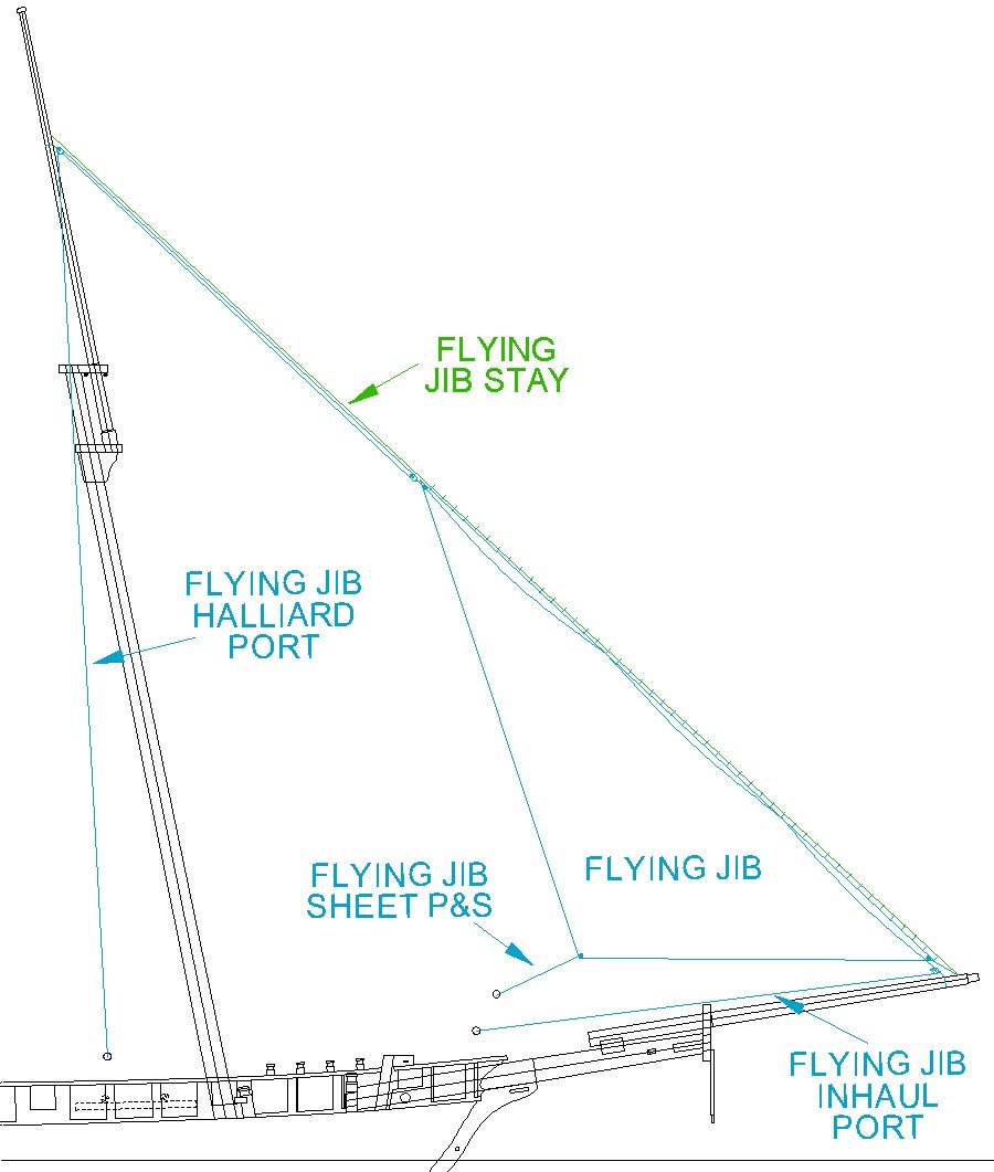
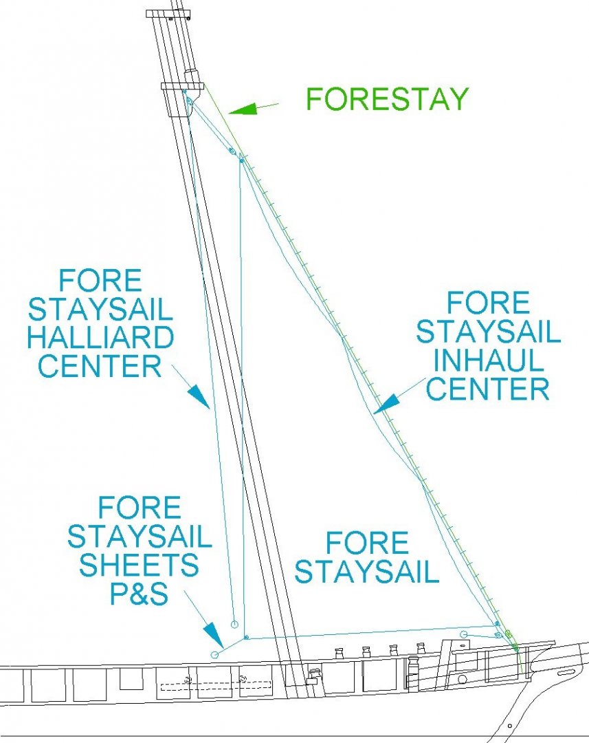
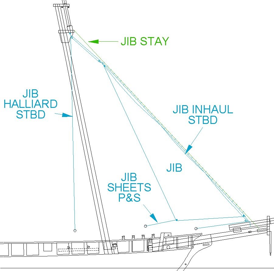
Sail Rigging The diagram shows the parts of the common types of sails. The leech is the after or outboard edge of a sail. It is normally free (unattached). The luff is the forward part of fore-and-aft sails. The luff is often attached to a mast or stay. Some authors refer to the luff as the "fore leech" and the leech as the "after leech." The square sail, gaff sail and yard topsail are four sided sails with a head and a foot. The head is laced to a spar or boom. Triangular sails (foresails and staysails) have the luff attached to stays, although this side is sometimes called a head on staysails. Sometimes the side of the sail that attaches to the stay is called the stay. The foot is usually free or unattached; although gaff sails often have the foot laced to a boom. Sails that have the foot free are called loose-footed. The peak (or peek)is the highest part of a sail, although the highest parts of a square sail are just called the head. Halliards that are used to raise the sail are attached to the peak. The clew is the lower corners of a square sail, and the aft corners of fore-and-aft sails. The sheets are attached to the clews to control the loose parts of the sail. The tack is the corner of a fore-and-aft sail opposite the clew along the foot. It is usually positioned close to a mast or bowsprit. Tack lines or downhauls are attached to the tack to pull down on the sail to tighten it or lower it. Roach and gore are two terms you will come across in discussions of sails. Roach is a curved edge to a sail. It allows the sail to curve outward. The leech of gaff sails and triangular sails, may have an outward roach curve to increase the area of the sail. The foot of square sails and gaff sails may be curved outward or "bellied." However, the foot of square sails may be roached upward to create an arc that rises over stays or other rigging. I am not sure all authors agree that the upward curve of a square sail foot is a roach, and they may have another term for it. Gore is a term applied to sails that are wider at the foot than at the top, as in the square sail illustration above. Gore is accomplished by adding triangular cloths to the outer edges to expand the foot of the sail. Flying Jib or Outer Jib The flying jib or outer jib is the foremost of the foresails, although not all vessels carried one. If the sail is "flying" (not attached to a stay) it is supported only by the halliard at the peak and the downhaul at the tack. Often the outer jib is laced on the forward or luff side to a stay with many hanks (loops of small rope). The stay may be called the flying jib stay, the topgallant mast stay, the royal stay, or outer jib stay, depending upon how the ship is rigged. If the vessel has a flying jib boom the stay is attached at the forward end of the flying jib boom, otherwise it is at the forward end of the jib boom as shown in the drawing. Many modern schooners have a single long bowsprit with the stays attached at more or less even spacing along the spar. The flying jib halliard is rigged with a gun tackle attached to the fore topmast and the peak of the sail. It hoists the forward side of the sail up the stay. The lower end of the halliard is often fastened to a pinrail, either at the base of the mast or on a bulwark. The flying jib inhaul is attached to the peak and leads down through a few hanks on the head rope to a single block attached to the jib boom at the stay. From there it runs back to the bow. It is used to pull the sail down when reefing. Port and starboard flying jib sheets are attached to the clew. The sheets and inhaul are attached to pins or cleats in the bow. When the vessel changes course or the wind shifts the windward sheet is loosened, the clew is pulled over the jib stay, and the leeward (downwind) sheet is tightened to control the loose corner of the sail. The flying jib sail can be small or large, depending upon the vessel. It can be positioned anywhere along the supporting stay, and a smaller sail may be hauled high to the topmast so it flies above the other foresails. The sail tack is hooked to the boom near the stay. If the stay leads to the end of the jib boom or flying jib boom, the tack may fasten to a traveller (free moving ring around the boom) and the inhaul through a block on the traveller and back to the bow. The inhaul pulls the traveller aft to so the sail can be furled. An outhaul runs through a sheve in the fore end of the jib boom and back to the bow. The outhaul pulls the traveller to the end of the boom to set the sail. However, depending upon how the stay is rigged, the stay may run through a sheve on the traveller and out to a sheve at the end of the boom. From there it leads back to the bow. With this rig there is no separate outhaul. The stay is loosened to allow the inhaul to pull the traveller aft, and the stay is pulled taut to haul the traveller back forward to the end of the boom. Jib The jib is another of the foresails. The forward edge is attached to a jib stay that normally leads down from the foremast top to a point at the end of the jib boom or to attachments just aft of the bowsprit cap as shown in the drawing. The jib halliard attaches at the peak through a gun tackle attached to the fore top. The fall leads down to the deck. The halliard hauls the sail up the say. The tack is hooked to the jib boom near the stay. If the jib stay leads to the end of the jib boom, the tack may fasten to a traveller as described for the flying jib or outer jib. The jib inhaul fastens to the jib peak and runs through a few hanks on the head rope to a block on the bowsprit bees (or a sheave at the end of the jib boom or traveller), and back to a belaying point in the bow. The inhaul pulls the sail down along the stay for reefing. When the vessel changes course or the wind shifts the windward jib sheet is loosened, the clew is pulled over the fore stay, and the leeward (downwind) sheet is tightened to control the loose corner of the sail. Some larger vessels have an inner jib, outer jib or fore topmast staysail rigged between the flying jib and jib. As many as five triangular fore sails were flown on the largest fore-and-aft rigged vessels. This sail may be four sided, with a short head stick at the peak. The short top edge is lashed to the head stick. The head stick has holes at the ends. A short head rope attaches at each end to an end of the head stick, and has a thimble or eye spliced in the middle. The halliard tackle attaches to the thimble. Fore Staysail The fore staysail is the aftermost of the fore sails. The leading (luff) edge is laced around the forestay. The fore staysail halliard attaches at the peak through a gun tackle attached to the fore top. The fall leads down to a point on deck near the base of the mast. The tack is hooked to a point in the bow near the forestay. The fore staysail inhaul is attached to the peak of the sail and leads down through a few hanks on the head rope to a single block attached to a point near the base of the forestay and runs back to a belaying point in the bow. It is used to haul the sail down for reefing. The clew has port and starboard fore staysail sheets attached. The sheets are attached to pinrails or cleats on the bulwarks. When the vessel changes course or the wind shifts the windward sheet is loosened, the clew is pulled around the foremast, and the leeward (downwind) sheet is tightened to control the loose corner of the sail. On some vessels there is only one fore staysail sheet. It is attached to a traveller riding on a "horse" or bar running transverse (port to starboard) slightly above the deck in front of the fore mast. As the ship changes course, or the wind direction shifts, the clew of the sail blows to the downwind side. This sail may have a head stick as described for the jib. Topsail The topsail is bent to the topsail yard. The topsail sheets (port and starboard) are attached to the clews of the sail and run through single blocks attached near the ends of the fore course yard. From there the sheets lead to single blocks fastened to the fore mast top and from there down to points on deck near the base of the fore mast. The sheets pull the clews down to stretch the sail between the topsail yard and the fore course yard. The standing parts of the port and starboard topsail clew lines are fastened to the strop eye of single blocks that are fastened to the topsail yard near the center. The running part of the clew line runs through a second single block attached to the clew of the sail, and from there back through the first single block at the topsail yard. Then the falls lead down to the deck near the base of the fore mast. The clew lines hauled up the clews of the sail when it was being reefed. They could also be used to haul down the topsail yard to the fore course yard when the topsail yard halliard was loosened. The port and starboard topsail buntlines were used on some vessels. They were attached to the foot of the sail and ran up through eyes on the topsail yard, and from there to single blocks attached to the topmast above the yard. From there the buntlines ran down to the deck near the base of the foremast. The buntlines were used to haul up the foot of the sail when it was being reefed. Fore Course The fore course was a loose footed square sail flown below the fore course yard. It was not normally flown on topsail schooners, and was deployed to increase speed when running with the wind from astern. When not in use the sail and rigging were stowed below. However, on some schooners the course was more or less permanently rigged and reefed to the fore course yard as it would be on a square rigger. The fore course head is bent to the fore course yard. The fore course sheets (port and starboard) runs through a single block attached to the clews of the sail. The standing parts lead to ring bolts on the outboard side of the bulwarks. The running parts of the sheets lead through sheaves set into the bulwarks aft of the fore mast and tied off to cleats on the inboard sides of the bulwarks. The sheets pull the sail down from the fore course yard. A separate short boom attached to the bulwark was used sometimes to pull the windward clew of the sail outboard to catch more wind. The standing parts of the port and starboard fore course clew lines are fastened to the strop eye of single blocks that are attached to the fore course yard near the center. The running parts of the clew lines run through a second single block attached to the clew of the sail, and from there back through the first single block at the fore course yard. Then the falls lead down to the deck near the base of the fore mast. The clew lines hauled up the clews of the sail when it was being reefed. The port and starboard fore course buntlines were attached to the foot of the sail and ran up through single blocks attached to the fore course yard, and from there to single blocks attached to the fore top cap above the yard. From there the buntlines ran down to the deck near the base of the foremast. The buntlines were used to haul up the foot of the sail when it was being reefed. Foresail The fore sail head was bent to the fore gaff. The luff was attached to the fore mast with rope loops or lacing, or with hoops that were free to ride up and down on the mast. The throat of the sail was fastened to a ring bolt on the jaws of the gaff and the peak was fastened to the end of the gaff. The sail was raised and lowered with the fore gaff peak halliard and fore gaff throat halliard. If the sail was “loose-footed” without a boom the fore sail tack was attached to the double block of a luff tackle. The single block was fastened to the deck and the fall was tied to a pin, cleat or bitt at the base of the mast. If the sail had a boom it was rigged as described for the main sail. The port and starboard fore sail sheets had gun tackles with the running blocks hooked to the sail clews. The standing blocks were hooked to ring bolts on deck near the bulwarks, and the falls were tied to cleats or pins on the bulwarks. When the vessel changed course, or the wind shifted, the windward sheet was slacked (or unhooked), the sail clew was pulled around the mast to the leeward side, and the lee sheet was pulled tight to stretch the sail. Some vessels had a single sheet attached to a traveller on a horse as described for the fore staysail. The sail may have had a fore sail brail if it was loose footed. The brail is attached to the clew and leads up through a single block on a pendant attached to the gaff jaws. From there the fall runs down to the deck. The brail is used to haul up the clew to clear the main stay. The clew is pulled over the main stay and the lee sheet is hooked to the clew and drawn tight as the brail is slacked to extend the sail again on the lee side. The brail was also used to loosely furl the sail close to the mast. Main Sail The head of the main sail was bent to the main gaff. The luff was attached to the main mast with hoops that were free to ride up and down on the mast or rope loops or lacing. The throat of the sail was fastened to a ring bolt in the jaws of the gaff and the peak was fastened to the end of the gaff. The sail was raised and lowered with the main gaff peak halliard and main gaff throat halliard. The foot of the sail usually was bent to the main boom, although some vessels had a loose footed sail secured only at the clew and tack. The tack was attached to a ring bolt in the boom jaws. The main outhaul was attached to the clew and ran through a sheave set into the boom near the end (or possibly a single block attached near the end of the boom). The outhaul lead forward to a luff tackle with the double block hooked to a ring bolt at the boom jaws. The fall was tied to a cleat on the boom. The main outhaul pulled the foot of the sail tight along the main boom. Main Topmast Staysail Some ships carried a main topmast staysail while others used a fore gaff topsail. The gaff topsails were rigged like the main gaff topsails described below. The main topmast staysail luff or head was loosely tied to the main topmast stay so the sail could ride up and down on the stay. The main topmast staysail halliard attached to the peak and lead through a single block attached to the main topmast at the stay. From there it lead down to a luff tackle attached to the deck near the base of the main mast. The fall was tied to a pin or cleat on the bulwark. The halliard pulled the peak of the sail up the stay to spread the sail. The main topmast staysail sheet attached to the clew and ran through a single block fastened to the main top cap. From there it lead down to a luff tackle attached to the deck near the base of the main mast. The fall was tied to a pin or cleat on the bulwark. The sheet pulled the sail clew down to spread the sail. It was loosened when the sail was reefed. The main topmast staysail downhaul was attached to the peak and lead down through a single block attached to the fore mast top cap. From there it lead down to the deck. The downhaul was used to pull the peak of the sail down the stay to reef the staysail. Fore Gaff Topsail A ship may have a fore gaff topsail instead of the main topmast staysail. It was rigged like the main gaff topsail. Main Gaff Topsail There are three common configurations for this sail (but seven or eight possible configurations). Standing Gaff Topsail The standing gaff topsail luff is fastened to the top mast with hoops. The sail usually has a cut to clear the main mast top. The main gaff topsail halliard from the peak runs through a single block tied to the mast top or a sheave set into the mast and down to a tackle hooked to a ring bolt on deck. The halliard pulled the peak of sail up the topmast to spread the sail. The main gaff topsail sheet runs from the clew through a single block at the end of the main gaff or a sheave set into the end of the gaff. From there it runs to a single block attached to the gaff jaws and down to the deck. It is used to spread the foot of the sail along the gaff. The main gaff topsail tack line leads down to a tackle hooked to a ring bolt on deck. The tack line pulls down on the tack to stretch the sail. A brail (not shown) is sometimes attached to the tack of the flying gaff topsail, run through a single block at the peak and back to the deck. It is used to raise the tack over the gaff peak halliards when changing course, and then the tack is drawn down again. In this case there would be port and starboard tacks. The lee tack would be pulled taut to stretch the sail while the windward tack would be loose and ride over the peak halliard. In some cases a brail was attached to the center of the sail luff or the lowest mast hoop. From there it ran down through a single block at the tack, out through cringles on the foot of the sail to a single block at the clew, up through cringles on the leech of the sail to a single block at the peak, and the fall lead down to the deck. This allowed the sail to be furled (drawn into a bunch) quickly from the deck. A gaff topsail clew line (not shown) may be attached to the gaff jaws, run through the clew cringle, back to a single block on the jaws and down to the deck. It is used to reef the sail by loosening the sheet and drawing in the clew. Flying Gaff Topsail A triangular flying gaff topsail (not shown) has the same rigging as the standing gaff topsail, but the luff is not attached to the mast. Yard Gaff Topsail A yard gaff topsail has the same sheet and tack as the other topsails. However, it is a four sided sail with the head laced to a topsail yard. The main gaff topsail halliard attaches to the topsail yard about or below the center of the yard. The line runs through a single block or sheave at the top of the mast and down to a tackle hooked to a ring bolt on deck. The halliard hauls the topsail yard to the top of the mast. The shape of the sail varies with nationality and period. Originally the yard was more or less horizontal, and this was common on European vessels. But the American ships usually had the yard vertical as shown in the drawing. This raised the sail higher to catch more of a breeze above the water. The luff edge was not attached to the mast. The flying gaff topsail and yard topsail could be rigged on deck and raised with the halliard, and then lowered again using the tack. This avoided having to send crew aloft to reef the sail at the top. There are several variations of the yard topsail. A Cornish yard topsail had the lower end of the topsail yard attached to the gaff boom near the jaws. A jackyard topsail had the topsail yard at the head of the sail and another jackyard laced to the foot of the sail. The sheet attached to the jackyard and ran to the deck as with the other topsails. The topsail yard and jackyard allowed the sail to be much larger than a simple standing gaff topsail or flying gaff topsail. Studding Sails Studding sails were flown to increase speed when the vessel was running with the wind. They may be raised on one or both sides of the topsail. When they were not flown the sail, yards, booms and tackle were stowed below. Some ships kept the studding sail booms on the fore course yard all the time. When the sails were to be flown the studding sail booms were extended through boom irons on the fore course yard and the inboard ends were tied to the fore course yard. On some ships the studding sail booms were positioned forward and above the fore course yard. Merchant ships often had the studding sail boom below the fore course yard, A few had the studding sail boom behind and above the fore course yard. The sail is bent (fastened) to the studding sail yard with short lengths of yarn called “kittles” or “earrings.” The studding sail halliard attaches to the studding sail yard about 1/3 of the way from the inboard end. The halliard passes through a small single “jewell block” attached to the end of the topsail yard and then to another single block that is fastened near the top of the fore topmast. From there the halliard leads down to a point on deck. The halliard hauls the studding sail yard up to the topsail yard to spread the sail. The studding sail tack attaches to the tack corner on the sail. It runs through a single block fastened to the outboard end of the studding sail boom and from there to a single block “whip.” The standing end of the whip line through the block was attached to a point on the deck and the fall was secured to a pin or cleat. European ships often had the tack lead through a single block fastened to the mast near the topsail yard and then down to the deck. The tack pulled the sail down to the outboard end of the studding sail boom. The studding sail sheet is fastened to the studding sail boom at the inboard end and passes through a cringle at the clew of the sail. From there it runs down to a point on deck. It pulls the foot of the sail taut along the studding sail boom. A studding sail downhaul was sometimes used on larger ships, but probably not often on smaller vessels. It was fastened to the outboard end of the studding sail yard and lead down to a single block attached to the tack clew of the sail and from there to a point on deck. Sometimes it passed through a cringle at the center of the outer leech of the sail. It was used to pull down the studding sail yard as the halliard was loosened. The halliard, sheet, tack and downhaul were all rigged in different ways depending upon the ship. The halliards and sheets were often led through blocks or fairleads on the mast and then to the deck while the tack and downhauls were lead directly to the deck. Studding sails could also be rigged for topgallants when a ship carried these. The rigging was the same as shown here. Ringtail The ringtail (or driver) was rigged like a studding sail but was flown aft of the main sail to increase sail area. The yard and rigging were set up only when the ringtail was to be flown and were stowed below when it wasn’t used. The head of the ringtail is bent to the ringtail yard. The ringtail halliard is attached to the ringtail yard and runs through a single block fastened to the end of the main gaff. From there it leads down to a whip tackle with both ends of the whip line tied to cleats on the port side of the main boom. The halliard is used to haul up the ringtail yard to spread the sail. The ringtail boom is held to the end of the main boom with boom irons attached to the main boom. On some ships the ringtail boom rode on top of the main boom and on others it was positioned below the main boom. When the ringtail is to be set the boom is pushed out through the boom irons and the forward end is lashed to the main boom. The ringtail outhaul is attached to the clew and leads through a single block at the aft end of the ringtail boom. From there it runs forward to a whip tackle with both ends of the whip line tied to cleats on the starboard side of the main boom. The ringtail tack line is attached to the tack and to a whip block. The ends of the whip line are tied to cleats on the port side of the main boom. The tack line is used to pull the foot of the sail tight.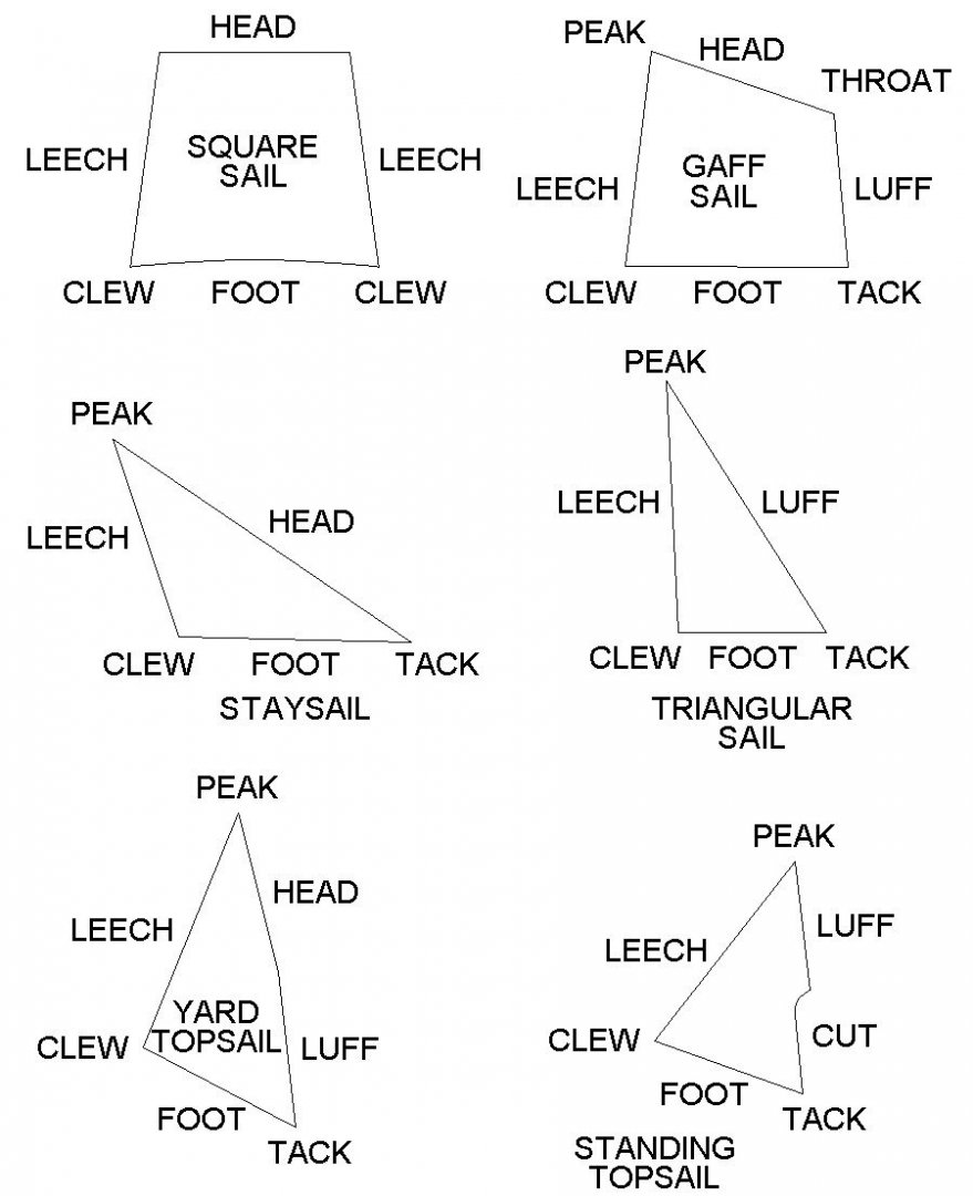


- 104 replies
-
- 20
-
-
-
- schooner rigging
- Topsail schooner
- (and 1 more)