
HOLIDAY DONATION DRIVE - SUPPORT MSW - DO YOUR PART TO KEEP THIS GREAT FORUM GOING! (Only 13 donations so far - C'mon guys!)
×


Dr PR
-
Posts
2,401 -
Joined
-
Last visited
Content Type
Profiles
Forums
Gallery
Events
Everything posted by Dr PR
-
 Yes, it was important to choose the lee side! I thought of the bucket idea and I am sure it was used on some ships. The "honey bucket" was in use in many households until the advent of running water and flush toilets. It would be "normal" to use them on ships.
 -
John, It would help if you could post a photo of a gun and carriage, showing the quoin area. Carriages had a support piece (stool bed) for the quion that rested on the rear axle tree, or sometimes extended over both axle trees. Maybe your carriages have this support but do not have the quoin? If so all you need to do is add a quoin to set the gun elevation.
-
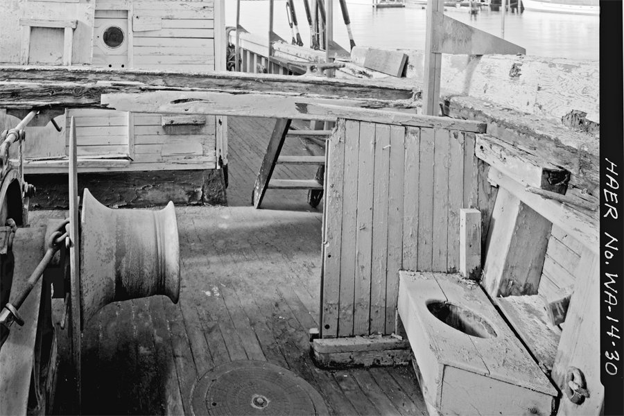
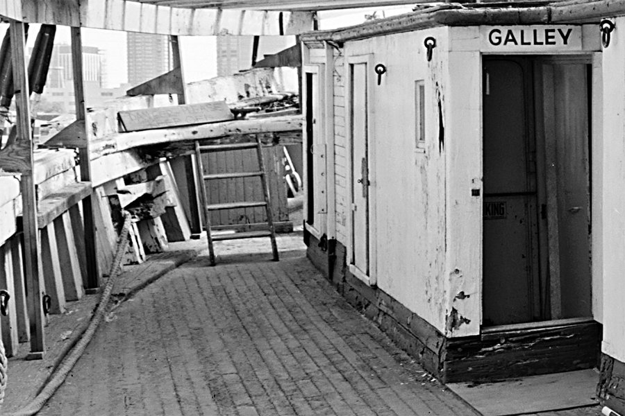
I have been trying to determine where the heads (latrines) were on small to mid sized schooners (60 to 100 foot between perpendiculars) from the late 1700s through the 1800s. I haven't found much information about them. After the bows were closed in with no beakhead I wonder where the seats of ease went? Here are a couple of photos of the Wawona from the Historic American Engineering Records (HAER). It was a three masted lumber schooner built in 1897 in San Francisco, CA, USA. The vessel had a fo'c'sle deck above the main deck at the bow. In this photo looking aft from the bow this overhead deck had rotted away, exposing the winch and the port side seat of ease to the elements. A short "bulkhead" afforded some privacy. Photos do not show the starboard area. The vessel rotted away and was scrapped. In this view looking forward (below) you can see the short bulkhead behind the ladder on the port side leading up to the fo'c'sle deck. Photos of the hull do not show any openings in the hull side in the area where the seat of ease was located. The Wawona was very similar to the C. A. Thayer that is in the nautical museum in San Francisco. But the HAER plans and photos for the Thayer do not show the seats of ease. They show one internal water closet in the aft cabin. So the Wawona photos show one possible solution. Any one have examples of other heads on smaller ships that didn't have the elaborate beakheads like the larger ships? PS: I read through the "Development of External Sanitary Facilities Aboard Ships of the Fifteenth to Nineteenth Centuries" thesis by Joe John Simmons III. It deals mainly with larger warships and has nothing about smaller vessels.
-
McMaster-Carr is a good supplier of materials, fasteners, tools, etc. We have used it in our business for decades, and I get some of my hobby materials there too: https://www.mcmaster.com/ The web site is easy to navigate, and that's good because I think they used to say they have more than a hundred thousand items!
-
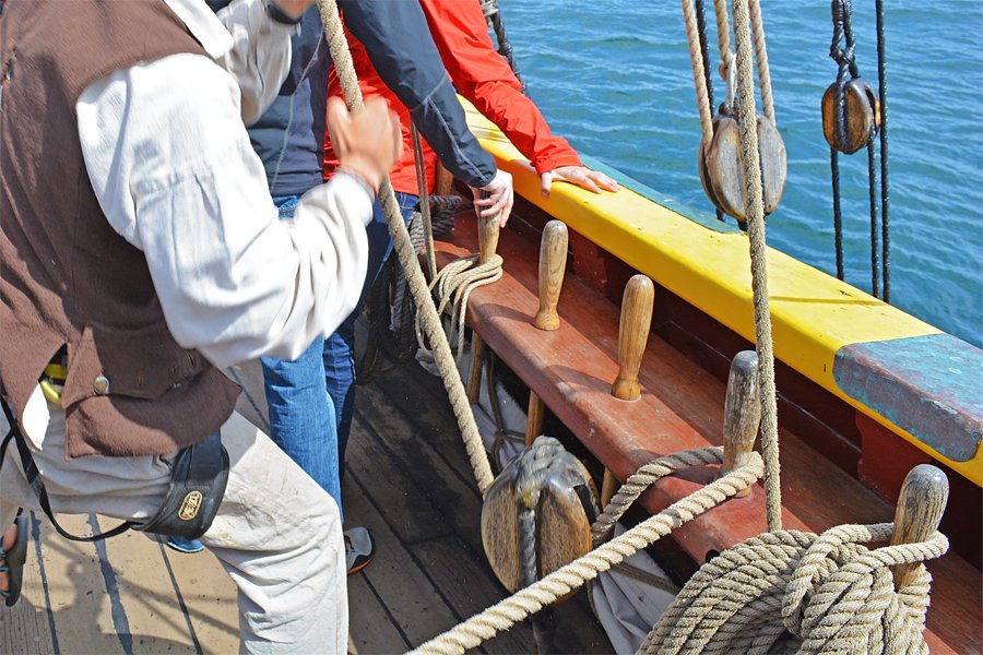
I have also been wondering about size and color of belaying pins for a 1:48 scale model. Here is a photo of pins on the Lady Washington replica ship. This is a working ship so these pins are not museum pieces. Notice how the lesser used pins are a bit shinier than the two with the ropes on them. These may just be spare pins or for occasional use, or maybe new replacement pins. I suspect these were varnished, but a couple hundred years ago the pins probably weren't varnished (too expensive). Oil from sailor's hands might well have darkened them after decades of handling, along with the common fungi that cause wood to turn gray over time. The pin at bottom right sows the "correct" way (according to some people) to attach coils of rope to a pin by pulling one of the last turns through the center of the coil and looping it over the pin - the entire coil does not hang over the pin so much of the pin is visible. Also, the crew was hauling in the line around the second pin from bottom right when the photo was taken. The line runs down through a runner block, then up and around the pin, and was being pulled to the left. The friction of lines on the pins would soon wear off any varnish, so these pins look more weathered.
-
Cleaning Brass Casting Residue
Dr PR replied to Jonathan_219's topic in Metal Work, Soldering and Metal Fittings
You mention a texture to the surfaces. I recall seeing in one of the carving threads on the forum that often the "background" surfaces between carved figures was pitted to create a surface that wasn't smooth and shiny. -
How big will the model parts be? What scale are you working in?
-
It was project 1164, a Slava class. Three were completed back in the 1980s. Moskva. Marshal Ustinov and Varyag. Ukrayina was started but not finished. Ukraine took possession after the breakup of the Soviet Union and it is in Mykolaiv, Ukraine. I think these are beautiful ships, although a bit out dated now. They served in the same flagship role as the USS Oklahoma City CG-5 that I served on. The huge anti-ship Balzat/Sandbox missiles are similar technology to the Talos missiles I worked on.

-
I have been using CAD software for 33 years, and at least 25 years working in 3D CAD, including ship modeling: https://modelshipworld.com/topic/19321-uss-oklahoma-city-clg-5-1971-3d-cad-model/?do=findComment&comment=590228 Learning to use a 3D CAD program is not an easy task for most people. It can take a year or more to become really proficient. Some programs have absolutely horrible user interfaces - what we once called "user hostile." Some of the documentation (if there is any) is abominable, and often incomprehensible. So if you are thinking of getting a CAD program be sure it has a FREE on line user forum where you can get help from other users (like this forum). Don't count on technical support from the company unless you have to pay for it, and some CAD programs charge as much as $2500 per year for technical support, and even to be able to use the user forum! This will be time spent when you are not creating your real model. But once you learn it is an extremely useful tool for figuring out how to build models, and most programs can even create files for 3D printing . **** My experience with 3D CAD newbies (I was a 3D CAD user forum monitor for decades) is that the biggest problem is that they have never "thought" in 3D. This is especially true of experienced 2D CAD users. 3D CAD is not "drawing!" Almost nothing you have learned using a 2D CAD program, Photoshop, Corel Draw and other drawing programs will help you, and will probably be an obstacle you have to get over before you can really work in 3D. In 3D CAD you are modelling in a virtual universe that you create, and you have to think in 3D. You do not create a drawing, you create an object. Some people never achieve this and their 3D CAD attempts are failures.
-
Valeriy, I have been following this model since you started back in 2018. Your workmanship is superb, and the model is beautiful! A person can learn a lot about building a model from scratch by reading thorough this thread. One of the things I find interesting about the Varyag is that even though it was a Russian Navy ship it was built by the Cramp Shipyard in Philadelphia, USA. The cruiser I served on was also built by Cramp, but 40 years later. There were a lot of changes in ship design over those 40 years! I actually came across your build by accident. I was studying the modern Russian Navy Varyag guided missile cruiser and Google lead me here. It was a fortunate bit of serendipity.
-
Justifying the purchase of a mill
Dr PR replied to Captain T's topic in Modeling tools and Workshop Equipment
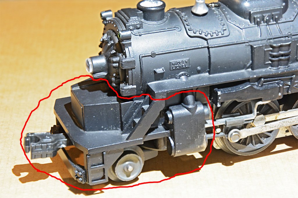
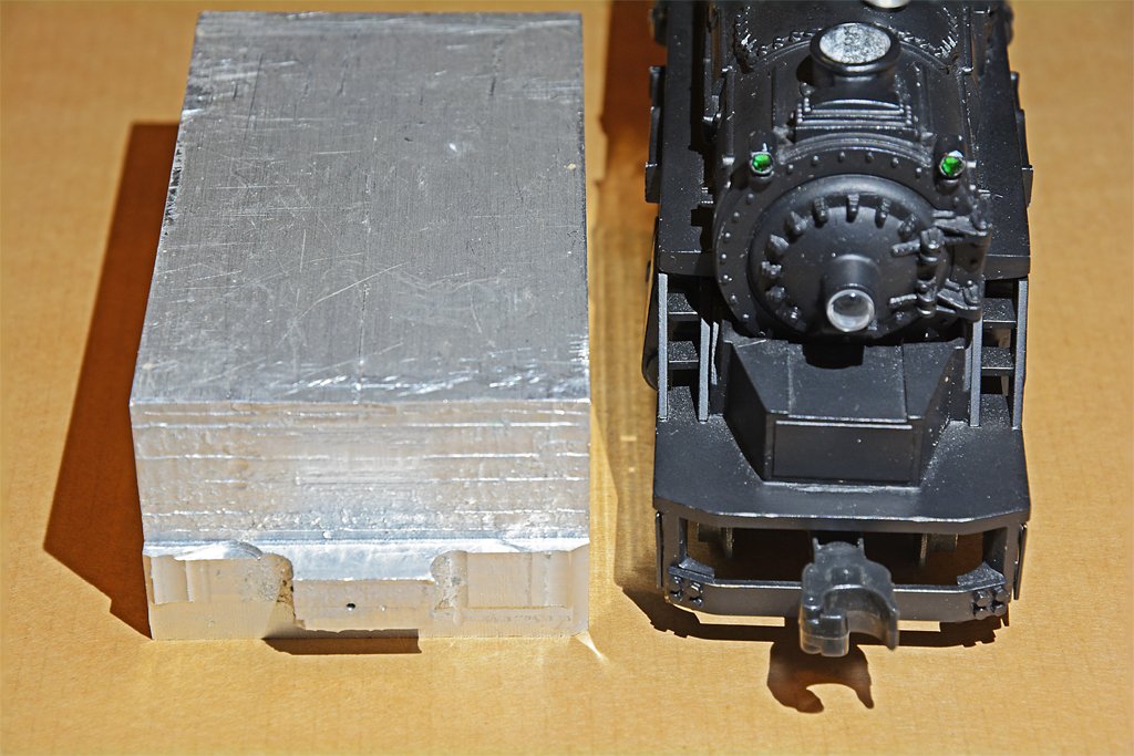
A mill is very handy for two basic types of work. As Tom said above, with a mill you can do precision work when drilling lines of evenly spaced holes (pin rails, etc.) or cutting straight precision grooves. It is useful for making multiple copies of things like the sides of gun carriages, gratings and such. If you get a rotary table you can then make more complicated things like wheels and such. And a dividing head (it has stops for rotation at precise angles) allows precision machining of things like holes for spokes in a wheel hub, etc. Once you get used to working with a mill you can do a lot of interesting things. **** The big difference between a mill and a drill press is that the bearings in a drill press are just designed for single axis up/down drilling. You can position the table below the drill and then drill a hole, but it isn't designed to work with forces perpendicular to the drill axis. You can use a Dremel in a press for milling (I have done this) but if you do this often it will wear out the bearings relatively quickly. A mill is basically a three axis drill press.The bearings in a mill are designed to cut into material moving at right angles to the axis, such as when you use an end mill to carve a groove into a piece of material fastened to the moving table. Especially if the material is steel or brass. And you can do anything with a mill that you can do with a drill press. **** Another thing a mill is useful for is making very specific tools. For example, on an upcoming project I will need about eight feet of a thin brass strip with two rows of alternately spaced rivet heads. For this I will need a special tool. It could be a tool for use in an arbor press that has a custom created punch and die and provision to increment the position of the strip with each successive stamping, or a geared roller arrangement to pull the brass strip through a rotating pair of punch/dies. Either way I will have to make the tool and a mill will be essential for this. A similar tool will create two and three rows of rivets along the edges of hull plates. Another specialized tool will stamp water-tight doors out of 0.003" brass. There are eight different types and sizes of these doors on the ship with different stamped rectangular "bumps" for stiffness and from four to ten dogs, plus rotary handles and levers to operate the dogs. Most of these doors are not available commercially at 1:96. So I am thinking of how to make the dies for use in an arbor press. A similar tool will be used to stamp rivet patterns in external "backing plates" in the hull plating. **** And with the right combination of tools you can even use a mill as a lathe for fairly short pieces - but I can't imagine trying to make threads on a mill! Here are some photos of milled frames I made for a 1:96 Cleveland class light cruiser hull. This is 1/2 inch thick Plexiglas that I salvaged from the scrap bin of a plastics fabrication company next door to where I worked. The fiberglass hull was pretty thin and flexible so I needed stiff frames to pull the hull into shape. This was especially necessary because the hull had a lot of tumblehome (wider at the waterline that at the main deck level, but the mold had to be wider at deck level so the fiberglass shell would come off. I also had to make longitudinal pieces between frames at the deck level to get the correct hull shape. The longitudinals fit into the frames. Everything was epoxied into the fiberglass shell. The frames also served to hold the brass alignment jigs for the propeller shafts. The stern was also a challenge. It is roughly square at the waterline and semicircular at the deck level. The fiberglass hull would not make the correct shape at deck level without the machined Plexiglass shape fitted between the last frame and the stern of the hull. I could have cut all of these shapes with a band saw or even a hand saw, but it would have been a lot more work. On the mill it was an easy task. These things were all cut free-form - I clamped the Plexiglass sheets to the table and used the hand wheels to drive the table so the end mill cut along printed lines on sheets of paper attached to the Plexiglass. Keep in mind that I was using a several ton eight foot high milling machine to cut this thick material in single passes. But a small desk top mill can do the same thing with 1/4 inch Plexiglass, wood, aluminum and other "soft" material. You can cut thin (1/16 inch or less) steel with the smaller mills. You can cut thick material with the smaller machines, but you have to go slower and use multiple passes. Here is another example. This is an old 1950s Lionel O-27 engine that I got as a kid. Later on I got another engine like it, and I wanted to double head them. But the Lionel engines did not have a front coupler. So I replaced the front casting with the machined piece circled in red. It was carved from a block of aluminum, shown on the right. Again, I used the milling machine with an end mill to whittle away material from the aluminum block a bit at a time. I drove the X, Y and Z axes by hand. I used small files to smooth the rounded surfaces of the steam cylinders, and added brass ladders and the brass bar on the front below the coupler - using tiny brass hex head screws from the local hobby shop. The pilot truck, side steps and coupler are Lionel replacement parts for different engines. You really are limited only by your imagination as to what you can do with a milling machine. With a small mill you don't have as much power as with the larger mills so you just have to remove smaller amounts of material with each pass. A larger and more powerful machine will let you work faster than some rig using a Dremel tool.
-
wefalck, I used to have a D5100 but gave it to my youngest grandson when the D5200 came out. I got the D5200 for the 24 megapixel photo element. Extreme contrast images are difficult with any camera. I have made good shots of the moon at night, solar eclipse, etc. The full moon looks bright to our eyes, but it isn't nearly as bright as full sunlight. But it is a LOT brighter than the stars and nebulae! Here is a D5100 Hi-Res JPEG shot taken through a Nikon 70-300 mm FX lens (450 mm effective focal length on the DX series cameras) and cropped to 2048x1366 pixels. 1/320 second at f5.6 with ISO 200 and spot metering. The great thing about digital cameras is instant gratification. With film I had to wait a few days for the pictures/slides to come back. There was no real time verification that the picture came out. With digital you can take a shot, look at it, and adjust as necessary while hopefully the subject is still there. With model/macro photography I try to use the smallest f stop for maximum depth of field and low ISO for noise reduction. Then I just use whatever shutter speed is necessary to make the shot. The model isn't going anywhere.

-
I do a lot of macro photography, wildflowers, insects, etc., and use an excellent macro lens. So I have the camera equipment for model photography. I learned long ago that the best lighting for outdoors work is cloudy bright - a slight thin white cloud layer illuminated by the sun. This gives a nice diffused white light with good illumination from all around and no harsh shadows. Strong shadows are a real problem for most macro work. Of course you can't always have a cloudy bright day, especially if you are trying to photograph something indoors or at night! For indoor work I do not want a direct light. A good white light bounced off a wall or ceiling gives diffuse shadows. For ship model photography I find it best to avoid harsh contrasts from bright lights that leave part of the image underexposed and part overexposed. Low contrast lighting is usually best for illustrations. But when you have a diffused or dim light to avoid harsh shadows you need to use longer shutter speeds, especially if you are using very small apertures for greater depth of field. I mount the camera on a tripod and use up to 30 second exposure with f stops up to 34 or 40 - depending upon the light - to get good depth of field. I use a remote shutter release to avoid moving the camera. Mounting the camera on a tripod allows me to make multiple exposures from the same camera angle. I often do this, adjusting the focus point to different places of interest on the model to get sharp exposures of that part of the model. Then I use photo stacking to get very good depth of field. For example, in this composite image of 12 photos you can see the grain at the end of the bowsprit and the ring bolts on the boat booms on the stern are also in focus. This is a 22 inch (56 cm) depth of field! The diffused soft lighting allows you to see details in the shady bulwarks on the right and in the brighter lighted parts, with no harsh shadows.
-
Rigging Confusions - Lifts, Halyards and More, Oh My!
Dr PR replied to rraisley's topic in Masting, rigging and sails
Rick, I suggest you don't get too anal about the "correct" locations for tying off the rigging. There is a good chance that some things changed during the life of the ship. I modeled a mid 20th century light cruiser that was in service for several decades and there were dozens of changes over the years. Some were simple, like the bosun wanting another cleat or bitt to tie to, or new antennas to improve reception. Others were large like adding new compartments on deck of adding new equipment. But in every case the changes were made to improve the performance of the ship. I doubt that this idea was new to the 20th century! I would not be surprised to learn that 15th through 19th century ships had occasional changes to the rigging to make it "better" in the eyes of the current Captains. There are some recorded accounts where rigging and sails were changed because a "better" way was observed on another ship. Unless you have an accurate period rigging plan for a ship for the year you are modelling you will never know exactly how it was rigged. There are a few simple rules of thumb for rigging that comes from some period books on rigging ships. 1. Standing rigging like stays form triangles with the mast and deck in order to support the masts. Forward stays fasten on or near the ship's center line on deck or to the bowsprit. After stays attach to the bulwarks or channels outboard the bulwarks. 2. Running rigging from the lower spars and sails leads to the forward most points on pin rails, fife rails and belaying points on deck, and the rigging from the highest points leads to the aft most belaying points. Rigging from near the center of yards or the mast leads down to points near the base of the mast (fife rails, ring bolts on deck, etc.) and rigging from the yard arms and outboard parts of sails leads down to points along bulwarks, pin rails or ring bolts on the deck near the bulwarks. Mast tackles usually lead outboard to channels or pin rails. 3. Lines should not cross or rub together. Each must lead free and clear down to the belaying point. Since this is how ships have been rigged for centuries, if you follow these guides you will probability end up rigging the model almost exactly like the real thing. -
Resistance Soldering Unit
Dr PR replied to Roger Pellett's topic in Metal Work, Soldering and Metal Fittings
Looks like the current 100 Watt model. The user manual and other information can be found here: https://americanbeautytools.com/Resistance-Probe-Systems/110/features I have a little experience with resistance soldering with an American Beauty 250 Watt unit. Part of the probe is a carbon electrode which is VERY brittle and breaks easily (really annoying). The carbon electrode does not react with the metal being soldered. A metal probe might arc and scar the piece being worked on, or might even weld itself to the piece, depending on the materials and current. You can use an alligator clip to connect the return circuit to one of the pieces being soldered (preferably the larger piece. However, this will create several tiny point contacts with the work piece, and you might get some arcing and pitting. Many people recommend using a large sheet of conductive metal (copper,steel, etc.) as a base and clamping the larger work piece to it to get a good electrical connection. Then the probe is positioned against the other work piece before power is turned on. The carbon probe has a relatively high resistance and therefore heats up as current flows through it. Some of this heat transfers to the work piece, but it is heat generated in the solder that causes it to melt. -
Marcus, zu Mondfeld's "Standing rigging sizes" table on page 272 and "Running rigging sizes" table on page 308 have an error. This had me scratching my head for a while. They say "The figures given refer to the thickness of the main stay, 0.166% of the diameter of the mainmast at the deck (100%)." The actual number is mast diameter x 0.166, or 16.6% of the mast diameter. The resulting number is the circumference of the rope, not the diameter. Divide the circumference by Pi (3.14159) to get the diameter of the rope. **** Before I figured this out I was getting really strange rope sizes. For example, 0.166% = 0.0016. If a model's mast was 0.375 inch diameter I thought the rope diameter was 0.0016 x 0.375 = 0.0006 inch! That is about 1/5 the thickness of a sheet of 24# printer paper! That is way too small and obviously incorrect. So I tried 0.375 inch times 16.6% = 0.375 x 0.166 = 0.062 inch, or about 1/16 inch. But 1/16 inch diameter seemed much too large. Then I realized it meant a 1/16 inch circumference, or 0.0625/3.14159 = 0.019894 or 0.02 inch diameter rope for the main stay. All other rigging circumferences are based upon the main stay circumference. **** In my schooner rigging spreadsheet I used Lees' formulas for English square rigged ships. But mast diameters are smaller on schooners that on full rigged ships. So reducing the mast diameter for schooners also reduced the size of the ropes used for the rigging. However, the rigging size section of the spreadsheet is not linked to the masting part. There is a separate cell (BH9) for the rigging calculations where you enter the model's mast diameter. So for any ship type just enter the mast diameter and the spreadsheet will use Lees' rules and calculate all the rigging sizes. However, I only include the rigging used on a schooner (and not all of that it turns out - I am learning). But the spreadsheet is not locked so you can modify it however you please. CAUTION: The spreadsheet uses Lees' English unit formulas and some calculations contain English feet to inch conversions, so entering metric values for the mast diameter will result in some meaningless Metlish measurements! If you want metric values enter the mast diameter in inches and then add a column to the calculations to convert the English units to metric units. Or just rewrite the spreadsheet. Mast spar and rigging calculations.xlsx
- 19 replies
-
- 6
-

-
- running rigging
- standing rigging
- (and 1 more)
-
Bill, I am kitbashing a topsail schooner kit into a hypothetical revenue cutter of about 100 tons. https://modelshipworld.com/topic/19611-albatros-by-dr-pr-mantua-scale-148-revenue-cutter-kitbash-about-1815/?do=findComment&comment=598658 Take what you see on my link with a grain of salt. It is constructed "like" what a revenue cutter of that size might have looked like, but it is not a model of a real ship. For me it is a learning exercise. But there is a lot of information about Baltimore clippers and revenue cutters. There aren't a lot of plans available for American schooner revenue cutters, and they aren't highly detailed. Howard Chapelle's "The Baltimore Clipper" is the most detailed book I have seen, but there aren't detailed plans for any revenue cutter. Chapelle's "The History of American Sailing Ships" has plans for two revenue cutters, Morris and Joe Lane. He also discusses the 31, 51 and 80 ton designs of William Doughty. Kits of these designs are available. Chapelle's "The History of the American Sailing Navy" has plans for the revenue cutter James Madison, Roger B. Taney and Washington. If you do get this book look for the 1949 version by W. W. Norton and Co. It has two page fold out plans for many ships (no revenue cutters). The newer Salamander Book version has the drawings split on two adjacent pages with details lost in the fold. When you get to the rigging stage you might find information at this link useful: https://modelshipworld.com/topic/25679-topsail-schooner-sail-plans-and-rigging/?do=findComment&comment=750865 It explains a lot of the terminology and describes the various parts of the masting and rigging of topsail schooners.
-
I would think the vangs would be led forward near the base of the mast. That way they wouldn't interfere with the swing of the booms. On some schooners the vangs are attached to hooks so they can be moved easily when necessary. The lee (downwind) vangs do not need to be tightened but they should be ready in case the wind shifts or for sudden turns.
- 162 replies
-
- 2
-

-
-
- america
- BlueJacket Shipcrafters
- (and 1 more)
-
Topsail schooner sail plans and rigging
Dr PR replied to Dr PR's topic in Masting, rigging and sails
Thanks. I agree with what you have said. Marquardt uses the term "roach" for the concave foot (bottom edge) of the sail that allows it to clear the stays, referring in one instance to an extreme roach up to 2/3 the height of the sail. I think I have seen "gore" used to refer to the extended belly of the sail, but I will have to see if I can find that reference. In any case, when I see "roach" or "gore" I can at least think that the author is probably talking about the bottom of a sail. I also chuckle at some of the modern dogmatic arguments about the differences between this and that sail rig. One author pointed out that the difference between a topsail schooner and a brigantine is that when a vessel has the fore gaff sail (fore sail) raised it is a schooner, but when the gaff sail is lowered and a fore course (square sail) is raised it is a brigantine. But I have photos of vessels with both the fore gaff sail and a fore course raised at the same time. So is it a "schoonatine" or a "brigooner?"- 104 replies
-
- 3
-

-
- schooner rigging
- Topsail schooner
- (and 1 more)
-
Topsail schooner sail plans and rigging
Dr PR replied to Dr PR's topic in Masting, rigging and sails
wefalck, Good questions! One thing I noticed right away is the very long list of references (more than 100) that he quotes. Although some things he writes are speculative - and he says so - most is based upon period writings. Likewise, he has many dated illustrations to reinforce his claims, although he sometimes sees details in sketches and paintings that I cannot see! You are probably right about his use of terms from numerous languages. He states that the word "schooner" did originate in America, but might have been from a Dutch colonist who use the Dutch word "schoone," which means "beautiful" and that New Englanders often added a "r" sound to the words ending in a silent "e" to produce "schooner." And he notes that in Dutch "ch" is pronounced like the English "sh" but in America "ch" is pronounced like "k"in English. So we have the word "schooner" (pronounced "skuner" in America). Maybe. A very interesting point he makes is that before the word "schooner" appeared in America in the early 1700s the schooner rig was not called a "schooner." The Royal Navy didn't start using the term until the mid 1700s. However, the first true schooner rig may have been the HMS Royal Transport of 1694 (he has numerous drawings and photos of an original model of the vessel). Before "schooner" came into use schooners were called "sloops" and some other terms. Some authors credit the invention of the schooner to America (and who of us who are true blue Americans would doubt that?) simply because there are no reports of "schooners" in the fleets of the world before they appeared in American reports. But he reprints many earlier drawings and illustrations of schooner rigs in Europe (especially The Netherlands) long before the term came into use in America. Marquardt's history is very well researched! But in his history of the fore-and-aft rig he says nothing about the history of the lateen (latin) rigged vessels of the Mediterranean and Arab world! One of the undefined terms he uses many times is "cutter mast." I can find no other reference to this term. However, he does have one drawing of mast types with a "cutter mast," but no explanation of what the difference ifs from any other mast. There doesn't seem to be anything unique about it. Another ambiguous term is "roach" which I think is the same as the undefined term "gore" that other authors use to describe the curvature of the foot of a sail. He uses the term "schooner sail" to refer to only the fore gaff sail with a boom. Without a boom is is not a "schooner sail." But the main gaff sail with a boom is not a "schooner sail," even though it is found on almost all schooners! Again I can find no other reference for this peculiar term. But even with a few faults it is an excellent reference for schooner masting and rigging, the equivalent of James Lees' The Masting and Rigging of English Ships of War (which also has a lot of undefined terms and nothing about schooners). Marquardt does reference numerous authors who have published details about schooners, and has comparisons of the different calculations. There are 23 tables of schooner masting and rigging dimensions in the Appendix, from Frederick H. auf Chapman 1768, Paris 1769, Steel 1794 and 1818, Falconer 1815, Fincham 1854, Steinhaus 1858, and Brady (US Navy Board of Navy Commissioners) 1876. Another example of Marquardt's work that I have is Captain Cook's Endeavor in the Naval Institute Press "Anatomy of the Ship" series, 1995. Just about every part of the ship is illustrated. He has similar (but not as extensive) drawings for half a dozen schooners in his Global Schooner book. And the various parts of the rigging are illustrated with as much detail as in the Endeavor book. And one other bonus for those "down under," Marquardt describes a few Australian and New Zealand schooners. Where else will you find that?- 104 replies
-
- 2
-
-
- schooner rigging
- Topsail schooner
- (and 1 more)
-
Topsail schooner sail plans and rigging
Dr PR replied to Dr PR's topic in Masting, rigging and sails
Gregory, I have not seen McGregor's The Schooner. The reviews on line are not especially flattering. One says it has few detailed plans, another says there are some. Does he give tables of dimensions for the parts of masting and rigging? If so, is he just repeating what someone else has written, or is it original research? I did note it is another Naval Institute Press book. McGregor is a well-known author of books about ships. I have McGregor's British and American Clippers. It has a lot of history, and quite a few drawings of ships, but very little construction detail. The index lists ship names and people involved in the shipping industry, but nothing about the individual parts of ships. So even if there was detailed information about the construction of a part of a ship I would have to search through the entire book to find it. And there is no glossary where the author defines the terms he used. Although I am interested in nautical history, for ship modeling I really don't need a lot of detailed history. I am looking for illustrations of how the parts of ships were constructed and not a long winded history of how the particular design came about, who the designers were and their personal histories. Compare this to Harold Underhill's Masting and Rigging the Clipper Ship & Ocean Carrier, Brown Son and Ferguson, Glasgow, 1972. It is one of the best (perhaps the best) nautical books I have seen. The 12 page Index contains about 1500 entries (at least 3000 page links) and almost all are for specific details of masting and rigging. Want to know what a "lower studding sail tripping line" is? Page193. Almost every detail is illustrated, and he gives the formulas for calculating various parts and numerous tables for determining proportions of masts and spars. There isn't a separate glossary, but he does define every term he uses in the text linked to in the index. He also gives some brief histories of how and when each part came into use, plus a bit of history of the development of ships rigging. It is a must have book for modelling British clipper ships of the late 1800s and early 1900s!- 104 replies
-
- 4
-
-
- schooner rigging
- Topsail schooner
- (and 1 more)
-
Well spoken Valeriy! I have written a few books and it is a lot of work and a real time consumer! It just doesn't leave enough time for the more important things in life - like building ship models!
-
It has been a while since my last post. I am working on details on the hull before taking on the masting and rigging. I have decided upon the rigging and created a spreadsheet to determine sizes and lengths of different size ropes and the sizes and numbers of blocks and such. I placed the order from Syren Ship Models and was able to get what I need before Chuck runs out of stock (I hope - the order has shipped but I don't have it in hand yet). There is a new twist to my plans. Eric William Marshall recommended another book, "The Global Schooner" by Karl Heinz Marquardt, Naval Institute Press, Annapolis, Maryland, USA, published by Conway Maritime Press, London, 2003. It is the best book I have seen on schooner masting and rigging! I am about 2/3 through the book. After I add Marquardt's formulae to my spreadsheet I may make some changes to my plans for the dimensions for masts and spars.
-
Topsail schooner sail plans and rigging
Dr PR replied to Dr PR's topic in Masting, rigging and sails
I have a new reference to recommend thanks to Eric William Marshall who told me about it. "The Global Schooner" by Karl Heinz Marquardt, Naval Institute Press, Annapolis, Maryland, USA, published by Conway Maritime Press, London, 2003. This book is devoted to the history and construction of schooners. It has an exhaustive history of the schooner rig - the best I have seen. Did you know that the fore-and-aft rig was inspired by a Peruvian raft from the early 1600s? The book has very detailed chapters on masts and rigging with detailed drawings. Numerous tables in the appendices give rules and dimensions for mast, spars and rigging. It is the most complete text on schooner rigging that I have found. It is a large book (11.6 x 10 inches, 294 x 254 mm) with 239 pages containing many detailed drawings, full page ship plans and illustrations. The only drawbacks are poor proofreading (some text is misplaced and a few drawings are mislabeled) and the author uses numerous undefined terms that I cannot find in other books on ships' rigging. In a few cases the text is so ambiguous I can's tell what he is talking about. These are minor problems, and common to most books about sailing ships. It has a good index but no glossary. There is no list of drawings and illustrations, and that would help finding the drawings the author often refers to. When I have time I will add Marquard's rules to my masting and rigging spreadsheet.- 104 replies
-
- 4
-
-
- schooner rigging
- Topsail schooner
- (and 1 more)
-
I recall seeing a very nice large scale (1:96 or 1:48?) model of the USS Oregon in the maritime museum in Astoria, Oregon, about 45 years ago. I visited again a few years ago and the model wasn't there any more. I have no idea what happened to it.

