


Dr PR
-
Posts
2,401 -
Joined
-
Last visited
Content Type
Profiles
Forums
Gallery
Events
Everything posted by Dr PR
-
I believe the tackle used to position the studding sail booms was temporary, and not left rigged permanently. It was taken aloft to rig the sails. On smaller ships the booms may have been manhandled to push them out or haul them back in. When in position in/out the inboard end of the boom was lashed around the yard to hold it in place.
-

Ships vs Boats
Dr PR replied to Mike from Aus's topic in Using the MSW forum - **NO MODELING CONTENT IN THIS SUB-FORUM**
I have to add my two cents here! My first "ship" was a 112 foot long inshore mine sweeper (MSI). Three officers and 19 enlisted. I was Engineering Officer, Supply Officer, George and 25 other official duties. I was told, when first going aboard, that ships in the US Navy were 150 feet or longer, and anything smaller was a boat. However, we had a letter from the Secretary of the Navy authorizing us to call the vessel USS Cape, United States Ship. So the Cape and her sister the Cove (MSI 1) were the smallest ships in the Navy. The Cove was probably a bit shorter than the Cape. The ships had four GMC 6-71 diesel engines ganged together to drive one 4 foot diameter bronze propeller and a 6" diameter prop shaft. The prop and shaft weighed more than the engines. If we tried to shift into reverse while the shaft was turning the momentum of the prop and shaft plus the force of the prop "windmilling" would just crank the engines over backwards, and they were happy to run that way! To reverse the prop we had to pull on a brake lever that tightened a brake shoe against the shaft and hold on until the shaft stopped turning. Then we could shift the transmission into reverse, rev up the engines, let out the clutch and start the shaft/propeller turning again. Ditto when going from reverse to forward again. All this messing around took several minutes and made close maneuvering tricky. Why am I telling this? One time when coming in to the pier the Cove timed the approach wrong and while trying to reverse engines to slow down it rammed the stern of a destroyer in the berth ahead. It cut a several inch deep "V" shaped notch in the destroyer's stern. The destroyer presented the Cove with a new name plate for the "USS Can Opener." So the Cove was probably the shorter of the two. And there were only two. They were worthless. PS: One of these days I may build a model of the Cape. A wooden model of a wooden ship. -
Triangular skysails on USS Constitution?
Dr PR replied to Smile-n-Nod's topic in Masting, rigging and sails
Bob, Thanks for that information. I have seen pictures of schooners with this type of topsail, but I had no idea what they are called. -
Some vessels had gaff vangs and others didn't. But without the vangs the only control of the gaff was through the gaff sail, and that wouldn't prevent the gaff from swinging side to side as the ship rolled. Only the windward vang had to be taut to control the gaff swing. The leeward vang could be loosened to allow the boom to swing outboard. The vangs were typically hooked to ring bolts in the deck, and slack vangs could be unhooked and lead forward to get them out of the way of the boom.
-
Has Anyone Used Surgical Binocular Loupes
Dr PR replied to rraisley's topic in Modeling tools and Workshop Equipment
I have a couple of the cheap Optivisor type with plastic lenses. They were OK at first but the plastic scratches easily, and after a while the image deteriorates. Optical glass is much better. Stronger (higher diopter) glasses are a convenient way to go, but they cause eye strain after a while. -
Mantua "blue painted" photo-etched brass
Dr PR replied to Alexisgm97's topic in Metal Work, Soldering and Metal Fittings
If you use very fine grit sandpaper (400 or better) and lay the sheet flat, grit side up, you should be able to rub the photo etch sheet over it to remove the resist without rounding the edges of the pieces. Rubbing with #000 or #0000 steel wool will probably round the edges, and it can get tangled in the finer etched parts and bend them. I remembered that the sodium hydroxide solution was used to remove a pressed on resist film. It doesn't take much on the surface of brass to block the etching solution. I used to make "printed" circuit boards by drawing the traces on the material with water proof Sharpie pens (laundry marker type). After etching acetone removed the ink. -
I have been cutting brass (and even a bit of copper years ago) using an ordinary variable speed hand drill. I just hold the drill in my lap and use the lock on button to keep it running without having to pull the trigger. I adjust the speed screw to get a fairly slow speed. I use a set of very small files to cut grooves, and a razor saw to part off the piece. I also use the drill and saw to cut pieces of tubing. Of course, with this hand held method no two pieces are the same, so I just make a lot more than needed and pick a collection of pieces that are of adequate dimensions. Also, after cutting tubing sections I can file/sand down the ends to get matching lengths. It is certainly not precision work, but it produces "good enough" parts. Maybe some day I will cut down the cabinets in the end of my garage and make a work bench. Then I can get a milling machine and lathe (I used to use the tools at work). But then I will have to insulate the garage so I can work in winter (and protect the machines from temperature and humidity extremes). And I will have to add electrical circuits for the new machinery. Then I will have to add heating ducts to the furnace to heat the work area, and then ... When will I find time for modelling?
-
Mantua "blue painted" photo-etched brass
Dr PR replied to Alexisgm97's topic in Metal Work, Soldering and Metal Fittings
One of the chemicals used for an etch resist stripper is sodium hydroxide (NaOH), a strong base/alkali. Caution: NaOH will cause skin burns and eye damage. Since NaOH is a base, and is used to remove resist, acids probably won't work. Besides, acids will attack the brass. Etchants are usually water based, so most water soluble solvents probably won't work (alcohol). First I would try acetone or enamel or lacquer thinner and an old tooth brush. These solvents won't harm the brass. If they don't work try sodium hydroxide. -
Has Anyone Used Surgical Binocular Loupes
Dr PR replied to rraisley's topic in Modeling tools and Workshop Equipment
I have a friend who had lens replacement for cataracts - and paid extra for proportional lenses. They work well for close-up but she needs glasses for distance! I haven't use the type of loupe you link to. It looks like it would be quite a bit of weight resting on the bridge of your nose. My close up vision has been deteriorating for a number of years, and I have some astigmatism. I do use a different form of magnifier, a multiple lens visor. It works well and isn't uncomfortable. It is similar to this visor: https://www.amazon.com/Headband-Magnifier-Head-Mounted-Binocular-Magnification-1-5X/dp/B07M7H3P95/ref=sr_1_3?dchild=1&gclid=CjwKCAjwr_uCBhAFEiwAX8YJgaKGKYBCNNWnWEE_WXJ37_cq0yNJZmiRivPrrIzlpNVpI4N6rl3ILxoCHU0QAvD_BwE&hvadid=241934970686&hvdev=c&hvlocphy=9032979&hvnetw=g&hvqmt=e&hvrand=13202486322252462774&hvtargid=kwd-339304622&hydadcr=24660_10400764&keywords=magnifier+visor&qid=1616903724&sr=8-3 -
Thanks. I suspected that, and was considering it. I have used black craft paper of appropriate thickness for grout on other models.
-
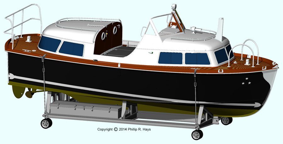
Mike, I love these wooden runabouts too. I grew up in a tourist trap surrounded by three lakes and there were swarms of these back in the 50s and 60s. Nice models! I checked your other build and I have a question. What did you use for the white grout on the deck? I have considered building the Admiral's barge from a ship I was on and it had the mahogany deck with white grout.

- 10 replies
-
- 1
-

-
- Chris-Craft
- Chris-Craft Runabout
- (and 2 more)
-
Electric sanding belt file
Dr PR replied to Don Case's topic in Modeling tools and Workshop Equipment
There is nothing new about tool rip offs. My dad was a mechanic and carpenter, and he had a lot of tools made in the US in the '40s, '50s and '60s. In the early '70s after he wore out his 25 year old Skill saw he bought a new Black and Decker saw from a local store he had done business with for years. A few months later I saw what appeared to be the same saw in a Krap Mart ad for about half of what dad paid for his. He was curious and we went out to have a look at it. It looked just like his, but when he looked it over he noticed that it had cheap brass/bronze bushings on the armature shaft instead of the roller bearings on his saw. A little more inspection revealed a few other cheap substitutions. It was made overseas. The lying marketing scum called it a heavy duty carpenter's saw! -
How to connect yards to masts??
Dr PR replied to ObviousNewbie's topic in Masting, rigging and sails
I posted a bit about trusses, truss pendants and truss parrals (all often referred to as just Trusses) on this post: -
How to connect yards to masts??
Dr PR replied to ObviousNewbie's topic in Masting, rigging and sails
I recently posted drawings of three types of trusses used to hold yards to masts. Unfortunately I cannot locate that thread right now. If I do I will post a link here. -
Allen, My drawing of the stunsails was based upon Darcy Lever (The Young Sea Officer's Sheet Anchor, page 65) drawings and text for topmast studding sails (the drawing is for a topsail schooner). The line nomenclature is directly from Lever. The "loose footed stunsail" drawing you posted is based on drawing number 352, and if you read Lever's text you will see that he does not use the term "loose footed." He refers to it as a stunsail that is "set flying" without a boom. In fact, Lever doesn't define "loose footed" in his "Dictionary of Sea Terms." Biddlecomb (The Art of Rigging) also does not say anything about "loose footed" sails, but he does mention stunsails without booms as "flying." I suspect the term "loose footed" may not have been in use in the 1700s and early 1800s and may be a more modern term However, the drawings you posted are not from Lever, but are from Lees (The Masting and Rigging of English Ships of War, page 116) and are relatively new (1979). He uses the term "loose footed" with respect to Lever's "flying" stunsail drawing. Harold Underhill (Masting and Rigging the Clipper Ship and Ocean Carrier, page 125) refers to a "loose footed spanker" that had no boom. John Leather (The Gaff Rig Handbook) defines "loose footed" as the bottom of the sail not laced or "bent" to a boom with rope bands or robands. In contrast it is common for a gaff sail to be laced (to the upper gaff and to the lower boom. But there is a fore and aft rig in which the bottom of the gaff sail is unattached to a boom, and it is called "loose footed" and "boomless gaff sail." Of course the the tack and sheet are attached to something, otherwise the canvas would just flap in the wind. **** Note the difference between a stunsail boom and a stunsail yard. Stunsail yards are the spar the the head (top) of the sail is bent (laced) to, and it is not attached directly to anything but is hoisted by the halliard. Or, as in figure 352 the foot (bottom) of the "flying" stunsail is attached at the clews to an unattached yard that has a guy to haul it down. The yards are essentially free to swing on the halliards and guys. The booms are definitely attached to the course, topsail and topgallant yards, or in the case of the lower stunsail the (swinging) boom is attached to the hull, typically in the channels. The booms are held to the yards with irons and there are several ways to rig them with the booms stowed or extended. In some cases the booms were permanently attached to the yards, and on some ships they were stowed below (to reduce tophamper weight) and hauled aloft when the stunsails were set. In all cases except the "flying yard" the foot of the stunsails were attached to the booms with tacks (outboard clew) and sheets (inboard clew).
-
Pat, Yes, the relative lengths are my calculations. I was surprised to see that they came out very consistent over a large range of ship sizes. I understand your problem finding information in Lees. I sometimes have trouble with it too. On my topsail schooner project I could find very few "rules" for masting and rigging, and they all were for English ships. One of the interesting things about the American topsail schooners of the early 1800s is that they invariably put aloft longer masts and spars and larger sails than the British. This made them faster but trickier to handle. I determined my own rules by examining drawings and working from published data for a bunch of American schooners. So lacking any other option I looked through the tables in the back of Lees. As it happens I was just coming to the same question about stunsail booms and yards as you did.
-
Rivets?
Dr PR replied to Nirvana's topic in Painting, finishing and weathering products and techniques
Roger, You are correct about flush head rivets on more modern ships, but early iron hull ships up to the 1920s did have domed rivets on the hull exterior, at least above the water line. They are clearly visible in some photos. The blueprints for the Cleveland class cruisers that I am familiar with say that countersunk head (conical head) rivets were to be used. Then the heads were to be ground flush with the plating below the water line to reduce drag. Unless you were very close to the hull you couldn't see any trace of the rivets, especially after it was painted. The blueprints also say that where plates of different thickness are butted together below the water line, the edge of the thicker plate was to be ground down at a 45 degree angle to the level of the thinner plate, again to reduce drag. The conical head rivets were called "countersunk" or "countersunk round" where the head had a slight convex curvature. Large pan head rivets have a head that is shaped like a truncated cone, larger at the base and narrow on top (trapezoidal cross section) . Small pan head rivets have a more cylindrical head. -
Anyone ever hear of Captain Charles Noble? The amount of brightwork (metal) on a ship depended upon the crew and the officers. I was Engineering Officer on a small minesweeper - the "flagship" of the squadron. The crew kept all the brass piping, engine valve covers, gauges and such in the engine room polished. It was their doing, not mine, because they took pride in their engine room. Of course, since we were bolted to the pier most of the time, polishing brass was about all the watch crew had to do. When I went aboard the cruiser (another flagship) most brass was painted. The Captain was a no nonsense man who was commanding a ship of war. After 12 years on cruisers he could drive the 15,000 ton ship like a sports car! The awnings were gray and the metal was painted gray. We got a new XO who wanted to polish all the brass and paint the piping in a rainbow of colors (not the standard navy engineering colors). I was on the bridge when the XO was explaining his plans to the Captain. "Rodney," the Captain said, "you want to turn my ship into a circus boat!" Then that Captain left and we got a new Captain who had spent most of his career commanding a LMD (large mahogany desk). I'm not sure he knew the difference between the pointy end and the blunt end. I don't think he ever took the conn. The XO talked him into making changes, and pretty soon our circus boat was decked out with white awnings, McNamara's lace, and polished brass. The XO went around with a pocket knife scraping paint off of everything looking for brass. Woe be it to the Division Officer who had painted brass! So, to be "historically correct" you would have to model a particular year and know how the officers and crew wanted the brass to look. PS: Ever been in port after a bunch of ships "blew stacks to clear out the soot? White awnings don't stay white very long. There is a reason they were usually gray. PPS: Captain Charles Noble insisted that the brass galley stack on his 1850s English merchantman stay brightly polished. To this day the galley stack on ships is called the Charley Noble.
-
Deck planking methods
Dr PR replied to allanyed's topic in Building, Framing, Planking and plating a ships hull and deck
Allan, On my current build I started at the center line as you described, laying the first two planks on either side, and worked outward from there. After a few planks I cut the openings for the masts, hatches and deck house. The deck house and hatches have coamings cut to match the camber. I nibbed the planks into the margin boards. I had never done this before, and to my astonishment they came out symmetrical! It was a lot easier than I had imagined. https://modelshipworld.com/topic/19611-albatros-by-dr-pr-mantua-scale-148-revenue-cutter-kitbash-about-1815/?do=findComment&comment=603771 However, some ships did have a single plank laid along the center line, and sometimes these planks were wider and thicker than the outboard deck planks. Sometimes there were several wide planks at the center with narrower planks outboard. And some smaller ships (schooners, etc.) and boats had a wide center plank and the outboard planks were bent to follow the curvature of the hull and nibbed into the center plank. So you need to know how the planking was laid out for the particular ship you are building. -
What were your first tools as a child?
Dr PR replied to FlyingFish's topic in Modeling tools and Workshop Equipment
My dad was a mechanic and carpenter. My first tools were whatever I could find in his tool boxes. But woe be to me if I didn't return them! When I was seven or eight I got a switchblade knife from my older brother (who wasn't supposed to have it) that I used for wood carving. One day I sharpened it razor sharp, and no sooner than I had finished it snapped shut on the knuckle of my index finger. Lots of blood and I could see the ends of the vein it had severed. Mom was a nurse and was in the bathroom bathing. I knocked on the door and said I had cut myself - I didn't mentioned the severed vein and pool of blood. She asked if it was serious or if I could wait a minute. Well I wasn't dying so I put my finger over the cut and waited. When she came out I had already put a band aid on it and told her it was OK. She probably would have wanted to put in a couple of stitches. I still have the finger but the scar has long since disappeared. I didn't get to keep the knife after Mom found out about it. -
I use a narrow kerf hobby saw or jeweler's saw to trim the ends fairly close to the frame. Then I use coarse sandpaper (160 grit) to smooth things and finish with fine grit (320-400). I also have some files that work with most woods, but I think the sandpaper gives me better control. Just place a sheet on the workbench grit up and drag the grating across it.
-
Lees gives examples of sunsail boom lengths on page 194 for ships of 1716 and on page 204 for 1838. Stunsail boom length 1716 100 gun 1716 70 gun 1838 1st class 1838 3rd class 1838 frigate main yard length x 0.56 0.56 0.57 0.58 0.57 topsail yard length x 0.64 0.63 0.71 0.70 0.71 topgallant yard length x - - 0.80 0.78 0.79 The numbers are pretty consistent regardless of ship size. Maybe a bit smaller in the early 1700s than in the 1800s. Stunsail yard lengths Lees does say the sunsail yards were about 1/3 the length of the yard up to 1745 and then about half the length. However tables in the back of Lees (page 200) give actual dimensions. For a 110 gun ship of 1815 the stunsail yard lengths on the main mast were 0.37 (main yard), 0.4 (topsail yard) and 0.44 (topgallant yard) times the length of the yards. There are some variations in the numbers for different sized ships, but they are still in the range of 0.35 to 0.45 of the yard length. The tables on pages 194 and 204 also give stunsail yard dimensions for several ship sizes. Lees gives data for English ships. Some American ships of the 1812 period carried excessively large tophampers, so the spar lengths may have been longer. I wouldn't get too hung up on precise boom/yard lengths. These things varied with different ship builders and different periods. Close is good enough unless you have an accurate spar dimension table for the ship you are building.
-
Mike, Lees has detailed information in the back about the circumference/diameters of rigging. It is all based upon the mast diameter. However, the rigging dimensions are for the circumference of the ropes. Divide by Pi (3.14159) to get the diameter. I am attaching a spreadsheet I made for my current build, a topsail schooner. This spreadsheet contains most of the formulas for mast/spar/rigging dimensions from Lees and Mondfeld. However, some of the upper masts and yards that are not found on schooners were omitted. You have to enter the hull dimensions (explained in the drawing) in the appropriate green cells. CAUTION: Although the calculations for each part are valid for any ship, the second set of calculations are for the lower mast dimensions of schooners. Schooner masts were typically only 3/4 as large as square-rigget masts. So you need to pay attention to the part for determining mast dimensions (based upon the ship's beam). Once you know the diameter of your masts you can plug it into the appropriate green cell and all the calculations will be done automatically. I deliberately did not carry the calculations for mast dimensions through the whole spreadsheet. You have to enter the numbers in several places (green cells). In this way the first set of calculations are for full rigged ships, the second part for schooners, and the final rigging part is for all ships. The spreadsheet also calculates the proper block dimensions to be used with each rope size. Mast spar and rigging calculations.xlsx
-
Sloping deck
Dr PR replied to Don Case's topic in Building, Framing, Planking and plating a ships hull and deck
Camber is also used today for the curvature of a road surface from side to side, higher in the middle. So i suppose it could apply to any surface that is curved to be higher in the center than at the edges. Webster's unabridged says it means curved higher at the center. It id of French origin. I don't have the Oxford English Dictionary to see when it was first used in English and what the meaning was then. I first heard the word with reference to the vertical tilt of automobile wheels (dad was a mechanic). -
Sloping deck
Dr PR replied to Don Case's topic in Building, Framing, Planking and plating a ships hull and deck
Druxy, Modern use of the term "camber" refers to the side to side (transverse) curvature of a deck, always highest at the centerline and lower at the deck edges. This prevents water standing on weather decks when in port. The longitudinal (fore to aft) curvature is called "sheer." The weather deck at the bow is typically higher than at midships. The stern may also me higher than midships, depending upon the ship. Any idea when "rounding down" became "sheer" and "rounding up" became "camber?"
