Dr PR
-
Posts
2,401 -
Joined
-
Last visited
Content Type
Profiles
Forums
Gallery
Events
Everything posted by Dr PR
-

How to Make Mast Straps
Dr PR replied to rraisley's topic in Painting, finishing and weathering products and techniques
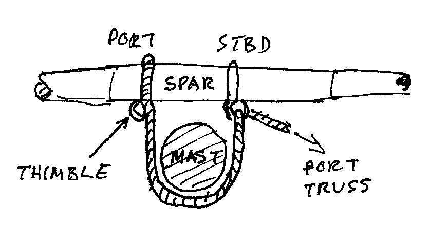
rraisley, There were trusses, truss pendants and truss parrals. Often just the term "truss" is used for all three. Trusses were ropes fastened to the center of spars and run down to deck to help lowering the yards. Trusses pendants were rope rigging attached to a spar to hold it against the mast. Typically the spar was suspended from the mast with a rope sling that went over the cross trees and around the mast. On later ships an iron assembly supported the spar, at least the heavier lower spars. The rope slings supported the spar, but allowed it to push forward, swinging on the sling, when the wind was in the sail. The truss pendants held the spar to the mast and transferred the force of the wind to the mast, taking this load off the sling. There were two ropes, port and starboard. One end of the line was fastened around the yard to one side of the mast, looped around the mast and through a thimble secured in the line of the opposite truss where it was tied to the spar, and then the free end ran to a tackle. The opposite side truss was rigged the same way (see below). For smaller ships the free end ran down from the spar to a (luff) tackle on deck. On larger ships the free end ran up to a (luff) tackle attached to the trestletrees in the mast top. In either case both truss pendants were pulled taut to snug the ropes tight around the mast. Thus caused the force of the wind in the sail to be applied directly to the mast through the truss ropes. But when the spar was being rotated or raised/lowered the truss pendants were loosened. Here is a drawing of the sling and truss pendants on a smaller vessel (topsail schooner). In this case the truss pendants are run down from the spar to the tackle on deck. When the truss pendant are pulled tight they pull down on the spar in opposition to the sling. If they ran up to the mast top they would actually help support the spar and could actually be used to raise and lower the spar, although a separate halliard was normally used for this on heavier spars. Here is a quick and dirty top view sketch to show how the truss pendants fasten to the spar and around the mast. This shows the port truss pendant fastened around the spar, with a thimble looped into the rope. The rope then passes around the aft side of the mast to starboard and through the thimble in the starboard truss pendant rope. From the thimble it either runs down to the tackle on deck, or up to tackle attached to the trestletrees in the mast top. The starboard truss pendant rope is rigged the opposite way round, passing around the mast to port and through the port truss pendant thimble. The smaller/lighter topsail, topgallant and royal yards typically did not have truss pendants, although I suppose the topsail yards might have had them on very large ships. The topsail and topgallant yards usually had parrals, but the royals often did not. A truss parral was two ropes tied around the spar port and starboard like the two truss pendants with thimbles looped into the ropes, but without the pendants leading to tackles. A separate lanyard passed back and forth around the aft side of the mast and looped through the thimbles. When the lanyard was pulled tight and secured it worked like a parral. Wolfram Zu Mondfeld's "Historic Ship Models" (Sterling Publishing Co., Inc, New York, 1989) is an excellent general resource for the parts and construction of sailing ships. On page 312 he describes truss pendants. James Lees' "The Masting and Rigging of English Ships of War 1625 - 1860" (Naval Institute Press, Conway Maritime Press Limited, 1990) tells everything you ever wanted to know (and a lot more) about the rigging of English ships. Hope this helps.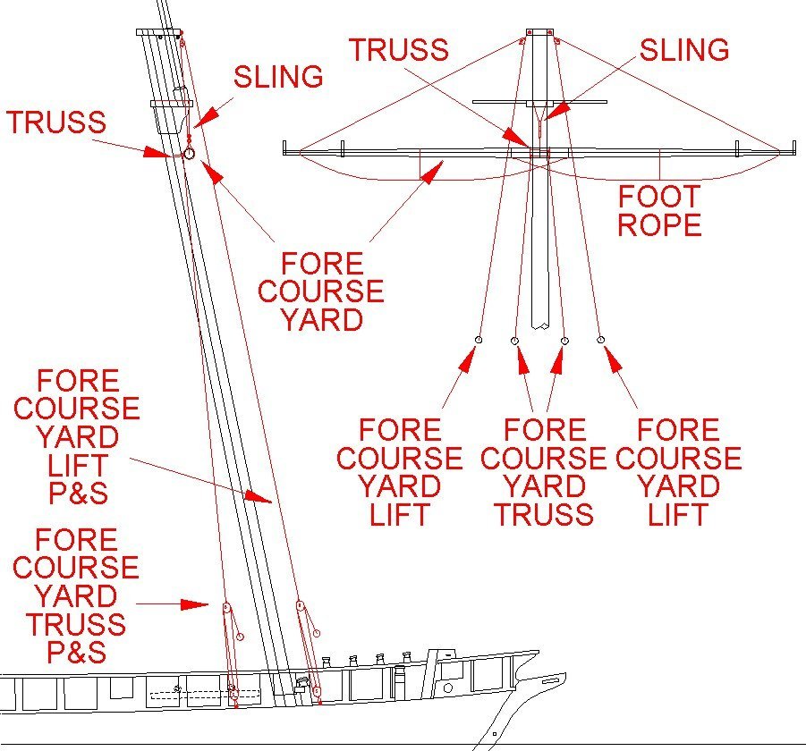
-
How to Make Mast Straps
Dr PR replied to rraisley's topic in Painting, finishing and weathering products and techniques
Kieth, I have used 3M masking tape for decades. The older stuff "dries" and becomes very brittle. The adhesive fails and the paper flakes off after 20-30 years, leaving a crust of adhesive on the surface. I don't know if the newer tape is any better. -
Lateen yards – inside or outside of the shrouds?
Dr PR replied to catopower's topic in Masting, rigging and sails
This thread has been very informative. I especially thank Cristiano for his drawings. I have know of the existence of latin (lateen) sails for decades, but never made a serious effort to learn how they were worked. Years ago I read a poorly worded description that said when the vessel tacked the lower end of the spar was held in place on deck and the spar (and sail) was lifted over the top of the mast! Or at least that is the way I interpreted the wording, and it made no sense at all! How are you supposed to lift something over the top of the mast? Use a sky hook?? Now I see how the sail and spar are swung around the mast, and it really is quite simple. A small crew can handle it. Thanks to everyone for clearing this up.- 14 replies
-
- 2
-

-
- lateen rig
- washington galley
- (and 1 more)
-
manic, Don't underrate first efforts. There is a learning curve, and getting other modeler's comments really helps. But something newbies often don't realize is that their "dumb" question sometimes cause the old-timers to stop and think. And the comments often reveal a multitude of ways to do the same basic things. Maybe there is a better or easier way than what the experienced modelers have been doing. There are no "dumb" questions, but sometimes the answers make you wonder!
-
turangi, I can't imagine Hong Kong without junks! There were dozens in the harbor at any time in the '70s, and thousands in the typhoon shelters (Aberdeen, etc.).
-
What does it sound like to be inside a XVIII century sailing ship?
Dr PR replied to Sperry's topic in Nautical/Naval History
My first ship was a wooden minesweeper USS Cape MSI-2. In port, with the engines off, I could hear the lapping of the small waves against the hull. But it was a pretty low sound and things like generators and fans/vent ducts would drown it out. You could hear some things going on topside (like holystoning) but I don't recall footsteps. Like Gary said, in heavy seas you can hear (and feel) waves slamming against the hull. And as he said, ships do flex a lot, so there were a lot of creaking sounds. I never tried hanging over the bow to listen to the bow cutting the waves. The ship's top speed was 13 knots with a tail wind so it wasn't cutting through the water very fast. On the cruiser I was on I did occasionally hang over the bow and on calm days the stem made a hissing sound as it sliced through the water. I did sail on a square-rigger once (Lady Washington) and a thing I noticed was that after we left harbor under power (against the tide and wind) and were at sea, when they shut off the engine it seemed to be very quiet. The engine wasn't loud, only a low hum, but under sail in calm seas it was very quiet. Just the low sound of the wind in the sails and ringing. And a bit of creaking as the ship rolled and strains changed on the rigging. -
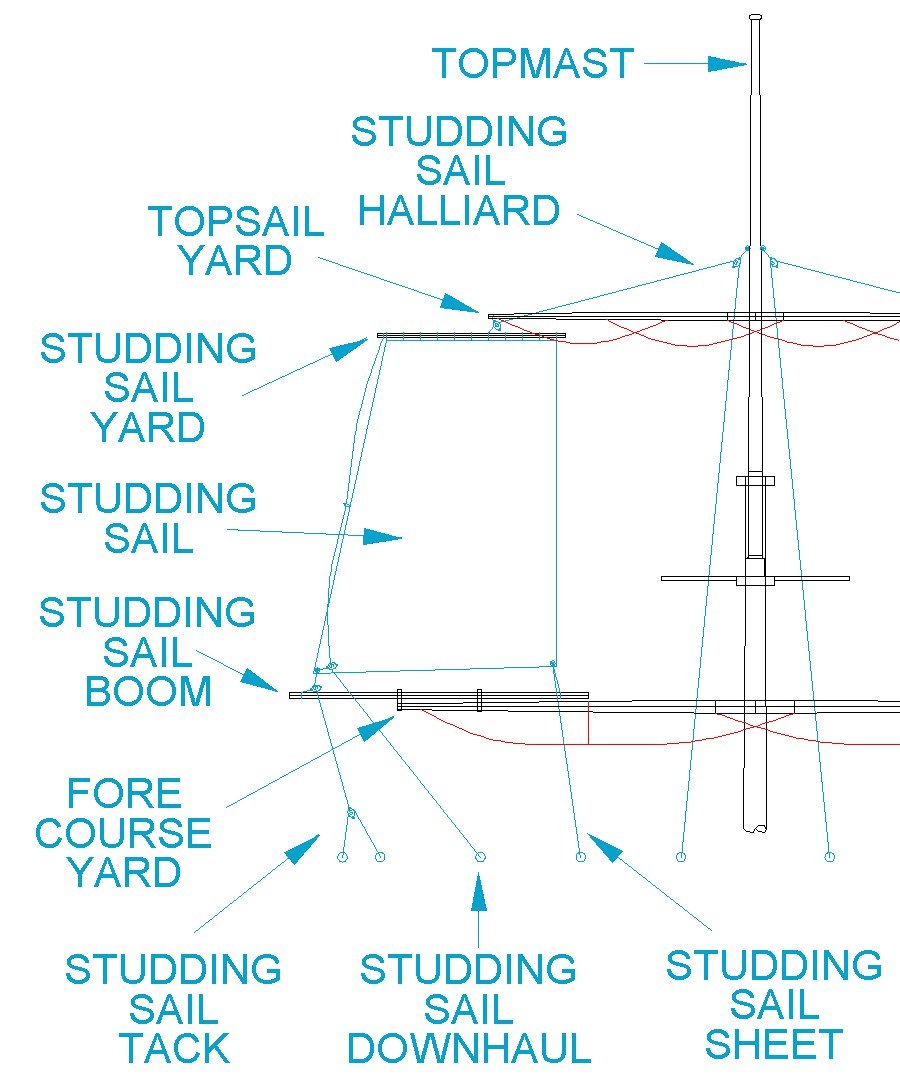
rraisley, "Loose footed" means the foot (bottom side) of the sail is not laced to a yard, spar or boom. The two "cringles" allamyed refers to are rope loops at the lower corners of the sails where the handling lines are attached (tacks and sheets). Typically stunsails were laced to a stunsail yard at the top and loose footed at the bottom. Stunsail booms were attached to the regular yards, sometimes on top, sometimes below, and sometimes forward of the yard, depending upon the country, period and whether it was a naval ship or merchant ship (nothing about sailing ship rigging is simple one size fits all). A halliard ran through a block at the end of the stunsail boom or upper yard, through a block at the mast and down, and was used to haul up (lift) the stunsail yard . The lower outer corner (tack) of the upper sunsails ran through a block at the end of the sunsail boom on the yard below and then to a purchase below. The lower inner corner or sheet was attached to the inboard end of the lower boom and then ran down below. The downhaul line was attached to the stunsail yard at the top of the sail, ran down through a block at the lower outboard corner and then down to below. It was used to pull down the sunsail yard and sail. Depending upon how high up in the rigging the stunsail was set these lines either terminated at the lower mast top or at purchases on deck. Stunsails on the course (lowest and largest square sail on the mast) were hauled up to the end of the stunsail boom with the halliard as shown for other stunsails. However the lower outboard tack ran to a block at the end of a stunsail boom rigged to the side of the hull (not shown), usually at the channels where the shroud deadeyes were attached. The tack then lead inboard. The sheet ran inboard to spread the bottom of the sail. I have been wading through rigging plans for topsail schooners and have posted sail diagrams, definitions and some other information here: https://modelshipworld.com/topic/25679-topsail-schooner-sail-plans-and-rigging/?do=findComment&comment=787759 It is focused on topsail schooners but there is a discussion and drawings of stunsails that you might find useful. There are also general diagrams of sails and rigging and explanations of terms. Since you are making a model of the HMS Victory you would do well to get a copy of "The Masting and Rigging of English Ships of War 1625-1860," James Lees, Naval Institute Press, Conway Maritime Press Ltd., London, 1990. It is a very detailed book, although it can be frustrating because the author often uses undefined terms and assumes the reader already is familiar with the subject. Another very useful book for the ship modeler is Wolfram zu Mondfeld's "Historic Ship Models," Sterling Publishing Co., New York, 1989. It is a more general book about all aspects of sailing ship models but it has a wealth of knowledge and definitions of many of the obscure nautical terms relevant to wooded ship construction.

-
Topsail schooner sail plans and rigging
Dr PR replied to Dr PR's topic in Masting, rigging and sails
I use an inexpensive CAD program (DesignCAD 3D Max) to create the 2D and 3D drawings and produce image files. Sometimes I edit the images in a photo editing program (Photoshop) to add or remove details, text, etc., and to crop and resize images.- 104 replies
-
- 3
-
-
- schooner rigging
- Topsail schooner
- (and 1 more)
-
I made "cut" splices for the cascobels on the cannons on my current build. It took some research and a few attempts to find a way that worked well. I describe it in this post: Note: If for some reason for me the Forum refuses to use the correct link and this link opens at the first post go to the second page and scroll down to post #59. https://modelshipworld.com/topic/19611-albatros-by-dr-pr-mantua-scale-148-revenue-cutter-kitbash-about-1815/?do=findComment&comment=650378
-
Jud, Thanks. You are correct that the anchor was not let go from the cat hook! My error! Lever/Blunt "Young Sea Officer's Sheet Anchor" doesn't describe letting go the anchor. However, it says that when the anchor was catted a rope stopper that was attached on one end to the cathead was looped through the anchor ring and then the free end was taken round a cleat on the cathead and hauled taut, and the end secured to a timber head and stopped. To drop the anchor it was lowered until it is hanging from the cathead by the stopper. The cat tackle could be used to carry the ring while the crown end is being lowered. Then the cat tackle would be slacked to let the stopper hold the anchor. The tackle would be tied back to clear the anchor. To let go the anchor the stopper was freed from the timberhead and allowed to slip off the cleat, allowing the anchor to drop. I will correct the original post. Of course, like everything else in the construction, rigging and operation of wooden sailing ships there was no single "correct" way to do things. There were different techniques used in different parts of the world and at different times. I do not know when pelican hooks were introduced, but I have read somewhere there was at least one other quick release "hook" in use before the pelican hook. I am familiar with modern (20th century) anchor handling: https://www.okieboat.com/Free steaming.html
- 24 replies
-
- 2
-
-
- anchor handling
- schooner
- (and 1 more)
-
Topsail schooner sail plans and rigging
Dr PR replied to Dr PR's topic in Masting, rigging and sails
Marcus, Thanks. But I am not an "expert!" I am a student and this is all a learning exercise. Keep that in mind. I'm sure others will find faults in what I have written and hopefully provide corrections. And as I have said many times, there was no one "correct" way to rig any vessel. There are a lot of exceptions to these rules! The spreadsheets are mainly for schooners and do not include everything about full ship rigging mentioned in Lees and Mondfeld.- 104 replies
-
- 2
-

-
-
- schooner rigging
- Topsail schooner
- (and 1 more)
-
Topsail schooner sail plans and rigging
Dr PR replied to Dr PR's topic in Masting, rigging and sails
Here is an updated version of the spreadsheet with the rigging definitions drawing embedded in the spreadsheet. Mast spar and rigging calculations.xlsx- 104 replies
-
- 6
-
-
-
- schooner rigging
- Topsail schooner
- (and 1 more)
-
Vince, Thanks for the reference. I'll see if I can find a copy.
- 24 replies
-
- 1
-
-
- anchor handling
- schooner
- (and 1 more)
-
Topsail schooner sail plans and rigging
Dr PR replied to Dr PR's topic in Masting, rigging and sails
George, Good idea. I didn't think of putting a picture in the spreadsheet.- 104 replies
-
- 1
-
-
- schooner rigging
- Topsail schooner
- (and 1 more)
-
Topsail schooner sail plans and rigging
Dr PR replied to Dr PR's topic in Masting, rigging and sails
Bob, Thanks. The Lady Washington had swivel gun mounts at several points along the sides. I suspect the two guns were mounted on the stern for show while the ship was taking tourists for a ride. People weren't allowed aft of the binnacle while the ship was sailing to avoid the swing of the tiller and the boom rigging. No swivels were mounted forward where the passengers were milling around. They were also doing "combat" excursions with the Hawaiian Chieftain at that time. They fired the guns on those excursions.- 104 replies
-
- 2
-
-
- schooner rigging
- Topsail schooner
- (and 1 more)
-
Topsail schooner sail plans and rigging
Dr PR replied to Dr PR's topic in Masting, rigging and sails
Here is my latest spreadsheet for calculating just about everything for masting and rigging. I have modified it to allow you to enter your model's scale to calculate the final values. And then the spreadsheet can calculate the number of packages of Syren rope and blocks you need and total the final price! (Prices as of 28 February 2021) Mast spar and rigging calculations.xlsx- 104 replies
-
- 6
-
-
-
- schooner rigging
- Topsail schooner
- (and 1 more)
-
Formula for the thickness of rope on any scale ship
Dr PR replied to flying_dutchman2's topic in Masting, rigging and sails
Note: I have updated the spreadsheet to allow you to enter your model's scale for the final calculations. Mast spar and rigging calculations.xlsx -
Formula for the thickness of rope on any scale ship
Dr PR replied to flying_dutchman2's topic in Masting, rigging and sails
I have been puzzling over rigging dimensions also. I read every reference I could find and entered all the formulas into a spreadsheet. Basically all rigging diameter is based upon the mast diameter. For the lower mast this is the diameter at the partners. This diameter is almost always calculated relative to the ship's beam (widest part of the hull). From the mast diameter the circumference of the main stay is calculated, and almost all other rigging dimensions are based upon the size of the main stay. Mondfeld's calculations are in error as pointed out above. The main stay circumference is 0.166 times the mast diameter, or 16.6% of the mast diameter. This number agrees closely with Lees and other references that I have found. But the common rigging dimensions given in period references are for the circumference of the rope, not the diameter! But all the thread and scale rope is measured by diameter. So you have to divide the circumference by pi (3.14159) to get the diameter. To simplify all of this I have created an Excel spreadsheet that includes the formulas from Lees supplemented by Mondfeld's formulas. Just enter the model's main mast diameter into the green cell (C3) and all the circumferences and diameters will be calculated automatically. If you don't use spreadsheets I have included a PDF "print" of the spreadsheet that shows all of the formulas and gives example dimensions for a topsail schooner with a 20 foot beam. CAUTION: Schooner masts and spars were smaller and lighter than those of square rigged ships. Schooners did not carry as heavy a load of sails and spars as a square rigger. The masts were typically 4/5 the diameter of square rigger's masts (this took a lot of reading through a lot of references to pin down the relationship!). Thank Harold Underhill for providing this insight. This is borne out by the actual mast dimensions recorded by Mariester in the early 1800s for real schooners as published in Chapelle's "The Baltimore Clipper." However, the relationships to main mast diameter and main stay circumference used in the spreadsheet is the same for about all ships. Small boats may be different. If you want a spreadsheet or PDF that lists all of the rules for mast and spar dimensions for square rigged ships and topsail schooners, with references and examples taken from period ships go to this link: ****************************************************************** Finally, I have attached the working spreadsheet for my current model, a topsail schooner with a 19.9 foot beam. It is tailored to my needs, but it can be used for any model with a few modifications. Note: The cells with green background require you to enter the appropriate values for your model. This spreadsheet includes calculations from Lees, Monfeld, Fincham, Rankine, Cock and Hedderewick (the last four were actual period ship designers) for just about everything - masts, spars, standing rigging and running rigging, for square riggers and schooners. Just enter the values in the green cells for things like the ship's beam, line of flotation, etc. If you don't understand the terminology or the measurement read through all of my thread linked to above. Note: Rankine, Cock and Hedderewick calculations are for topsail schooners. Lees and Mondfeld calculations are for square rigged ships. Columns A through W give calculations based upon each rule set, so you can see the differences and similarities. Columns X and Y contain the values I used for my model calculations. Just plug in the actual ship dimensions used for your your model Columns AB through AH calculate the dimensions to use in your model. Enter your model's scale "N" in cell AG2. Column AI then scales these to 1:N. Then using these values as references check them over to see if they really are about right for the model you are building. Then in columns BD and BE enter the actual scale dimensions of the model you are building for hull length on deck, hull length between perpendiculars and beam. Then presto! Column BH (green cells) lists the size of everything on the (schooner) model for spars, standing rigging and running rigging. If you are building a square rigger you may want to add additional calculations - based upon the original calculations at the left side of the spreadsheet - for extra spars, etc. Note: Mast and spar diameters are for the widest part only. You will have to figure out the taper and such. Then the spreadsheet calculates the appropriate block sizes to be used with the rigging diameters. I have listed all the dimensions of Syren's ropes, blocks and hearts so you can figure which are appropriate for your model, And then you can enter the appropriate rope diameter/lengths and figure how many packages of Chuck's rope you need in columns BQ through BV, and you can enter the type and number of blocks and packages of blocks you need. The costs of each package are listed so you can calculate the total order you need from Chuck in column BW. I hope you find this information useful. If you need anything else you are on your own. Mast spar and rigging calculations.xlsx -
Eric, I have been working on a topsail schooner model, and I have used the Dapper Tom kit instructions for reference for some parts. It is a beautiful ship (after all it is a schooner) and I will be following your build. I am especially interested in your plans to build it plank on bulkhead instead of using the solid hull in the kit. For you this is a bit premature, but I am to the point I need to start thinking about rigging the model. I found a lot of the information either confusing, inaccurate or incomplete, and the terminology impenetrable. After several months of scouring the literature I finally figured out how to rig topsail schooners - or maybe I should say many ways to rig topsail schooners. I decided to post the results of my investigations on the forum. Hope it is useful.
-
Navsoource has a lot of photos of CVEs, some showing details. https://www.navsource.org/archives/03idx.htm
- 25 replies
-
- 5
-
-
- Gambier Bay
- BlueJacket Shipcrafters
- (and 1 more)
-
Some wooden minesweeper hulls were planked in two layers. The inner layer was at 45 degrees to the horizontal/vertical and the outer layer was a more normal parallel to the horizontal. The frames were typical wooden ship design. I don't know if the deck planking was in two layers (I don't recall spending much time looking at the overhead), but the top layer was normal longitudinal planking.
-
There are always some tricky parts like this, and some always seem to be asking to be broken off! One thing you can try is using very fine wire or a wood sliver as a nail. Get a small drill bit slightly larger than the wire diameter. Use a pin vise to drill a hole through the piece and into the part it fastens to. Fill the holes with glue, position the part and insert the "nail." After the glue has set file the end of the nail flush with the surface.
-
Windjammer Wire Rope vs "Natural" Rope??
Dr PR replied to Ian_Grant's topic in Masting, rigging and sails
Ian, If Underhill's very detailed "Masting and Rigging" doesn't say how the wire running rigging was secured, who would? Actually, he does tell something about this in an off-hand way. Chapter IX "Use of Tables and Formulae" describes the dimensions of wire running rigging, so it is clear he is talking about wire rope. Then in Appendix III and Appendix IV he lists the rigging for a full rigged ship, with line numbers corresponding to the folding plate No. 51 Belaying Pin Layout for a Full Rigged Ship. Most of the lines run to pin rails and are labeled "BP" (belaying pin). So at least we know that the wire rope was secured to belaying pins in some manner. I hope someone knows for certain how this was done! **** EDIT: Bob and Jim posted while I was making my reply. Thanks! Bob is certainly right about the broken wire ends and how you don't handle wire rope with your bare hands! The same is true for spring-lay nylon ropes wound with some metal strands and other nylon strands. They are easier to handle, and the wire prevents the nylon from stretching. But the "meat hooks" can still get you! -
In the picture of the deck house (engineering space vents) in post #484, what are the things on either side just above deck level? Air filters? Rope spools? By the way, I was looking back through this thread and saw the picture of Khrushchev/Brezhnev 56 Chevy Bel Air (a Khrushchevy?). I drove one just like that (same color) to college in my freshman year (1963)!
-
Very nice (as usual)! That is a very simple - if tedious - method to make the chain. Using photoguestimation based upon a wire diameter of 0.8 mm I calculate the links to be 5.4 mm x 3.4 mm (0.21" x 0.13"). I don't know if I want to try it for my 1:96 OK City build. Wire diameter would be about 0.6 mm (0.26") and the links about 3.96 mm (0.156") long. I have the soldering skill but I don't know if I have the patience!