


Dr PR
-
Posts
2,401 -
Joined
-
Last visited
Content Type
Profiles
Forums
Gallery
Events
Everything posted by Dr PR
-
 In 20th century US Navy ship design: "Camber" is the transverse (port to starboard) curvature of large weather decks, highest along the centerline and lower at deck edges. "Sheer" is the lengthwise curvature of the large weather decks, typically highest at bow and stern. Not all weather decks had camber or sheer. Some had camber but no sheer and smaller decks typically had neither. I'm sure the terminology has changed with time and coountry, and even different locations within a country. **** As far as the hatch gratings go, I suspect it was the larger, fancier ships that had the curved gratings. Smaller and less expensive vessels probably had flat gratings, especially merchant vessels. Flat gratings would be easier and cheaper to build.
 -
JD, I found the definitions of "molded size" and "sided size" confusing. Your drawing shows it nicely. The following books use this terminology, but the descriptions are less than perfectly clear: Planking Techniques for Model Ship Building (Donald Dressel, TAB Books, 1988, page 26. The Elements of Wood Ship Construction, W. H. Curtis, McGraw Hill Book Company, 1918, page 27 (available as PDF on line). How Wooden Ships Are Built, H. Cole Estep, The Penton Publishing Company, 1918, page 44 (available as PDF on line). Wooden Ship Building, Charles Desmond, The Rudder Publishing Company, 1919 (available as PDF on line), page 53, Figure 41 has a drawing similar to yours, and page 52 has clear definitions. One of the things that confused me is that "molded dimensions" of the hull are to the outer surface of the frames, whereas the "molded size" is the transverse width of the frame at any place along the length of the frame, varying from widest at the keel and tapering to narrowest at the main deck. The outer outline (the molded dimension) of the frame was drawn on the mold loft floor. Then the line of the inner surface of the frame was created by passing through points at the desired "molded size" width along the frame. On steel hulled naval vessels the molded dimension is to the outside of the frame, or the inside of the hull plating (Ship Structure and Blueprint Reading, H. L. Heed, Cornell Maritime Press, 1942, page 166). I occasionally see erroneous statements saying the the molded dimension is to the outside of the planking or plating. But on all but the largest scale models the difference may be no more than the thickness of a layer of paint. I mention this in case other readers might find "molded dimensions" and "molded size" confusing. They aren't the same thing!
-
Mike, I have seen the double blocks idea used. But you want the sheet to come down from the upper block to a fastening on deck or on the bulwark. So just invert the blocks - the fixed end of the line would be on the upper block that is attached to the backstay. A similar rig was used for loading tackles (burtons). Some schooners used ordinary deadeyes for the backstays.
-
Bruce, Sounds like very good advice to me. Davy, Think of it this way - overcoming difficulties builds character. At least that's what they tell the Marines.
-
German-English translation is also "tail blocks." Not much help. But your drawing Figure 10 shows gun port cill or rebate and a 1 x 3 mm strip could be used for these. The rebate is what the port lid/door closed against, and ports often had this framing on all sides for better water seals. It is similar to the molding in a door frame that the door shuts against. The guns were run out against the lower cill before firing. Sometimes there was an additional block or bumper that the gun carriage contacted to set the firing position (battery).
-
Richard, I am glad you are making progress! You aren't the only slow builder. I haven't posted anything on my revenue cutter build log for a long time either. But I have been doing a lot of research on masting, rigging and sails. I have been giving some thought to the anchor handling. I suspect merchant schooners may have used some form of windlass to raise the anchor because they had small crews and plenty of deck space. But naval vessels had larger crews, and a lot more clutter on deck (cannons, etc.) so there wasn't much room for a windlass. Larger naval schooners seem to have used a capstan mounted aft. A continuous loop messenger line ran from the windlass forward to the fore mast and back to the windlass. The messenger was tied to the anchor cable. Turning the windlass pulled the messenger and cable aft, where the cable was lowered into the cable tiers. The cable was lashed to the messenger forward again and the capstan continued to pull it back, hauling in more cable. On smaller schooners, with lighter anchors, a pair of block and tackle rigs attached to strong points on the deck aft served as messengers. One rig would be used to drag the anchor cable aft until it was two blocked. Then the second would be lashed to the cable to continue the pull, while the first tackle was run back out. Using these alternate tackles the anchor was hoisted. For small vessels this didn't require deck space for a capstan or windlass. The cathead tackle was used to raise the anchor, and tackle on a portable fishing boom was used to raise (fish) the flukes to the deck or rail. Then the cable could be released from the anchor and stowed below deck in the cable tier. I am planning on modeling the fishing boom raising the anchor on my model.
- 78 replies
-
- 1
-

-
- dallas
- artesania latina
- (and 1 more)
-
Photos of 19th century gun carriage (from coastal fort?)
Dr PR replied to Louie da fly's topic in Nautical/Naval History
Pat, I was referring to all pivot/swivel guns in general, as used on ships in many navies. The larger guns definitely did have rollers that ran in tracks - there are numerous photos of these. They were mostly mid to late 1800s. Smaller guns may not have had rollers, but just slid on pads on the underside of the slide that ran on tracks on the deck. -
Photos of 19th century gun carriage (from coastal fort?)
Dr PR replied to Louie da fly's topic in Nautical/Naval History
It is interesting that it has wheels on both ends of the slide. It must have run in circular tracks, or at least in arcs, to allow rotation for aiming. Shipboard pivot guns were very similar. They either had a pivot at the center of the slide and wheels/rollers on the ends that ran in a circular track, or had a pivot at one end with wheels at the other running in an arc track. Smaller guns might not have had wheels or rollers, but just had pads that rotated on greased tracks. -
Seats of Ease
Dr PR replied to TKAM's topic in Discussion for a Ship's Deck Furniture, Guns, boats and other Fittings
On some late 1800s and early 1900s American schooners there were two heads, port and starboard, just aft of the bow. They were enclosed in boxes placed along the bulwarks. To use them the lid was raised, and closed when not in use. Some schooners had such boxes port and starboard at the fantail. In at least one case (three masted lumber schooner Wawona) the heads were beneath a fo'c'sle deck above the main deck, and had a bulkhead at the aft end of the raised deck for some privacy. The attached photo shows one on the port side - the ship was in bad repair (and was scrapped) and the raised fo'c'sle deck is missing. But you can see one of the deck beams and the short bulkhead.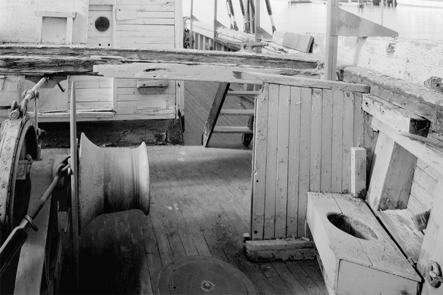
-
Mike, Everything I have read says that the diameter of the standing rigging was determined by the forces it was expected to withstand. Because the lowest sails were the largest, and these generated the largest forces on the lower masts, shrouds and stays for the lower masts were larger diameter than those for higher masts with smaller sails. SO yes, I do think that there were many sizes of rigging on real ships. But, schooners carried lighter masts and rigging that the large square riggers, and everything I have seen applies to the larger ships. So we really are left to guess about the topsail schooners. I think your rigging plan is fine. I am not sure what you mean by "collars." Are you referring to are the places where lines are fastened to masts with multiple turns around the mast> I have seen used where the line pulls directly out from the mast. Where the force on ht eline pulls down at a sharp angle "shoulders" were often used. These were either wooden pieces set into the mast that prevented the line from slipping down, or places where the dianeter of the mast was reduced to create the shoulder.
-
Mike, Here are some references for determining rigging sizes. I haven't yet sorted through them all to determine the rigging sizes for my model. George Biddlecomb's The Art of Rigging, page 117, has 38 pages of detailed information about rigging sizes for a wide variety of ships. The book also gives detailed instructions how to rig ships, spar dimensions, etc. James Lee's The Masting and Rigging of English Ships of War, page 185, describes the proportions of rigging to mast diameter. He says "With only a very few exceptions the sizes of both standing and running rigging can be worked out in relation to the size of the appropriate mast stay. The sizes of the stays can be ascertained by comparison with the size of the lower stays which in turn are given in ratio size of the lower masts." If the mast diameter = M Lower stays = 1/2 M Topmast stay = 1/2 the size of the lower stays = 1/4 M Topgallant stays = 1/2 the size of the topmast stays = 1/8 M and so on. He then goes on for five pages describing the remaining standing and running rigging relative to the stays. Harold Underhill's Masting and Rigging of the Clipper Ship and Ocean Carrier, Chapter X, (30 pages), page 244, gives tables and formulas for calculating mast, spar and rigging dimensions. Wolfram zu Mondfeld's Historic Ship Models, page 272, has a relatively short two page table of standing rigging sizes, and page 308 has a two page table of running rigging sizes. These tables are for different periods. They give rigging diameter relative to the thickness of the main stay, which he says is 0.166% of the diameter of the main mast at deck level. I think that must be a typo, maybe 16.6% or 1/6 the diameter of the mast. These proportions are for hemp rigging. Steel rigging was about 33% smaller diameter. If you aren't too anal about the rigging of your model zu Mondfeld's book is a very good reference. Also, note that the "authorities" don't agree about the sizes of rigging. For example, Lee says the lower stays are 1/2 the diameter of the lower masts - 50%. But zu Mondfeld says they are 16.6% the diameter of the mast. That is a huge difference! Biddlecombe and Underhill just list rigging sizes for "characteristic" vessel sizes. I have never seen a model or actual ship with stays half the diameter of the mast. However, stays are often doubled, so each strand need only be half the diameter of a single strand. And often an extra "preventer" is rigged just in case one of the stays fails. Keep in mind the amount of material in a line is not directly proportional to the diameter. The cross section area is = pi times the radius squared. So doubling the radius give four times the area. The diameters of the lines in a doubled stay would need to be only about 70% of the diameter of a single line for the stay. So, using Lee's figures, a single strand of a doubled stay would need be only 35% of the mast diameter. Still, that is more than twice the diameter zu Mondfeld gives! EDIT: Rope/cable sizes are given in circumference, not diameter. So a stay 1/2 the diameter of the mast has a circumference equal to half the diameter of the mast. Circumference == pi * diameter, so diameter = circumference/pi. Therefore Stay diameter = 0.5 * mast diameter/pi Also, Lloyd's of London produced tables of rigging sizes required for ships they would insure, and this strongly influenced the rigging on vessels. I don't have those tables, but they might be on line somewhere. One of these days, when I get caught up on a bunch of other projects, I will figure out the rigging layout and calculate the rigging sizes for my Baltimore clipper model.
-
Henry, Thanks for that critique. I have been puzzled by the rigging diagram in the Albatros kit. Some of it didn't make any sense to me (how can you have a fore royal stay when you don't have a royal?), so I decided to look elsewhere for topsail schooner rigging ideas. I really haven't put too much study time into it yet (way too many other things happening right now) so I haven't decided how I will rig my model. Reading thorough Chapelle's books, and especially The Baltimore Clipper and Fincham's rules and Marestier's dimensions of spars listed for real ships, it seems to me that the mast and spar dimensions in the Albatros kit are rather strange. The lower masts are too short for a Baltimore clipper, and the masts are not raked nearly enough. However, the British thought the masts and sails were too large on the American schooners and often cut the mast down a bit on American ships they captured. So the Mantua model may be based upon a British design for a topsail schooner - not exactly a Baltimore clipper, or "Goletta tipica di Baltimora" as the plans say. This is something for Mike to consider. Is he building a European topsail schooner or an American Baltimore clipper?
-
Mike, That plan is very familiar! You are building the Mantua Albatros kit - it is the same as the one I am working on, except I am kit bashing it as a revenue cutter with just the topsail and no topgallant. 1. By "lead over the fore stay" I mean that as the spars are lowered, with all the lines attached port and starboard, the spar and sail must be lowered to one side of the fore stay, say to port. In this case the port side lines will come down without fouling other lines, but the starboard side lines will hang over the fore stay. It will be necessary for the starboard lines to be managed to avoid tangling and fouling other lines. 2. "The braces would be draped over the main course spar." Sorry, I meant to say the fore course spar - the lowest and largest spar on the fore mast. These braces run through blocks at the main mast top and from there forward to the topsail spar on the fore mast. Then the spar is lowered the braces will come down on the fore course spar and then continue down as the topsail spar and sail are lowered to the deck. 3. I have been describing only a single topsail. This is the sail that hangs between the topsail yard and the fore course yard. Again, I have mistakenly called the fore course spar the "main" spar. I suppose the topsail and yard could just be lowered to the fore course yard and tied to it to reduce sail without dropping everything to the deck. If the ship also carried a fore topgallant above the fore topsail, handling it would have been similar to the handling of the topsail. The same is true for schooners that had square sails on the main mast. **** In post #66 in my thread for the Albatros kit I had a discussion with another fellow (Mike from t'north) who is building the same kit. He noted that there were many things that seemed way out of scale for a 1:40 scale kit. I agree, and we discussed options. The smaller cannons would have been 3 pounders, and the books say 6 pounders were about the smallest these schooners carried. The capstan would only be knee high at 1:40, and there were other peculiarities to the kit. All of the Baltimore clippers were built along the same lines, so the kit can be built at any scale between 1:40 and 1:96. 1:40 would be a very small schooner, and certainly would not have carried a topgallant, at least from what I have read in a number of books. On the other hand, 1:96 would be a huge topsail schooner, and more likely would have had three masts. I chose to work at 1:48. At that scale the cannons will pass for 6 pounders, and the larger gun could be a 12 pounder - which some Baltimore schooners carried. It would be a bit short for a "long tom" cannon. **** Henry (popeye2sea) makes a good point about the reef tackles and bowlines. They are shown in Petersson's drawings, which he made from a model of the Experiment in a Swedish museum. Presumably the model had all this rigging. But the topsails on schooners were much smaller than sails on larger square rigged ships, and the whole idea of the schooner rig was to reduce complexity. Looking at photos and drawings of topsail schooners I definitely do not see the bowlines. According to zu Mondfelds's Historic Ship Models bowlines were no longer used in the later 19th century. However I do see what appears to be reef tackles in photos of the Pride of Baltimore II. I also do not see lifts on the topsail yard. But the La Recouvrance does appear to have lifts. Lynx doesn't appear to have bowlines, reef tackles or lifts. There are a lot of variations in topsail schooner rigs. Some have a boom for the fore gaff sail and some have a boom for the fore staysail. Others have neither boom. Some have a fore gaff topsail and others have a main staysail. There are three versions of the main gaff topsail. There is a lot of variation on the flying jib - if the ship has one. I am beginning to think you can rig your model any way you want and there probably was/is a real schooner that was rigged that way at some time! I hope this helps. There is a lot of variety in the rigs of existing topsail schooners. I have been puzzling over the rigging for a few months now, trying to decide how I will rig my model.
-
Petersson shows the following rigging for the fore topsail. P/S = port and starboard. A. To control the yard: 1. The braces (P/S) are connected to the outboard ends of the yards and run to blocks at the main mast top (where the lower and upper masts double). From there they lead down to the deck. These are used to turn the spar to angle the sail to the wind. 2. Lifts (P/S) attach to the ends of the yards and run to a block at the fore mast top. From there they lead down to the deck. 3. The topsail halliard attaches to the center of the spar and runs through a sheave in the mast and then down to the deck. This is used to raise and lower the yard. B. To control the sail: 1. The cluelines (P/S) attach to a single block fastened to the topsail yard outboard of the spar center. Then they run through a single block attached to the lower corners of the sail and back up to the block on the topsail yard. From there they lead down to the deck. These can draw in the lower corners of the sail for reefing the sail. 2. The sheets (P/S) are attached to the lower corners of the sail. They lead through a sheave near the end of the fore course spar, from there to a block attached to the canter of the spar, and down to the deck. These are used to pull the corners of the sail out for setting the sail. They work opposite to the cluelines. 3. The buntlines (P/S) attach to the lower edge of the sail about 1/3 of the way in from the sail corners. They lead up to a single block attached to the topsail yard near the canter and then down to the deck. They are used to pull up the bottom edge of the sail for reefing. 4. The reef tackle (P/S) attaches to the outboard end of the topsail yard. From there it runs down to a single block attached to the outboard edge of the sail 1/4 to 1/3 of the way down to the lower corner of the sail. It runs through the block and back up to a sheave near the outboard end of the topsail spar, then over to a single block attached to the mast above the spar, and from there down to the deck. It is used to draw up the outer edges of the sail when the sail is reefed. 5. Bowlines (P/S) had bridles that attached to the outer edge of the sail at several places below the reef tackle. The bridles attached to lines that led down to single blocks on the bowsprit cap and then back to the deck. They were used to keep the upwind side of the sail extended when running close-hauled. **** That's 15 lines for a single topsail and yard. To my inexperienced eye it seems a bit unwieldy to lower the entire rig to the deck. Either the port or starboard lines would have to be lead over the fore stay and the braces would be draped over the main course spar. A lot of rope would be needed! But there is no reason why it wouldn't work. It would allow changing the sail without sending men aloft. The topsail spar and sail could be lowered to the main spar where the sail could be tied to the spar along with all lines, and then the bundle could be lowered to the deck. If anyone reading this actually has experience on a topsail schooner, please enlighten us to how it was actually done.
-
Caullking Planks
Dr PR replied to shortgrass's topic in Building, Framing, Planking and plating a ships hull and deck
Bob, Thanks for the details. I have the blueprints for the American Cleveland class cruisers, and the drawings for the wood deck have instructions for caulking the seams. They are pretty much what you just described, and the marine glue was supposed to be added to create a bead above the deck surface that overflowed the plank edges. There were plenty of men in the deck divisions to scrape and holystone the decks to bring the glue down even with the plank tops. They referred to "caulking" the groove with one thread of cotton and two of oakum pounded in, leaving a minimum 1/8" deep groove. Then they were "payed" with black marine glue that overran the seams by 3/16 inch. However, in another part of the drawing they also refer to the marine glue as "caulking compound." We replaced the wood deck on the OK City while I was aboard, but I really didn't pay much attention. We were spending 2/3 of our time at sea pumping bullets into the jungles in Viet Nam or trying to shoot down MiGs, and after six or eight weeks of one in three watches the last thing I wanted to do in port was stand around and watch shipyard workers replacing the decking! I do remember all the threaded studs welded to the metal deck to bolt down the wooden planks. You could stub your toe on those things and do a face plant if you didn't pay attention! -
Mike, Good question! I do not have a certain answer. Here is my best guess. With the hull length you gave - 65 feet - this is a relatively small topsail schooner, so the single sail and spar wouldn't be all that heavy. The rigging for the main topsail would be about the same as for the fore topsail, with the braces running forward to the fore mast top and then down to the deck. The main stays would present an obstacle for lowering the main topsail just as the fore stay was for the fore topsail. So I can't see why there would be much difference between the procedure or difficulty for raising and lowering either topsail. Of course, given the number of lines running to either of these sails, there would be plenty of opportunity for getting things fouled up. But with the proper rigging and experience it should be routine. Why would they go to the bother? I guess it was because it took fewer men to rig the sail and spar on the deck and then haul them aloft. I also think I read where it was a very quick way to put up the sail when the wind was right and get it back down when the high sail wasn't wanted/needed. On of the rather bizarre characteristics of the topsail schooners - especially the Baltimore clippers with their very large sail area - was nosing into a swell when hit from behind by a strong gust and suddenly plunging to the bottom. I have read two accounts of schooners with full sails set just diving into a wave and disappearing with all hands in a matter of seconds! When the Brits captured American Baltimore clippers they often reduced mast heights and sail areas because they thought the rig was too large for the relatively light hull. But this reduced speed, and that is what these ships were all about. When the British started increasing mast height and sail area on their topsail schooners to increase speed they lost some of them just like the American ships. In addition, there are accounts of schooners with the topsails set suddenly capsizing when hit by a strong gust broadside. There was a price to pay if the top hamper was too large. So it was very important to be able to get the top sails down in a hurry! The Baltimore clippers had the broadest beam forward near the fore mast, instead of midships like most other sailing ships. The reason was the additional weight of the topsail and rigging, and sometimes a larger diameter fore mast to support the larger rig. The broader the hull the more weight it could float. This put the center of gravity farther forward, and that probably contributed the the reduced stability.
-
Caullking Planks
Dr PR replied to shortgrass's topic in Building, Framing, Planking and plating a ships hull and deck
Bob, It was a mess! Note that I said I built the model (from a kit) about 50 years ago. It was the last deck that I calked with tar! As I recall I laid the planks and then ran a knife blade between them to create the gap for the grout. Then I heated the tar and rubbed the thick liquid into the grooves. And that left a lot of tar on the tops of the planks. After scraping the excess tar away I tried sanding the deck, but that just smeared the tar over the planks, so I had to scrape again. I didn't pack the grooves with cotton and oakum before applying the tar, so it isn't truly "authentic." The kit planks were a coarse grained wood - out of scale, but typical for kits of that period. And the caulk grooves were also too wide for scale. The "tar" was actually a mil-spec black marine glue. We just called it "tar" because it looked like tar. It has aged a bit now, with half a century of dust accumulated on the tar. -
Kieth, Wefalk's suggestion of "photo stacking" is a good way to get extremely good depth of field. I used it to make this picture: The distance from the tip of the bowsprit to the stern boat davits is 22 inches (56 centimeters) and the image is in sharp focus for the full length! I think there were 12 different images. I just focused first on the tip of the bowsprit, and then moved the focus in steps along the length of the ship for each successive picture. This was made indoors with rudimentary lighting. You get the best results with good lighting, but harsh lighting like direct sunlight will produce undesirable shadows. Cloudy bright or diffused light is best. The camera has to be mounted on a tripod and in the same position relative to the model for each shot. A high f-stop and good depth of field make better images. However, you can use low light and shallow depth of field and just take a lot of images with slightly different focuses. The separate images must be aligned and scaled before stacking.
-
Mike, Schooner rigs were not "normal" with respect to square sail rigs, and virtually every "how to" book focuses on square sail rigs. Most of what the normally referenced sail and rigging books describe just doesn't apply to schooners. Everything about the schooner rig evolved to require the minimum crew and a minimum number of men aloft. The ships often did not have ratlines, and when a man had to go aloft he was hoisted or climbed the gaff sail hoops. If you look at books on schooner rigs you will see that the fore/aft sails have minimal rigging. The masts also have just the basic shrouds and stays. There isn't a lot of rigging aloft to interfere with raising and lowering the upper yards. The lines for the jib and flying jib were usually attached to the fore mast above the spars for the top sail and topgallant. Only the fore stay was in the way of lifting and lowering the rigs. However, on larger ships the jib stay might be attached above the top yard and below the topgallant yard. I have seen descriptions of the top sail rigs, but very little on how they were handled. But just looking at how they are rigged you can see that they had to be maneuvered around the fore stays. The sheets, cluelines, reef tackle, braces, halliards, bowlines, buntlines and lifts would have to be rigged to the spars and sails on deck. Then the running ends would have to be led around the stays and shrouds or over the fore yard to avoid interference as the spar was lowered or hoisted. It sounds complicated, but if you think about it the process is no different from the procedure to replace a spar on a square rigger. But there were only one or two sails involved on topsail schooners, and they were much smaller than the sails on a square rigger, and the spars were much lighter. It appears to me that the lifts and braces bore the force of the wind on the sails. Because often there were no parrels the lifts pulled on the fore mast and the braces pulled on the main mast. In a similar way the course sheets transfer part of the force to the hull. However, on some rigs parrels were used for the top yard, but these were detached for raising and lowering the yards. Again, I recommend Petersson's Rigging Period Fore-and-Aft Craft as a reference for topsail schooner rigs. Also, you can find some descriptions of modern topsail schooner rigs and rigging practices on line.
-
I am searching for brass tube
Dr PR replied to Fresh water sailor's topic in Metal Work, Soldering and Metal Fittings
McMaster-Carr is an excellent source for tubing, sheet, special shapes, fasteners, materials, tools and much more: https://www.mcmaster.com/ The prices are usually better than hobby suppliers. -
Mike, A 65 foot Baltimore clipper would have a light rig. I am building a model of a topsail schooner from about 1815 that is 68 feet between perpendiculars, with six 6 pounders and a 12 pounder "long tom" pivot gun. I have been studying a number of references and have posted some of my results for masting here: Post #69 discusses the sails for a Baltimore clipper of this size. Most drawings of 60-70 foot topsail schooners show only a top sail. Larger ships had a topgallant, such as La Recourvance with an 82 foot hull has a topgallant. Belle Poule is about the same size but has only a topsail and no topgallant. Lynx, at 72 feet between perpendiculars, has only a topsail. From what I have read parrals weren't used on the topsail and topgallant yards. These yards were lowered to the deck to work the sails. That way no one had to go aloft. Then they were hauled up again. So the yards were not attached directly to the masts in any way. The fore yard was attached to the fore top. I guess it was rarely, if ever, lowered. I hope you post your work. I am very interested in these topsail schooners.
-
Caullking Planks
Dr PR replied to shortgrass's topic in Building, Framing, Planking and plating a ships hull and deck
Dave, I recently planked a hull with nibs and caulking. I did some experiments on six different methods of "caulking" in the link below. I chose to use black construction paper. Post #25 shows the results. I was very happy with the results. I served on two ships with teak decks (a minesweeper and a cruiser). On both ships the decks were holystoned and bleached so the wood was very light and the grout was very black. But I have also seen older ships (in museums) where the grout stood proud of the surface a bit and was weathered gray and the wood was also weathered gray. On both ships I served on the grout was 3/8 inch wide. On the 1:48 scale model linked to above I chose a black craft paper that was 3/8" scale thick. However, the planks supplied with the kit were far too wide to be realistic (about 9.5 scale inches). After the deck was scraped to remove paper rising above the planks, sanded to even up plank height (the planks supplied with the kit were a consistent 5 mm wide but varied in thickness from 0.75 mm to 1.5 mm), polished with 0000 steel wool and finished with clear lacquer the grout lines were very narrow and the color was a dark gray. If you really want to get "realistic" grout you can do what I did on an earlier model. We reworked the decks on the minesweeper and I saved some of the tar that was used for the grout. Then on my next model I used the tar for the grout between the planks! Here is a picture of the deck from that model I made about 50 years ago.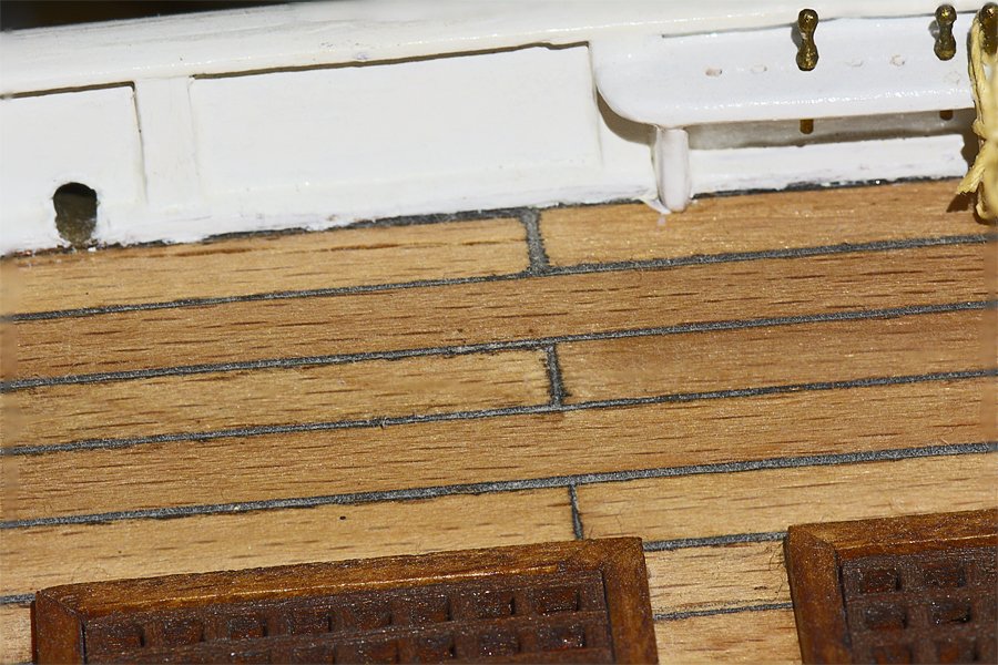
-
Smaller topsail schooners (50-80 feet between perpendiculars) usually had one top sail. Longer schooners had a top sail and topgallant, or lower and upper top sails, depending upon the period. The fore yards were supported by slings attached to the fore top, and controlled with braces and lifts. The highest yards usually were supported only by halliards and controlled with braces and lifts, with no parrels or attachments to the mast. They were lowered to the deck for rigging the sails and lines, and then hoisted aloft. This way no one had to go aloft to raise the sails, and you often see drawings and plans with no rat lines on the stays. The gaff topsails were rigged in a similar manner, supported only by halliards and sheets, often with a top spar (gunter) that was hoisted in a similar manner to top sail and topgallant yards. Again, the sails could be rigged on deck and then hoisted aloft. Some of the largest schooners (greater than 100-110 feet in length) had rigs more like the full rigged clipper ships of the mid 1800s. Of course, these are just general "rules" and different masters and owners had their own variations. And in addition the standard sails they had means of hanging a lot of additional canvas in studding sails, water sails, ringtails, staysails, gunter sails, courses, bonnets and drabblers. Howard Chapelle's The Baltimore Clipper is the best reference for these ships. Lennarth Petersson's Rigging Period Fore-and-Aft Craft is an excellent reference for rigging small to medium topsail schooners - Baltimore clippers. Harold Underhill's Masting and Rigging the Clipper Ship & Ocean Carrier is an excellent reference for mid to late 1800s clipper ships and coastal schooners, English style. But by then the design had evolved so everyone was building topsail schooners in more or less the same way. He provides very detailed drawings and descriptions for rigging these ships. I have a bunch of the other "standard" references for ship rigging, but most of what they say applies only to large square rigged vessels. Topsail schooners were a breed apart, with a rig that evolved for handling by very small crews. However, these references are handy for deciphering the nautical terminology. George W. Blunt's 1858 revision of Darcy Lever's 1808 The Young Sea Officer's Sheet Anchor described the American way of rigging ships in the early to mid 1800s. Again, it is mostly about square rigged ships, but it does describe how the lines were rigged and has quite a bit that applies to fore and aft rigs.
-
New Young Model Builder from Minnesota LOOKING FOR ADVICE
Dr PR replied to Kenna's topic in New member Introductions
Kenna (and Ron), I envy you! Your first build is always exciting and challenging. And I commend you for wanting to scratch build. When I was your age I didn't have the money for a wooden model kit, and the hobby shops in my home town didn't carry them anyway. This was decades before the Internet so scratch building was my only choice. I built a two foot long model of a Chris-Craft cabin cruiser, like a 40 foot real boat a friend of the family owned. I occasionally got to drive the real one, and loved the lines. I had no plans so I just winged it, and the model came out OK. It had a complete interior and even had motors (but no radio control) - I just swam along and turned it by hand. It wasn't very "accurate" but it was a lot of fun to build! Nothing like the quality of the scratch built beauties you see on the Forum, but I thought it was great, and that's what counts. Then I got bold and tried to model a schooner like I saw on a favorite TV show. Unfortunately, I knew nothing about sailing ship designs. I had built a bunch of plastic ship models, so my "schooner" hull was far too narrow, more the shape of a destroyer hull. The masts were too tall, and when I put it in the water it immediately capsized - "turned turtle." That was a disappointment! Eventually I hung a heavy weight from the keel but that acted as a sea anchor so it didn't "skim over the waves" like the schooner on TV. And it still floated with a sharp list to one side or the other. I gave up on the floating model and just sat it on a desk to look at. As a working model it was a failure, but I thought it was pretty. I tell you this because no one's first model, kit or scratch build, will be their best. But just building the kit you will learn the skills you need to do a better job. I have built several models from kits and from scratch since then, and I am much better now at researching the designs before I start. But I still have fond memories of those first scratch built attempts at wooden ship modeling. So I encourage you to dive in, and don't be too critical of your own work - even though you may be your own worst critic. What ever you build, be it a beauty or a beast, you will always remember it. And you will have the satisfaction of having built something! So remember to laugh at your mistakes and enjoy the experience. If you do, your next build will be much more enjoyable. And if you post your build here on the forum, other members will be a source of encouragement and advice.