Dr PR
-
Posts
2,471 -
Joined
-
Last visited
Content Type
Profiles
Forums
Gallery
Events
Everything posted by Dr PR
-
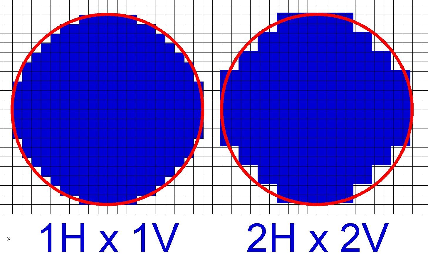
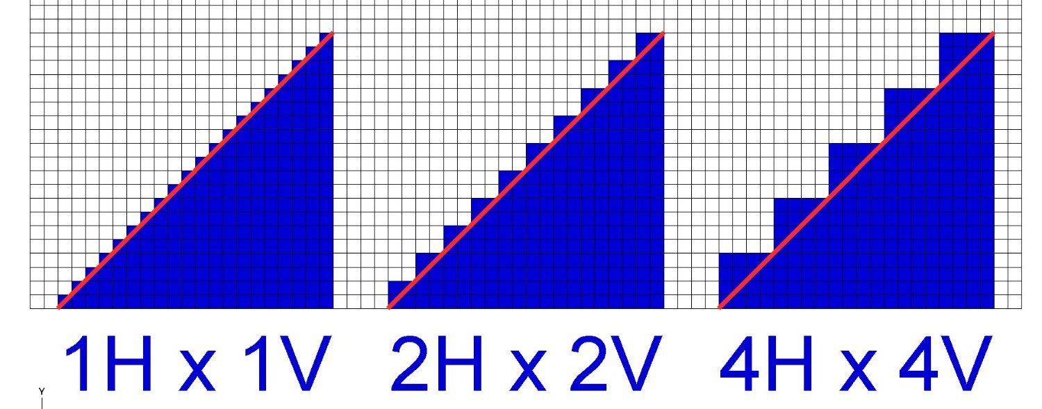
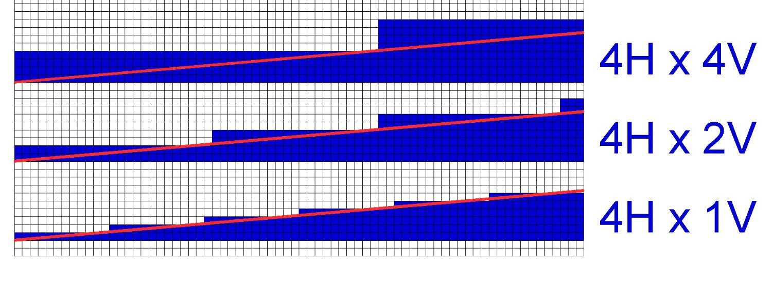
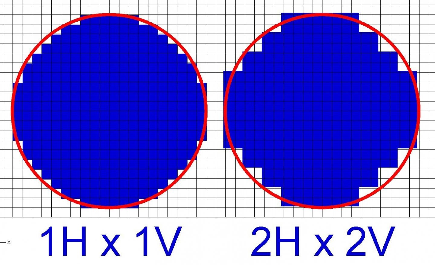
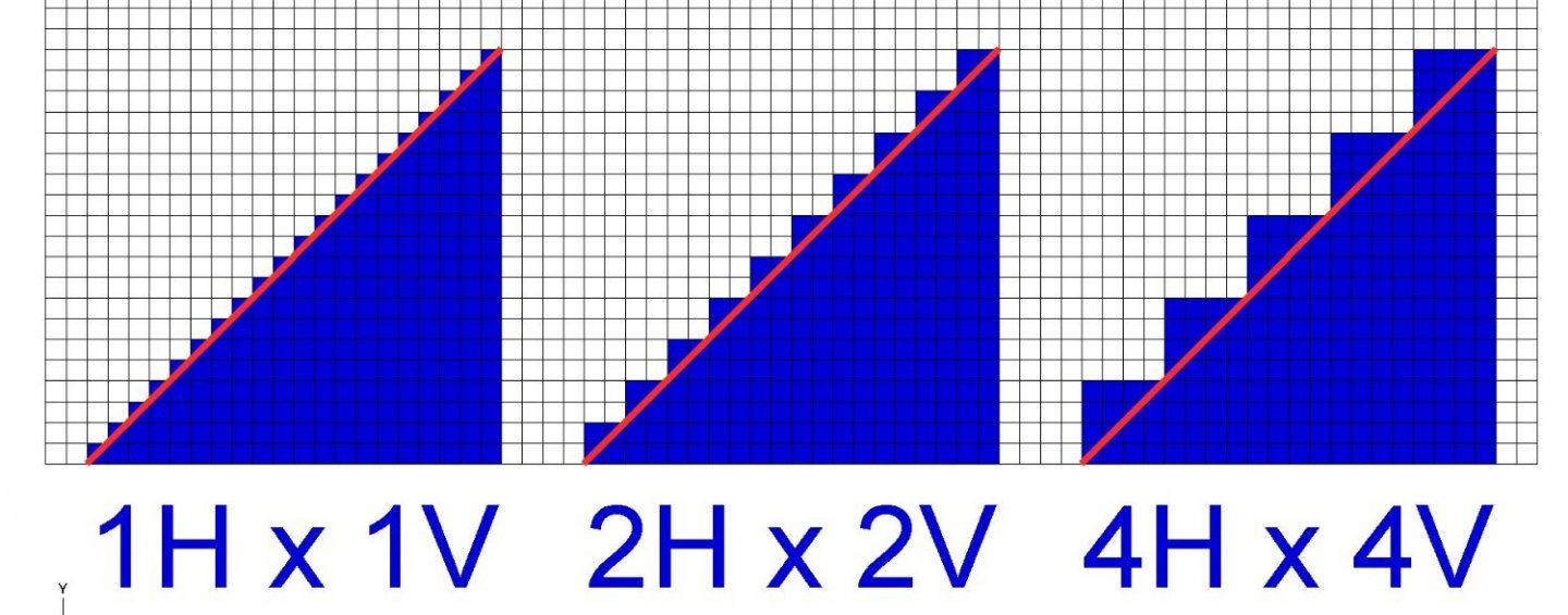
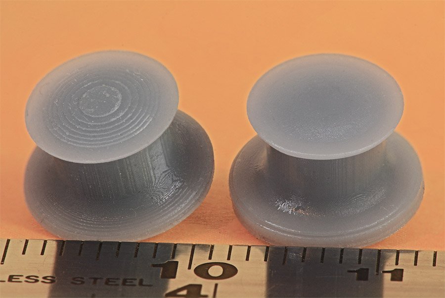
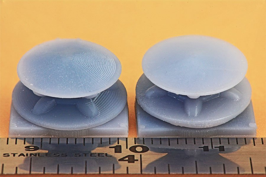
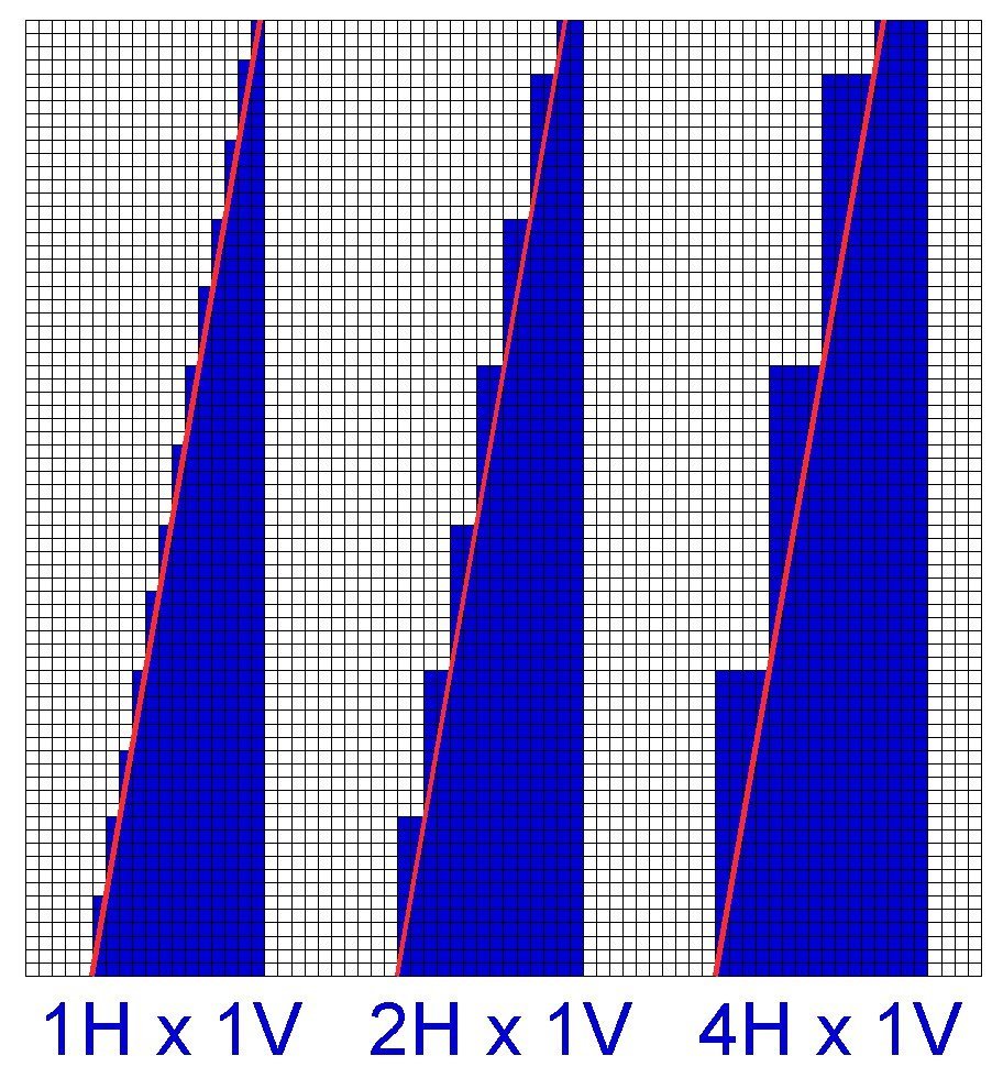
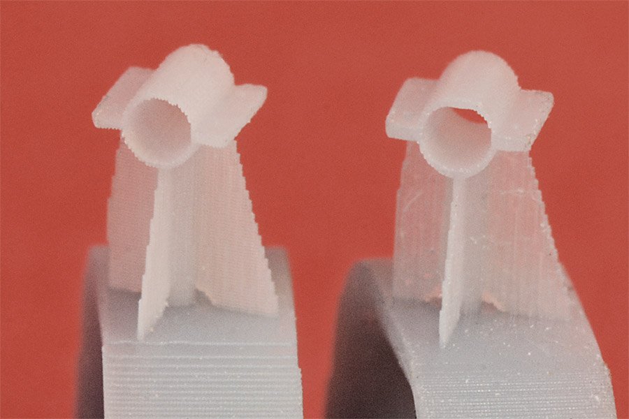
As I said earlier, I am a novice at 3D printing, having started after last Christmas when I received an Anycubic Photon Mono printer as a (totally unexpected) gift. The Admiral's youngest son gave it to me, and he readily admitted that he did it because he has one, and wanted me to figure out how to use it and be his tech support! I have been into digital photography for decades and had a pretty good idea about pixel density and image quality. But with 3D resin printing there is another dimension, the vertical step size. And there are a few complications due to this third dimension that I hadn't thought of and learned the hard way. First let's consider the basic 2D pixel size. This is what the LCD display produces, and is the fundamental limiting factor in print resolution or surface smoothness. You might think more pixels in the LCD display is better, and basically it is. But there is a catch. Larger displays tend to have more pixels, and they allow larger things to be printed. But more pixels does not automatically mean better resolution or smoother surfaces. Consider a 3" x 2" display with 100 pixels per inch (300 x 200 pixels). Each pixel is 0.01" x 0.01" (0.25 mm x 0.25 mm). Now imagine a 4" x 2.6" display with 100 pixels per inch. There are 1/3 more pixels but they are still the same size. It is the number of pixels per inch/cm that determines resolution, not display size. If you had a larger 4" x 2.6" display with the same 300 x x200 pixels, each pixels would be larger, and the resolution/surface smoothness would be less. On the Photon Mono the pixels are 0.05 mm x 0.05 mm and this determines the minimum horizontal resolution for the printer. Here is a picture showing how pixel size determines resolution: The "circle" on the left has pixels 1X the grid spacing, and the one on the left has pixels 2x the grid resolution, or an area 4 times as large as the one on the left. It is clear that the larger pixels cause larger "jaggies" than the smaller pixels. But it may not be obvious that the smoothness of vertical surfaces is limited by pixel size. If the circles are extruded (printed) vertically, the resulting cylinder on the right will have deeper grooves in the sides than the one on the left. So smaller is better, and this may be more important than the total number of pixels. Less obvious is the effect the vertical step size has on surface smoothness. Of course the smoothest surfaces are either perfectly horizontal or vertical flat surfaces. But with non horizontal or vertical surfaces things are different. The smoothest angled surface you can get is at a 45 degree angle to horizontal with the horizontal pixel width and vertical step size the same. Again, you can see the 1x pixel/steps create a "smoother" surface than the 2x and 4x pixel/step sizes, so again smaller pixels produce smoother surfaces. But not perfectly smooth because pixel size will always be finite, producing finite sized steps. So to get the smoothest angled surfaces the part should be oriented as close as possible to a 45 degree angle from horizontal. For the Photon Mono with 0.05 mm pixels the step size would be 0.05 mm. But this one to one pixel/step size smoothness rule applies only to 45 degree slopes. For shallower slopes the step size is all important for getting smooth surfaces. In this picture the red line is angled at 10 degrees from horizontal. The horizontal "pixel" size is 4x, and the vertical step size is 1x, 2x and 4x. Clearly the 1x vertical step size produces a "smoother" surface. It has more jaggies, but they are smaller. On the Photon Mono the minimum vertical step size is 0.01 mm (0.0039 inch), about the thickness of a sheet of printer paper. This isn't just a theoretical conclusion. Look at these pictures: In both images the capstan (above) and wildcat (below) were printed at 0.05 mm and 0.01 mm vertical steps. The 0.01 mm vertical step parts (right) are clearly smoother than the 0.05 mm parts (left). This is most apparent on the near horizontal surfaces. Of course, you can't get something for nothing. You have to print 5 times as many slices at 0.01 mm step size as with a 0.05 mm step size, and that takes 5X as long for the exposure process. However, as described below, this does not mean 5x as long total print times. Things aren't as simple for vertical surfaces. In these three examples the red line is angled 10 degrees from vertical and the vertical step size is the same, 1x. But you can see the surface smoothness is very different for the three examples. The vertical step size has no affect if it is smaller than the pixel dimension. The reason is simple - no matter what the vertical step size is, the horizontal "step" size is determined by the LCD pixel dimensions, and smaller pixels are better. You can print as many steps as you want (smaller or larger vertical step size) and the jaggies are still determined by which pixels are turned on or off in the LCD display. However, using vertical step sizes larger than the pixel dimensions will produce rougher surfaces. So for objects with vertical surfaces angled 45 degrees or greater from the horizontal you should use a step size equal to the pixel dimension. Again, this is not just a theoretical conclusion: Again, the chock on the left was printed with 0.05 mm vertical steps and the one on the right had 0.01 mm vertical steps. You can see the near horizontal surfaces are much smoother in the 0.01 mm print on the right, but the edges of the vertical supports are about the same roughness because the LCD pixel dimensions were the same. If you have mixed near horizontal and near vertical surfaces, use a smaller vertical step size to make the near horizontal surfaces smoother. There are a few more things to keep in mind. First is total print time. The actual exposure time for each "slice" is a fairly small part of the total print time. More time is spent raising and lowering the print stage. I have been using the recommended lift speed (4 mm/second) and retract speed (6 mm/second) for the Photon Mono. So for each slice that is printed 10 seconds expire while the stage is moving. I have used 5 second and 3 second exposure times for each slice. So the exposure time is only 1/3 to 1/4 of the total print time. Smaller step sizes do increase total print time, but not as much as you might think. Another thing to consider is the effect of exposure time on the surface smoothness of very small objects. This is tricky! The resin I have been using is the Anycubic Basic Grey. In quantity it looks opaque, but for very thin layers/slices like 0.01 mm it it translucent - some light passes through it. And this means that any resin that accumulates on top if thin horizontal surfaces may be exposed even if it isn't a part of the slice that is being printed. I have noticed that very thin horizontal cylindrical objects (0.05 mm or less) tend to print thicker in the vertical direction than in the horizontal with 5 second exposures. Reducing to 3 second exposures reduces this over thickness (the minimum recommended exposure of the Basic Gray resin for the Photon Mono is 2 seconds). A third thing to fiddle with are some "advanced" features in Chitubox. These are in the "Settings/Advanced" tab. The "Anti-aliasing Level" is an attempt to minimize the jaggies effect. It has three settings 2, 3 and 8 that cause the pixels at the edges of objects to be shades of grey instead of black or white. 2 is the grayest and 8 is just black and white. The result is that you get less exposure of the gray edge pixels than for the white interior pixels. This seems to harden less resin on these outer surfaces and it pools in the grooves, making them less noticeable. But this is a very subjective thing! The other "Advanced Tab" feature is "Grey Level." It ranges from 1 to 8, and as far as I can tell it works just like the "Anti-aliasing Level." Step 1 is the grayest and step 8 is black and white. I have been experimenting with 3 second exposure times, 0.03 mm vertical step size and an Anti-aliasing level = 2 and Grey Level = 4. There is also an "Image Blur" option, with "Image Blur Pixel" sizes of 2, 3 and 4. $ blurs the edges of the surfaces the most and 2 the least. I haven't experimented with this yet. Finally, exposure time affects the hardness of the printed slices, and that affects the success or failure of your prints. That is the subject of the next post.

-
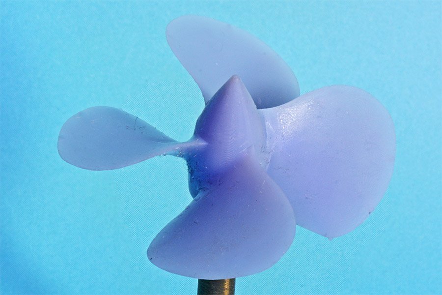
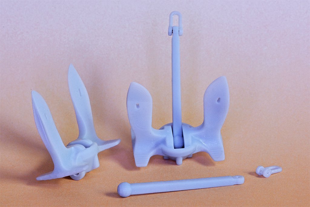
I have been working with an Anycubic Photon Mono since Christmas and thought I would pass along a few things I have learned. I have used the CAD program "DesignCAD" since 1988. It is a surface/mesh program with true 3D solid capability, but most of what I have done has been just planes and meshes (grids) that have zero thickness. I combine these to create the 3D object but they often have leaks and are unsuitable for 3D printing without some "repair." Microsoft's "3D Builder" program is free for Windows 10/11 and does (almost) perfect repairs. The only catch is that it will place a surface over any closed opening in a single plane/grid. So I have to be sure I create separate surfaces around holes. I don't know if this is a requirement for STL files that some programs do automatically. It is not a problem for solids that I have "drilled" by subtracting a tool solid, so it is just a problem with the way I made some of the objects. I use the Chitubox slicer program, and it does a pretty good job with the default settings. More about this in another post. Here is a link to a 3D model I created. I am now printing many of the parts you see on this ship. https://modelshipworld.com/topic/19321-uss-oklahoma-city-clg-5-1971-3d-cad-model/?do=findComment&comment=590228 https://www.okieboat.com/CAD model.html I started a 1:96 scale physical model about 16 years ago but stopped until I finished the CAD model. I have started the build again and am 3D printing parts for the model. https://www.okieboat.com/Ship model page.html I have been amazed at the resolution I can get with the Photon Mono printer! Here are a couple of examples of 1:96 scale parts. These are straight off the printer (after curing) without any touch-up. The CAD model was created 1:1 scale from the original blueprints, including all the proportional angles and dimensions of the real thing. At 1:96 scale the blades are only 0.25 mm (0.0095 inch) thick. This is far too thin to try to machine and much too thin to try to cast. But I just scaled the file to 1:96 and printed it! The diameter of the propeller is 1.46 inches (37 mm). They printed perfectly the first time using the default supports added by Chitubox. For this print I used a vertical step of 0.01 mm, 0r 0.0039 inches. The surfaces are smooth to the naked eye, but with 10X magnification I can detect a hint of the digital "jaggies." The anchor was also created 1:1 in CAD from Navy drawings. It is made up of dozens of individual complex curve surfaces. I figured if this would print anything would! It also came out perfect the first time! This was a 0.05 mm vertical step and some slight jaggies are visible on the bottom surfaces of the flukes. So this was the result of my first attempts to print with this printer. It just seemed too easy, especially since I already had all the CAD files prepared! But this was just beginner's luck, as I will explain in another post.
-
 This was a good first wooden ship model. First builds are never perfect. It looks like you learned a lot from it and that is what first builds are for. What's next?
- 11 replies
-
- 2
-

-
- Corel
- Flying Fish
- (and 2 more)
-
John makes a good point. Ships weren't launched with masts installed. So if you make an "as launched" model you don't need the masts. Or if you wanted a small bit of rigging you could only install the lower masts, shrouds and stays.
-
I believe Valery V showed how he used the electroforming process to make ventilators for this cruiser Varyag.
-
Michael, This reminds me of something from my childhood. In the 1950s my dad occasionally stopped by a railroad yard (a very very short short line) so I could climb on the 1880s era steam locomotives that were still in use. Then the railroad retired the locos (one went to Hollywood for use in movies) and built its own locomotive with four V8 Buick car motors and a hodge-podge of sheet metal, steel I beams and other car parts. One of a kind!
-
A few years back I helped restore an old pipe organ. The control air powered switch bellows used a very thin lamb's skin (probably less than 0.5 mm thick), like was used on the original organ. I don't know where you would find this material, but someone must have an organ repair web site that will give a source.
-
I have not finished a model of the ship and it may be years before i do. I was working with Yankee Model Works on a 1:350 model of the USS Oklahoma City CLG-5 (1971 configuration) but the 2008 recession shut them down. I haven't heard anything more about it. I have seen models of the OK City offered on the Internet, mostly by someone in the Philippines, but they are junk. They are a mix of the USS Little Rock CLG-4 and the USS Providence CLG-6, and the radars, towers, communications antennas, boats, winches and several other things were just wrong! I do not know of any company that offers a model of the USS Oklahoma City in any date/configuration.
- 54 replies
-
- 1
-
-
- 3d cad
- cleveland class
- (and 1 more)
-
Small Brass or Steel Brushes for Dremel or Similar
Dr PR replied to KeithAug's topic in Modeling tools and Workshop Equipment
Kieth, I have used the Dremel brand steel wire brushes and they are pretty durable. But as you noted after extensive use the disk type brush wires do bend, reducing the diameter of the brush circle a bit. The axial brush wire also twist somewhat helical but I haven't had one "ball up." I suspect something like this will happen with any wire brushs. For removing soft (tin/lead) solder a light touch is all that is needed. I don't have much experience with the harder silver solders. -
That all depends - do you want to be finished? Are you satisfied with it as is? Some people add some of the sail rigging even if there are no sails. The vessel is rigged to be ready to accept sails. For example, the jib halliard and downhauls are rigged. The halliard is rigged through the block on the mast and the sail head end is brought down to the bowsprit . The downhaul is rigged out on the bowsprit, through the block/sheave and hooked to the end of the halliard. This way it is only necessary to bring up the jib and fasten the head to the halliard and downhaul. With the tack fastened to the bowsprit all you have to do is haul on the halliard to raise the sail. Of course the sail would also have to be laced to the jib stay in the process, and the downhaul run through several of the lace loops, but it would be faster than having to rig the lines first. In a similar way the clew lines and sheets of square sails can be rigged and hooked to each other before the sail is hauled up to the yard. Take a look at the Model Shipways kit No. 2003 "Dapper Tom" instructions (available on line) to see how they rig the sail lines without adding the sails. It adds more rigging and makes the model look a bit more complicated or complete. So it all depends upon whether or not you want to do more rigging.
- 42 replies
-
- 2
-
-
- lively of baltimore
- lumberyard
- (and 2 more)
-
Valeriy, Very nice work - as usual! I sometimes use a Dremel motor tool with a wire brush to remove excess solder from joints. It is very effective for removing excess solder.
-
Masking tape lifting
Dr PR replied to Jeff5115's topic in Painting, finishing and weathering products and techniques
There are some tricks to masking with tape. Paint adheres best to somewhat rough surfaces. Sanding with medium grit sandpaper (150-200) will usually produce a lightly scratched surface that paint will adhere to. Be sure to clean the dust and grit from the surface before painting. Primers are formulated for good adhesion, and the matching paint adheres to the primer. Some paints are "self priming" meaning that you can apply several thin coats of the same paint. "Thin" is the key word here. I have found it is best to remove the tape as soon as the paint becomes tacky, and before it can dry and harden. If it forms a tough dry film up and over the edge of the tape it will tend to lift when the tape is removed. If you are worried about paint bleeding under the tape there is a simple trick. For example, suppose you have painted the bottom of a hull red and then want to paint the top black. First, paint the bottom of the hull with red paint to above the line where you want to mask it off. After the paint is thoroughly dry (do not rush this!) apply the tape and then apply a light coat of red paint along the edge of the tape, so if there is any bleeding it will be red. After the red paint drys apply the black paint up to and over the edge of the tape. But use the paint sparingly to avoid a heavy build up at the edge of the tape. A slight raised bead of paint is common along the edge of the tape, especially if you apply a heavy coat of paint. After the paint hardens and the tape is removed it is pretty easy to eliminate the edge with very careful and gentle scraping. -
Boathook history
Dr PR replied to Michelnou's topic in Discussion for a Ship's Deck Furniture, Guns, boats and other Fittings
"Falconers Universal Dictionary of the Marine" of 1769 describes boat hooks and has a drawing of one in Plate III. So they were in use before 1769. -
Brass Blackening questions
Dr PR replied to stevenmh's topic in Metal Work, Soldering and Metal Fittings
Two comments if you solder the parts together. 1. I use a Dremel with a wire brush to remove any excess solder. The soft solder is removed easily, but the harder brass isn't cut into. This works very well - too well if you aren't careful, because the brush can remove the soft solder down into the joint! It leaves the surface very shiny. Buffing with polish/rouge can produce a mirror finish. 2. Solder doesn't just flow over the brass, it dissolves into it (and the brass dissolves into the solder). This is the basis for the strength of the joint. Even after you have brushed away excess solder there will be a solder "stain" on/in the brass, and that may effect the blackening process. -
Mark, I too built a lot of models of various things before I tried my first wooden ship model kit. It was a VERY different experience, and there was a pretty good learning curve. It turned out OK, but nothing to brag about. My advice to you is to choose a fairly simple and inexpensive plank on bulkhead kit to start on. Something you can finish fairly quickly. But I would recommend something with a bit of rigging so you can learn some of the jargon and methods. Don't expect it to turn out as a museum piece, but use it to become familiar with the problems and techniques. Then you will be ready to take on a serious build.
-
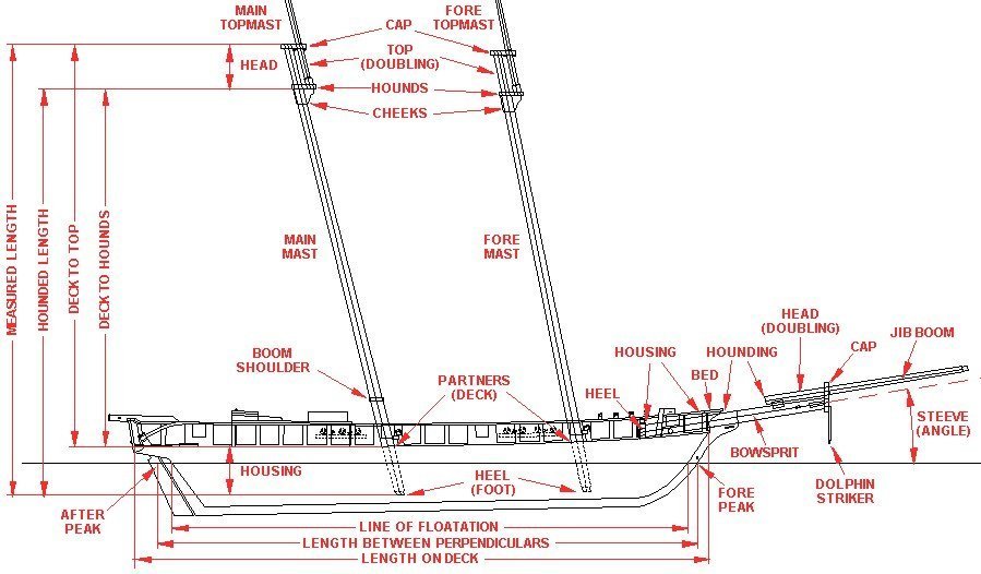
The meaning of "mast length" depends upon the author, and unfortunately most seem to think you can read their minds. Lees is no exception - at least I can find no place in the book where he actually states a definition of mast length. However, by comparing his tables to some of the drawings it appears he means the total length of the mast (measured length) from the heel (step, foot) or very bottom of the mast to the top of the top cap. Many authors use the "hounded length" for mast length, and one I came across used the length from the partners (deck) to the top of the top cap. When some say the "top" they are actually referring to the bottom of the doubling (the hounds) but most mean to the top of the top (doubling), or top of the top cap. The term "hounds" is another vague term. Some authors say the hounds start about 2/3 the distance from the deck to the cross trees, others say it includes the cheeks, and yet others say the hounds are the bottom of the doubling where the cross trees are supported. And "hounding" means the distance from something (deck, foot) up to the hounds, whatever they are. All the confusing, contradictory and conflicting definitions that people use - and assume everyone else knows exactly what they mean - gave me the greatest problems when trying to research how sailing ships were built. The meaning of many terms changes with time, so you have to know the period an author is talking about. You must never take any meaning for granted, and if authors do not say specifically what a term means, you really have no idea what they are talking about. Here is a drawing I made up to explain a lot of the terms used for ship's dimensions: Since you are new to all this, remember that rope dimensions are usually given as circumference unless otherwise stated to be the diameter. But masts and spar thickness is always given in diameters.
-
If you really want to get into the details get a copy of "The Young Sea Officer's Sheet Anchor," Darcy Lever (1808) and George Blunt (1858), Algrove Publishing Limited,Ottawa, Canada, 2000. The first part tells how to rig a ship and the second part tells how to sail a ship. It has an enormous amount of detail and information on ship handling.
-
If you decide to look forscale rope to match the ship type and size you might want to look at this thread I started on topsail schooner rigging. https://modelshipworld.com/topic/25679-topsail-schooner-sail-plans-and-rigging/?do=findComment&comment=750865 I have attached a spreadsheet for schooner mast and rigging sizes. Mast spar and rigging calculations.xlsx
-
Dave, I kept thinking Endeavor sounded familiar to me. When you mentioned the AOTS book I had one of those "duh!" moments. Sure enoough, I picked up a copy at a used book store years ago and it has been collecting dust on the shelf! The book shows studding sails outboard the course and topsail on the fore and main masts. There was a "driver" similar to a studding sail on the end of the gaff on the mizzen mast. The Anatomy Of The Ship book "Captain Cook's Endeavor," Karl Heinz Marquardt, Naval Institute Press, 1995. It is very well illustrated with a tremendous amount of detail. I recommend you get a copy if you can find it. If I can answer any questions from it for you just send me a personal message.
-
Dave, I am not familiar with the Endeavor so I suggest you find whatever you can that was published about the ship. But here is a guess as to why there were no studding sail booms on the topsail yards. First, the boom spread the foot or bottom of the sail. The top of the sail was laced to a (relatively) small studding sail yard which was hoisted to the end (yard arm) of the spar above. So if you have booms on the course (lowest) yards they are for studding sails that are raised outboard of the topsail. The booms stowed on the channels hooked into fittings on the hull or channel, and were used to spread the lower studding sails outboard of the course (lowest sail) and the studding sails were raised on studding sail yards that were hoisted to the yard arms on the course yards. This arrangement would provide studding sails for the lowest two spars on the mast. I would guess that there were no studding sails for the topgallant or royal, if the ship had these sails. Therefore there would be no studding sail booms on the topsail or topgallant yards. Mark's comment about changing tack must be spot on. There were enough other lines and sails to be messed with. Raising and lowering studding sails would have added a lot of work. One thing to remember about sailing ships is that nothing happened very fast. Eight to ten knots was a good speed for most ships (but clippers often moved twice as fast). Changing tack took quite a bit of time, especially on merchantmen with small crews. So the studding sails would be used only when the wind was right and the ship would be on the same tack for quite a while. Period paintings often show studding sails rigged only on one side. For what it is worth, I knew little about sailing ships when I started modelling, and I still know a lot less than some of the "old salts" on this forum. But I am learning, and that is a big part of the enjoyment of model making for me!
-
sail plan for Ballahoo (Fish class) topsail schooner
Dr PR replied to georgeband's topic in Masting, rigging and sails
Wefalck, Good point about the hull shape determining the type of ship and not the rigging, at least before the early 1800s. Also a good question about the flying jib. There is some ambiguity about the term "flying jib." Lees (page 126) says it was introduced after the "flying jibboom" was introduced (but doesn't say when). He states further that it was secured to the "flying jibstay" with hanks. So in this case "flying" does not mean hoisted without attachment to a stay. But he is talking about English square rigged warships, and there is little of anything in his book about schooners or other small craft. Marquardt (page 181) says the jib and flying jib can be rigged to a stay or set flying. He says the jib boom was introduced about 1695 and became official in the Royal Navy in 1705. He doesn't mention a flying jib boom. So perhaps a "flying jib" precedes the flying jibboom. Mondfeld (page 226) says the flying jib boom was introduced in the late 18th century. So that puts the advent of the flying jib as likely sometime in the 1700s. I looked through Chapelle's "The Baltimore Clipper" for examples of a jib or flying jib set high. On page between 70-71 there is an image of a watercolor of the hermaphrodite brig Diomede ,built in 1809, with what appears to be two sails on a stay from the end of the jib boom to below the topgallant. The lower sail would be a second jib (there is also a jib and a fore staysail) and the upper sail appears to be a flying jib. And that is the only illustration of a high flying jib in the book. The vessel is also flying top sail studding sails, a fore course, and a main gaff topsail - it has just about as much sail as it can get aloft. Marquardt (page 127) shows the sail plan of the American centerboard schooner Vigilant (1843) with a fore staysail, a jib on a jibstay rigged to the end of the jib boom, and a third jib rigged to another stay running from the end of the jib boom to the top of the fore topmast. This third "flying jib" is hoisted to the top of the stay at the mast top, and the foot is more than half way up the foremast. This is a clear example of the high hoisted jib. There are a number of oddities about this sail plan, including a fore course with a bonnet but no fore topsail, and a spar gaff topsail on the mainmast with the spar horizontal (European style). Leather's "The Gaff Rig Handbook" shows many examples of high flying jibs. On page 48 he describes a "jib topsail" that is similar to the high flying jibs in the illustrations. The tack is rigged to the bowsprit or jib boom with a pendant. He shows drawings with this sail on pages 92 (a government cutter ca. 1840), 100 (a fruit carrying cutter ca. 1853), 112 (the cutter Santanita ca 1893)113 (the Valkyrie III ca 1895), 115 (cutter Lily Maid ca 1904), 153 (schooner Andrew M. Lawrence ca 1885), 176 (ketch Cariad 1896),188 (schooner John Feeney 1885), and several other vessels of the 20th century. Several of these were racing vessels with a lot of sail. So there are many examples of vessels with jibs/flying jibs hoisted high on ships of the mid to late 1800s and one from the early 1800s. Personally, I think that any way you can imagine a ship could possibly be rigged was probably tried by someone at some time. If I had to guess I'd bet that the head sails would be adjusted to take best advantage of the existing wind. And in many cases there is a stronger breeze high off the water than on the surface. That's what topsails, top gallants and royals were used for, and on schooners you could haul up main top stay sails, main gaff topsails, studding sails for the fore topsails and a topgallant. Since the leech of jibs were often much shorter than the stays they were hoisted on, if necessary the halliards could be hauled in while the tacks (see below) and downhauls were let out, raising the sail high on the stay. And that give me an idea as to the nature of "flying jibs." The tacks of jibs were usually attached to a traveller or directly to the jib boom. Perhaps a "flying" jib's tack was just attached to a tack line that ran through a sheave and back to the foc'sle. That would allow the height of the sail to be adjusted with the halliard and tack. This is apparently what Marquardt is showing on page 127 on the Vigilant. But that is the only place I have seen anything like it. **** Marquardt (page 185) does show the water sail or lower studding sail hanging horizontally below the main boom. It is rigged to a spar at the aft end, just as ordinary studding sails are rigged to a yard that is hoisted by the halliard. So it is easy to see how the water sail might also be called a sudding sail - as the ringtail is also similar to a "studding sail." Like George I enjoy the research as much or more than building the model. That's why my CAD model of the USS Oklahoma City CLG-5 took 14 years to complete (well, almost complete). I had to research everything along the way, and even post a web page with the results of the research. I guess I am in it more for the chase than for the kill.- 22 replies
-
- 2
-
-
- caldercraft
- jotika
- (and 4 more)
-
sail plan for Ballahoo (Fish class) topsail schooner
Dr PR replied to georgeband's topic in Masting, rigging and sails
George, I am hardly an authority for schooner sail plans, but just a student! With respect to the fore stay, it seems to me that the position of the fore mast determines whether the stay attaches at the stem post or at the end of the bowsprit. Some schooners had the fore mast very close behind the stem. The schooner in Petersson's "Rigging Period Fore-and-Aft Craft" (based upon the Experiment) has the fore mast forward almost at the base of the bowsprit, and the fore stay and preventer running through the bees behind the bowsprit cap. The Prince de Neufchatel had the fore mast farther aft and the fore stays attached to the stem posts. Looking through Chapelle's The Baltimore Clipper it seems the stay attached to the bowsprit behind the cap (bees) is more common, but there were a couple of examples where the fore stay was attached to the bowsprit about half way between the cap and the stem! I guess the question I would ask is whether or not the fore stay was positioned far enough ahead of the mast to allow the sail to have a useful area? If the mast was positioned near the stem, and the forestay attached to the stem, a fore staysail wouldn't make much sense, so the first headsail would be the jib, and the jib stay likely would be attached to the bowsprit at the bees. I would certainly base my work on the plans at Greenwich. Marquardt's book has the greatest detail for schooners of any book I have found, but much of it is based upon his experience with the Australian schooner Enterprize. Some of his terminology leaves me scratching my head trying to figure out what he is talking about. Wefalck on the Forum has said Marquardt was from Germany, and was more familiar with northern European vessels and their terminology before migrating to Australia.- 22 replies
-
- 1
-
-
- caldercraft
- jotika
- (and 4 more)
-
My junior high school shop teacher had a jar full of formaldehyde with one of his fingers in it. He brought it out and passed it around on the first day of each semester. When I was a kid I knew a carpenter who was missing one finger - power saw accident. One day he came home missing another. Get careless and you pay the price. Having just passed Christmas brings to mind a personal Christmas story. I had been working on some hobby project and had a few hours Christmas morning (before I was married) before I had to go somewhere. So I was working with an X-Acto knife cutting something. I had very good vision so I didn't need glasses, and safety glasses just blurred things a bit. The extreme tip of a NO. 11 blade broke off and stuck in the white of my eye. I couldn't close my eye because the metal cut into the inside of my eye lid. Talk about pain!! I called a fellow I worked with and he came over and drove me to the emergency room. They removed the splinter and gave me some eye drops to relieve the pain. It was a not-so-merry Christmas! So I learned my lesson about wearing safety glasses when using tools that might break or chip and produce splinters.
-
Topsail schooner sail plans and rigging
Dr PR replied to Dr PR's topic in Masting, rigging and sails
Paul, A sling is tied around the treble block and around the lower mast at the top. This just supports the block. The halliard goes through the sheaves in the block. I think that's what the three short lines below the block are supposed to represent. There could be a double block fastened to a ring bolt on the jaws of the gaff. The halliard would go up from the left and through the treble block, to the double block, up through the treble block, back down through the double block, and up through the treble block again and then down to the right. You need to find a good resolution photo of the main mast top and main gaff jaws. There is a fellow on the Forum who works on the Pride of Baltimore II and has posted some photos. Look through my Topsail Schooner Rigging thread (I think that is where I saw his posts). He could clear this up for us.- 104 replies
-
- 4
-
-
- schooner rigging
- Topsail schooner
- (and 1 more)
-
Topsail schooner sail plans and rigging
Dr PR replied to Dr PR's topic in Masting, rigging and sails
Paul, The configuration of both the peak and throat halliards is interesting because it reflects the limitations of tackle and the requirements for handling the gaff sails. First, the throat halliard. This line raises and lowers the end of the gaff close to the mast. On the left side is a line that is belayed to a cleat or pin on the bulwark, runs through a lead block attached to a ring bolt in the deck and up to a treble block (throat block) attached to the mast top and then down to the right where this line is fastened around a double block. The upper throat treble block is part of another tackle with a double block attached to a ring bolt in the jaws of the gaff. The left hand line passes around the treble block and down to the double block, back through the treble block and double block, and back up through the treble block and down to the right to the double block. The double block is part of a tackle with the lower double block on the right side attached to an eyebolt in the rail. The right hand tackle line is attached to the upper double block, runs through the lower double block, back up and around the upper double block, down to the lower double block again, and then back up and around the upper double block. The free end of the right line is belayed (fastened) to cleats or belaying pins on or near the base of the mast or to cleats/pins on the bulwark. The tackle on the right serves to raise the heavy gaff and attached sail. The tackle provides significant mechanical advantage for hoisting then load. But multi-block tackles are relatively slow. You have to pull three feet/meters on the free end to raise the single block one foot/meter. Sometimes it is necessary to lower the gaff and sail quickly. The left side line solves this problem - just loosen the end that is belayed to the bulwark and let it run quickly to allow the gaff to fall. I think this rig is unnecessarily complex, and I question whether any ship was actually rigged this way (of course if it is possible someone probably tried it at one time of another). Normally the throat halliard is rigged in one of several ways. The first was used on vessels with heavy gaffs and sails, and consists of a line attached to a ring bolt on the gaff jaws, passing through a single (throat) block attached to the top, with the line running down and fastened to a double block that is part of a luff tackle. The single block of the tackle is attached to a ring bolt on deck. The running part of the luff tackle line is attached to the single block, passes through the upper double block, back thorough the single block, over the double block again and the free end is belayed to a pin or cleat on the bulwark. The second was used on smaller ships with lighter gaffs and sails, and is a bit simpler. A luff tackle single block is attached to a ring bolt on the gaff jaws, and the double block is fastened to the mast head. The fixed end of the line is fastened to the lower single block, runs through the upper, lower, and upper blocks and down to the deck. This end could be belayed near the bottom of the mast, but this would provide a relatively slow way to lower the gaff. Or the end could be attached to a single (whip) block. The Whip line was attached to a ring bolt on deck at one end, ran through the whip block, and back down to a belaying point on deck. To lower the gaff quickly the whip line was released. A slight variation of the second method used a double block at the gaff jaws and the double block attached to the mast top. This gave a bit more mechanical advantage for raising the gaff. The method shown in your drawing appears to be a combination of the first two methods. With the mechanical advantage of the treble throat block I do not see why the right hand tackle was necessary. Of course the crew of the Pride II was not made up of burly hardened sailors so maybe they needed that extra mechanical advantage? I have the book "Pride of Baltimore" (International Marine, Camden, Maine, 1994) by Thomas Gillmer. On page 163 is a sketch of the sail plan of the ship, and it shows a two block throat tackle similar to the second method (a luff tackle with one end of the line attached to the lower block. How the free end of the tackle was belayed is not shown. Like many authors, after many pages of detailed description of the hull he says "Oh, yeah, it also had sails." **** The peak halliard shown in your drawings is rigged similar to the description above for the throat halliard, with right and left sides reversed. Instead of the treble throat block the peak halliard was rigged with three "peak blocks shackled to eyebolts." It shows the end of the left side going to one of the blocks (lower) and the end of the right side going to another (upper) block. Again, this seems a bit strange. Without the drawing of the gaffs I can't say how the blocks were arranged. Karl Heinz Marqiardt's "The Global Schooner (Naval Institute Press, Annapolis, 2003), James Lees "Masting and Rigging English Ships of War" (Naval Institute Press, Annapolis, 1990) and John Leather's "The Gaff Rig Handbook" (Wooden Boat Books, Brooklyn, Maine, 2001) show at least a dozen ways to rig the peak halliard, and none resemble what is shown in your drawing. Gillmer's "Pride of Baltimore" drawing shows something similar but distinctly different for both gaffs. The fore gaff peak halliard fixed end if secured near the end of the gaff. It leads through a single block attached near the mast cap, down through another single block attached near the midpoint of the gaff, back up through a third single block attached to the lower mast between the trestle trees and the cap, and then down to deck. How the free end is belayed is not shown. The main gaff peak halliard is fastened to a single block that is attached to the mast cap. The line runs down to another single block attached near the end of the gaff and back up through the first single block. From there is runs down to another single block attached near the middle of the gaff and back up to a fourth single block attached to the lower mast close below the mast cap. Then it leads down to the deck, and the means of belaying it is not shown. Both of these configurations are fairly common. In neither case does the peak halliard have two running ends. It would be possible to lead down from the top to a luff tackle on deck, as shown in your drawing.- 104 replies
-
- 3
-
-
- schooner rigging
- Topsail schooner
- (and 1 more)