iMustBeCrazy
-
Posts
967 -
Joined
-
Last visited
Content Type
Profiles
Forums
Gallery
Events
Everything posted by iMustBeCrazy
-
 The main problem is that you're trying to put a square plank in a curved hole. On the plank, the top edge (X) is the same length as the lower edge (Y). On the hull, the path taken by the top edge (X) is longer that that taken by the lower edge (D). Something has to give so the lower edge of the plank bulges out from the hull trying to make a new path that is the length of the plank lower edge. If you force the plank flat against the frames the plank will bulge out between frames so as to stay the same length. This can be prevented by either cutting your planks to shape or by edge bending your pre-cut planks.
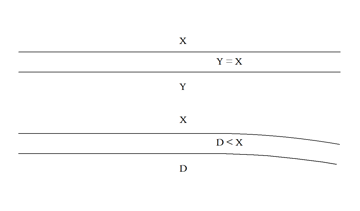
-
I found this: And on a replica:
-
Been there, done that I see lots of spare wood there. Just cut carefully. Edit: I should expand on that. Get yourself a stainless steel ruler with a straight edge (officeworks has some cheepies, hold two together and check for no gaps, flip one end for end and check again, flip it sideways and repeat until you find a straight one, they're pretty good so the first one will probably work) glue some 400 grit wet and dry sandpaper to one side to prevent slipping. Cut with many very light cuts.
-
I and others differentiate between frames, cut timbers forming the shape of the boat, and ribs, bent strips holding the planks together. But not everyone agrees. Me too.
-
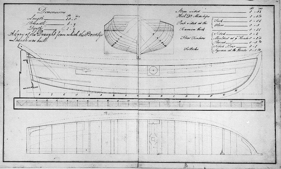
Quite a lot would go into a kit design: Which vessel? What information is available? What cost? What skill level? How repeatable? (in manufacture) What compromises re cost skill level etc. This Bounty Launch kit is probably based only on this drawing: Which appeared in Bligh's books. The kit hull shape is quite close but the construction (which is not shown) is very different. Also there are errors made by the person who etched the plate for the printers. But the bottom line is that it makes a nice model and is a better representation than some of the other kits.
-
Greg, I hate to ask but how are you going to cover the pontoon?
- 288 replies
-
- 3
-

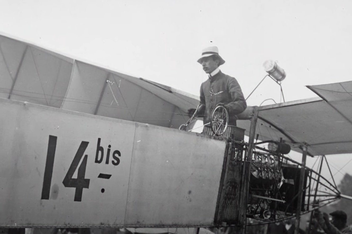
-
- Santos Dumont No. 18
- hydroplane
- (and 1 more)
-
Technically I suppose this is an inwale, an inner gunwale. I have seen no contemporary plans showing inwales in a launch. An inwale may be used alone or paired with an outwale (outer wale or gunwale). Weirdly, if a gunwale is notched to go over the ribs it also becomes an inwale. So, Nick is correct, it's just a design feature of this kit as is the use of ribs on a launch.
-
I used Topaz Photo AI to upscale them, it's not perfect so you have to be careful about what you believe. I don't blame you, there are so many colours that fit. Given it's a light blue grey one of these might fit: And converted to black and white (well greyscale): I'm leaning towards the middle two. Or perhaps a little more black and a little less blue.


- 288 replies
-
- 5
-
-

-
- Santos Dumont No. 18
- hydroplane
- (and 1 more)
-
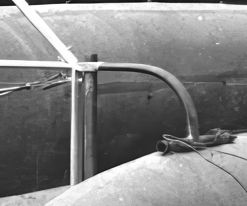
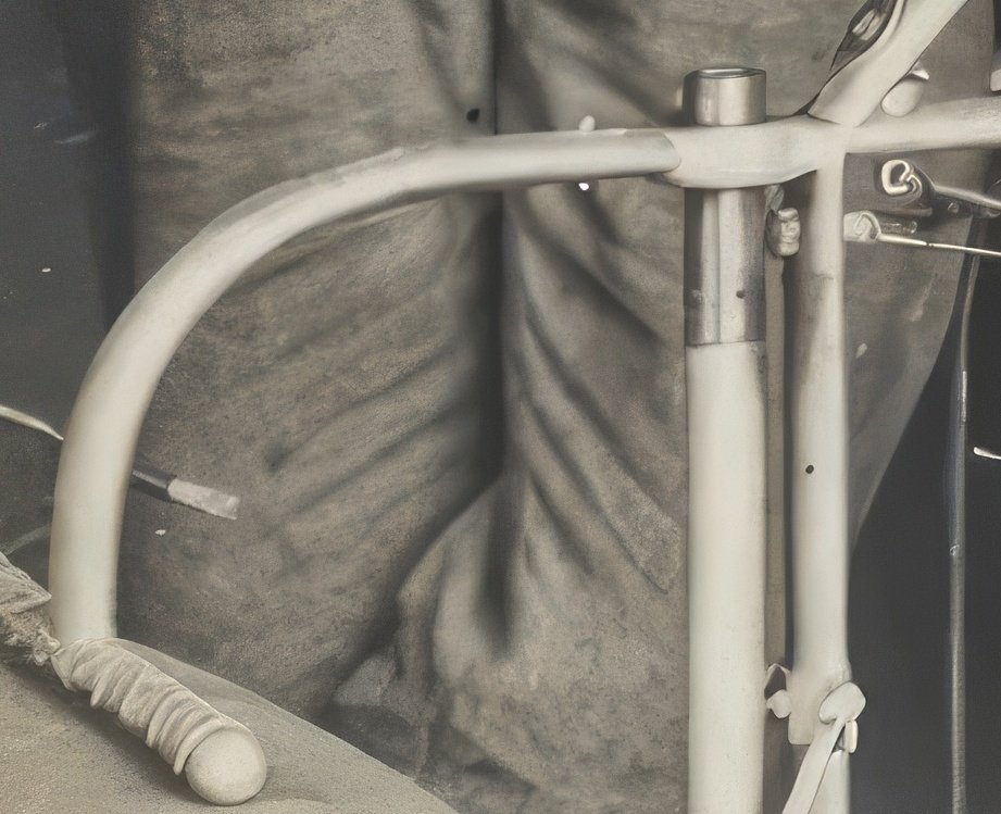
I've had a look and a long think and my 2c goes to painted steel. The following two pics tell the story, the suspension upright and the bent support are bare metal in the first pic, both are the same colour and not aluminium. In the second pic the suspension upright looks like bare steel at the top and except for that bit both are now coated in a pale colour (it could be any pale colour, pale grey, pale blue, pale yellow, pale red, pale green, any pale colour) but not white. The other struts with the flattened ends, well aluminium doesn't like that unless it's soft and then it bends really easily. It could be done but I suspect not. Steel bicycle tubing seems the most likely.
- 288 replies
-
- 7
-
-
-
- Santos Dumont No. 18
- hydroplane
- (and 1 more)
-
Congrats Nick, she's looking good. The issues you had are all inherent in this kit and you handled them nicely.
-
Peter, I suggest you watch Leo's (Sampson Boat Co) videos on YouTube. Particularly episodes: 24 and 25 Lofting, 27, 28 and 29 Frames, 78 Lining out, 85 and 86 Planking, 91 and 92 More planking. This will fill in some of your blanks and entertain you as well.
- 44 replies
-
- 1
-
-
- bounty jolly boat
- Artesania Latina
- (and 1 more)
-
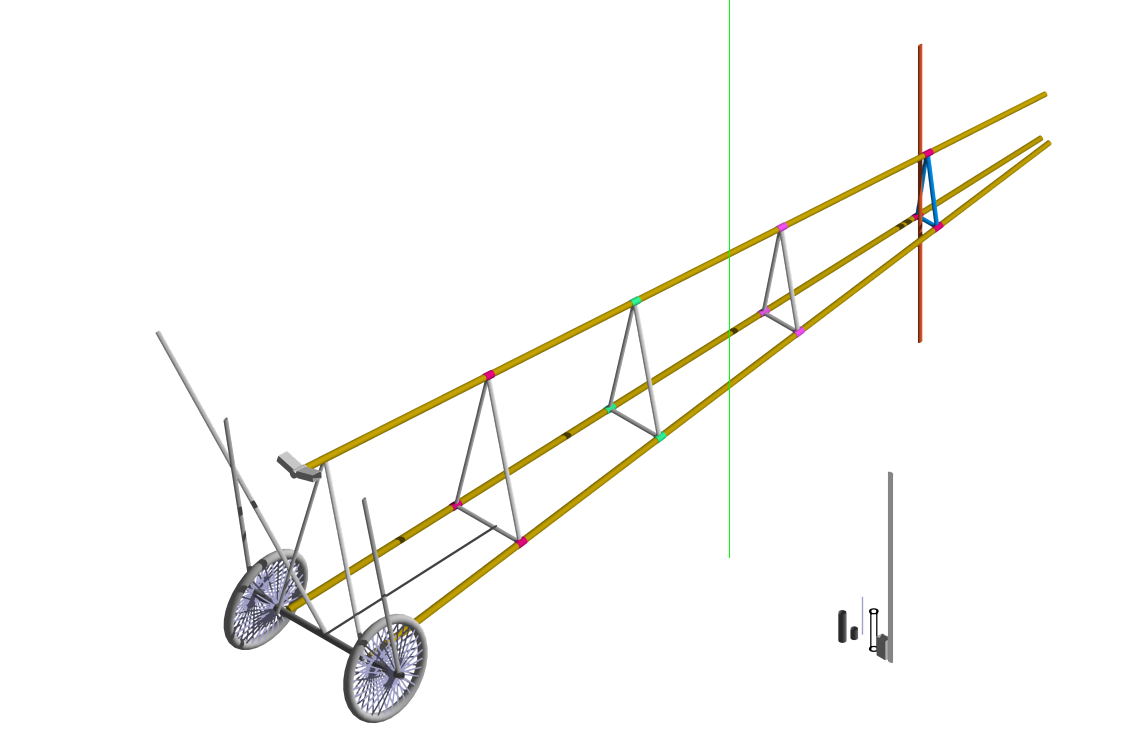
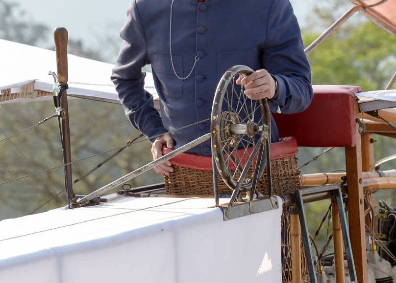
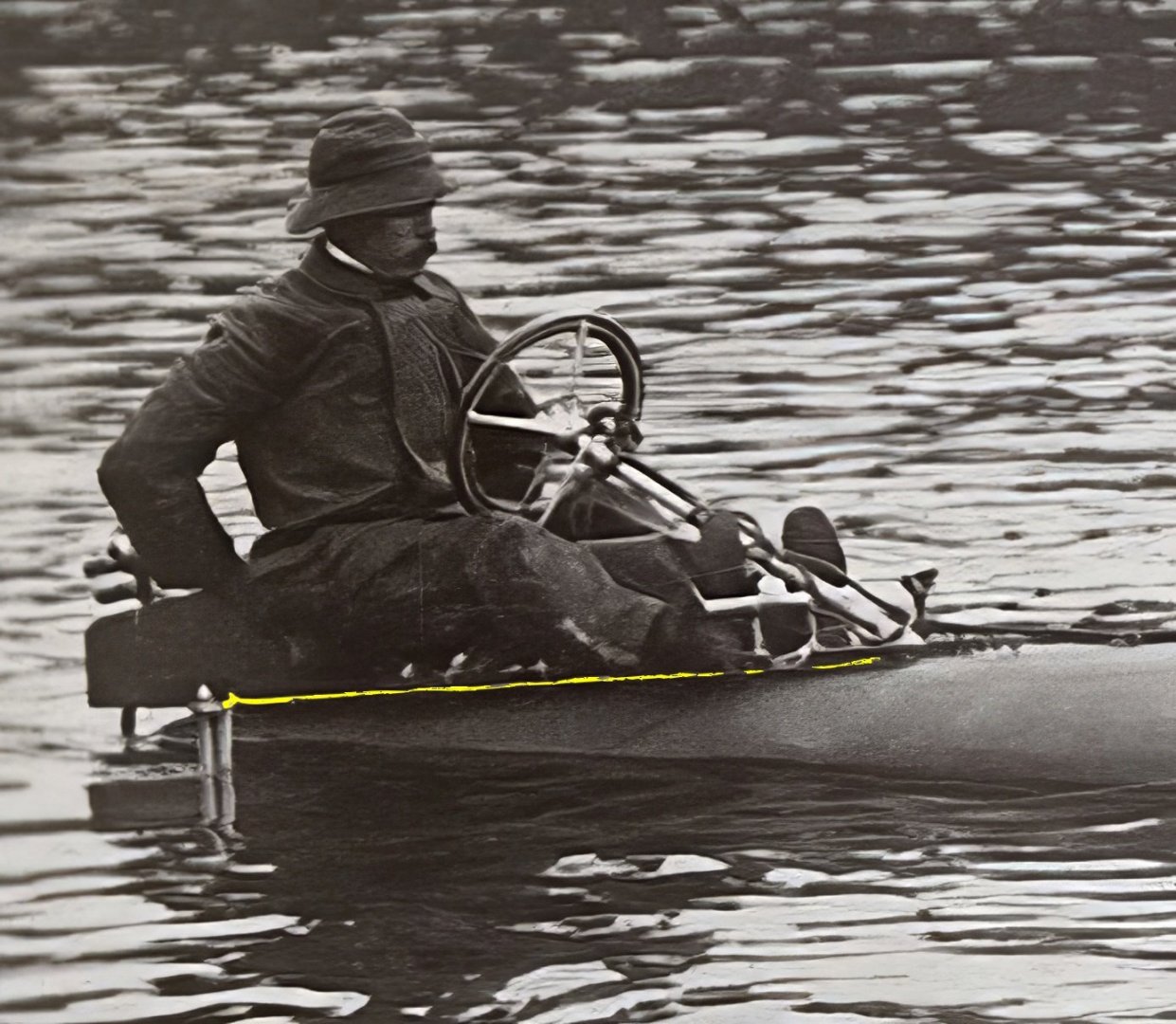
Looking at it this way I think the rear foil mounts to the same ring as the foot brace. The support for the steering column mounts to the next ring, the board extends from the end of the steering column to just aft of the seat, the foil is also wider than the earlier one. Greg, note the flag in the pic you posted, probably for signalling the tow boat. Still guessing though.
- 288 replies
-
- 6
-
-
- Santos Dumont No. 18
- hydroplane
- (and 1 more)
-
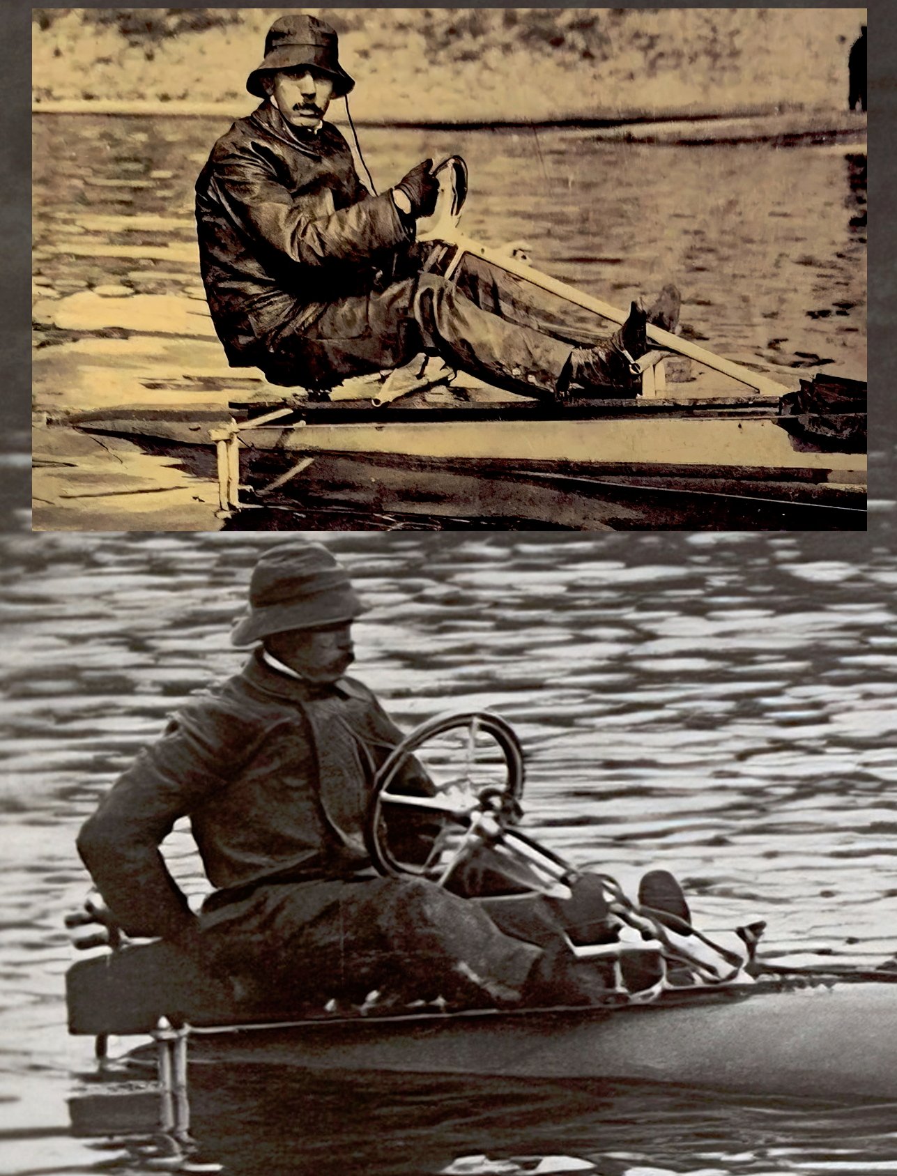
Thinking about it, the top one may have been a prototype and may even have been towed.
- 288 replies
-
- 3
-
-
- Santos Dumont No. 18
- hydroplane
- (and 1 more)
-
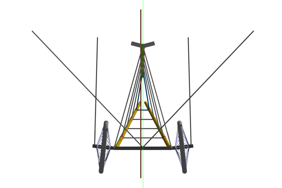
It looks like he made modifications in that area: It looks like there were two different variants or something. Anyway, in the top pic the hydrofoil mounts under his backside and in the bottom pic it mounts approximately under his knees. (I think).

- 288 replies
-
- 6
-
-
- Santos Dumont No. 18
- hydroplane
- (and 1 more)
-
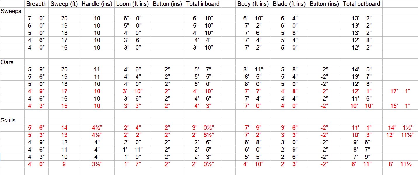
Steels tables break down in to SWEEPS, OARS and SCULLS: As you can see from the inboard length compared to the breadth he hasn't included oars for double banked boats. The sculls would fit but they are for one rower with two oars. Double banked oars should (I think) have 10" handles, a total inboard length of under half the breadth and be shorter than single banked oars. NOTE: The button is 2" down the body so has been added to inboard and subtracted from outboard. The rows in red don't add up to the sweep.
-
Certainly, but the boat is fitted with as a hybrid rowing system. I suspect it was something like preventing resentment of the rest of the crew if the bowman was carried around like an Admiral. ¯\_(ツ)_/¯ ------- Anyway, I thought trying to nail down terminology might be worthwhile. I think this is how it goes: Starting with OAR, basically every paddle worked against a fulcrum (THOLE) is an oar. Oars are broken down into two types, SCULLS and OARS. (there is also SWEEPS which are 'larger OARS' used on ships or boats). SCULLS are operated by one man SCULLING with one oar over the transom or one or more men operating two oars each on the one thwart (also called SCULLING). OARS are operated over the sides of the boat by one or more men per OAR. They can be single (one oar per thwart) or double banked (two oars per thwart), single banked would tend to use SWEEPS. Operating a boat with one or more men per OAR, with the oars over the sides, is known as ROWING. To add to the confusion, an OAR operated over the transom could be called a SCULL if used for propulsion or a SWEEP if used for steering. And SCULLS and OARS were also the two types of "water taxis" used on the Thames. Maybe.
-
I came across this pic of Police on the Thames which opens a new can of worms:
-
This is what I can come up with for pinnaces:
-
The problem is a lack of standards. There were no drafting text books so it was a case of doing as you were taught. Some drawings such as the one above may, for example, depict a half hull model while others the whole boat. When depicting the whole boat, sometimes objects the far side of the centreline are drawn dashed, sometimes solid. Sometimes extra details are depicted on the half breadth, sometimes not. Ultimately these drawings are not the engineering drawings of today, they are general guides backed up by scantling details and contracts which we rarely see. Or the might be right, but I don't think so.
-
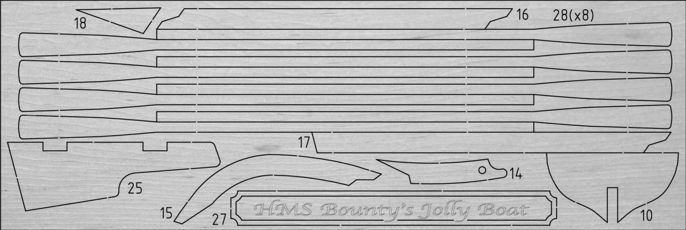
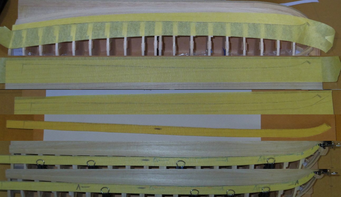
Alfredo, it has little to do with the number of planks, it is about the shape. (although narrower planks are easier to bend sideways). The kit planks are rectangular, mine are shaped (a bit like a ski, see the photo) to fit against the previous plank. This process is called 'spiling'. Spiling can be simulated by 'edge bending', forcing a plank to bend sideways with the use of heat, but wood doesn't like doing that. I find cutting the plank out of a wider piece of wood easier.
- 19 replies
-
- 2
-
-
- Bounty Boat
- OcCre
- (and 2 more)
-
G'day Alfredo, I think that, given you were trying to do 'correct' planking with the wood supplied, you've done quite a good job. First, a reminder that your planking is quite thin (I think 0.5mm) so it can't stand much sanding, go easy. For any very low areas try gluing another layer of planking over the top of the low area (matching colour and grain as best you can) then sanding it down to blend it in. This is so you don't sand too much off adjacent planks trying to match the low area. A little glue applied with a pin in the holes and gaps then a light sanding to get sawdust into them will help, do one at a time and repeat if you have to. Only after you are happy with your fixes, lightly sand the whole hull.
- 19 replies
-
- 1
-
-
- Bounty Boat
- OcCre
- (and 2 more)
-
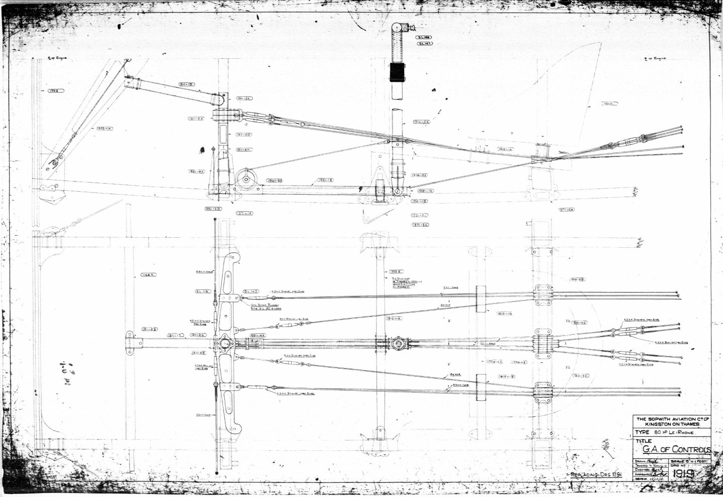
Probably a bit late but this is the general arrangement drawing of the controls of a Pup which would be very similar to that of a Camel.
-
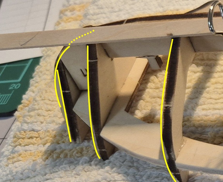
G'day Peter, I found this description on another site, The goal of hull fairing is to bevel the edges of the bulkheads so that the hull planks lay flat. If we didn’t do this, the planks would only hit the corners of the bulkheads. The problem is it only tells a part of the story. The aim of fairing is to have a finished hull with nice flowing lines, without lumps bumps hollows or kinks. Simply bevelling the frames without considering this only allows a greater gluing area, which although important, is only part of the story as I said. Your plank (or batten) should sit naturally against the intermediate frames if held down a few frames apart. Looking at your second pic you would probably have needed to sand the areas indicated below. But only enough to allow the plank to fit.
- 44 replies
-
- 2
-
-
- bounty jolly boat
- Artesania Latina
- (and 1 more)