Mahuna
-
Posts
1,504 -
Joined
-
Last visited
Content Type
Profiles
Forums
Gallery
Events
Everything posted by Mahuna
-
 Hi Patrick - I'm glad you're back! It looks like you've made some real progress. The tenders really are tiny, but they look good already.
 -
Beautiful, Ed. How did you transfer the shape of the cleats to the brass plate? Did you paste the drawing to the plate, or simply scribe the shape of the cleats onto the plate, or some other way?
- 3,618 replies
-
- 2
-

-
- young america
- clipper
- (and 1 more)
-
Thanks Carl. We're looking forward to the 30+ degree difference! Thanks Druxey. and Ed I'm very comfortable with the rotary tool, having used it for years in bird carving. Of course, I wouldn't try this with a Dremel - my rotary tool is a higher quality (used by jewelers) and is controlled by a foot pedal and is very smooth running. Hi Ron. I'm glad you mentioned this. I was under the impression that there should be a slight downward bend to the bowsprit, and I actually made one but it just didn't look right. I spent a lot of time with the plans and photos and finally realized it should be straight. I have some photos of Kathryn taken during the HAER survey and they show the straight bowsprit. If the bowsprit had been changed it would have been during the 1950's rebuild. Thanks Ed. All of the metalwork on Kathryn will be quite a challenge and I'm looking forward to it. I'm trying to get all of the wood construction completed before I start on it. I'm hoping to see the Kathryn on a trip east in October so I can get a lot more photos. I'll need to be careful on replicating what I see since some of the components, especially related to the shrouds, have changed since the HAER survey. Luckily I have a friend who knows the former setup really well and can help me decide what each component should be.
-
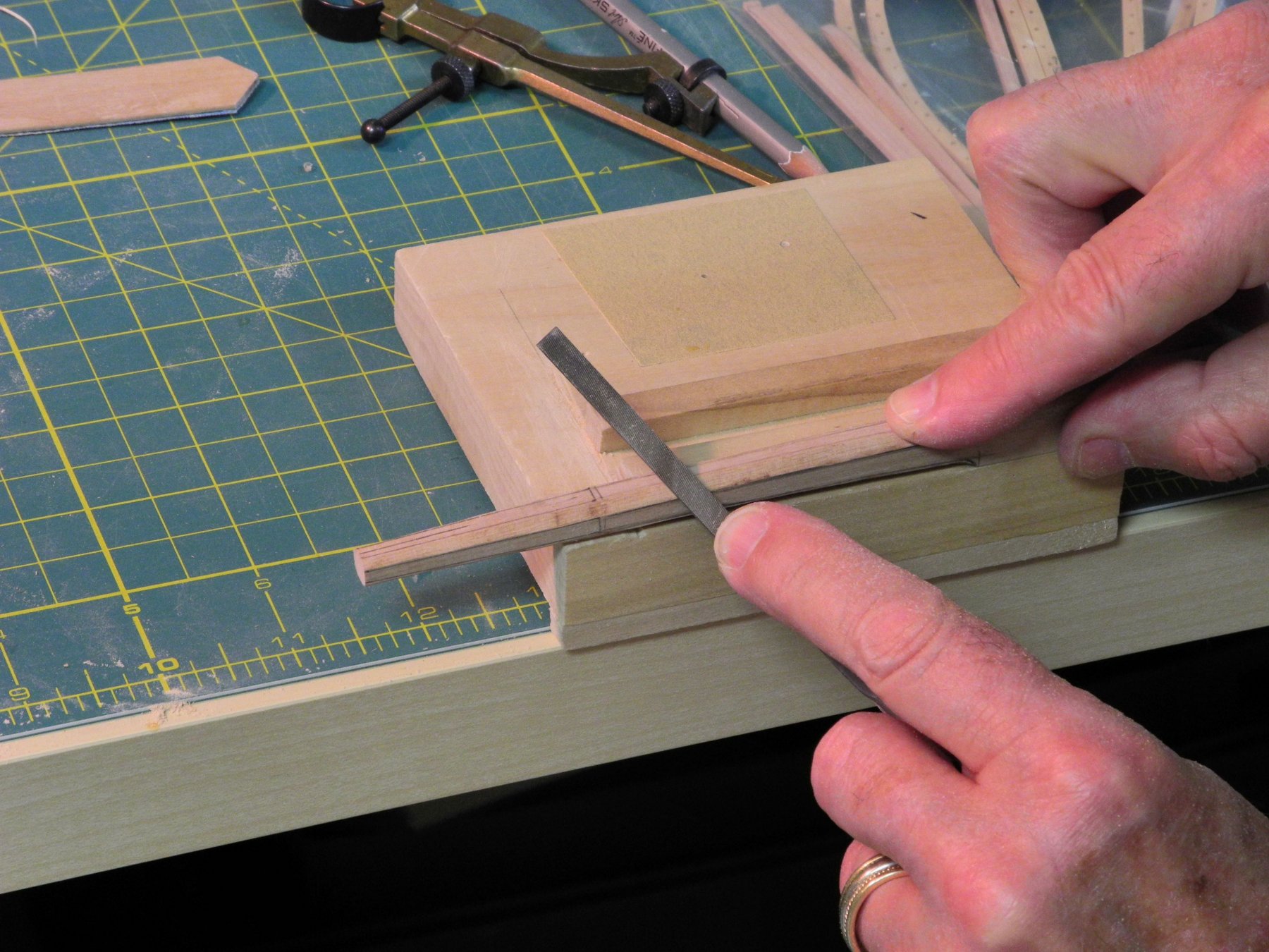
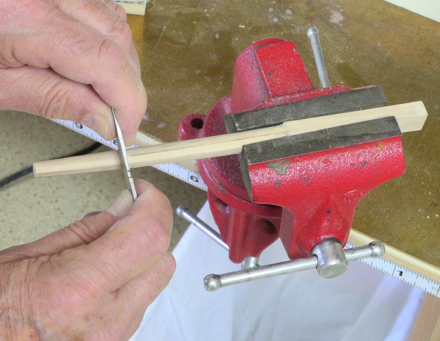
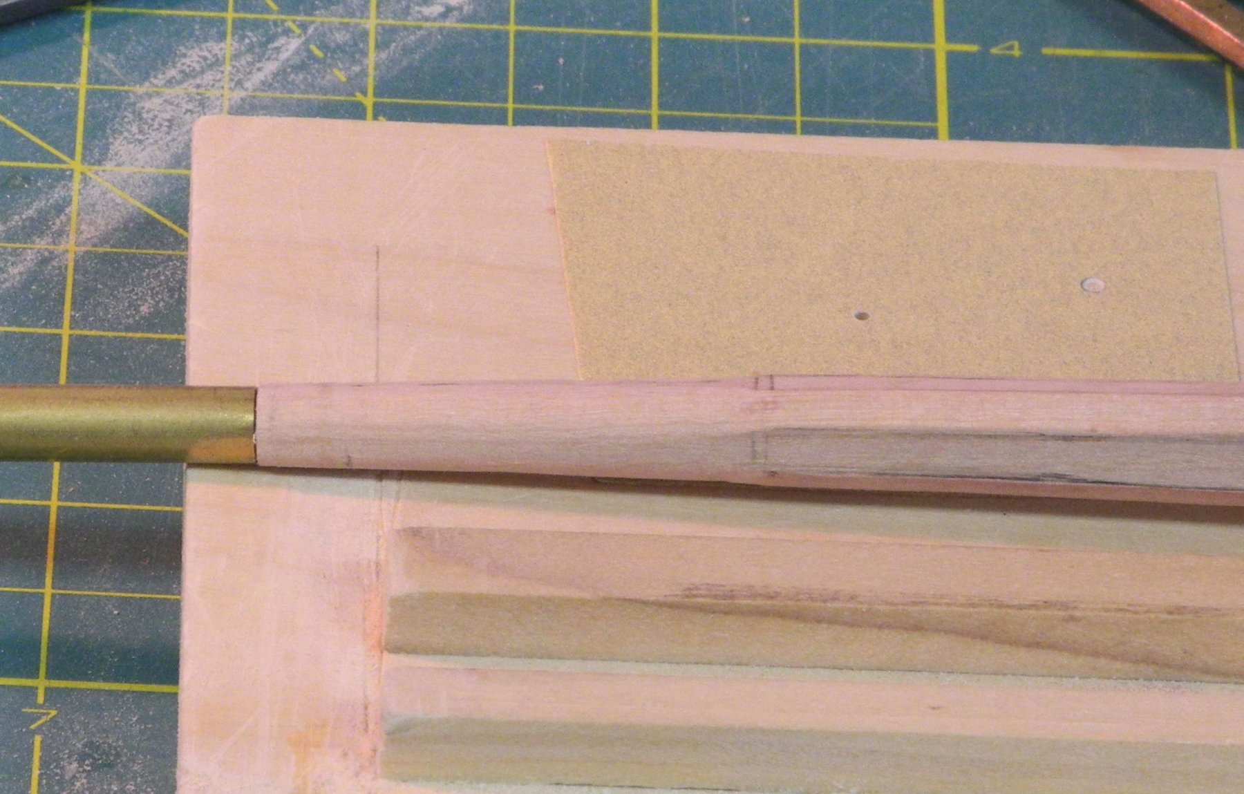
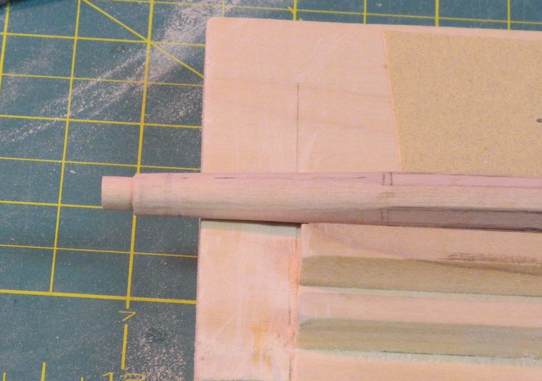
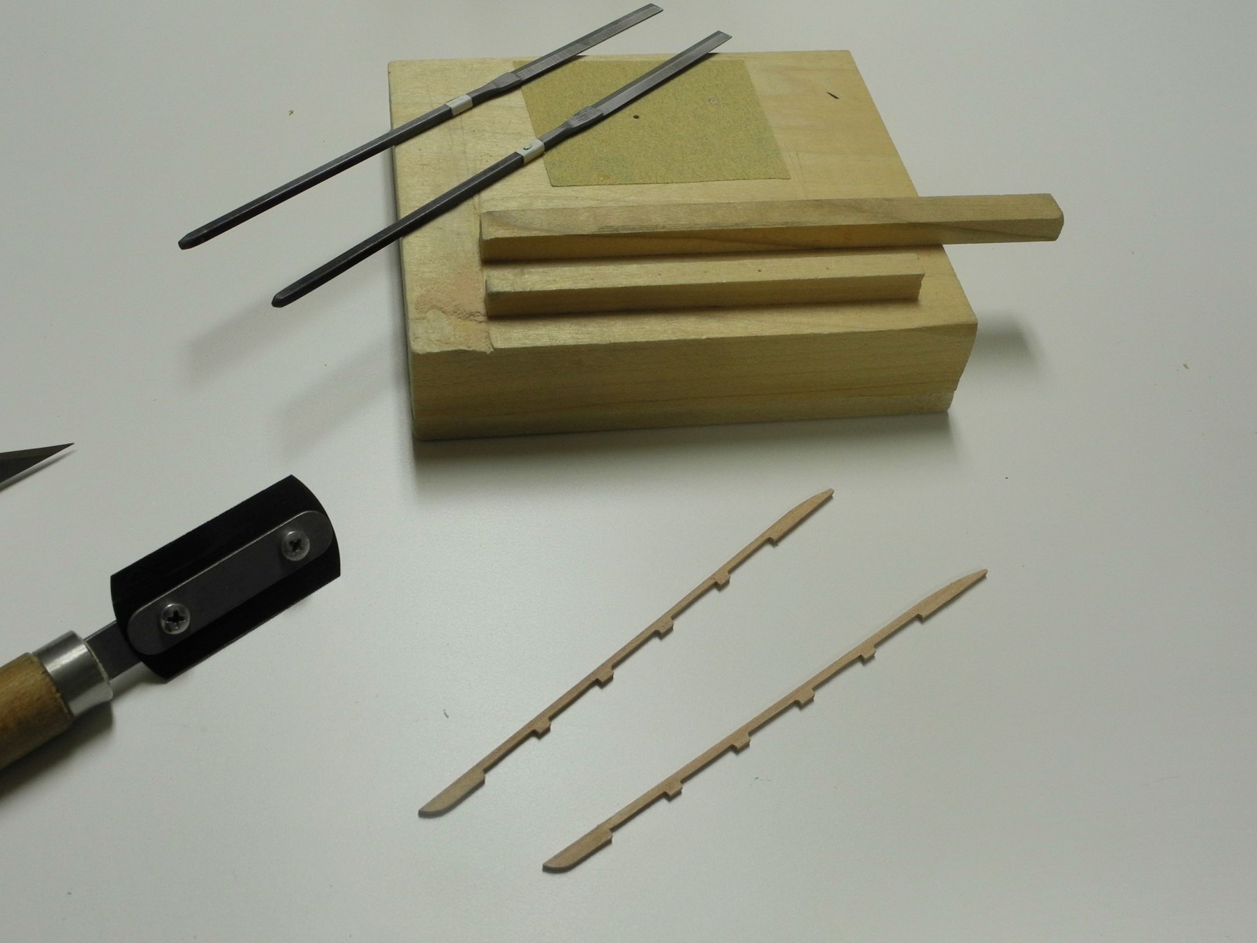
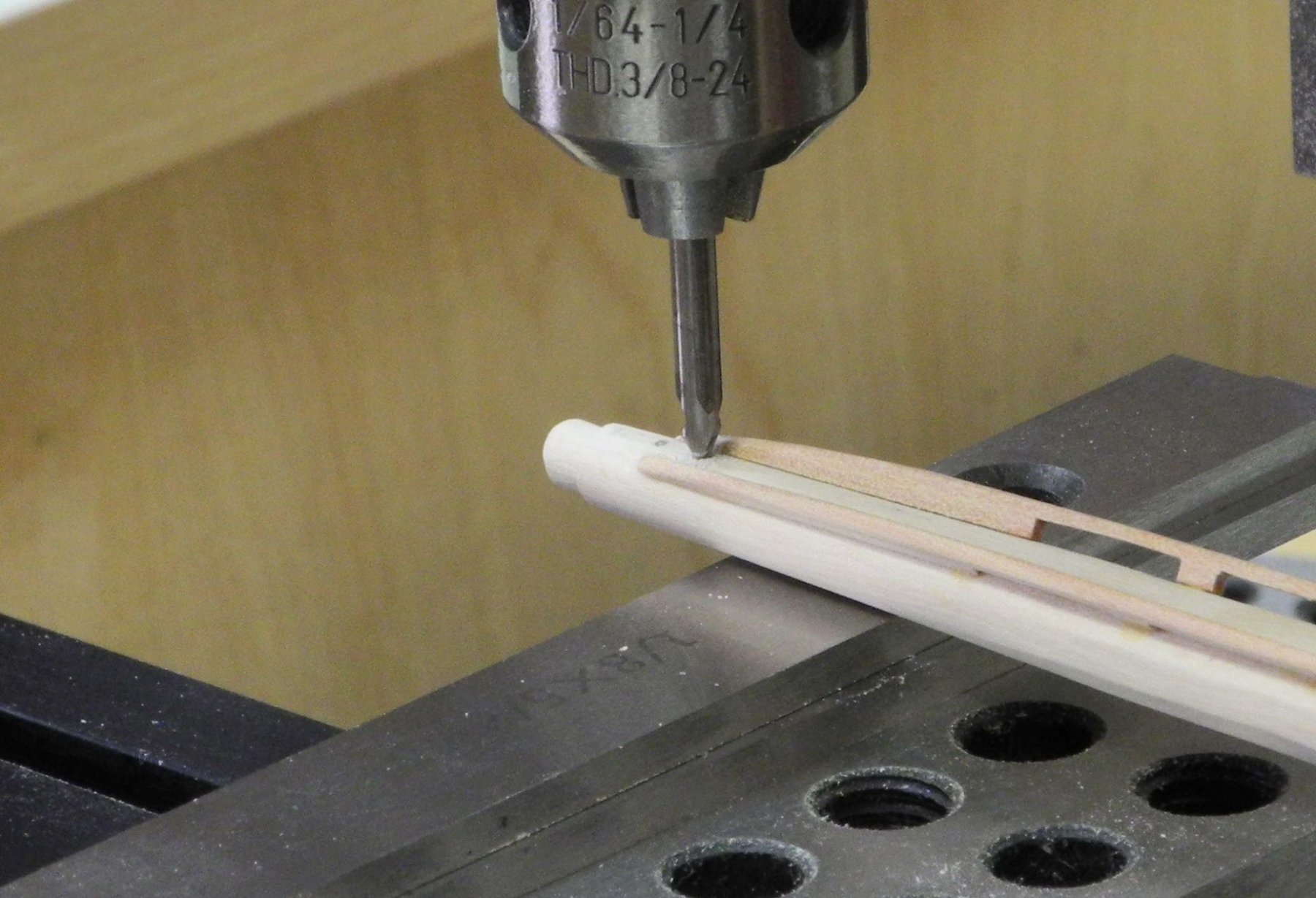
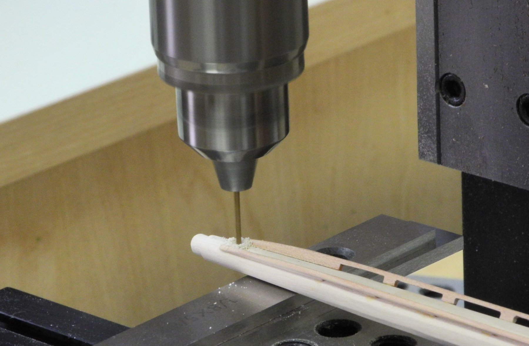
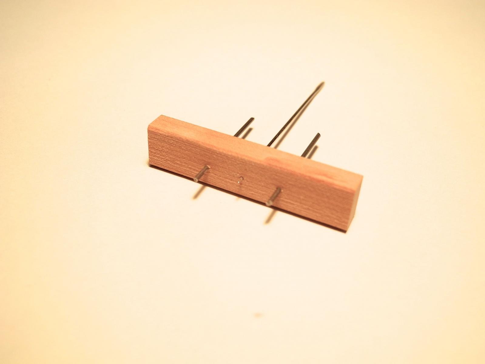
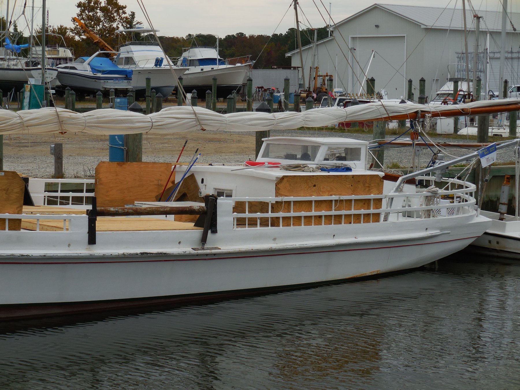
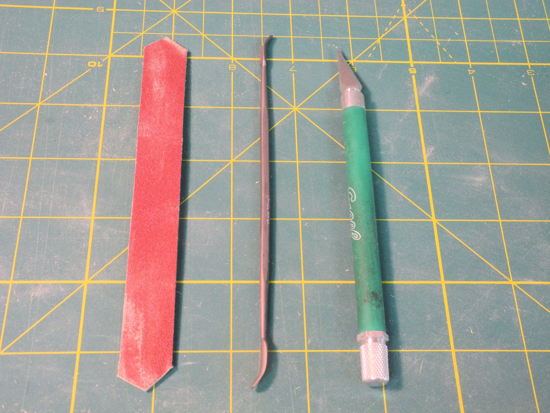
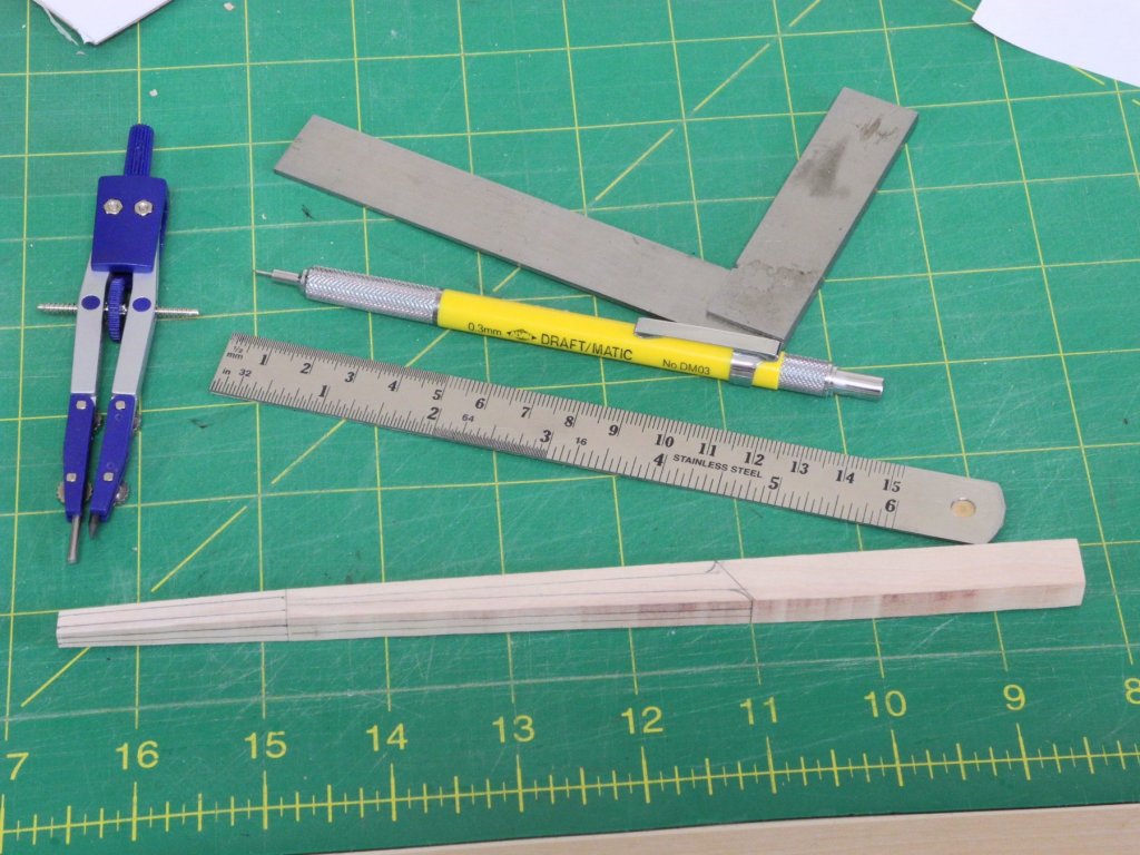
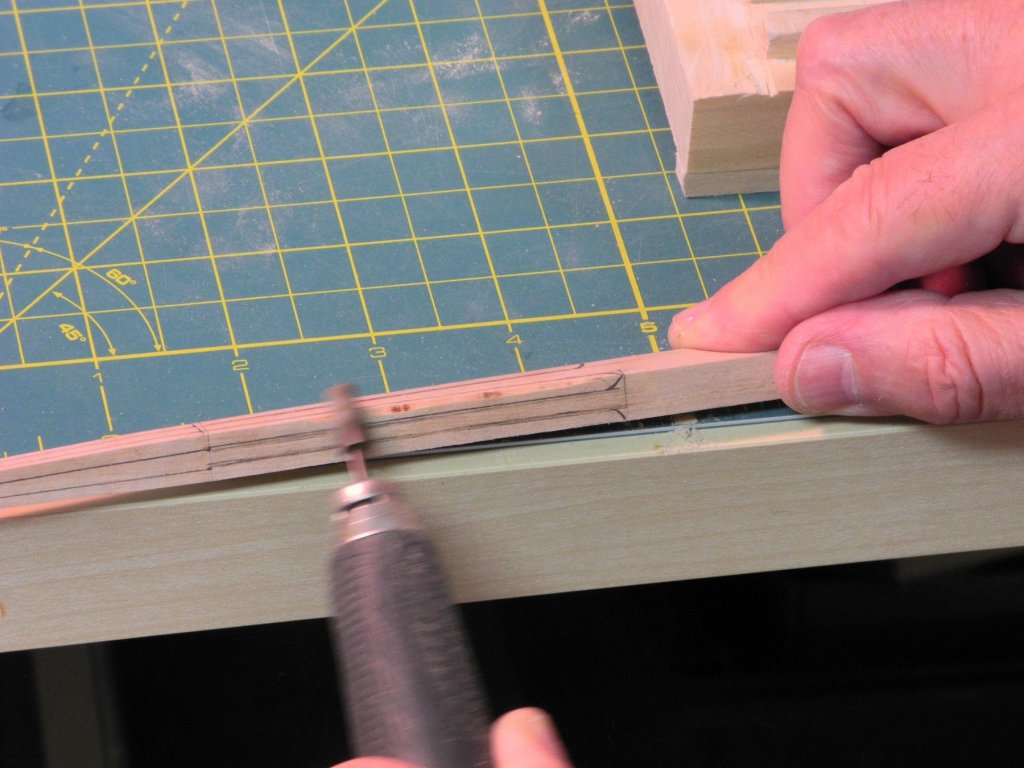
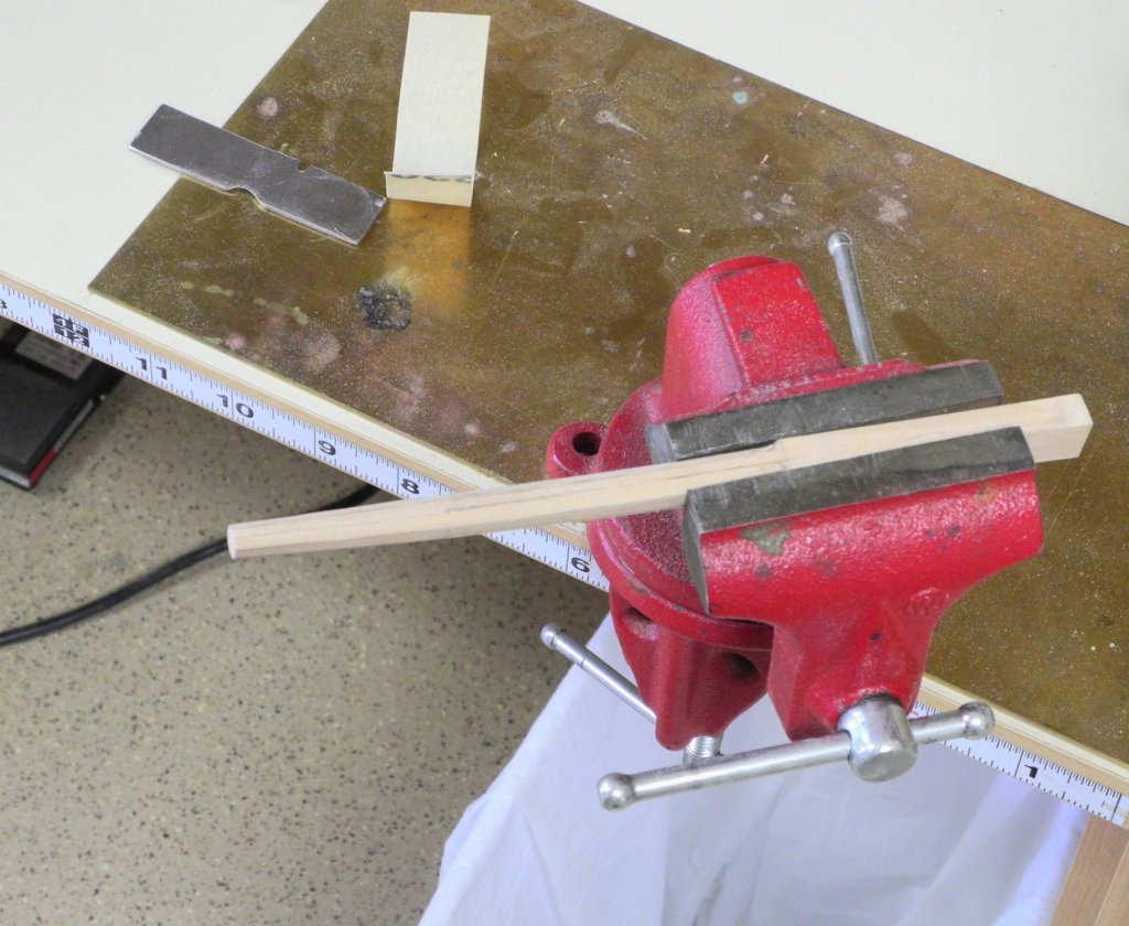
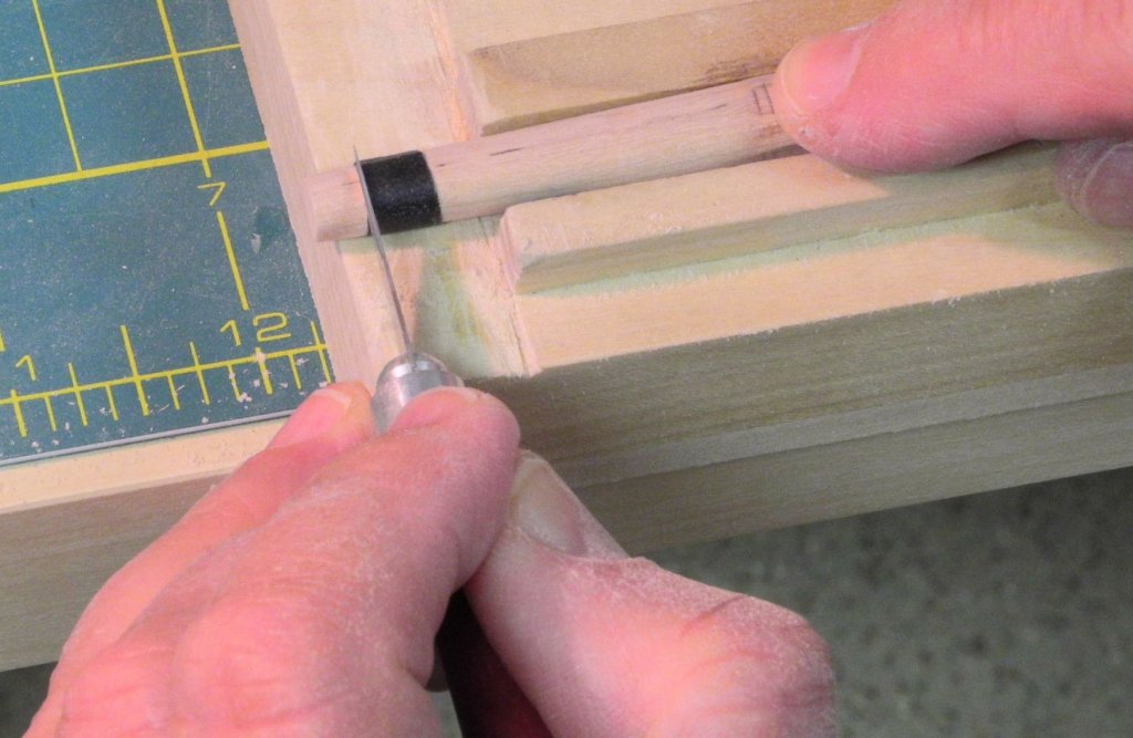
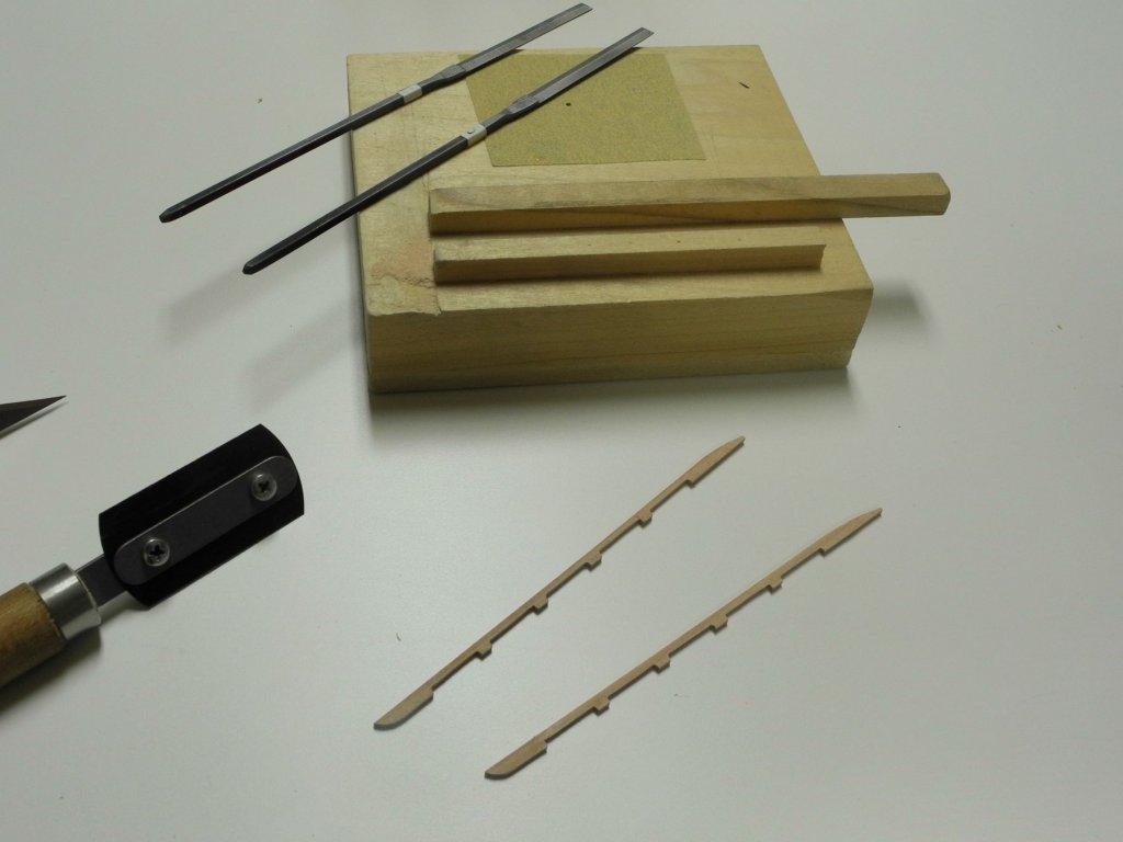
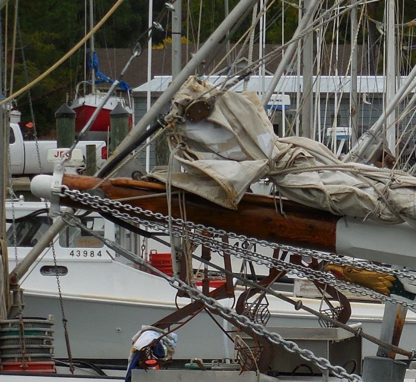
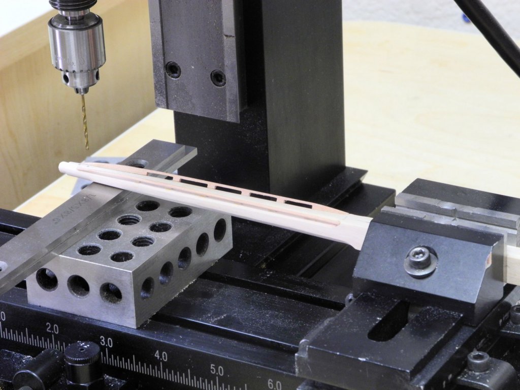
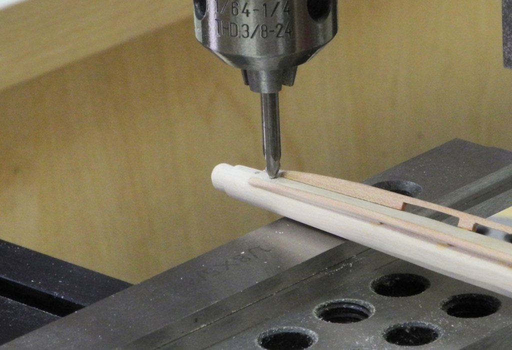
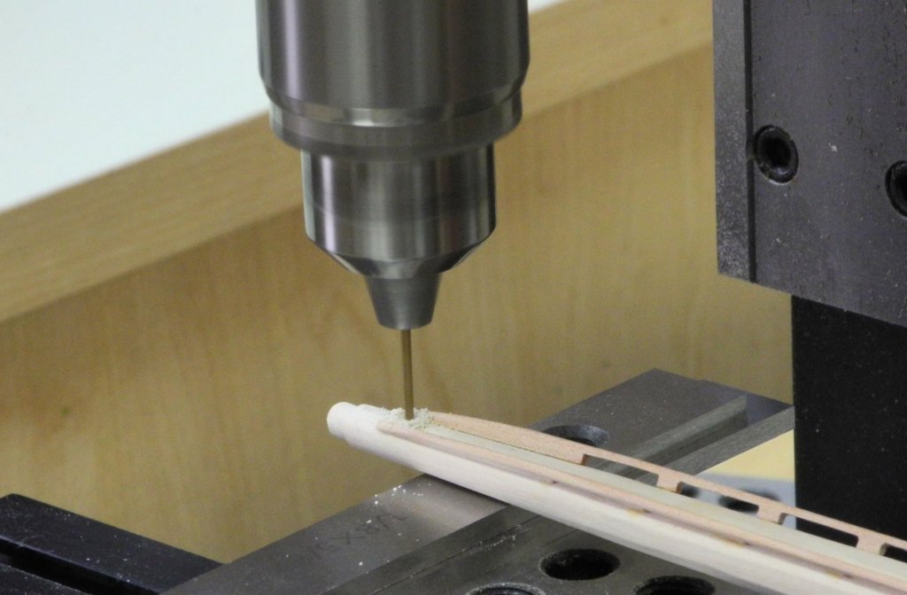
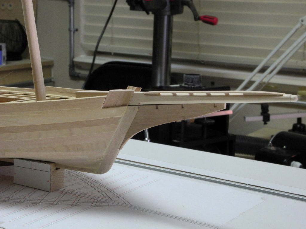
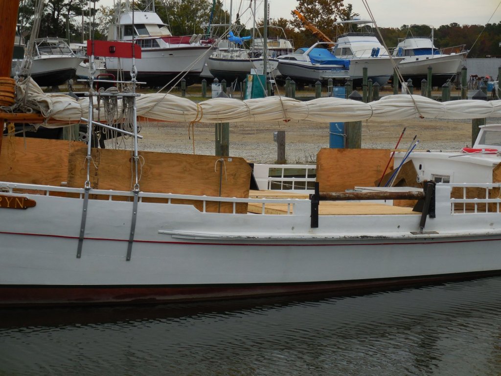
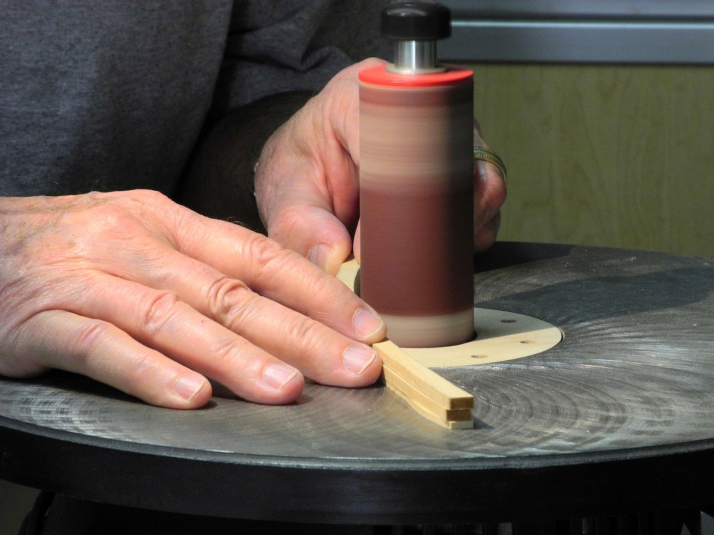
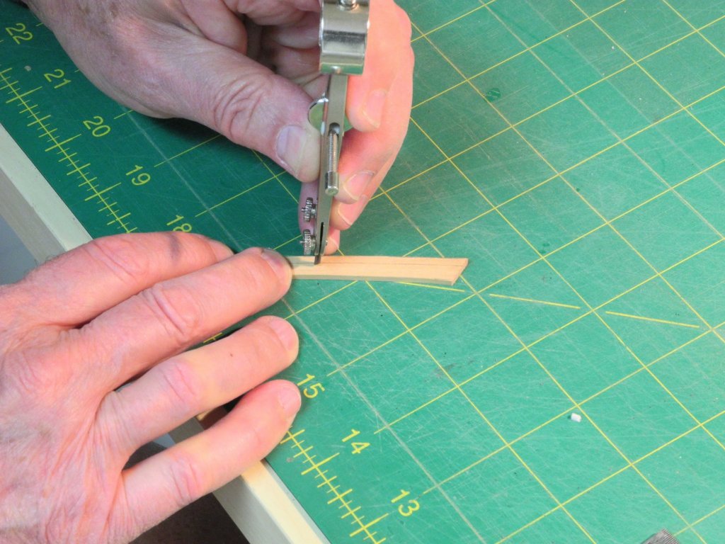
Part 31 – The Bowsprit Kathryn’s bowsprit is 20 feet long, and has straight sides (and top and bottom) for most of its length. Forward of the stem it is shaped as an octagonal, even though not all sides are equal. The final 5 forward-most feet of the bowsprit are rounded and tapered from 10 inches to 7 inches. The final 6 inches are reduced to 4.5” diameter and rounded at the end. This is where the bowsprit band will sit. The construction of the bowsprit started with shaping the square stock to the overall dimensions. Then a compass was used to mark the boundaries of the cuts for the octagonal shapes. A rotary tool was used to make the diagonal cuts to roughly form the octagonal shapes. Files were used to clean up these shapes. A rounded scraper, followed by sandpaper, was used to form the rounded front of the bowsprit. Chart tape was then wrapped around the end of the bowsprit to indicate the beginning of the reduced end of the bowsprit, and a stop cut was made with a hobby knife along the boundary of the tape. The end of the bowsprit was then reduced to achieve the diameter that would fit within the bowsprit band, using the knife and files. A brass tube that would be used for the band was used to check the diameter during shaping. The bowsprit has ‘walking boards’ along the top edge, on each side of the bowsprit. These were fitted sometime after initial construction, and were present during the HAER survey (and are present today). These are fairly small, and I used 3/64 stock to make them. I started by spot-gluing two pieces of stock together, using school glue. This allowed me to shape both walking boards at the same time. Unfortunately, I didn’t take photos during the shaping process, but the following photo shows the tools used. After constructing and attaching the walking boards, I realized that two holes needed to be drilled through the bowsprit to accommodate the forestay (which passes through the bowsprit) and an eyebolt for the jib halyard, as shown in the following photo of Kathryn. This would have been much easier if the drilling was done before any shaping of the bowsprit, but since the bowsprit still had flat vertical sides it didn’t present a major problem. The bowsprit was placed in the milling vise, and was checked for proper alignment. The end of the bowsprit that was to be drilled was supported so that the pressure of drilling did not cause the bowsprit to bend. Since the area to be drilled was round, a centering drill was used to start the hole. And the hole was then drilled through the bowsprit. The bowsprit will be painted before any hardware is installed on it, and will not be permanently installed until a later stage. The following photo shows the bowsprit temporarily installed. We’ll be leaving on a short road trip to California tomorrow to escape the heat for a few days. When we return it will be time to address the permanent mounting of Kathryn, and then to begin the process of painting the hull. Hope everyone is well and enjoying the summer - thanks for the comments and the 'LIKE's!


- 878 replies
-
- 26
-
-
Hi Druxey - I think you may have aimed this my way instead of Ed's. And yes, I meant to say 'tick strips' - I may have had an involuntary muscle twitch on the keyboard.
-
Ed - a question on the tool you've made for marking the octagonals: is the 'scriber' a small point that scratches the line into the spar?
- 3,618 replies
-
- 2
-
-
- young america
- clipper
- (and 1 more)
-
Thanks Ed. I've been thinking of making a tool like you used in your latest YA post, but with minimal spars on Kathryn I haven't tried it yet. I first saw a similar tool in an article by Roger Cole.
-
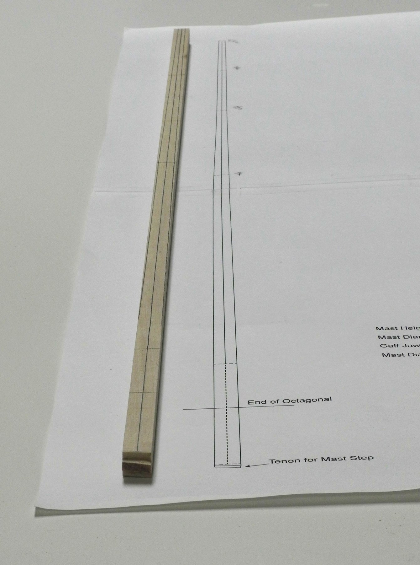
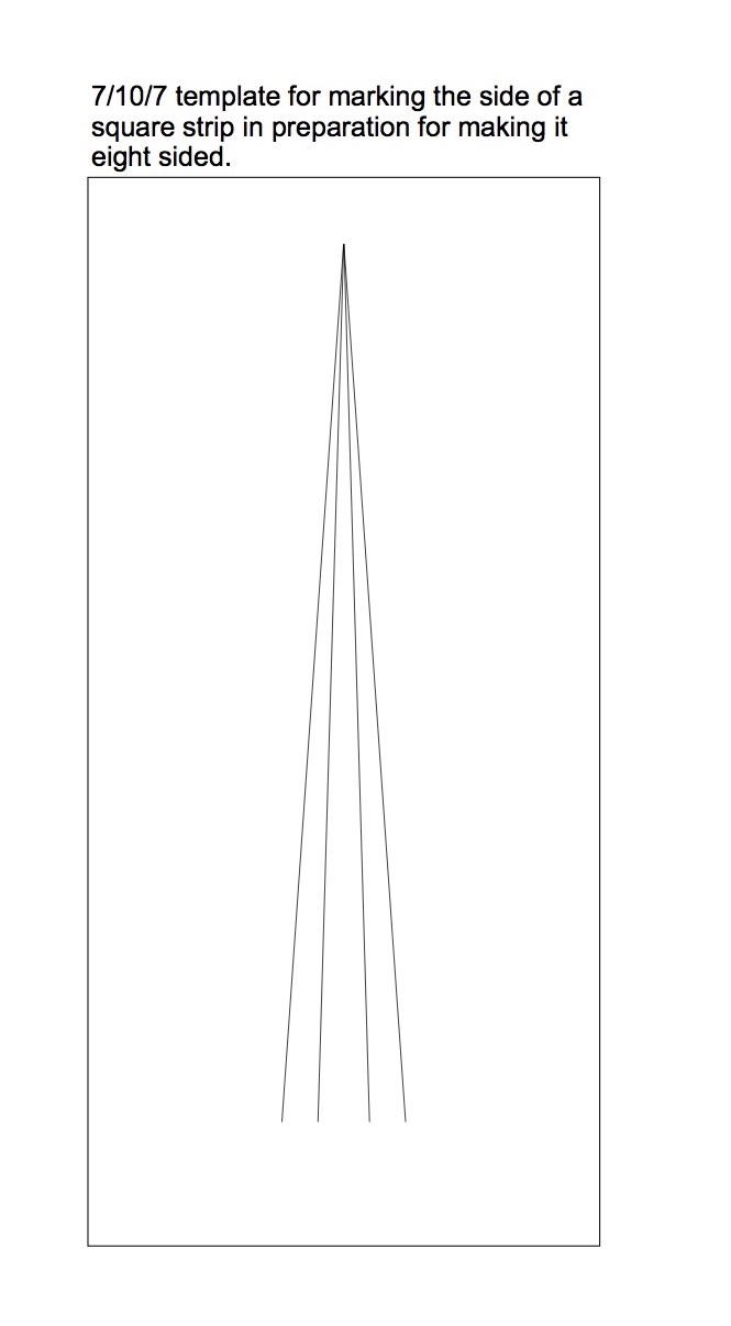
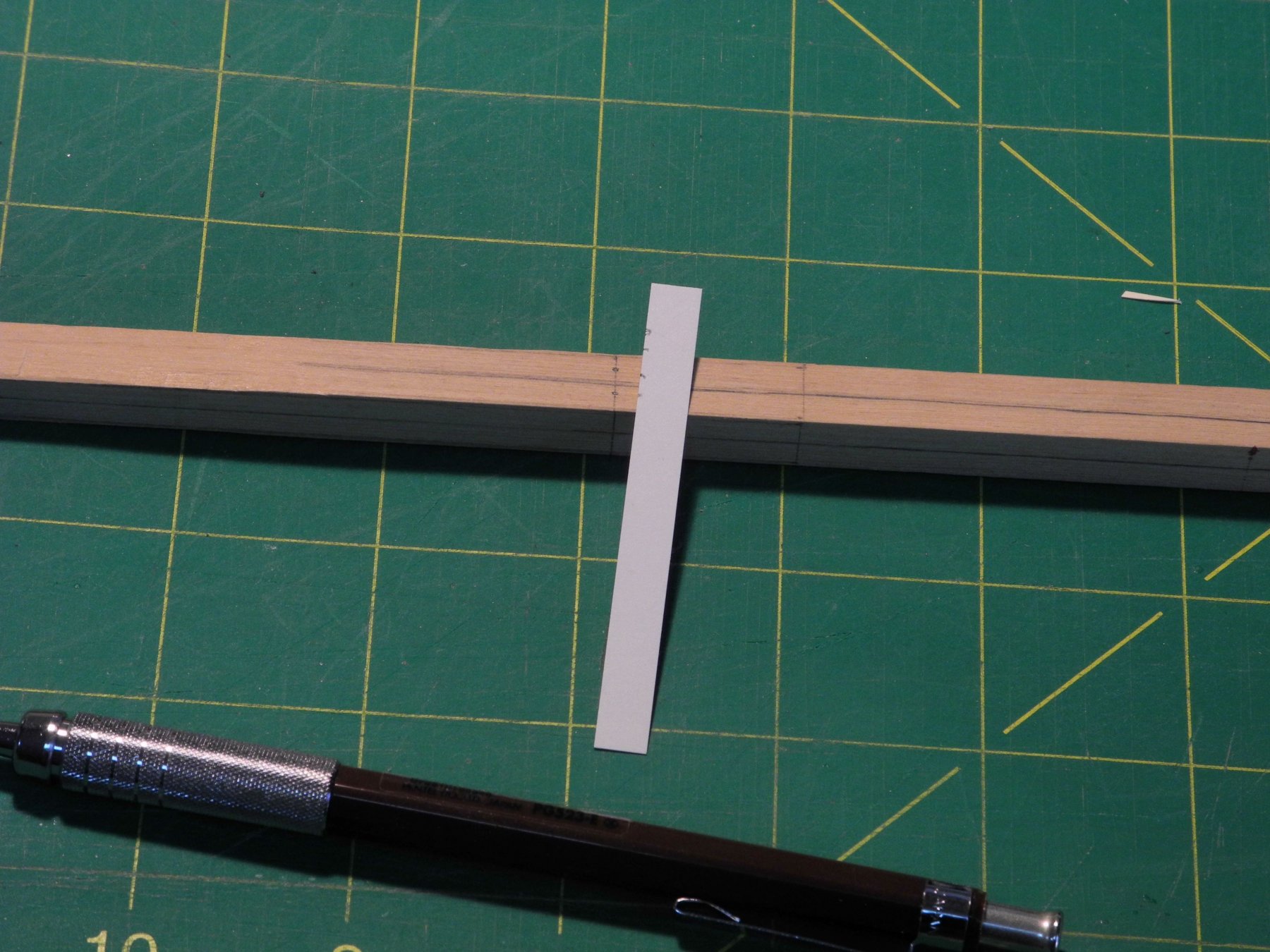
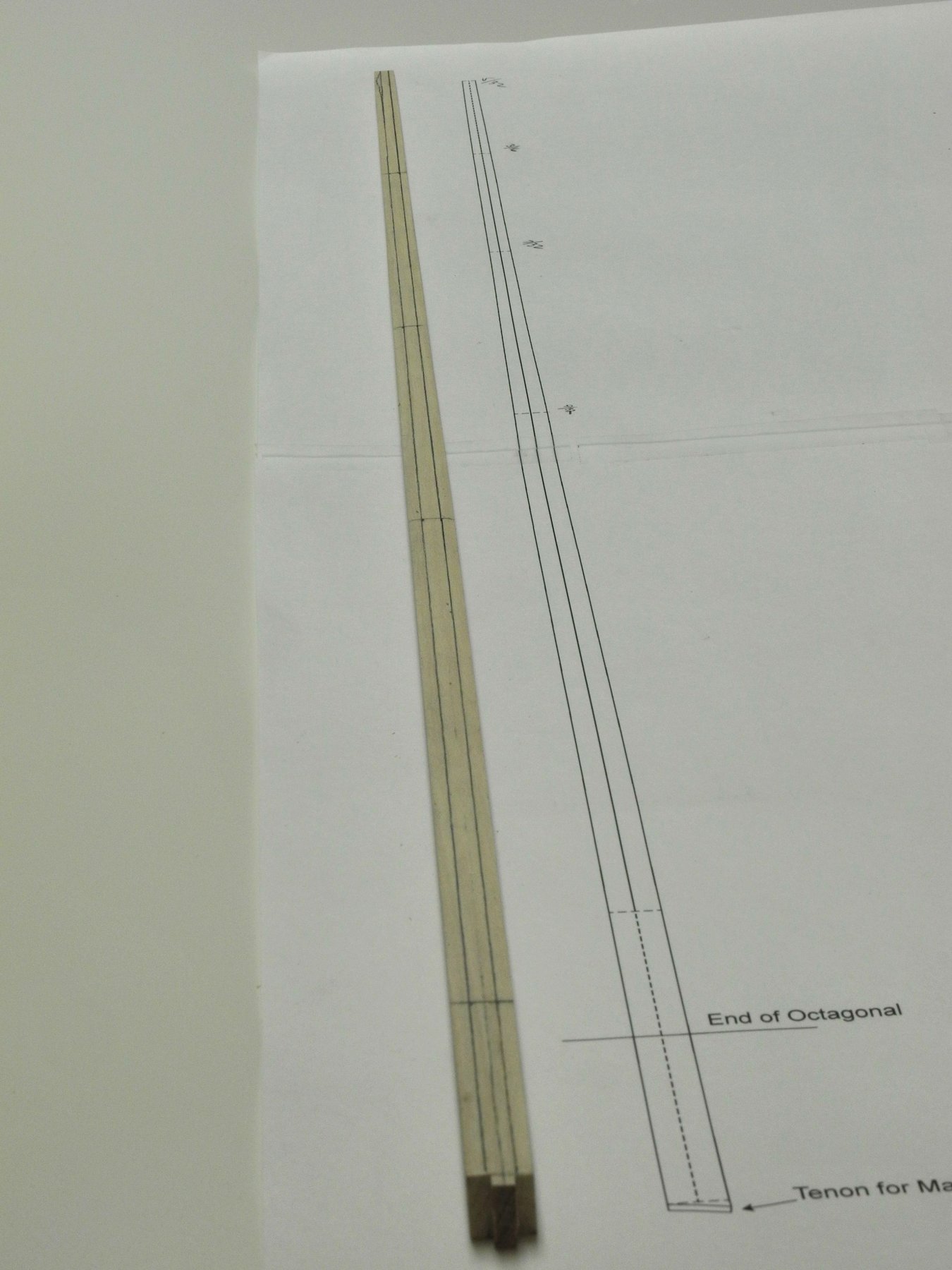
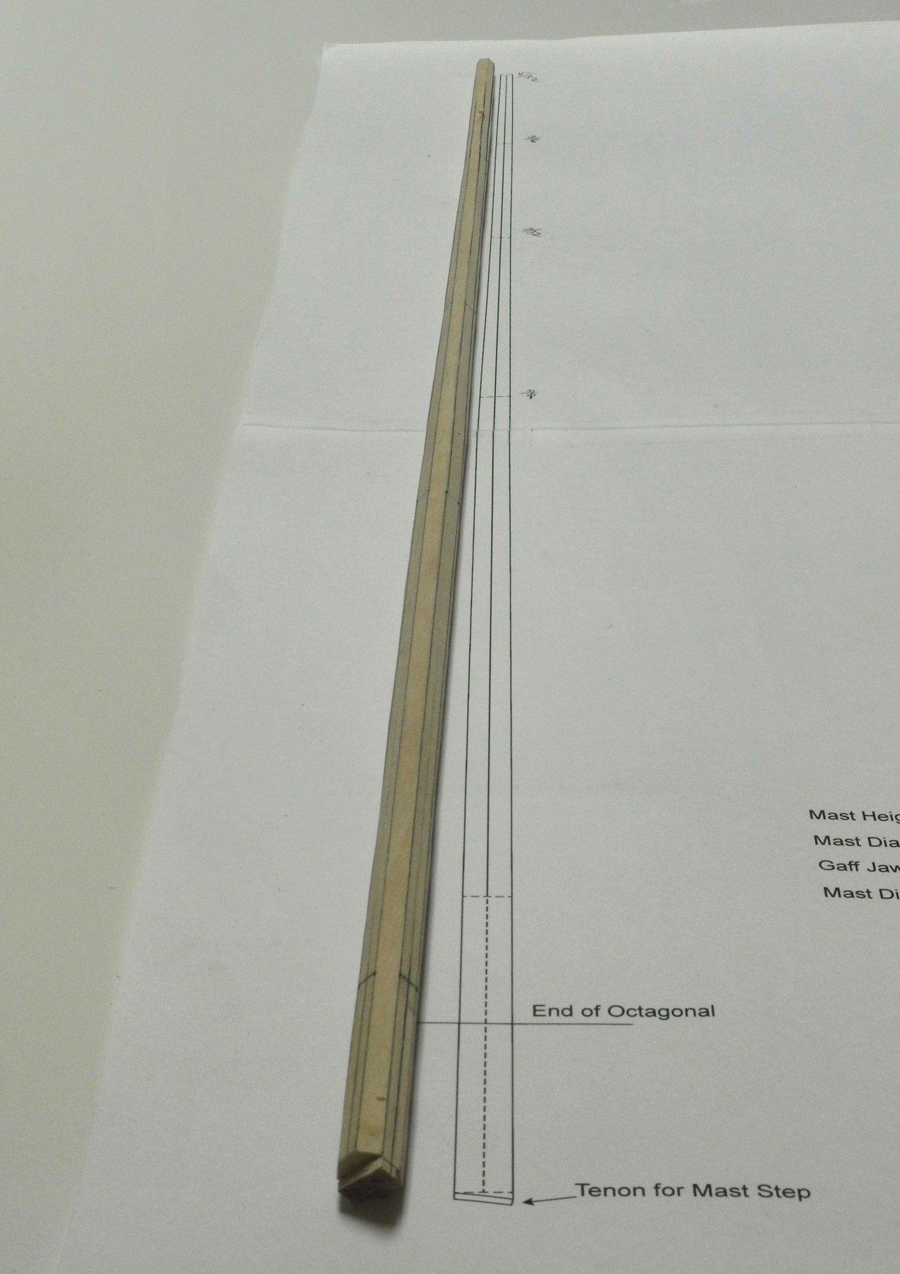
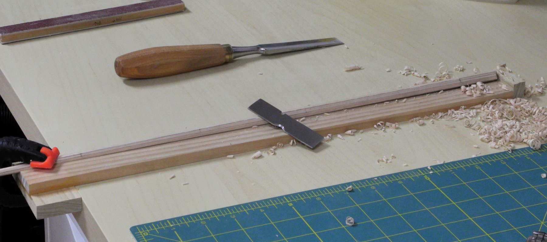
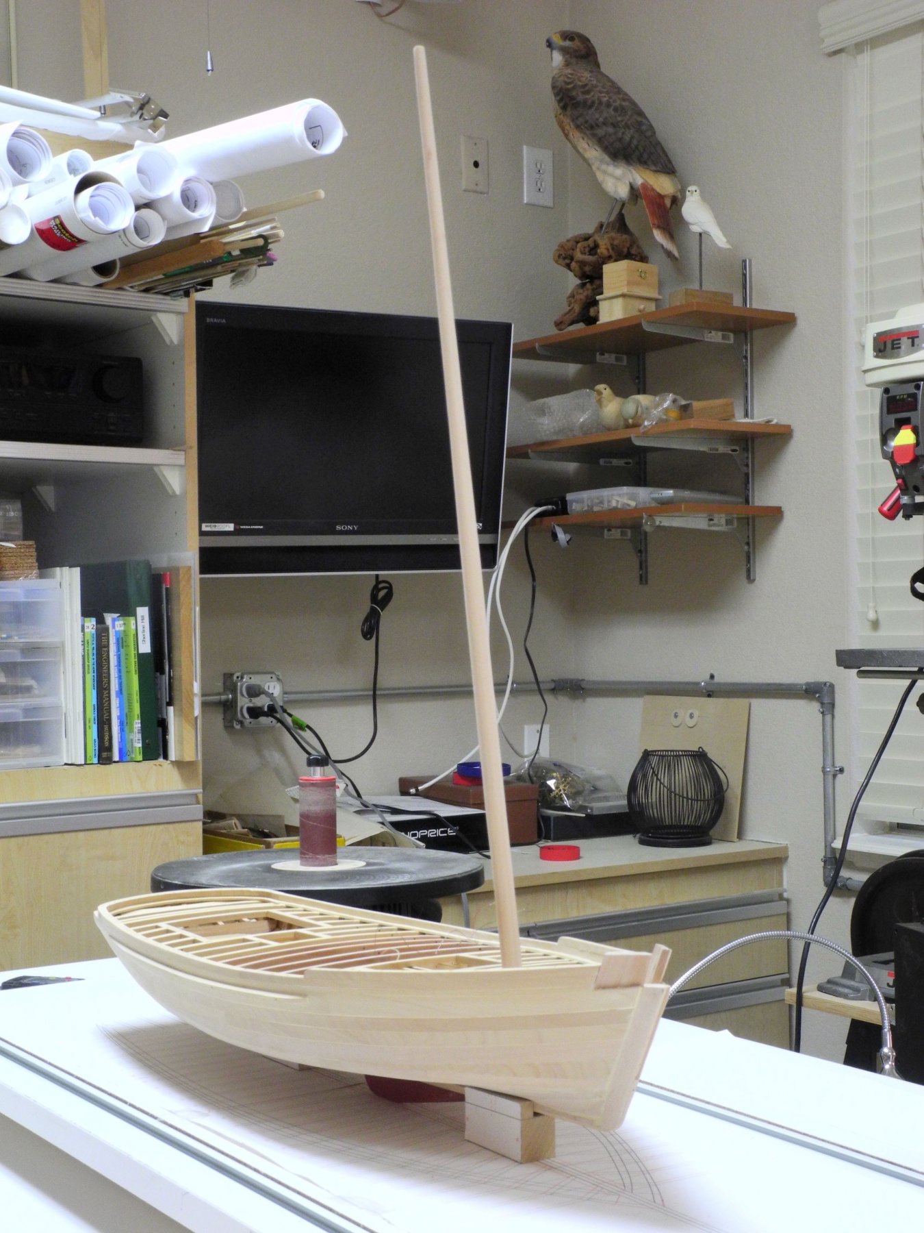
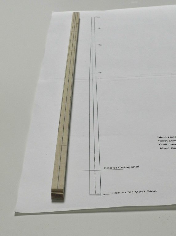
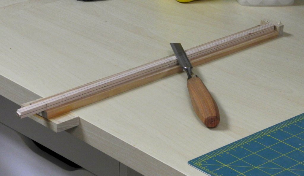
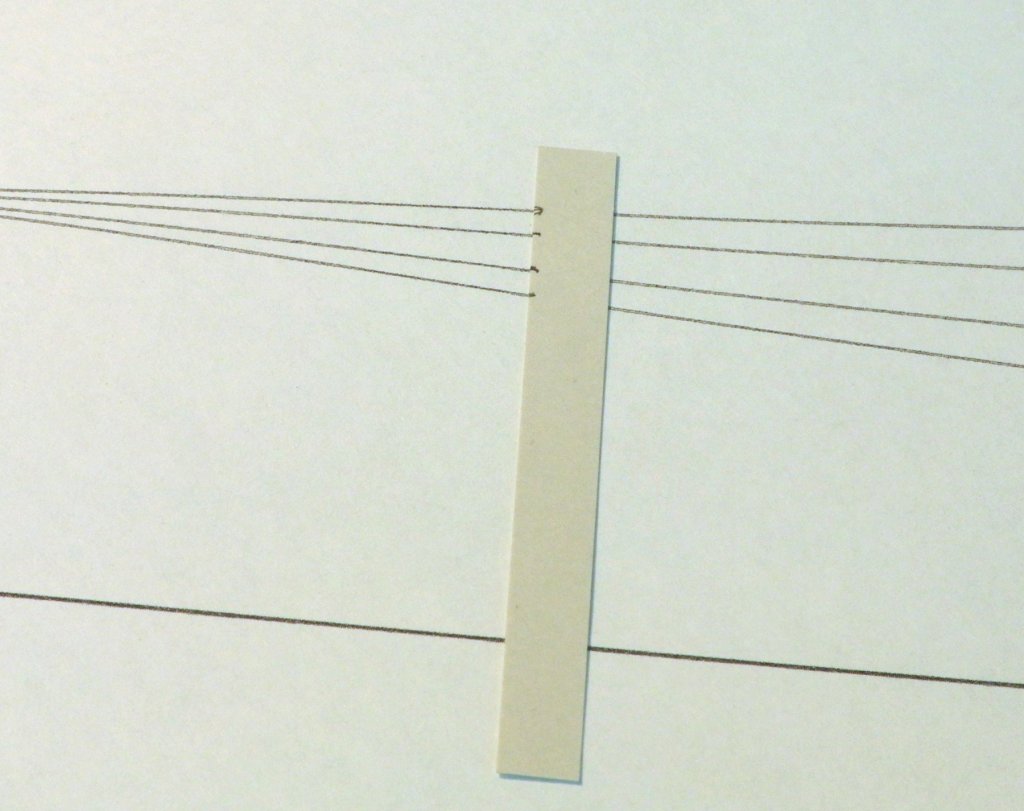
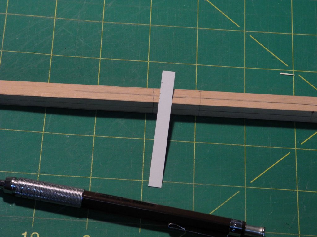
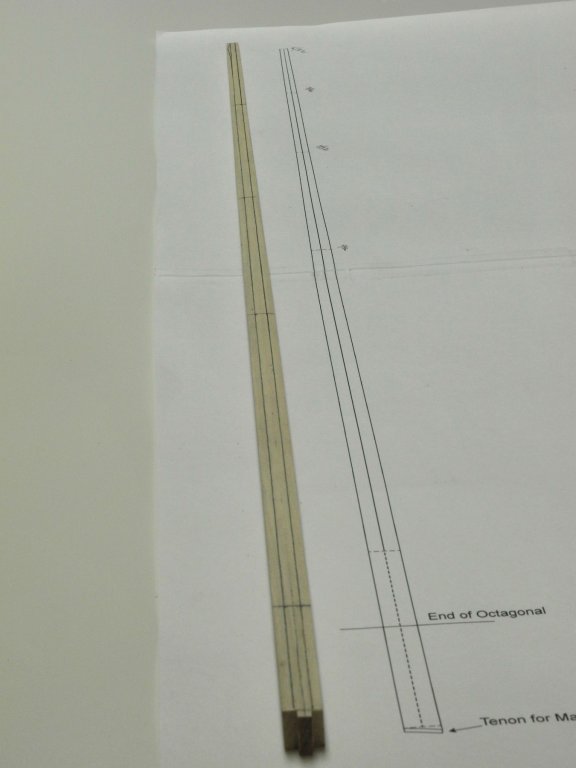
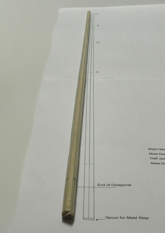
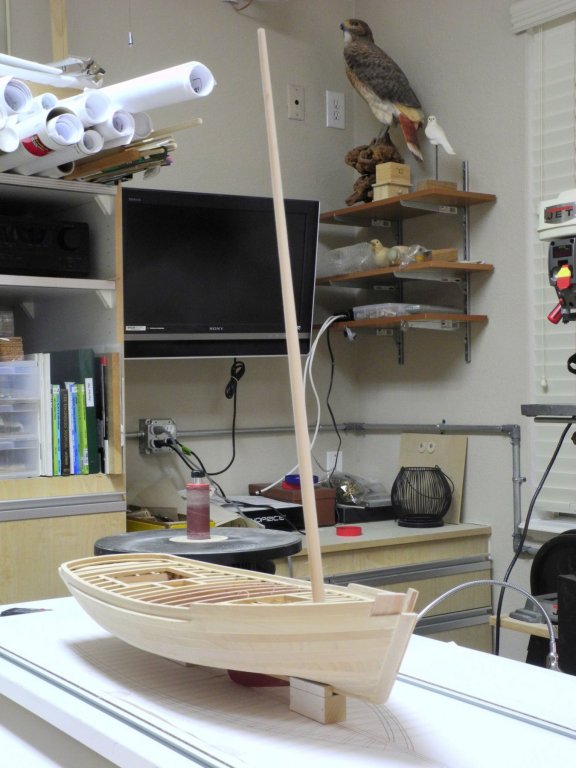
Part 30 – The Mast Kathryn’s single mast is 63 feet tall, the diameter at the foot of the mast is 13.5”, and the diameter at the mast top is 5.7” (all measurements taken from the HAER drawings). The lower portion of the mast, from deck height down to the foot, is octagonal. The measurements from the drawing were transferred to an appropriate piece of madrone, as in the following photo. The mast was shaped using a chisel and a holding jig. A 7-10-7 drawing was used to shape the mast as an octagonal. First a line was drawn across the width of the mast at several intervals along the length of the mast. At each interval the width of the mast was indicated on a tic strip and, using the 7-10-7 drawing, the placement of the octagonal cuts was marked on the tic strip. The appropriate marks were made on the mast This was done on all four sides of the mast. Lines connecting all of the octagonal marks were then drawn on the mast. The chisel was used to remove the material outside the octagonal lines. A round scraper was used to form the round shape of the mast. I’ve found that it’s easier to keep the mast round using a scraper than when using sandpaper for this initial shaping. After finish sanding the shaping of the mast is completed. The following photo shows the mast temporarily installed on Kathryn. The next step is to shape the bowsprit, which will be the topic of the next post.


- 878 replies
-
- 22
-
-
Ed, you make complex work appear routine, and the explanations of the process are perfect. I learn something new with almost every post. Thank you!
- 3,618 replies
-
- 4
-
-
- young america
- clipper
- (and 1 more)
-
Hi Ron - yeah, my scrap box still has some room in it, but there are still lots of opportunities for do-overs. Thanks Patrick - I'm enjoying this build. Kathryn is one of the nicer skipjacks and I'm trying to do right by her.
-
Hi Popeye - thanks! I'm sure there are lots of other approaches, but I felt most comfortable with this one. Thanks Tom. Installing the rails is still a long way off, but I'm looking forward to seeing how they come out.
-
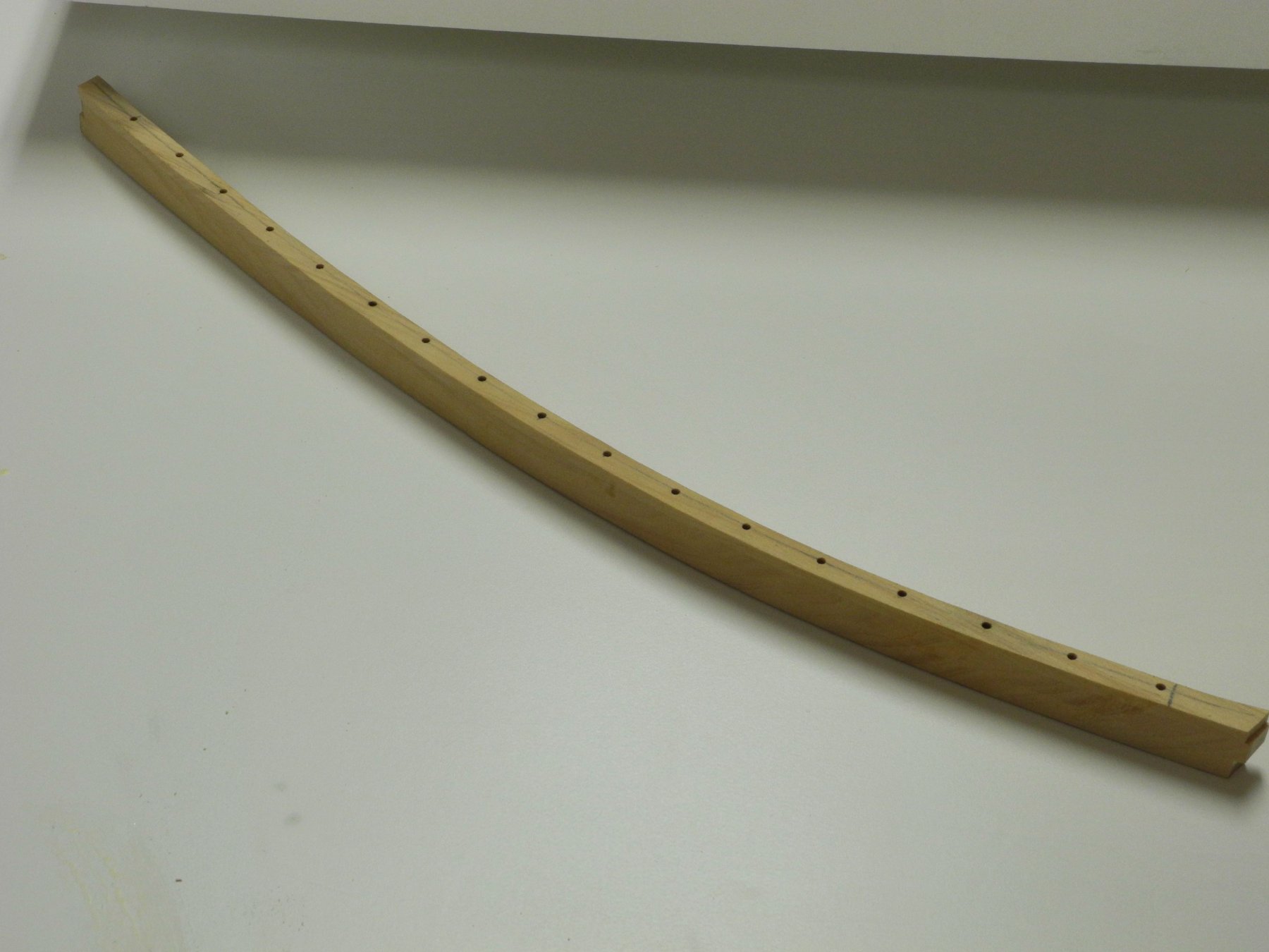
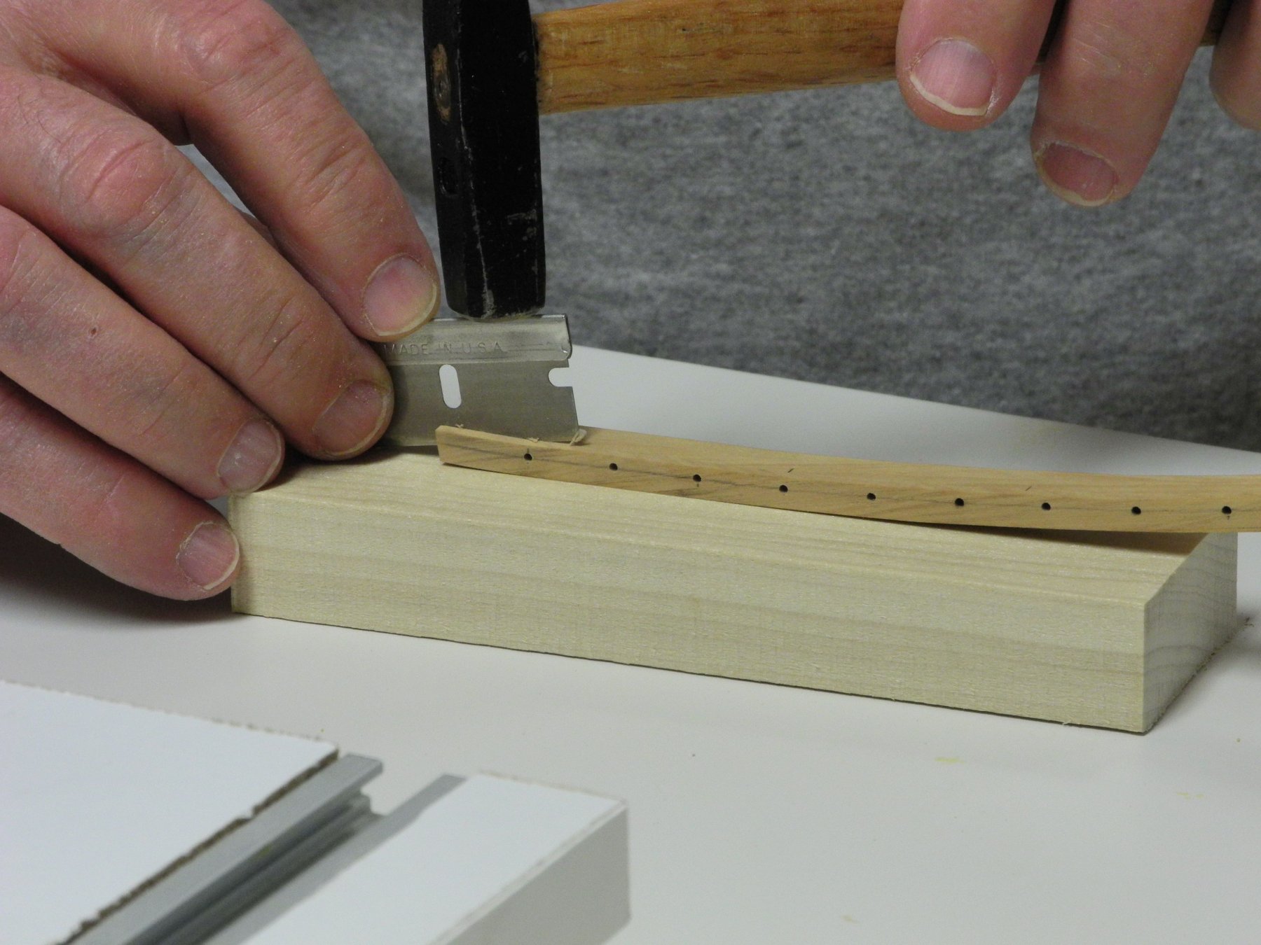
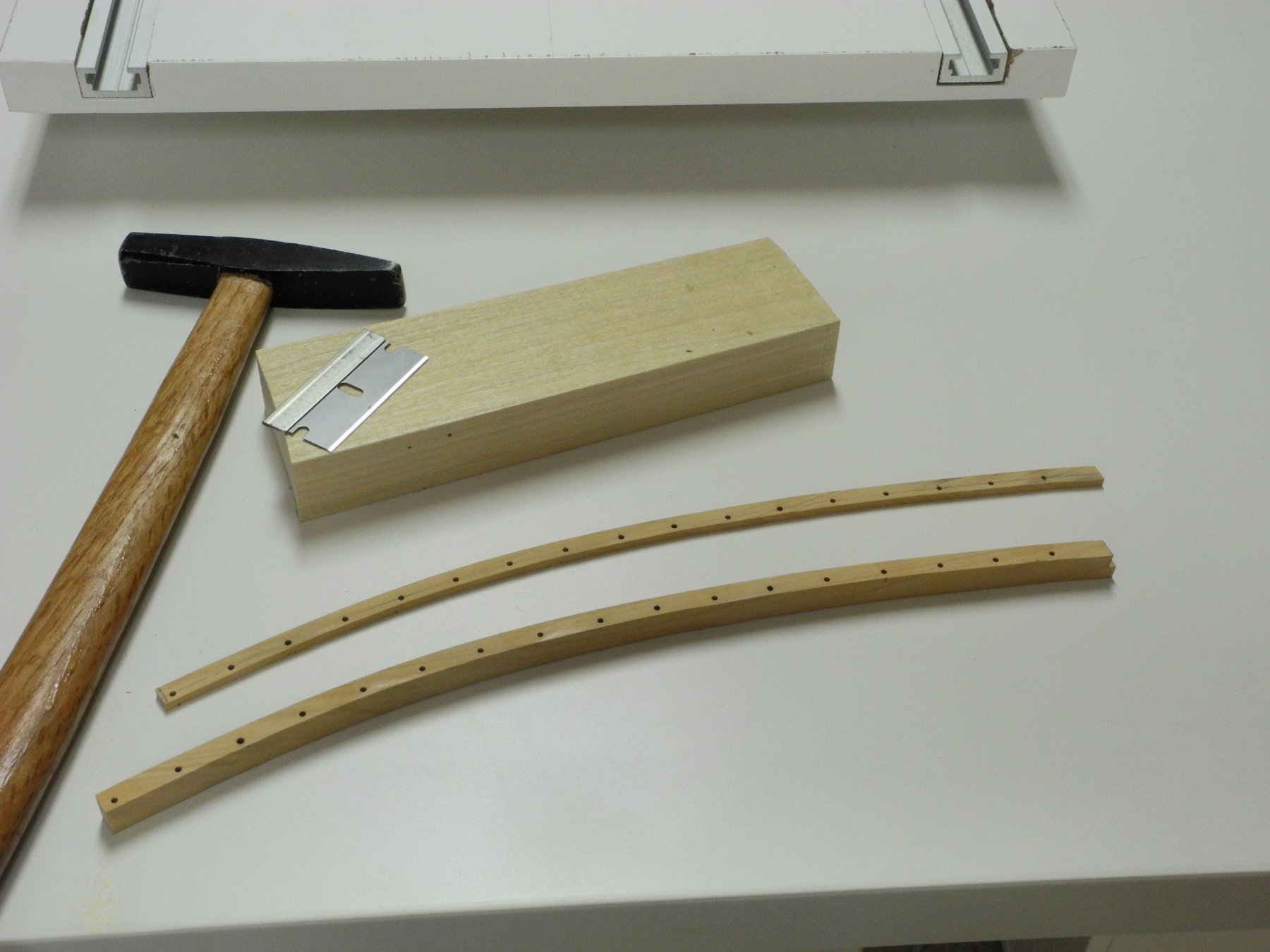
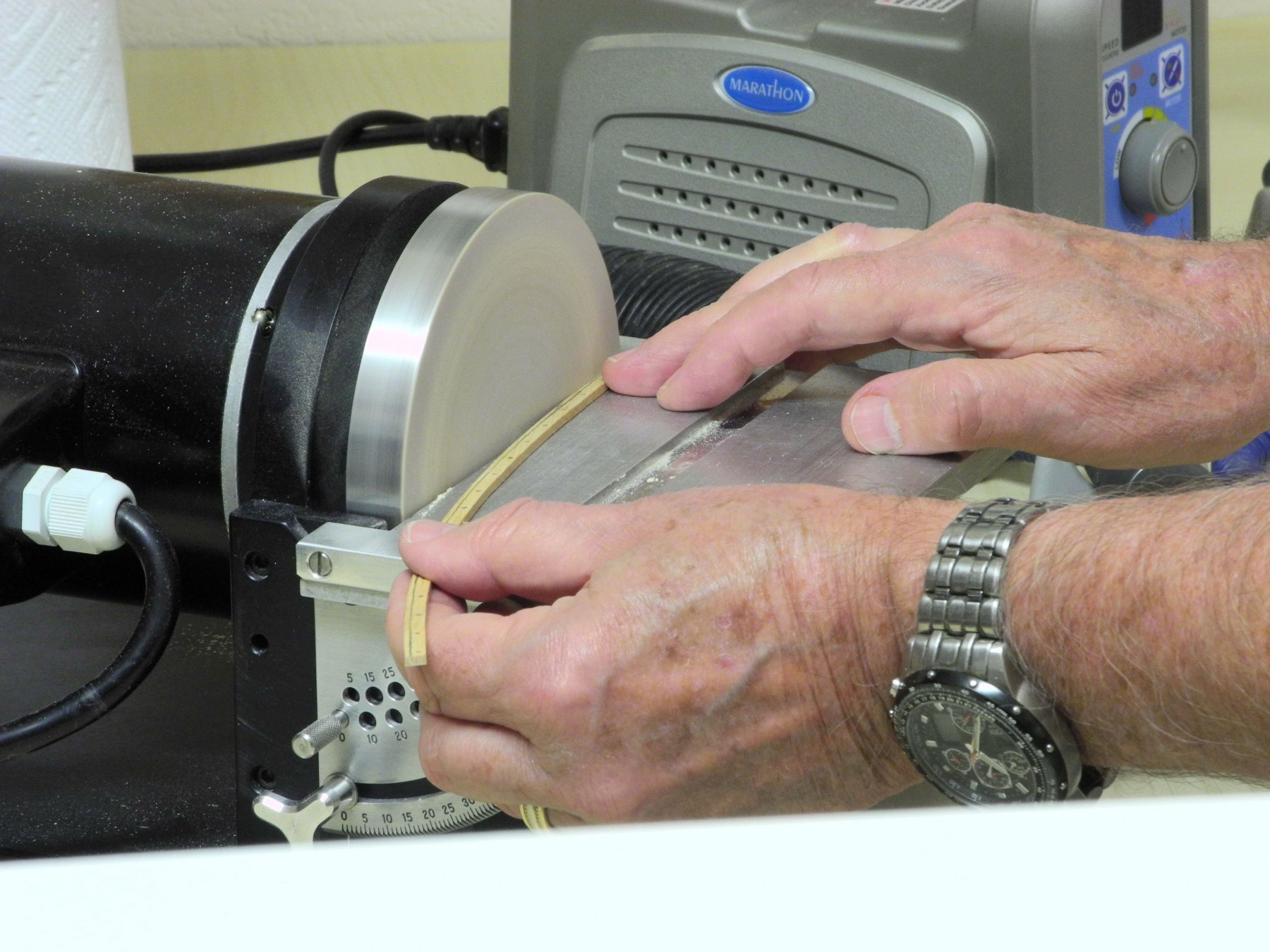
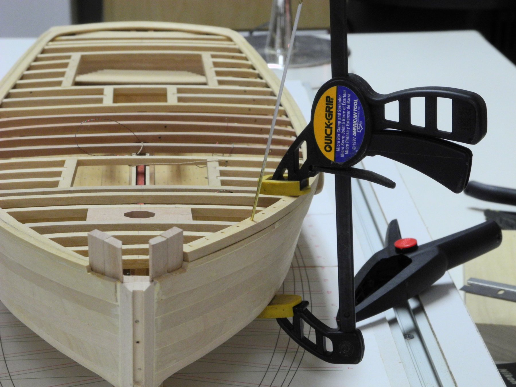
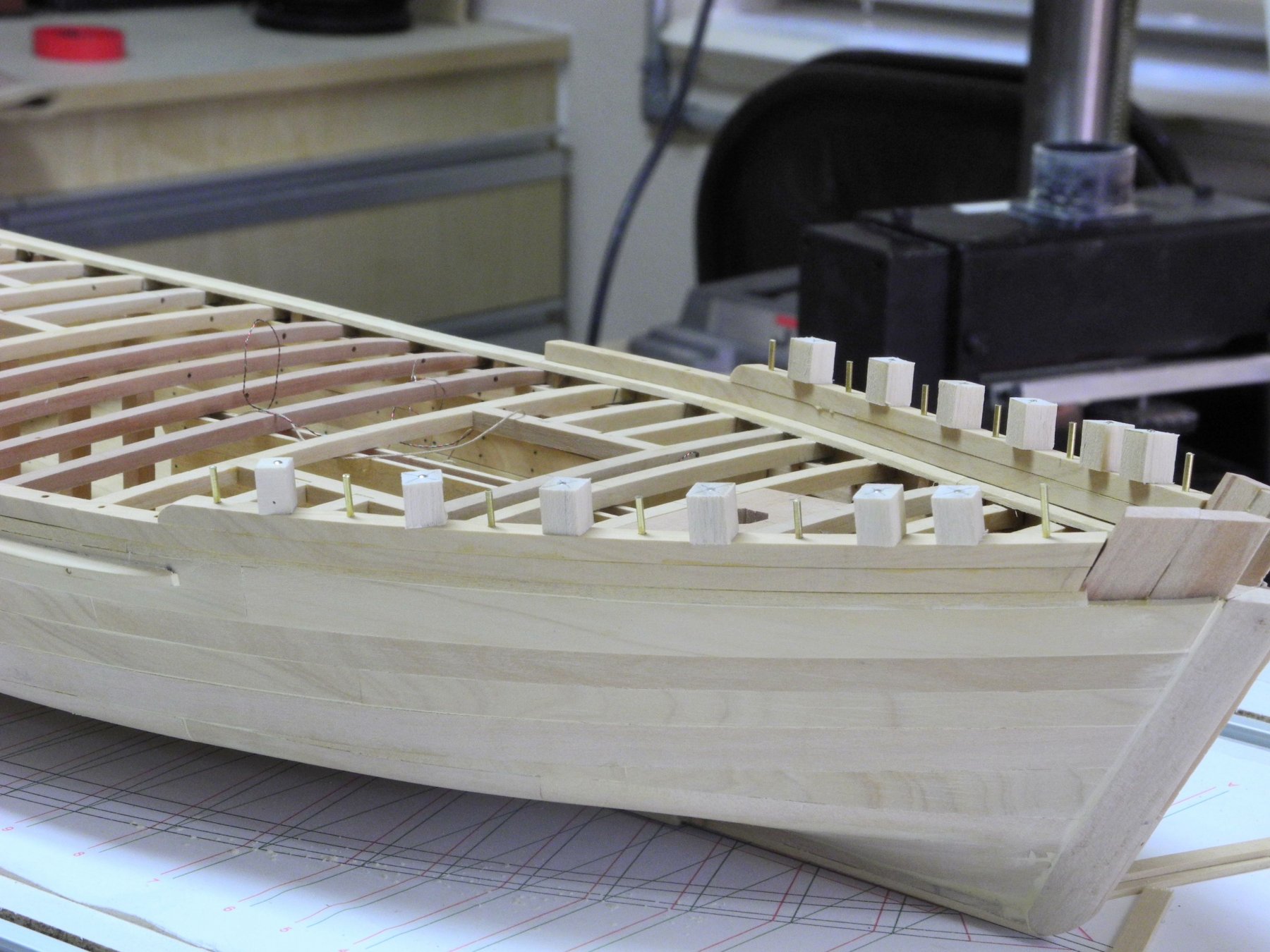
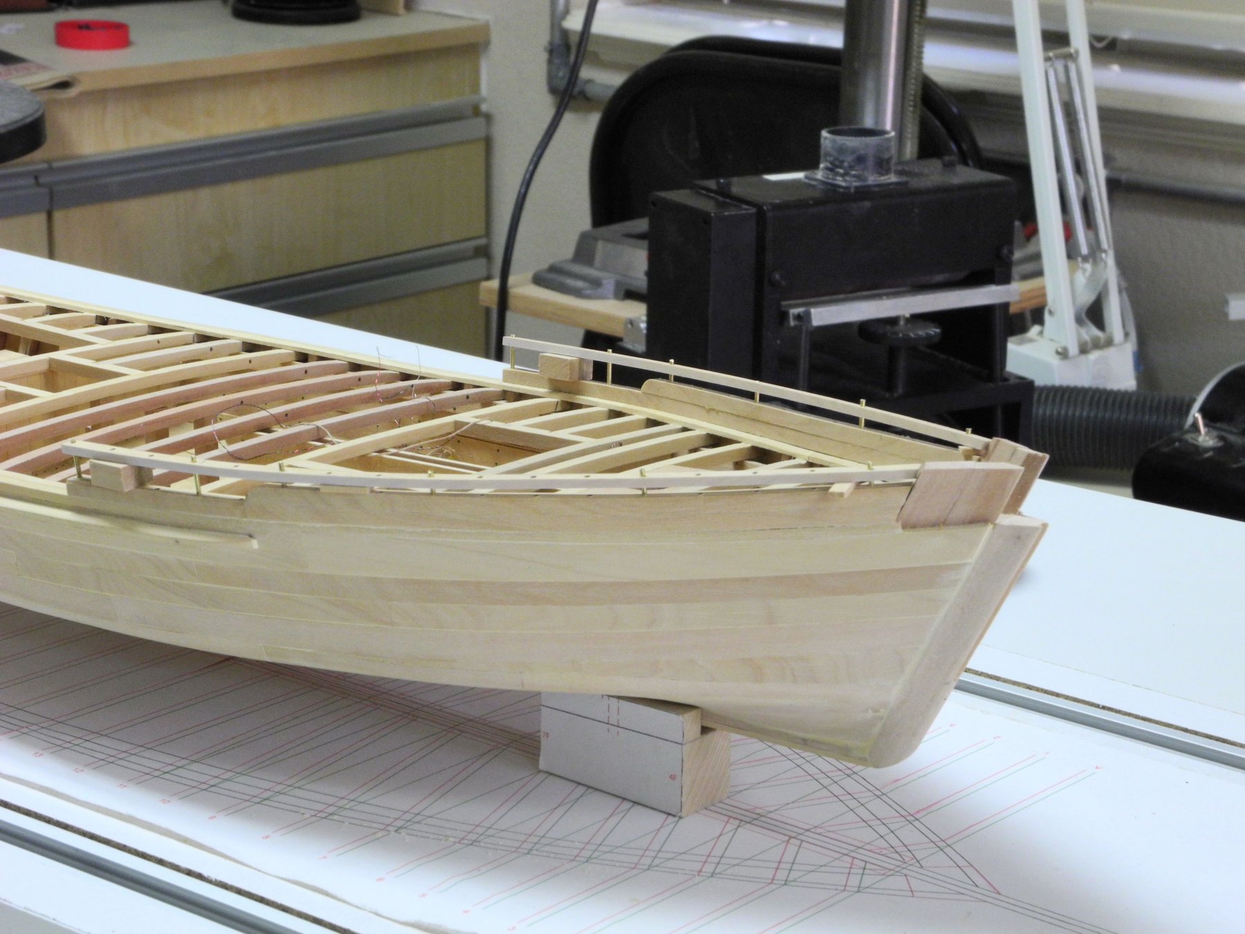
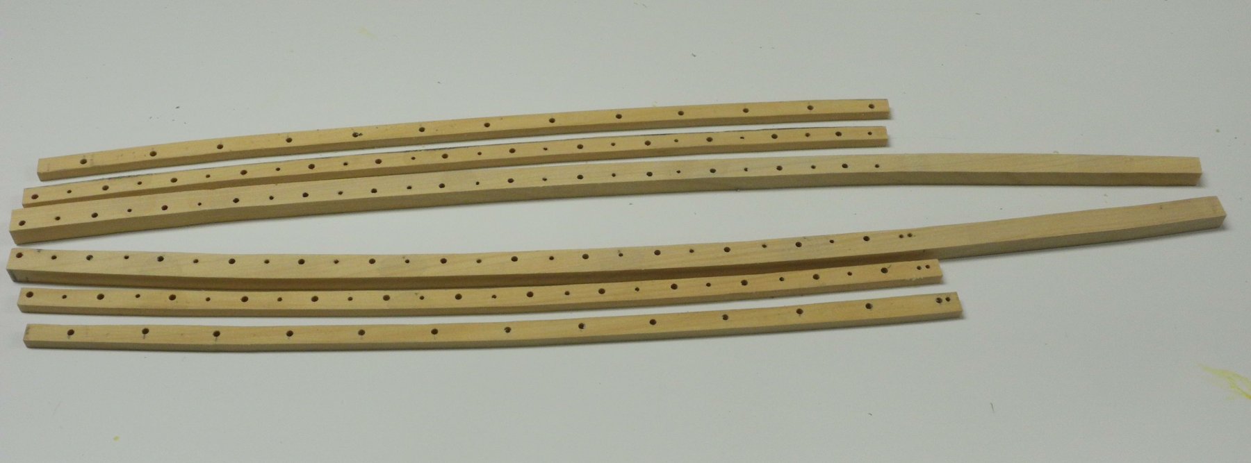
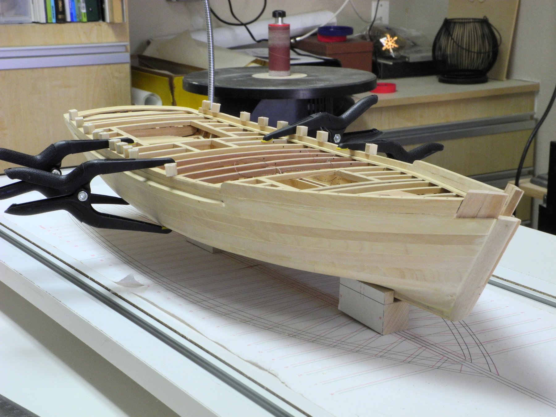
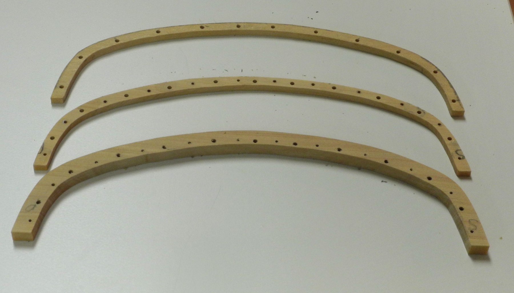
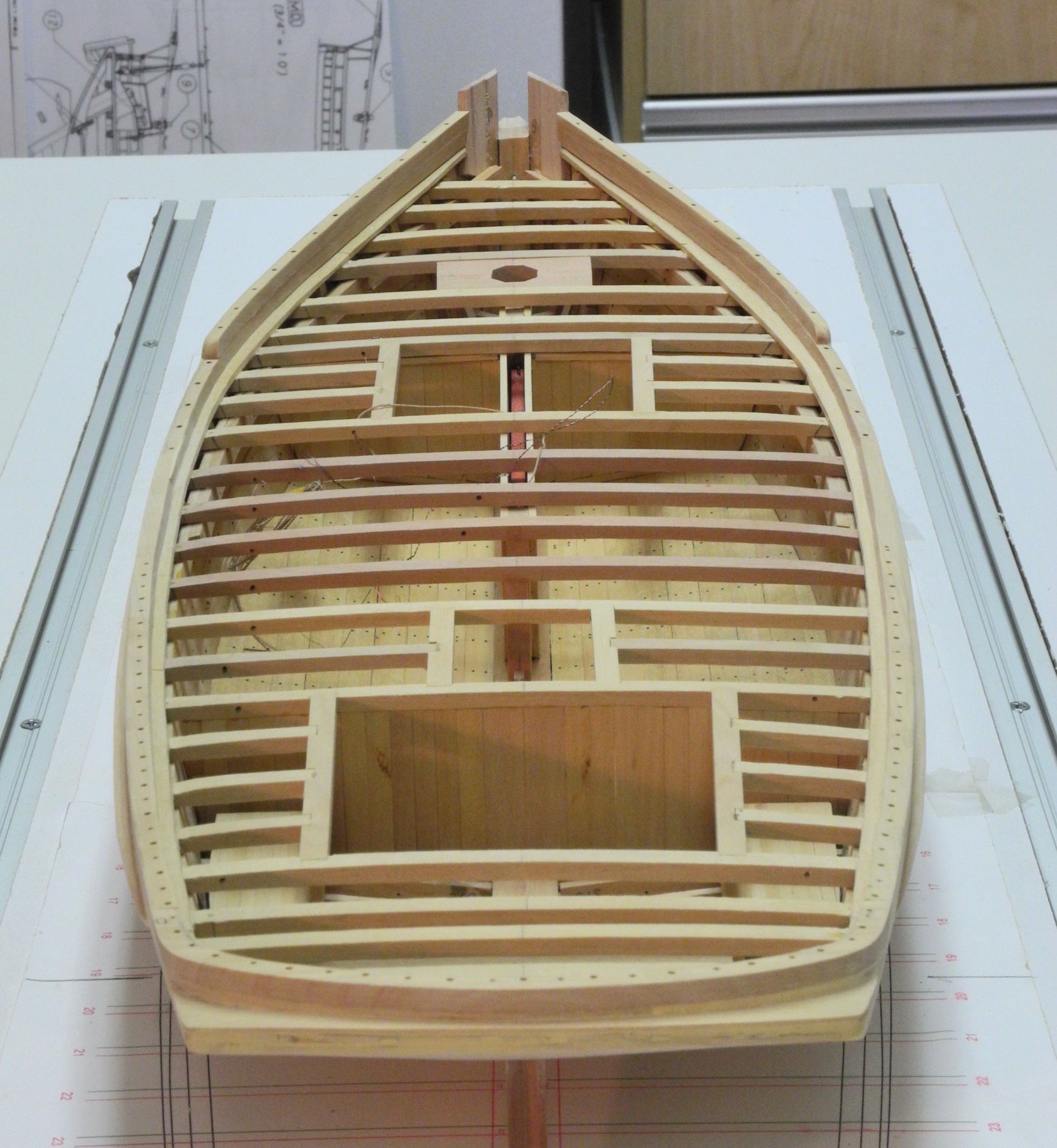
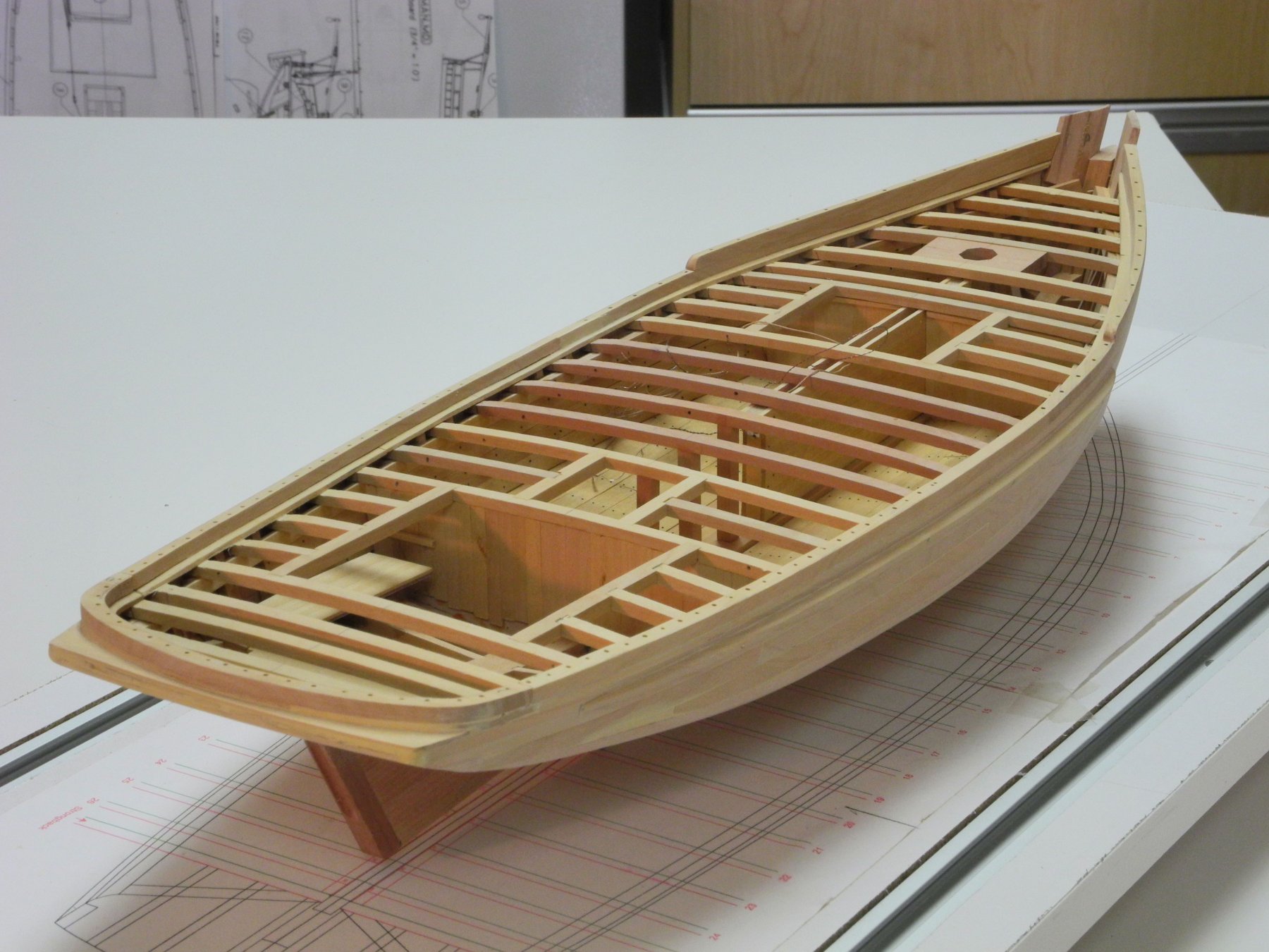
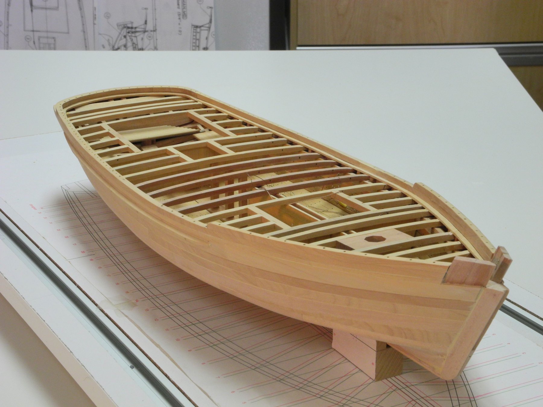
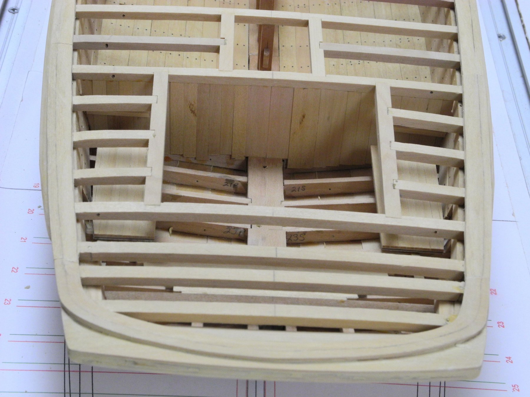
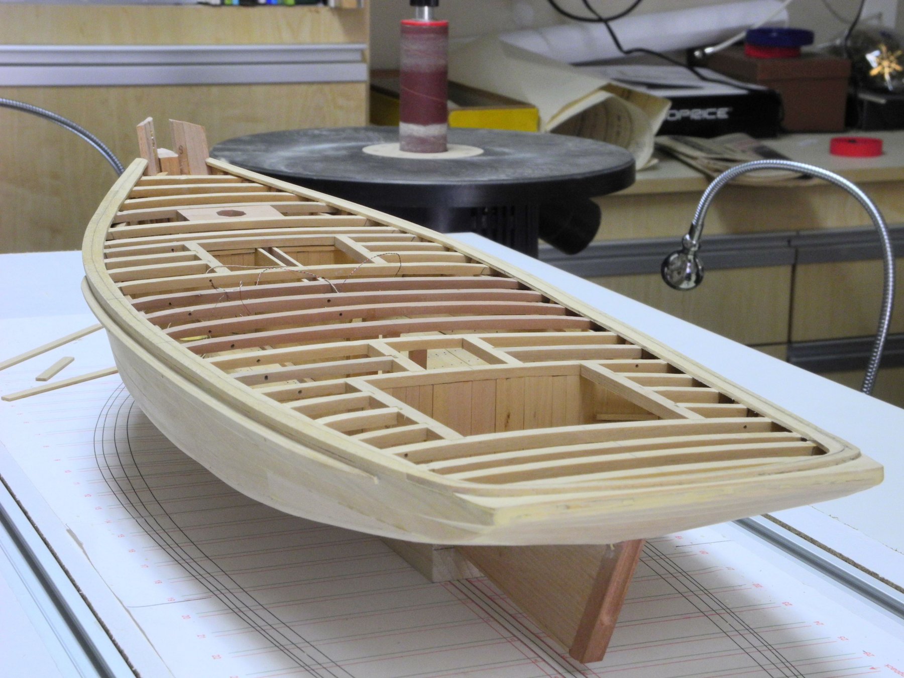
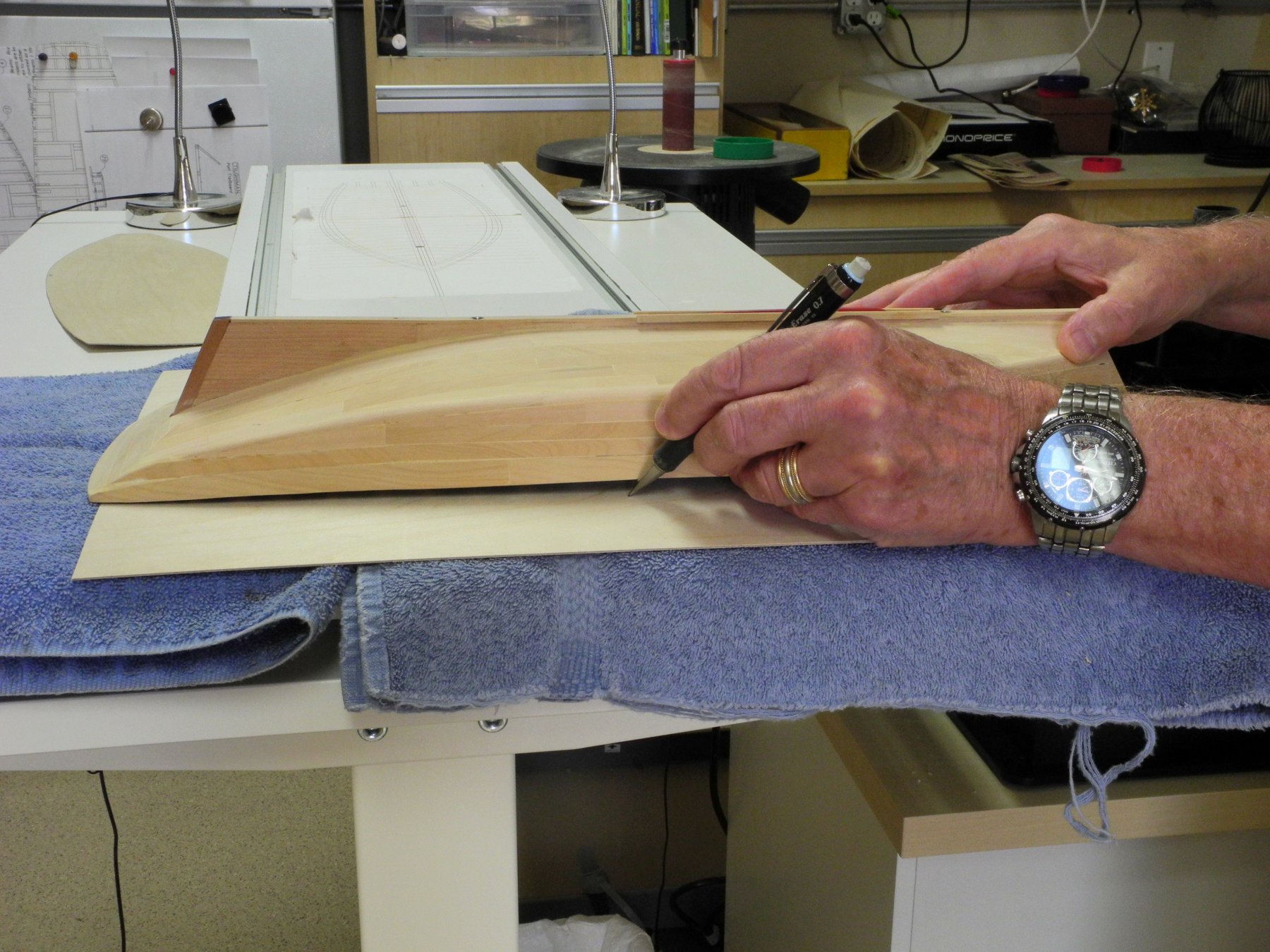
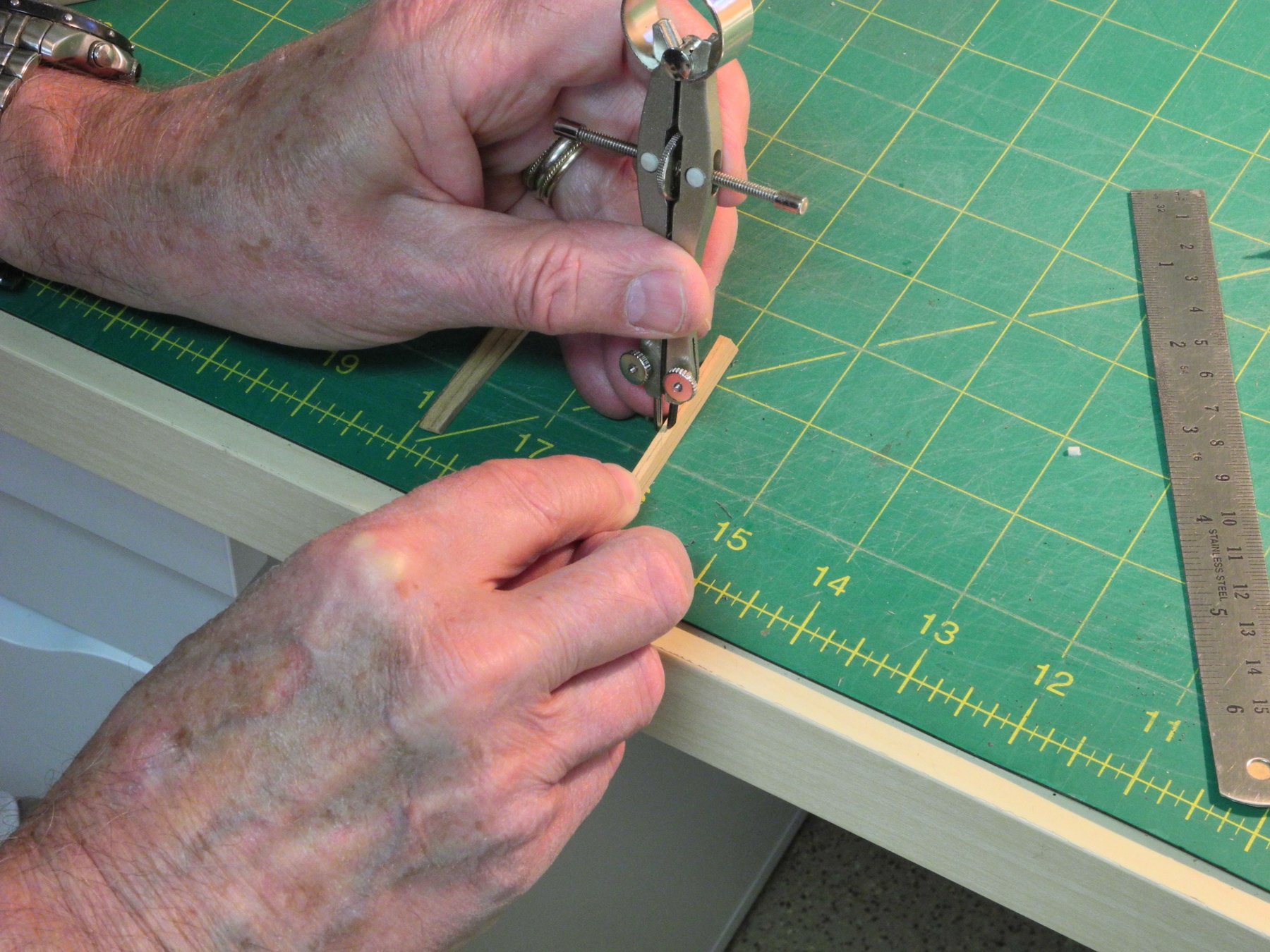
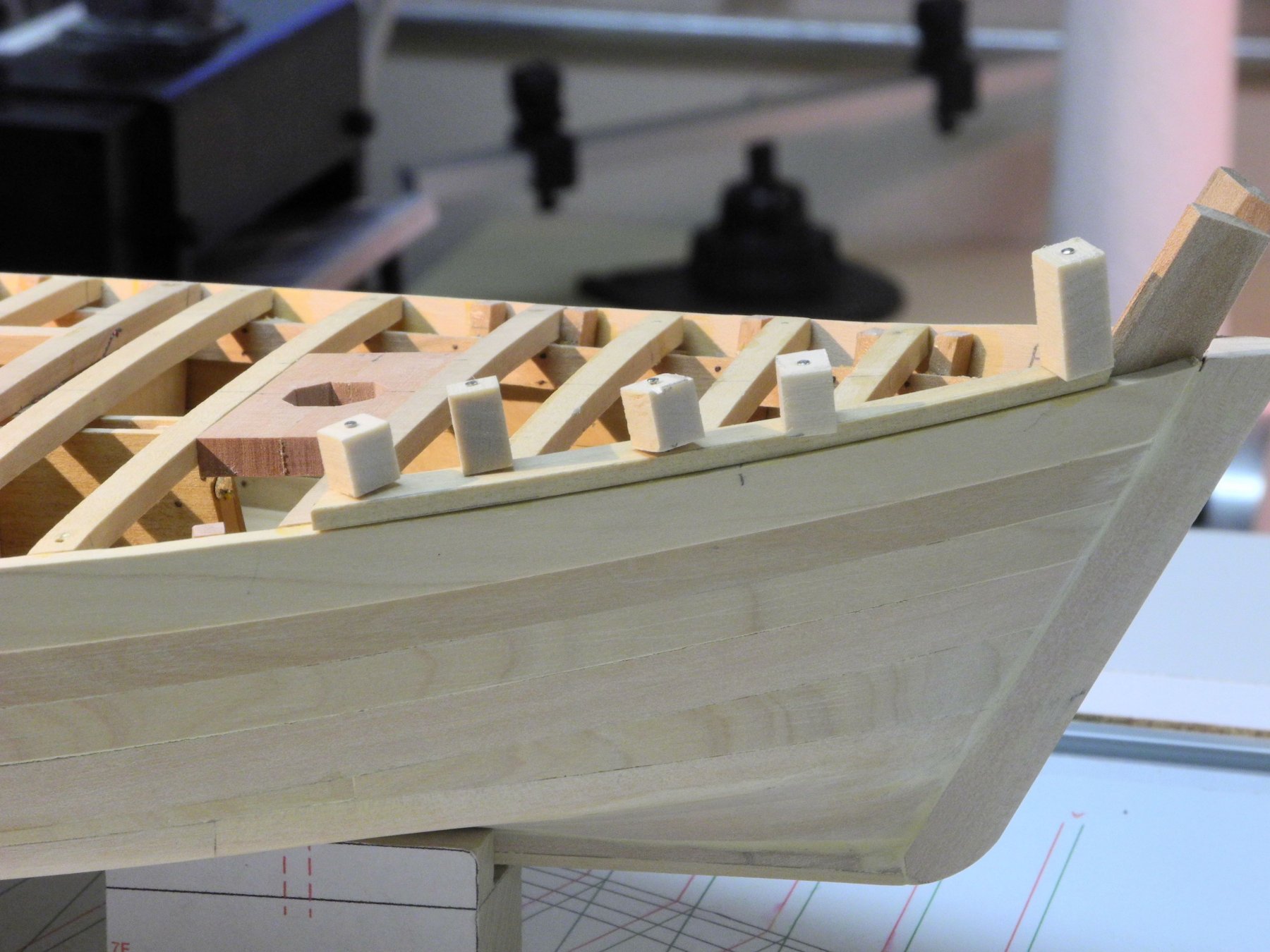
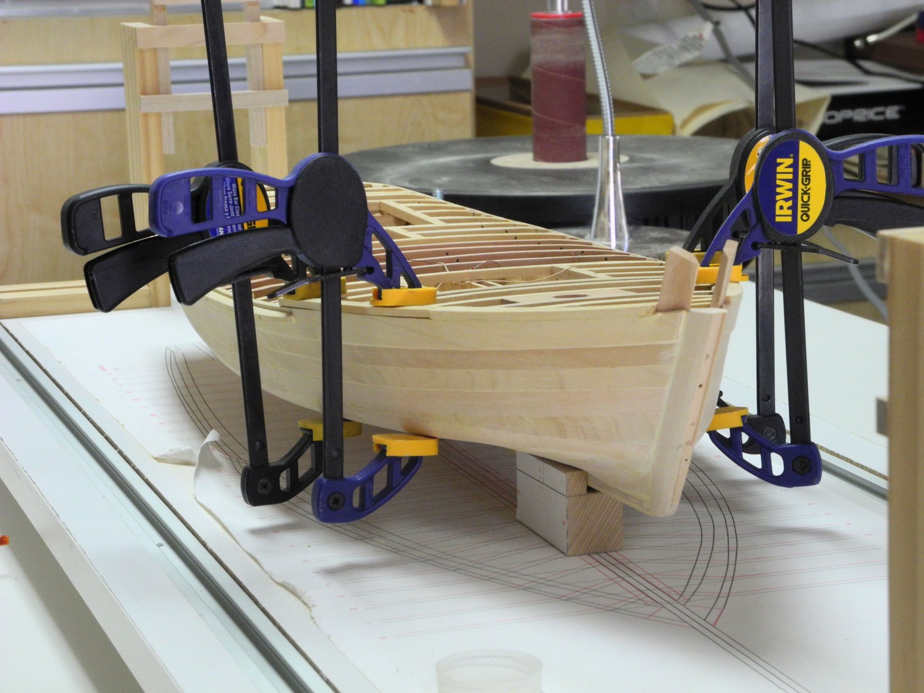
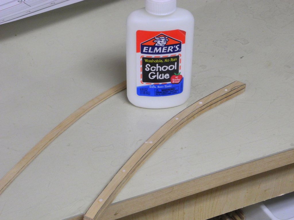
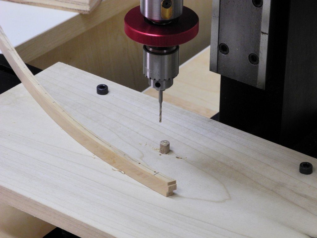
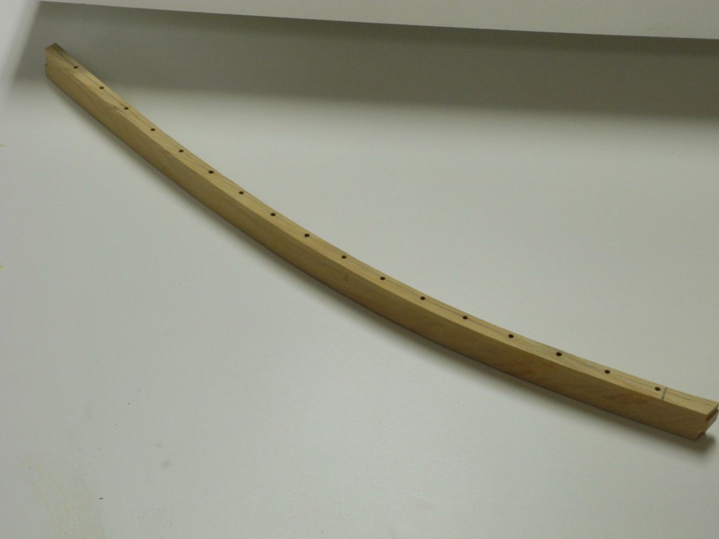
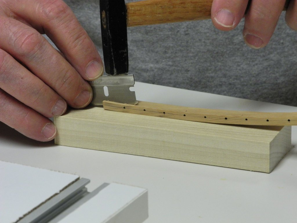
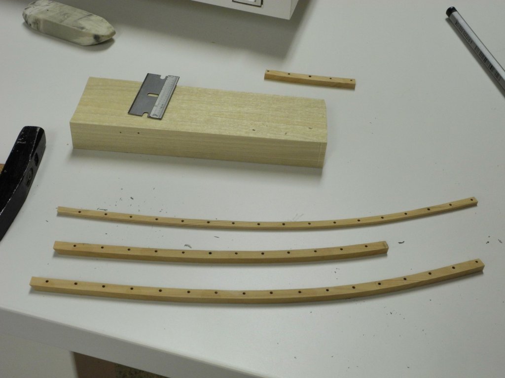
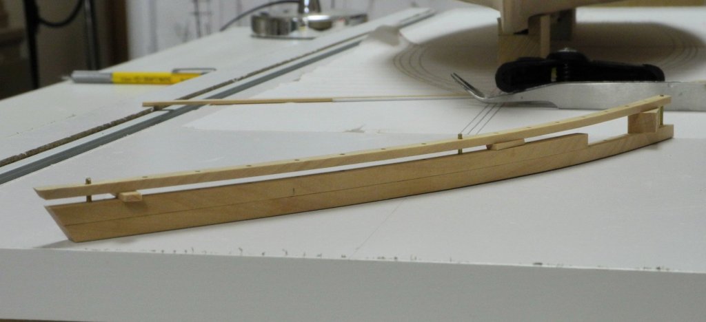
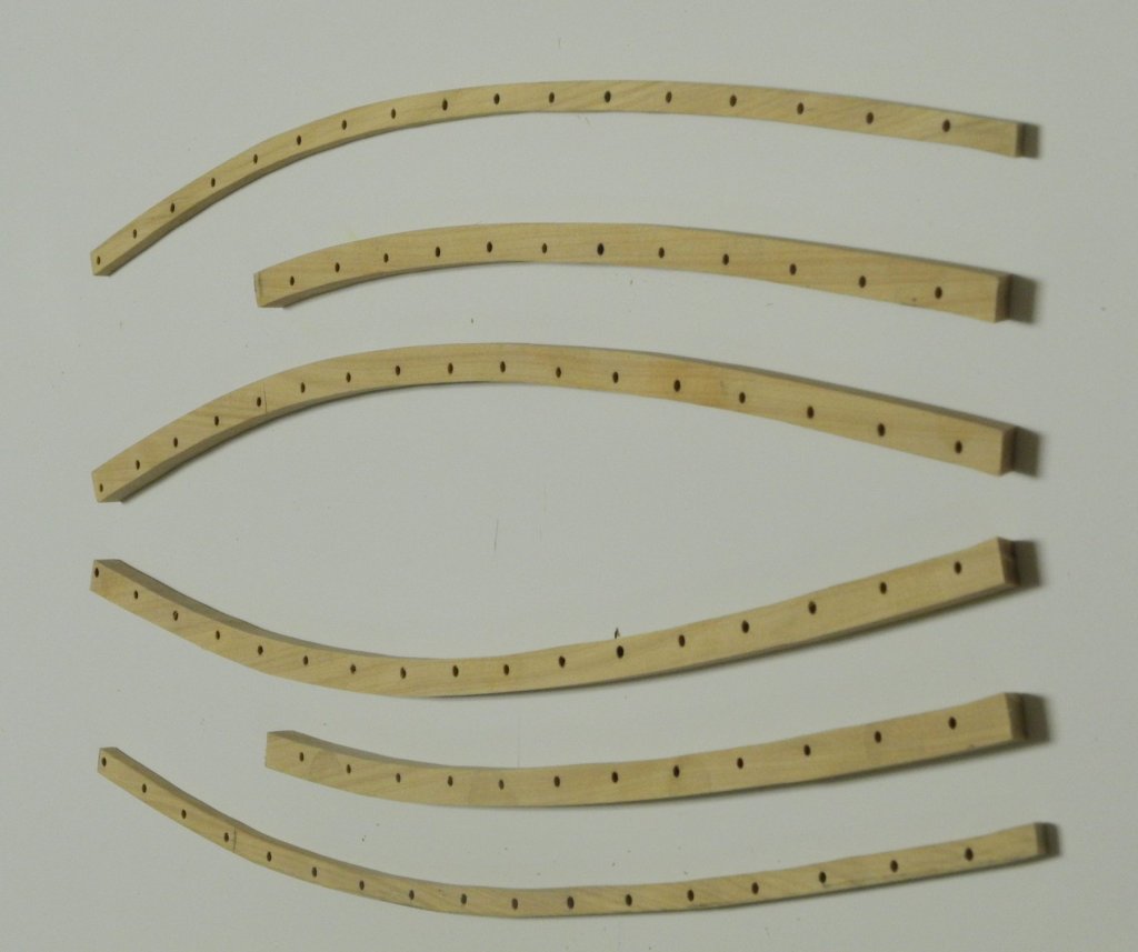
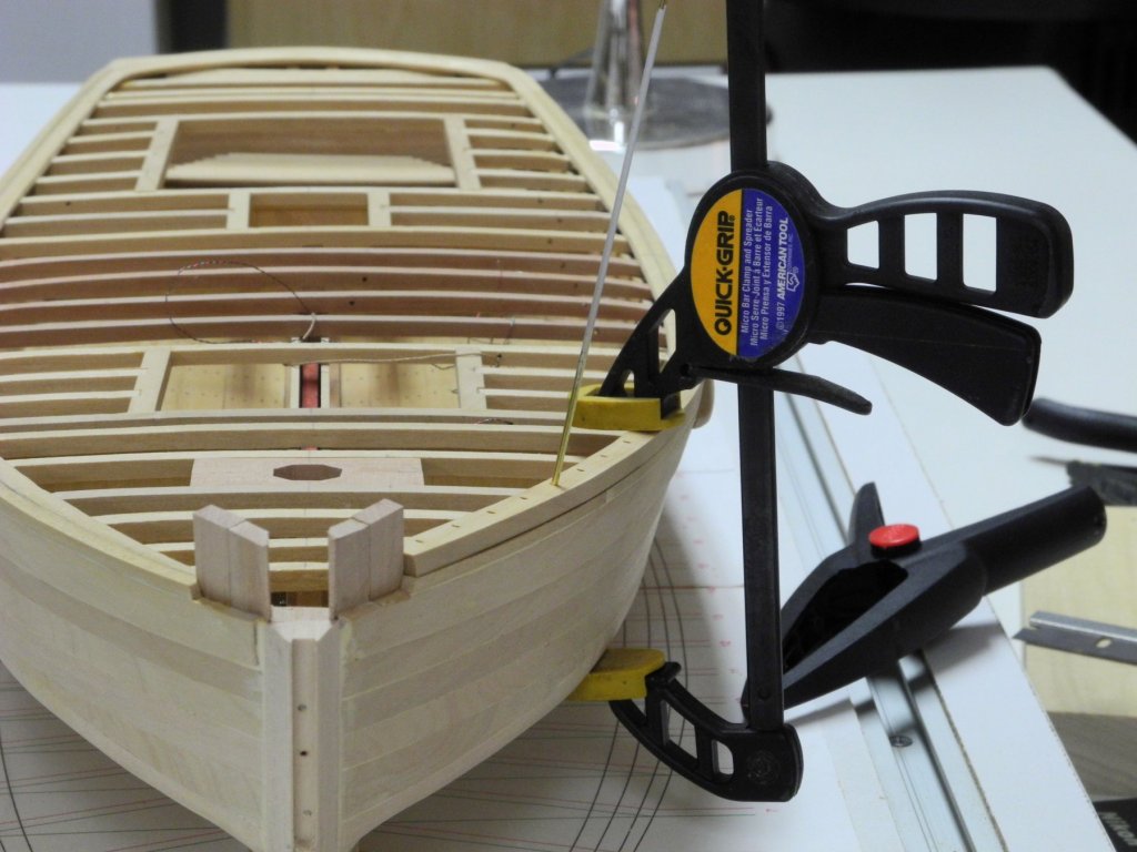
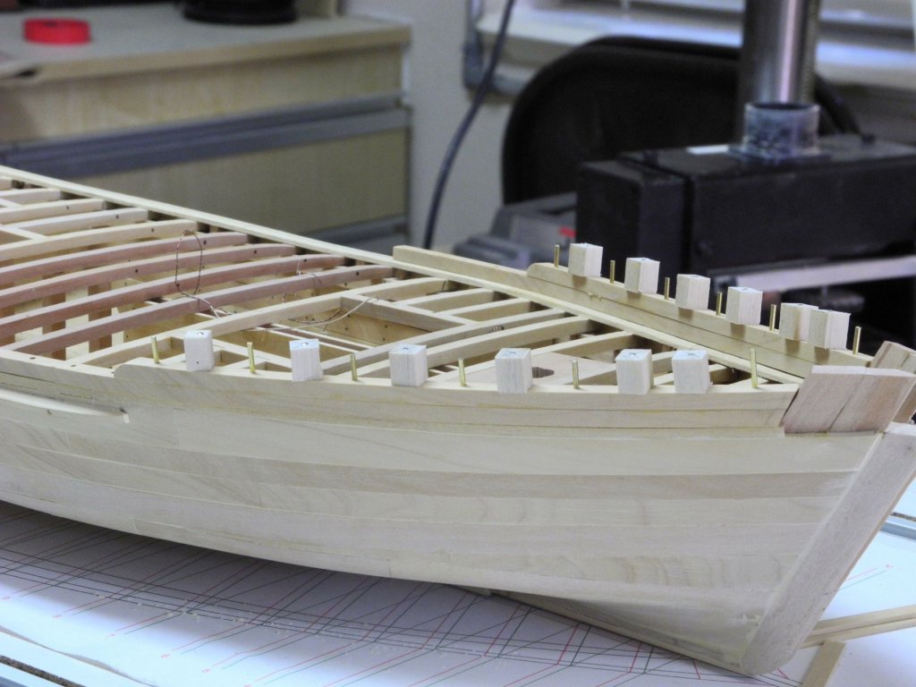
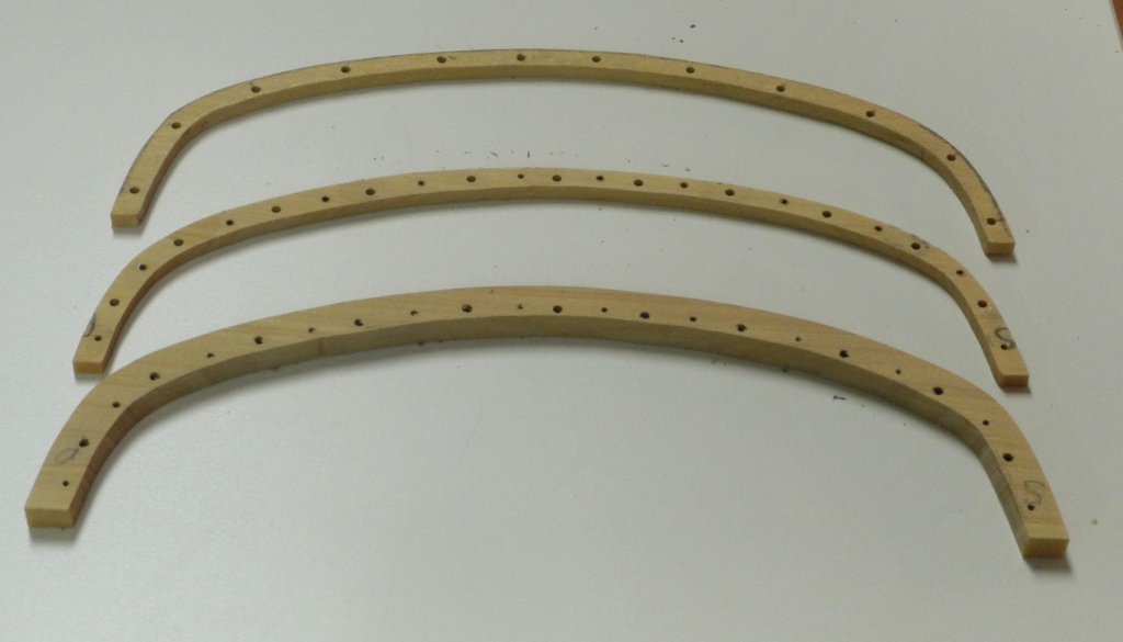
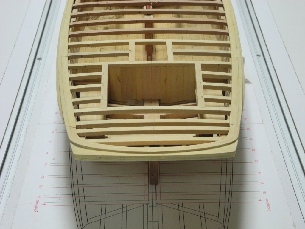
Part 29 – Log Rail Kathryn’s sides above the waterway consist of a log rail topped by head rails. The log rail is a 5” x 5” timber, the headrails are 4” x 3” supported by iron stanchions. This entire configuration is painted white. The forward log rails are doubled from a few feet forward of the dredge rollers to the knightheads, topped by a single head rail. The rails aft of the dredge rollers consist of the log rail topped by two head rails. The stanchions between these two aft head rails alternate in thickness, while the stanchions in the forward rails are a consistent thickness. This configuration can be seen in the following photos. The different timbers of the rails would need to be shaped to match each other and drilled for stanchions so that the holes would align. Using the plywood template developed in an earlier post, rough drawings of each of the components of a rail were cut on the scroll saw and were then glued together using small spots of school glue, as in the following photos. The line for the interior edge of the rail was an accurate depiction of that edge, and was used as the reference edge for the rest of the shaping. This edge was sanded to the reference line on the spindle sander. A compass was then used to mark the thickness of the log rail on the outer edge of this assembly. The assembly was then sanded to that outer edge line. While all components were still glued together they were drilled to accept the stanchions. A table with a vertical peg (used in one of the early posts when shaping the keelson) was set so that the holes would be drilled a consistent distance from the inner edge. After drilling was completed, the cap rail was separated from the assembly be gently tapping a razor blade through the glue joints. Since the width of the cap rail is less than the width of the log rail, the width of the cap rail was marked using a compass, and the rail was then reduced to its final width using the disk sander. The two pieces of the log rail were separated, and the upper rail was reduced in length. The fit of the three pieces was tested, using filler blocks for the spacing. The starboard side rails were then prepared. The log rail needs to sit level on the waterway so that the stanchions would be vertical. To test this, the log rail was clamped to the hull and a brass rod was inserted in one of the holes. The rod did not sit level, so the waterway was shaped using a rotary tool until it allowed the stanchions to sit vertically. The lower log rail was pinned and glued to the hull, and then the second log rail was pinned and glued, using some brass rods to assure proper alignment. After gluing the log rails the forward cap rails were temporarily installed. Since this seemed to achieve a good result, work continued on the remainder of the log rails. The next section ran from the end of the first section to the round section in the stern, and consisted of the log rail and two cap rails. The complex arrangement of the stanchion holes can be seen in the following photo. The log rail was pinned and glued. The log rail and the two cap rails for the rounded stern were prepared in the same way. The log rail is now fully installed. The cap rails will be left for a much later time. I’m afraid that installing them too soon would make some of the remaining work (deck planking, etc) more difficult and would present a risk to the cap rails. The following photos show Kathryn’s current state. Sorry for the very long post, but it was a fairly complex subject for me. Thinking about how to install the log rails has been my sole focus for the past few days, so I’m not sure what task will be next. There are several items that are independent of each other, and I don’t think the sequence matters too much, so we’ll see what develops! Thanks everyone for following this build – it has been a real education for me, and a very enjoyable experience so far.


- 878 replies
-
- 21
-
-
Hi Popeye. I agree on leaving a little extra - even though in this case it was not intended it did work out well. The knightheads weren't too difficult, since there was lots of room where they should have been.
-
Thanks, Druxey. No, I didn't sweat very much about fixing the waterway - it actually was pretty simple. Maybe I'm just getting used to fixing my mistakes - I'm getting a lot of practice at it!
-
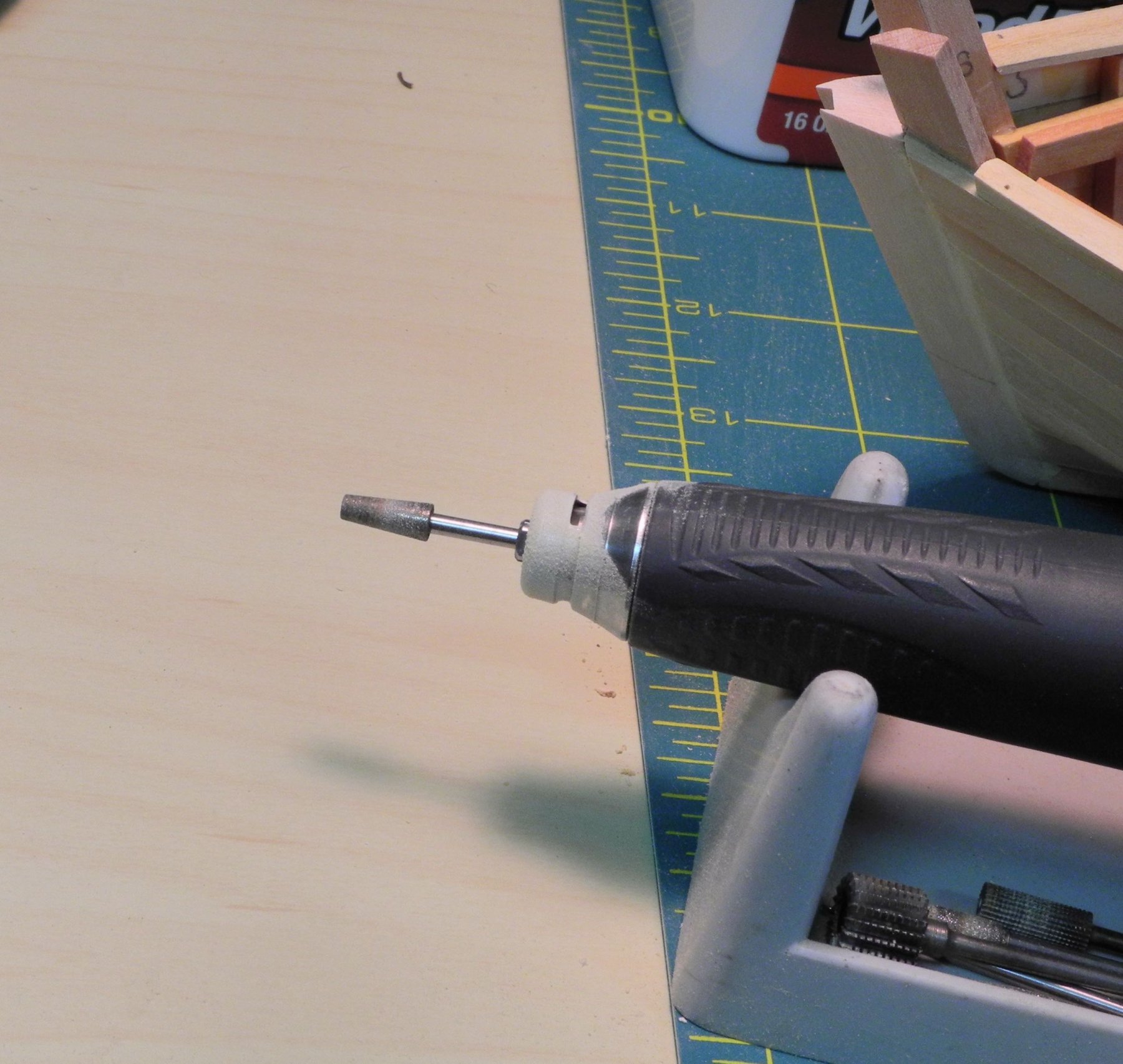
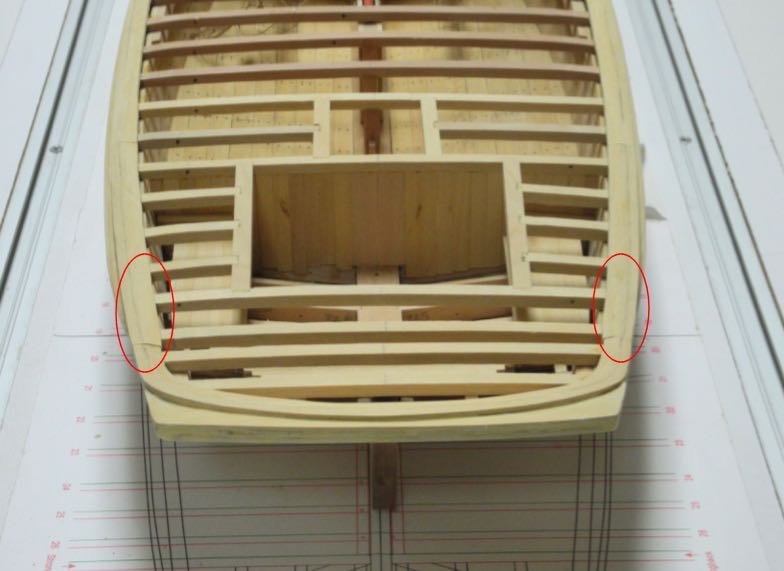
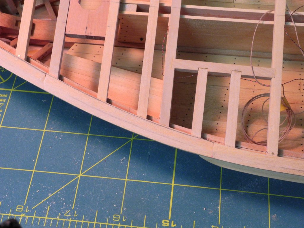
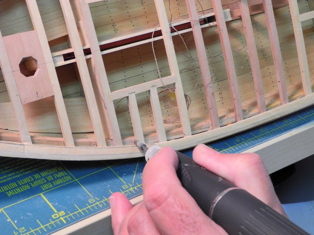
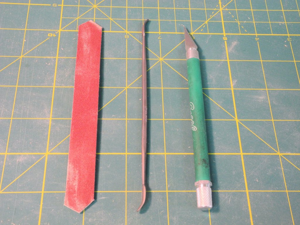
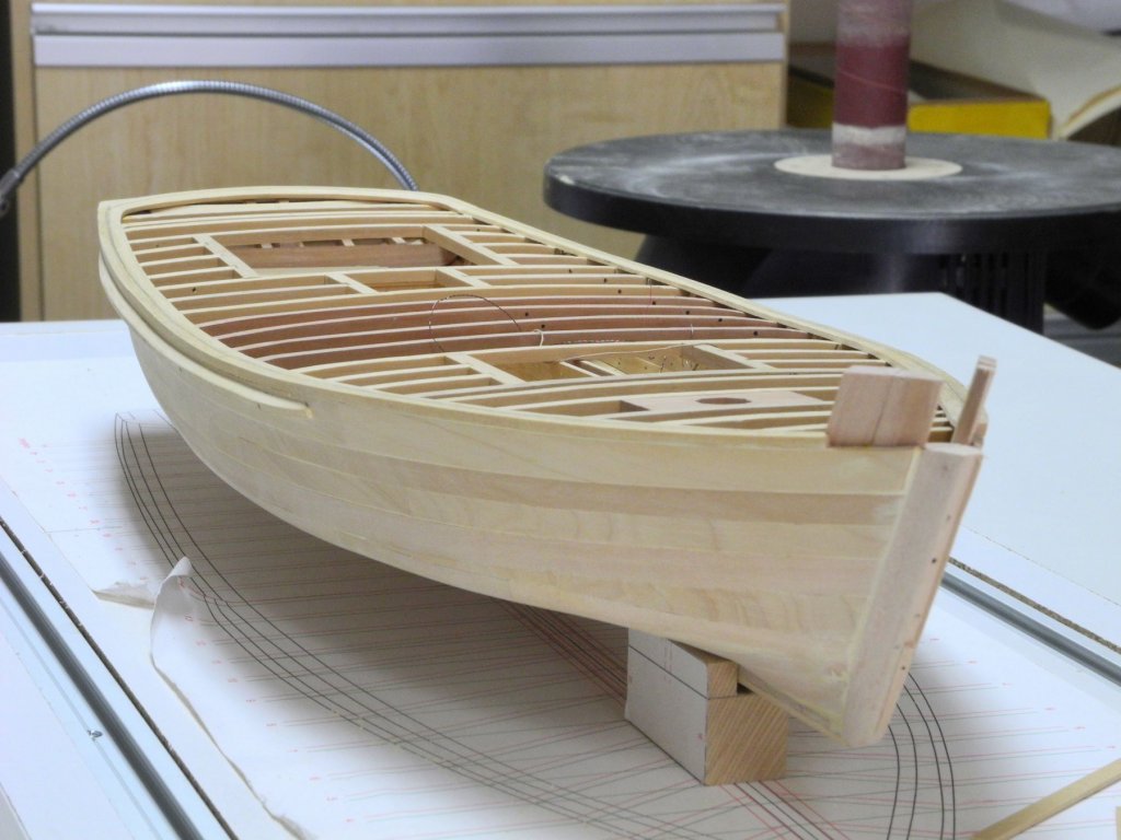
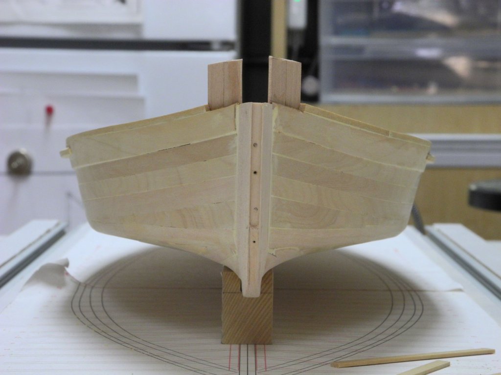
Part 28 – Some Fixes Looking at the photos in the last post I noticed that the waterway width is not consistent – this needed to be corrected, since it would cause problems when the deck planks are installed. The circled areas in the following photo illustrates the issue. This was the most obvious area that was out of measurement, but wasn’t the only one. A compass was set to the proper measurement for the waterway width, and was run around the entire waterway to determine where corrections were needed. Fortunately there were no areas where the waterway width was too narrow. The problem areas were reduced by first using a diamond bit on the rotary tool to remove the excess stock. This tool is a tapered round grinder bit, and has a ‘safe end’ that allows the tool to run against the deck beams without taking any cuts in those beams. After removing most of the width, a variety of tools were then used. From left to right in the following photo: a sanding stick made from a tongue depressor, with angles cut into the ends to allow close sanding work; a riffler file with a safe edge – allowed working against the edge of the waterway without damaging the waterway; and a hobby knife to clean up the final work. The waterway is now a lot cleaner and more consistent, as in the following photo. I also noticed that I had made an error when installing the knightheads. The measurements I used were for a single timber for each knighthead. Unfortunately the knightheads are made up of two timbers on each side. This was an easy fix, since there was still enough room to add the second knighthead timber on each side, and only required cutting away the forward part of the waterway. If this hadn’t been discovered before the subsequent steps, correction would have been much more difficult. The following photos show Kathryn after these corrections were completed. Next up is the installation of the Log Rail.


- 878 replies
-
- 20
-
-
Beautiful work, Ed. The level of detail is outstanding.
- 3,618 replies
-
- 4
-
-
- young america
- clipper
- (and 1 more)
-
Recommendations For A Good Milling Machine
Mahuna replied to Thistle17's topic in Modeling tools and Workshop Equipment
I bought my mill and lathe as used equipment on Craigslist. I live close enough to the Sherline factory that I've brought the machines to them for inspection and for them to make some adjustments. They provide great customer service. If you wind up buying a used machine and need some work you're not prepared to do yourself Sherline will always help you if you send the machine to them. -
Thanks Russ. I'm looking forward to getting the log rail on - then we'll see Kathryn's full lines. Thanks Patrick. Sounds like a fun idea, but I don't think I'll risk that! Thanks Ed. I sometimes have to remind myself to take photos of the process, but I've found that the 'current state' photos help me find some areas that need tuning. In a couple of the above photos I see issues that I missed and will need to clean up. As for the clamps, I guess you just can't have enough!
-
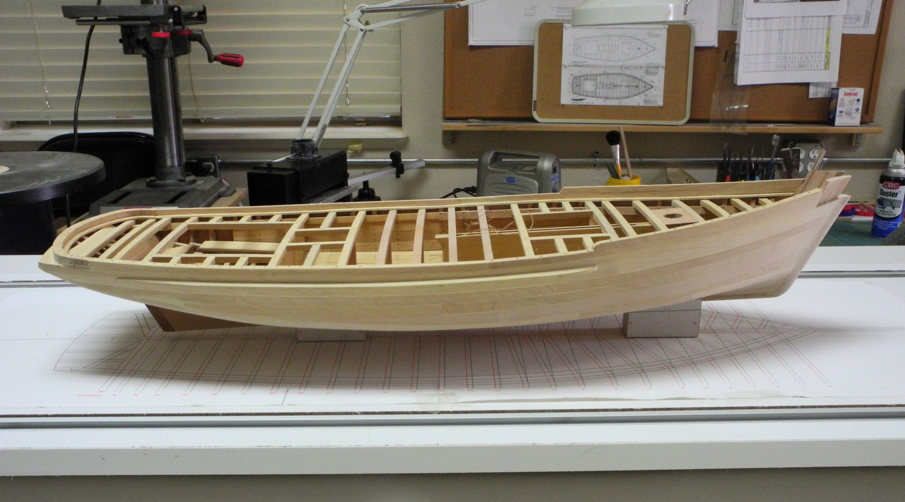
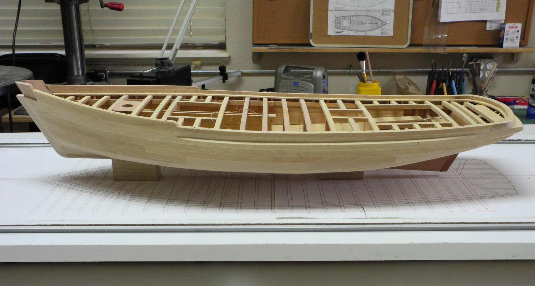
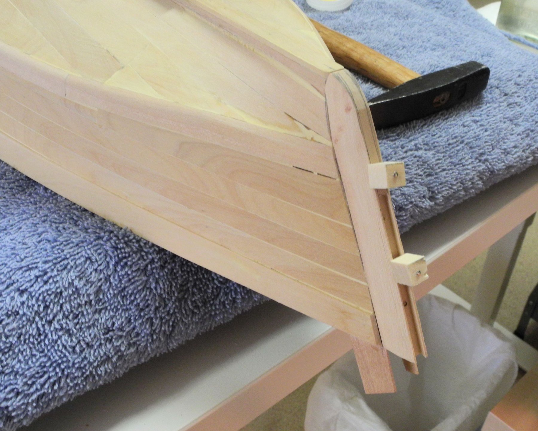
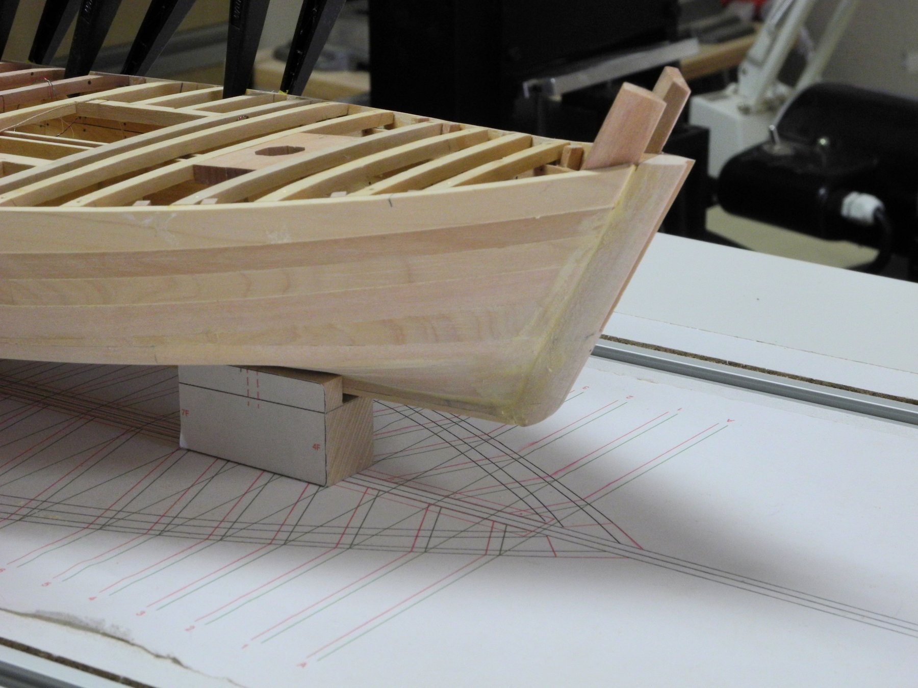
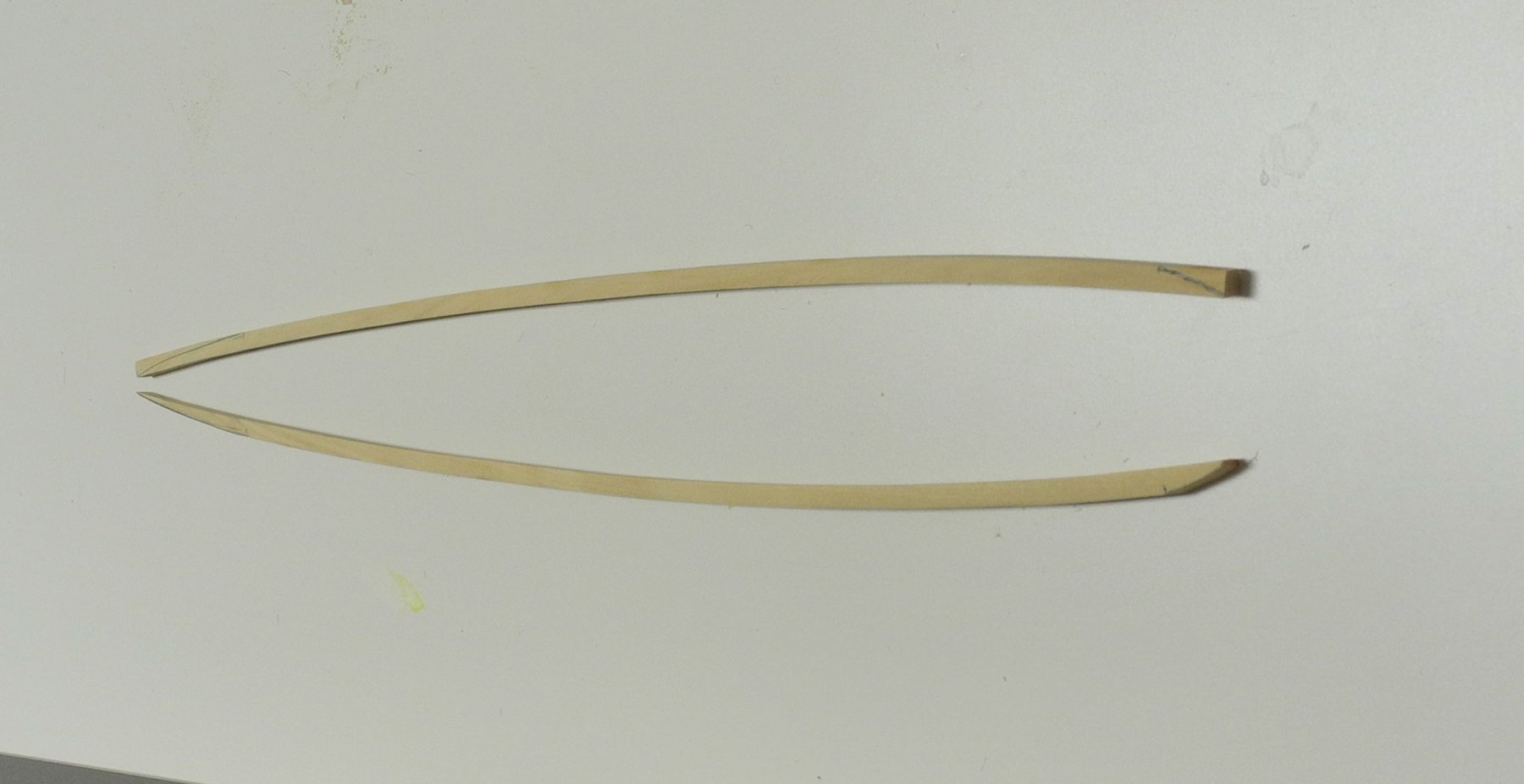
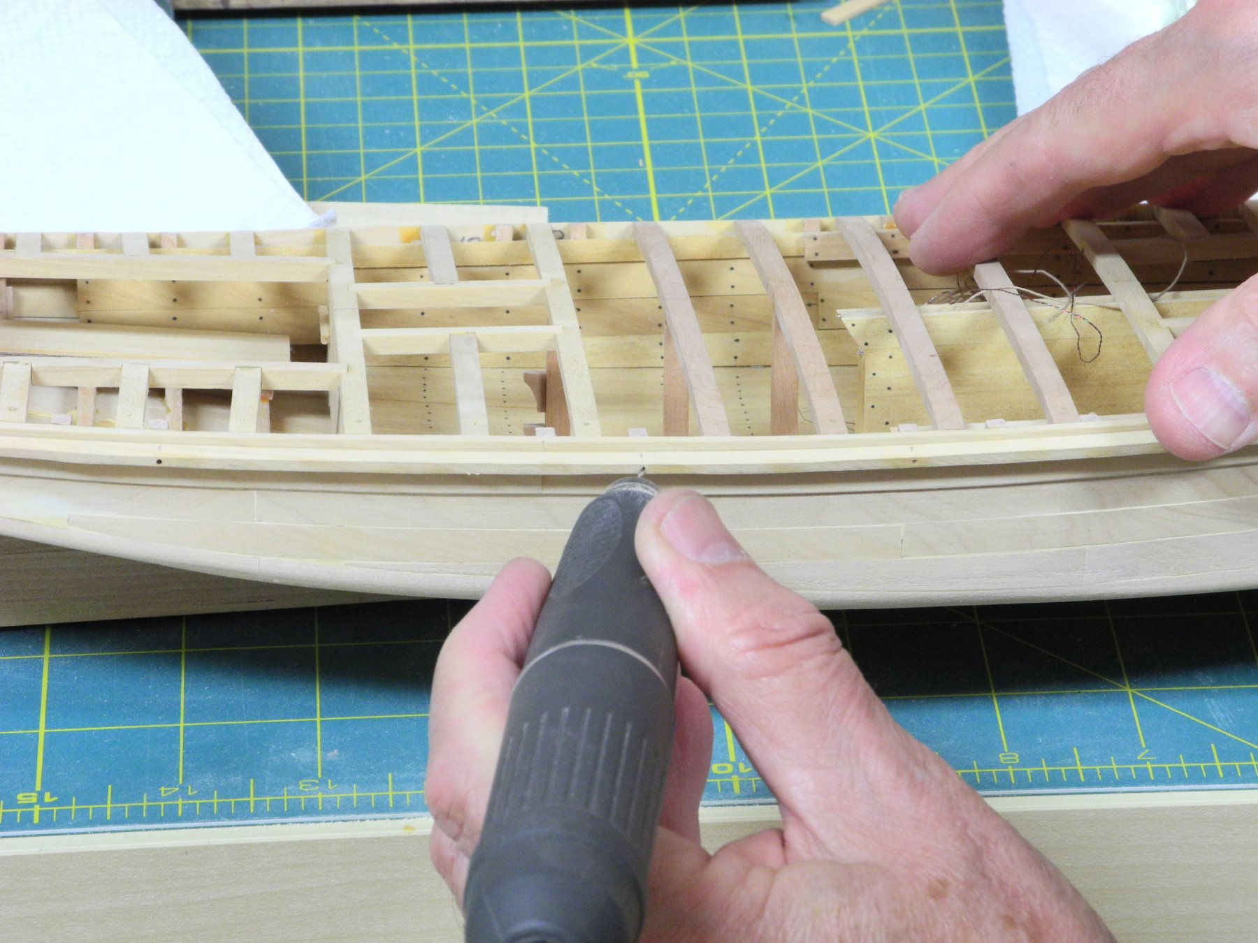
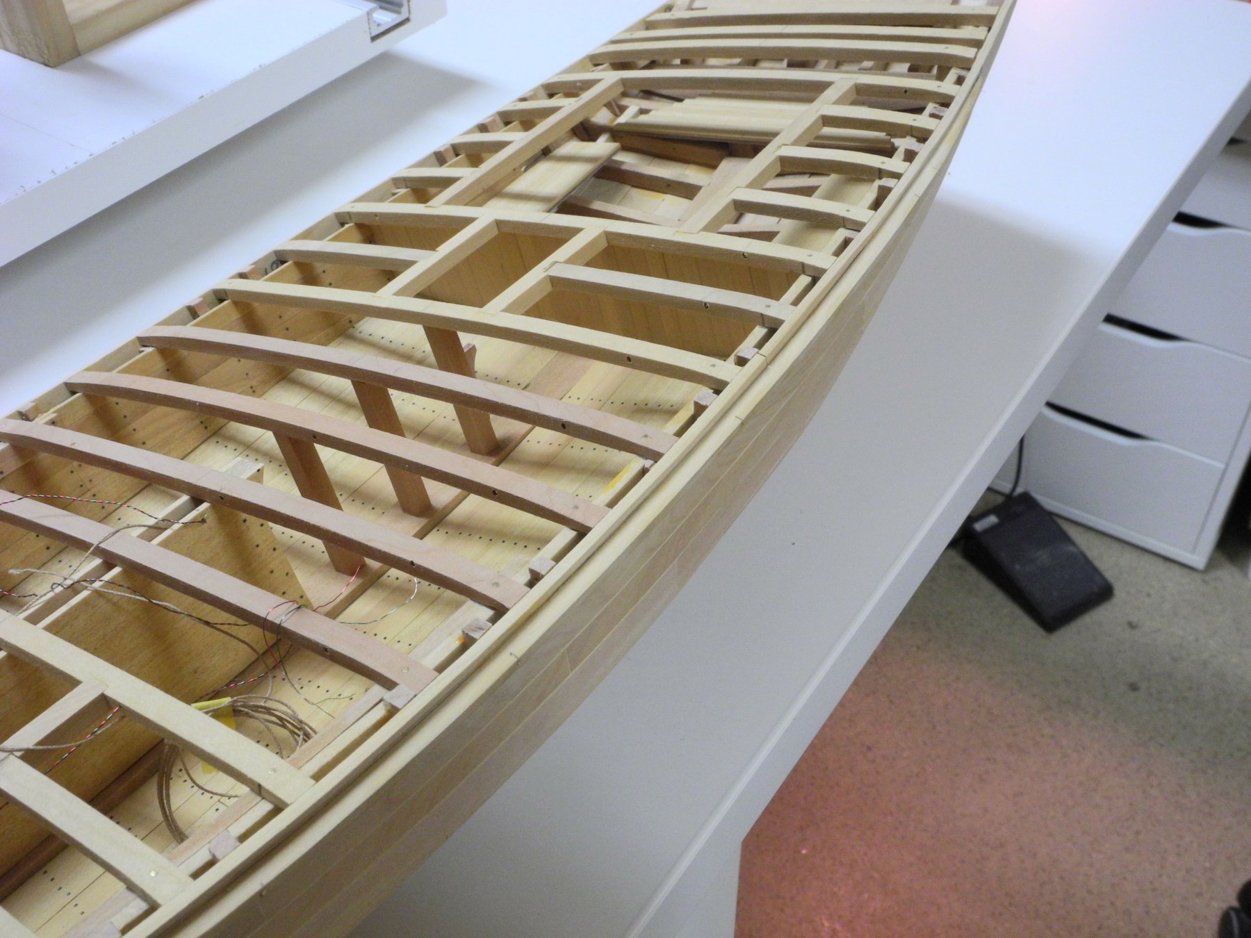
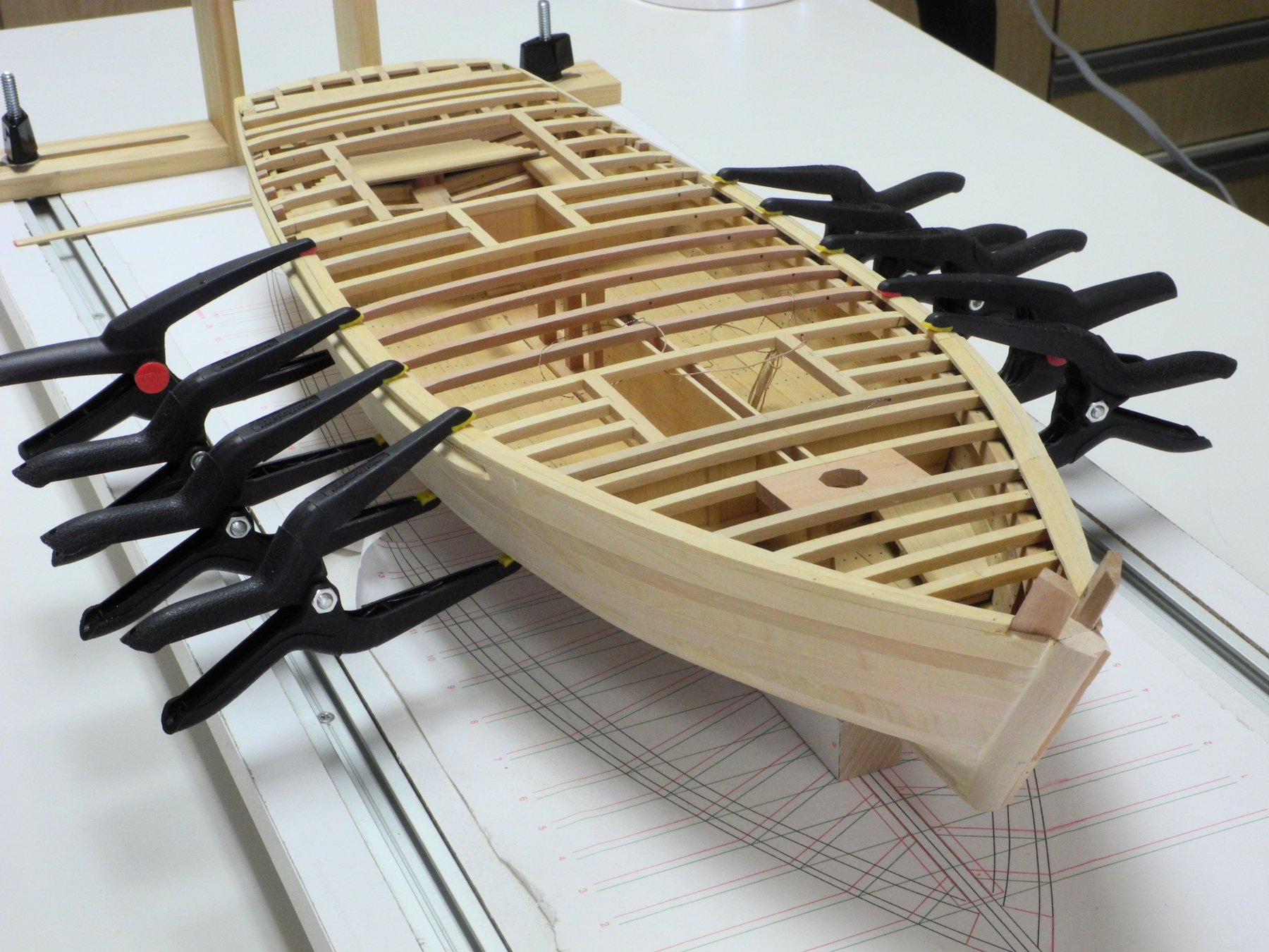
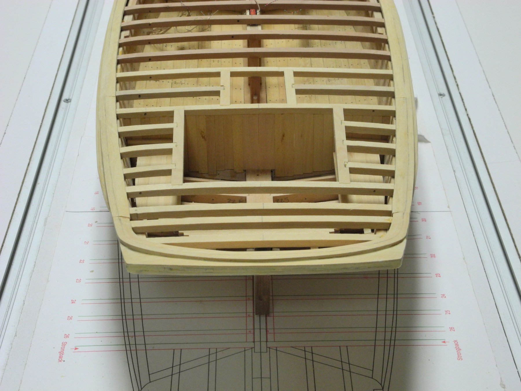
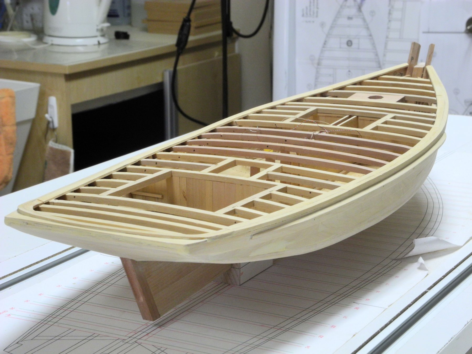
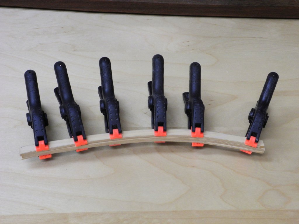
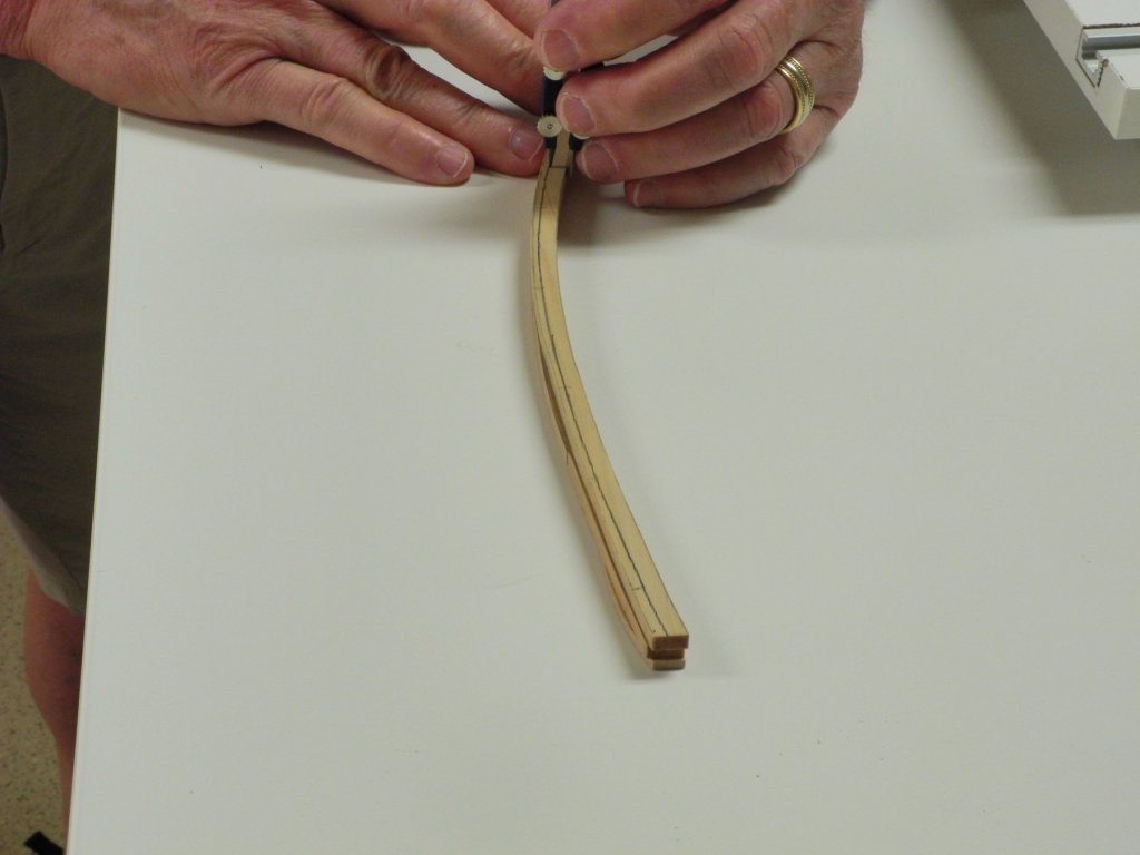
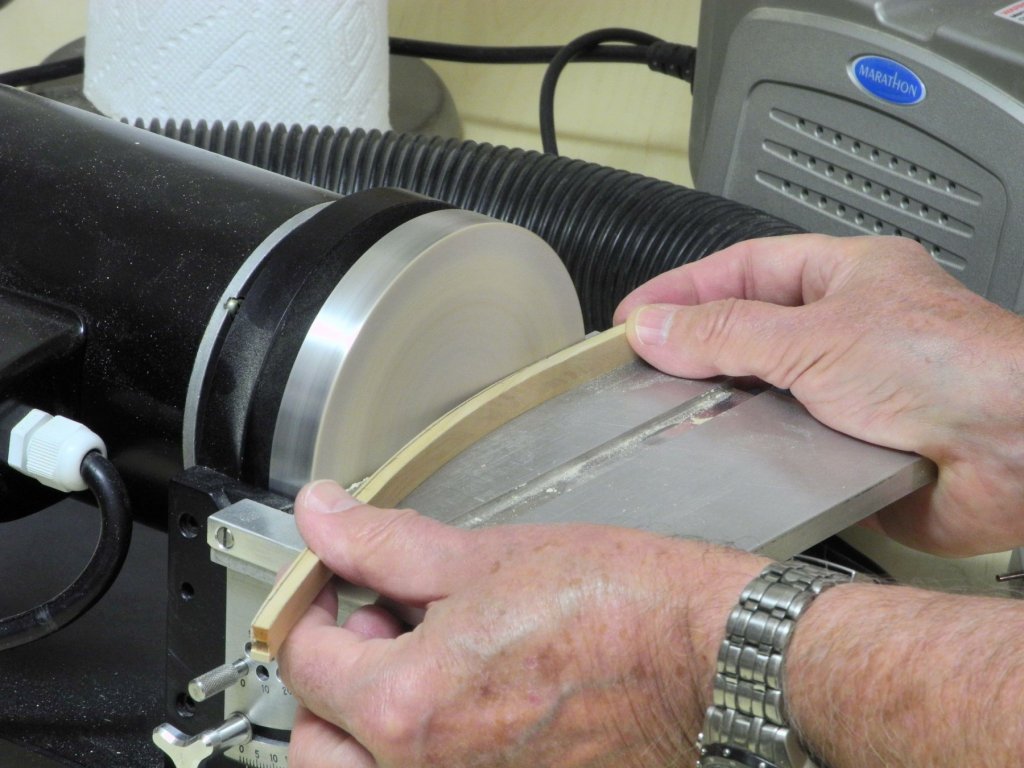
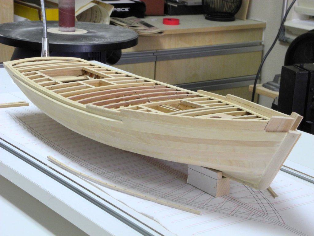
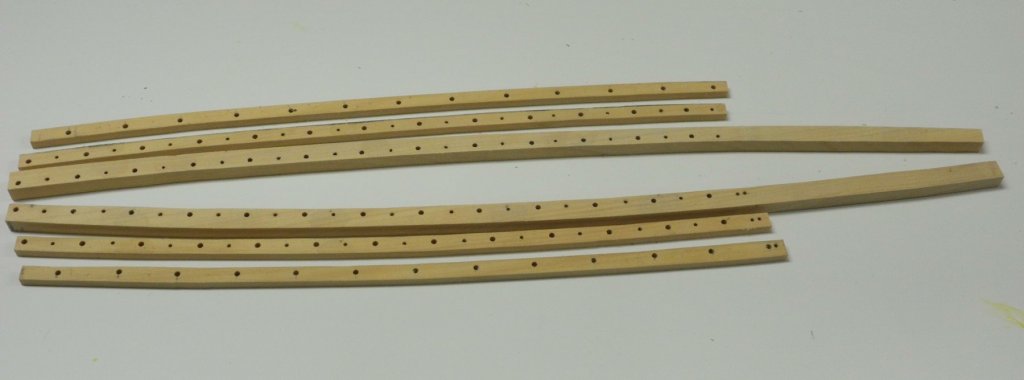
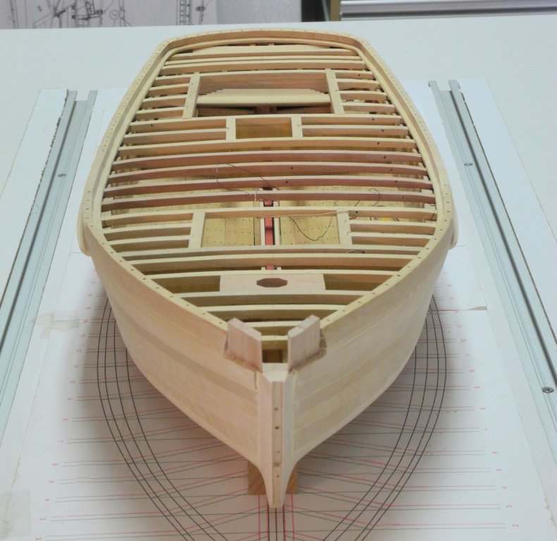
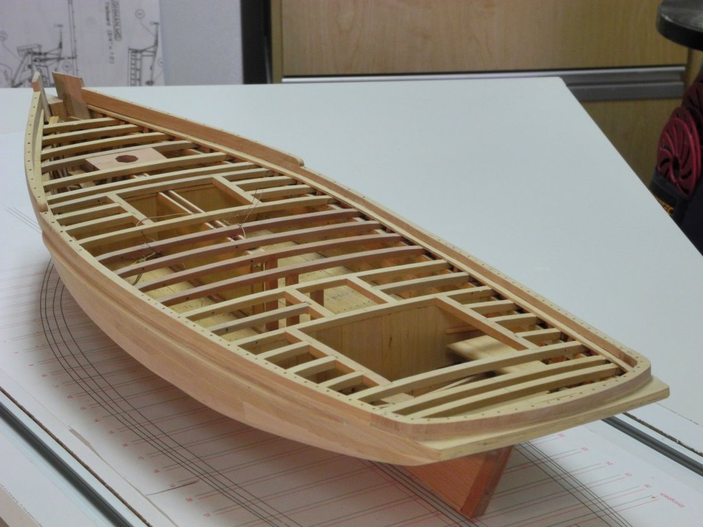
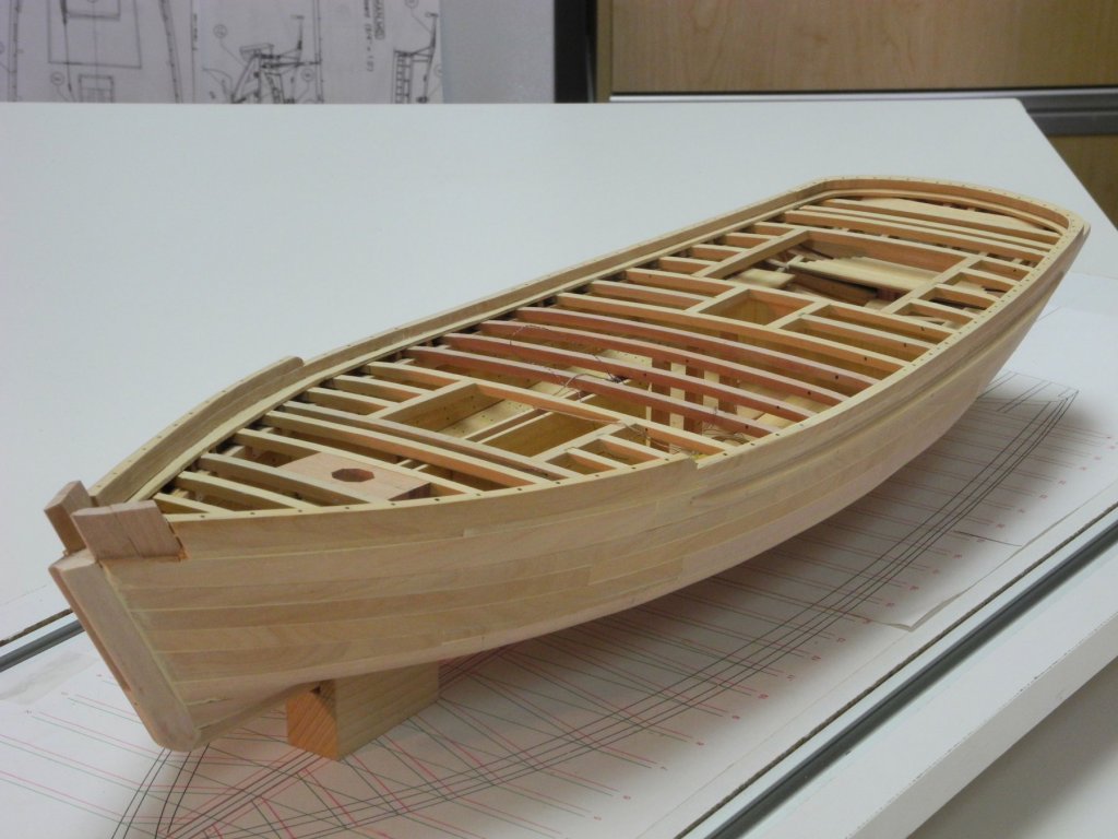
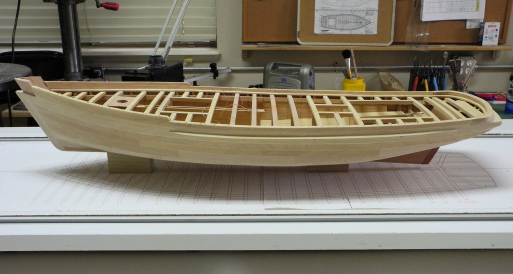
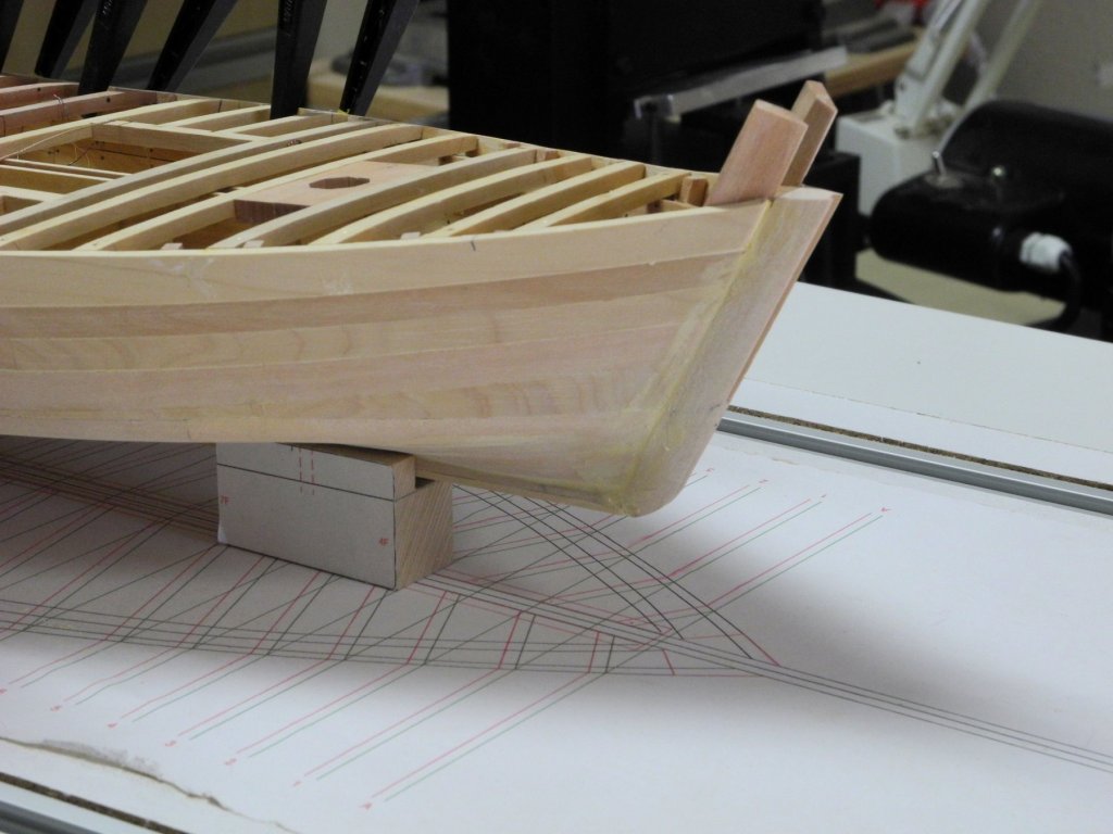
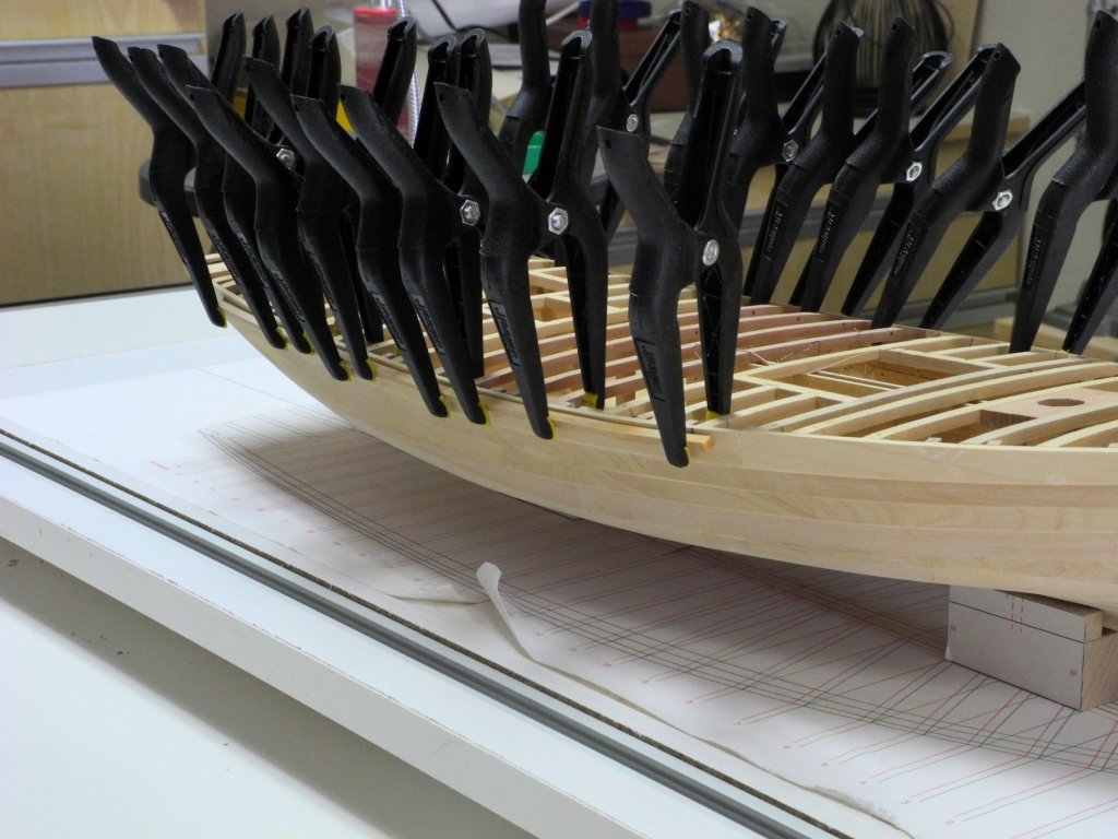
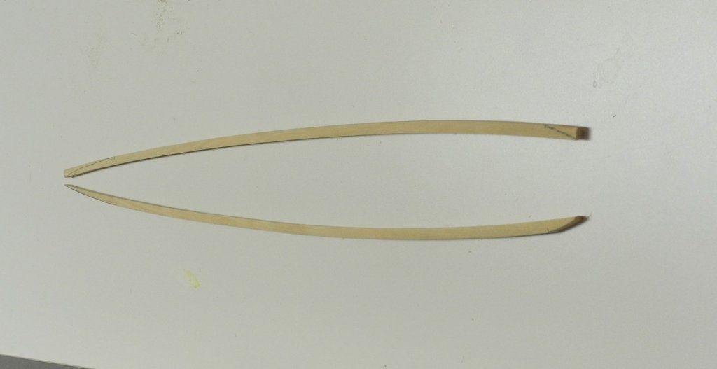
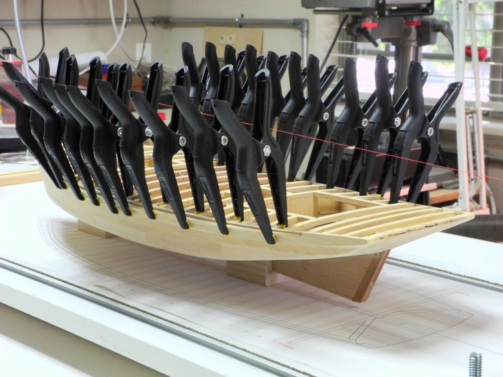
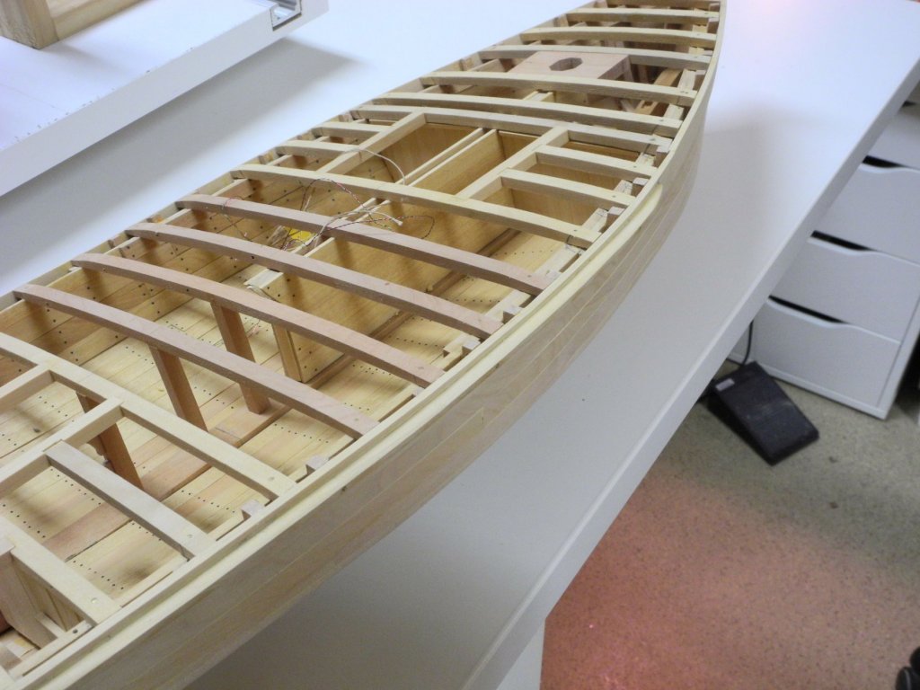
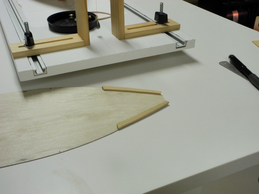
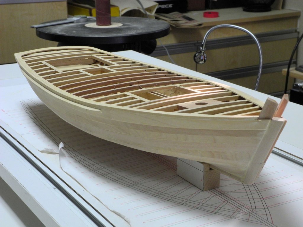
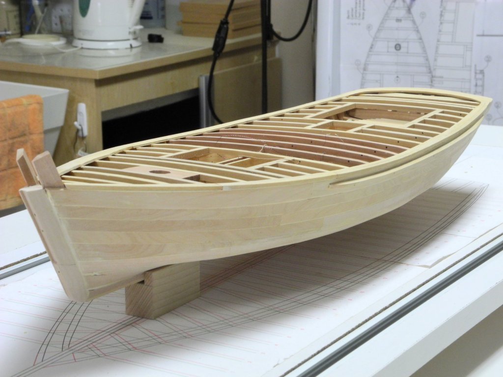
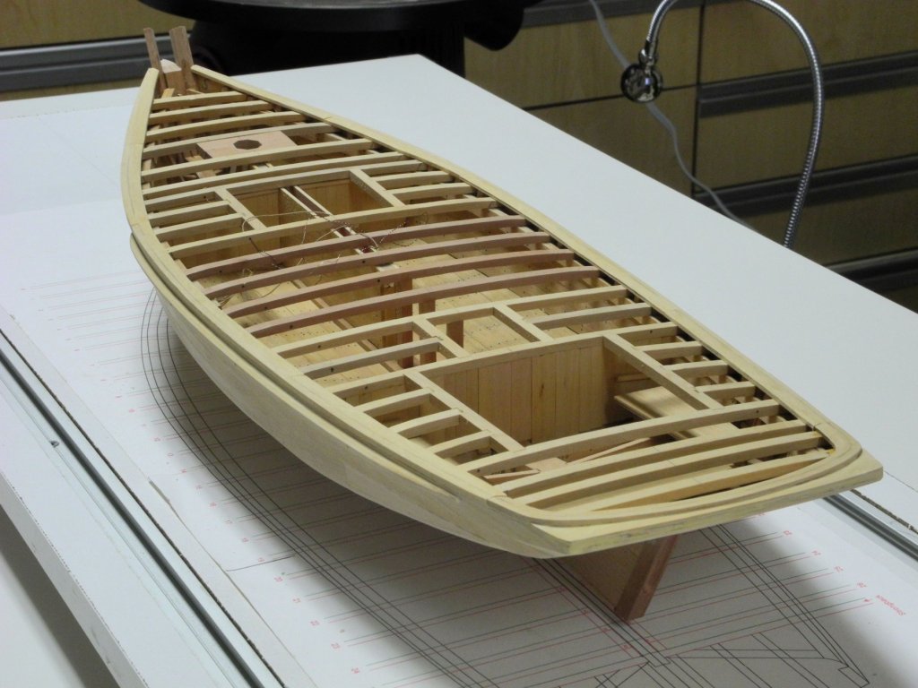
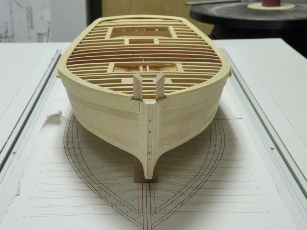
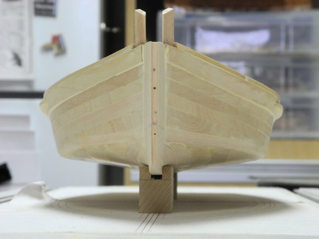
Part 27 – Guards and Waterway Having returned from our road trip to Colorado and Nebraska, it’s back to work on Kathryn. The first task is to install the outer stem. As shown in an earlier post, this timber has pegs inserted that allow it to be positioned against the inner stem, seating these pegs in holes that had been pre-drilled. The outer stem tapers from the edge of the hull planks to the cutwater, and rough shaping was done before attaching the stem. Since clamps would not hold on the slanted surfaces, temporary pins were used to hold the timber in place. The small wood blocks prevent damage to the stem when the pins are hammered in place. The shaping of the outer stem will be worked on as the rest of the hull preparation proceeds. Final shaping will wait until the Cutwater is installed. Kathryn, as in most other Skipjacks, has guards installed on the hull. These guards reach from approximately the forward hatch to just aft of the cabin. The guards are tapered – on the model the guards are 1/8” thick against the hull, and taper to 3/32” on the outer edge. The stock for the guards was tapered by hand prior to installation, and then the guards were soaked in boiling water and clamped to the hull for drying. The guards taper in the forward and aft ends. The following photo shows the starboard guard (bottom of the photo) already tapered, and the port guard awaiting tapering. After drying for 8 hours, followed by the fore and aft tapering, the guards were glued to the hull. Holes for functional bolts (1/32” brass rod) were pre-drilled before the guards were glued in place. Once the guards were in place, the hull was drilled to accept the bolts, and then the bolts were glued in place using medium viscosity CA. The following photos show the aft taper of the port guard and the forward taper of the starboard guard. The next task was to make the waterway, which is the lower part of the log rail. A template was made from 1/32” plywood in order to facilitate measuring and shaping of these components. The forward section of the waterway, from the knightheads to the area of the mast, are tapered. The width of the waterway at the knightheads is 7”, and this increases to 10” at the mast. The 10” width is then continued for the rest of the waterway. The following photo shows the forward section of the waterway after initial shaping. The waterway is flat in the area of the log rail – the outside 4 inches – and is 4 inches thick in that area. It then tapers to deck plank thickness (1-3/4”) on the interior edge. A compass was used to mark the outside edge for the log rail. And then was used to mark the plank thickness. The water way was shaped using a rotary tool and sanding blocks. The forward section of waterway needed to be pinned in place, since clamps would not work. The rest of the waterway sections could be held in place using clamps. Since the model will be painted I did not use scarf joints to join the sections. The aft section of the waterway and log rail do not extend all the way to the transom – they are curved just forward of the transom. There is still a lot of cleanup (scraping and sanding) prior to painting, but the log rail and some other items need to be installed before the cleanup can be completed. The following photos show the current status of the model. Next up is completion of the log rail, which will be the subject of the next post.


- 878 replies
-
- 25
-
-
PVA is a type of glue - Elmers is a brand name for their version of PVA glue. Titebond is another brand name. All PVA glues sold as wood glue work well and can be unbounded using hot water or isopropyl alcohol.
- 1,135 replies
-
- 3
-
-
- model shipways
- syren
- (and 2 more)
-
Rich - on the way home (currently in Albuquerque) and will be home tomorrow PM. We were in Colorado and Nebraska visiting family. Much cooler there!