realworkingsailor
-
Posts
3,273 -
Joined
-
Last visited
Content Type
Profiles
Forums
Gallery
Events
Everything posted by realworkingsailor
-
 This one: https://www.sunwardhobbies.ca/border-models-avro-lancaster-132-scale-with-full-interior-bf010/ ?? Have fun!
 -
Thanks! Sounds like you’re having fun with that modelling club! Yeah they’ll lead you down some rabbit holes, but it’s all fun. Airfix kits are generally pretty good, with some caveats. The more recent releases are cleaner, better, moulds, and require somewhat less fussing. If you see something interesting (regardless of manufacturer) you can check on Scalemates to see when the kit was tooled, preview the build instructions, and see what’s available in the way of aftermarket parts. Andy
-
Shipping is always the delicate dance. Is the value of the item(s) worth the shipping, or is the shipping cost extortionate. I didn’t do too badly on the aftermarket parts for my Wellington build (about $15 CAD) to bring that order up from Australia. However when I first went looking for decals for my Hurricane, it would have cost me $15 to ship a $10 envelope of decals from the UK (uh, that was a NOPE). For what it’s worth, have a look at Sunward hobbies, they have a $60 (CAD) threshold to qualify for free shipping for almost anywhere in Canada or the US. (Not associated with Sunward, just plugging a local business 😜) Andy
-
Not much to update on either the build or my busted collarbone. I’ve been bumped three times already due to “emergency” cases. The routine for the last few days has been wake up, get a phone call saying hang on for another phone call, starve for a longer part of the day than is comfortable, get a disappointing phone call, then gorge ravenously on whatever food happens to be lying about. Thankfully I’m at home and relatively comfortable, rather than mouldering in some hospital, going squirrely. On the positive side, my decals arrived today! Very nice! Might have to buy a couple more hurricane kits, can’t let a good decal sheet go to waste! The decals are printed by Microscale, so the paper and film should be of good quality, and the print alignment looks great (no off centre roundels). The only thing that’s missing is the registration number for the Hurricane I wish to do, but that’s ok, since the number is black I can experiment with my word processor, laser printer and some blank decal paper. I’ve done that trick before and it works pretty well. For what it’s worth, I don’t have too many concerns ordering again from Thunderbird Models. For my fellow Canadian modellers, there are some interesting domestic aftermarket decal options for commercially available kits, as well as a plethora of details for anyone interested in bush planes and pioneering in the far north. They also carry a rather extensive line of instrument panels details for a wide variety of aircraft. Their website is worth exploring, there might be something there that you’re look for. Andy
- 92 replies
-
- 10
-

-
Duct tape! 😆
-
Thanks guys, I will absolutely be sure to follow instructions. Just heard from the hospital, my surgery is confirmed for Sunday. I’m mostly pain free, and only need the occasional over-the-counter ibuprofen, so I don’t mind. There’s a plan in place, just have to go at things one step at a time. Andy
-
Thanks again, everyone! Small update. Just got back from the fracture clinic. Surgery is in my near future, pins and plates, maybe tomorrow. I actually feel this is a good thing, my recovery should be quicker and overall less painful, and in long term better for me. I’ll be back at the workbench soon! 🤞 Andy
- 92 replies
-
- 10
-
-
Pretty much all the advice/guidance/information given around here is shared with the absolute best of intentions. It is most welcome. Andy
-
Funny thing about that, the Airfix kit claims to include both options, but I can’t tell which is which. Probably the detail at 1:72 is too small to tell, maybe the plastic is a fraction thinner. They had to do something to keep the squeaky ones happy. Placebo effect! Andy
-
Thanks everyone for all your kind comments and well wishes! They’ve made a great start to my recovery. Thank you all so very much! Now that I seem to be blessed with extra googling time, I’ve made a rather interesting discovery with respect to my Hurricane build. Early on there was a discussion about my choice in colour scheme and whether it was appropriate for a fabric winged Hurricane. Well….maybe? 🤔 One of the options in the decal set I ordered was Hurricane V7203 LE T, part of 242 squadron (Douglas Bader’s bunch, he flew LE D). Digging a little bit I found this interesting discussion and photo on the Britmodeller forum. Seems like this particular plane, produced in July 1940, went into service with fabric, rather than metal wings. If you look closely at the photo in the discussion, you can clearly see the wing ribs, especially near the wingtip. Apparently (according to the discussion) the first few (25) Hurricanes of the “V” serial numbers came off the line with this configuration. Fabric wings, sky underbelly, and underwing roundels. So all you purists can climb back up the tree and don’t worry about the shaking… it’s just a chainsaw… 😜😁 Andy
-
I only wish I had the chance to get a picture of the trench I made. Or even better, had someone catch me on video. I really would have liked to see it unfold from an outside perspective. So many times we do these spectacular “stunts”, but like the “record sized” fish that got away, no picture, no proof! 😜 Andy
-
I broke my right arm as a teenager, in my case it was two wrists! Andy
-
Thanks Denis! (And for your other kind remarks as well!). No need to apologize, this build happened so quickly up to now, you’d be forgiven for not even seeing it at all. Probably a good thing my injury slowed it down to a stop, maybe allow people to catch up! Andy
-
Thanks, me too! Yeah, I kinda left myself open to that pun! 🤣 Must be the painkillers! 🤪 Andy
-
Soooo…. kind of a good news bad news update. First off, the bad news. I will start by allaying everyone’s fears, no models were harmed in the performance of this particular dumb human trick. I was out skiing yesterday, getting in some nice runs in, enjoying the sunshine and fresh air. The club was making the most of the cool weather to make snow. Shortly after lunch I was skiing down one of these particular runs where snowmaking was in progress (run was still open). To avoid getting hit full on with a blast of spray, I’d aimed for a spot close to the base of the snow gun, that looked clear. Well, as I was traversing this area, my skis abruptly stopped in the freshly blown crud, but made no prior mention of it to me, so I kept going. It felt like I was hurled into the “snow” onto my left shoulder. I plowed a pretty deep furrow in the hill (probably the only thing that stopped me digging any deeper was my head). The end result is I now have a broken collarbone. I have an appointment on Friday at the fracture clinic to see if I stay in the sling or get surgery to pin me back together. When my fall occurred I was in sight of the ski patrol station and they’d seen it happen. They also complimented me on the size of the crater I left in the hill. I was always told, if you’re going to do something, do it right, no half measures. 😁 On a lighter note, I also received a confirmation email yesterday that the decals I ordered have been shipped. So silver linings. Andy
- 92 replies
-
- 10
-

-

-
So I’ve ordered some replacement decals this morning. I decided to skip Airfix altogether and try something aftermarket. Thanks to @Egilman for the advice on what’s out there, I opted for an Xtradecal set. Initially I looked to order them directly from Hannants, but the price for shipping a $10 envelope of decals was over $15. I “noped” out of that option. A little bit of digging and I found the same set available from a company called Thunderbird Models. They’re a small operation somewhere up in Saskatchewan. They have some interesting products if you’re into bush planes and the like. Anyway, their shipping was a much more reasonable $2.50. Fingers crossed my order will be shipped soon and Canada Post will deliver. Andy PS: All prices above in Canadian dollars. 😁
- 92 replies
-
- 12
-
-
I tried that trick, it had vacuumed itself shut, and the film seemed too thin to risk trying to even gently tease it apart. I’ll see what Airfix has to say on Monday, and then I’ll go hunting for aftermarket replacements. The worst I ever experienced was a bad set from Black Cat Publishing. The film was so thin it just shattered. Andy
-
Well, things have just come to an unexpected pause…. Speed bump… pothole… something… I was starting on the lettering, following my usual (well proven) procedure for applying any kind of decal. I decided to start with the registration number, as the next fuselage side decals take their relative positions from the number. Just as I’m sliding the decal gently off the carrier sheet, into a dab of micro set, the whole decal balls up into a Gordian knot…. What happened next is not permitted to be printed here🤬. Looks like I’ll have to chase down Airfix for a replacement lettering set. Nuts…. Well, back to the bomber 🙄 Andy
-
Not necessarily, while that’s certainly the more common convention, the bar could also be placed aft. See the table on document page 3: https://msi.nga.mil/api/publications/download?key=16920950/SFH00000/HoMCA.pdf&type=view If you look at the far right top block concerning the Flinders bar, the adjustment and effect are given for both a forward, or an aft mounted bar. Remember this is also still the period of experimentation in the adjustment of compasses. Kelvin hadn’t even been born at this time (he’s the one responsible for the invention of the spheres seen beside more modern ship’s compasses), so I highly doubt that the position of the correction magnets or bars had been settled at this time. Andy
-
If you don’t mind me chiming in here (amazing build, BTW), I believe you are most likely correct that the device is some form of compass correction. Flinders wrote his paper on compasses and magnetism around 1805, so it’s quite possible that a Flinders bar, or some similar device was in regular use at the time of your Creole. There are many facets to the errors that can be found in a magnetic compass, not solely the iron present in the ship (of which, the ordinance is more than enough to induce an error). Other factors like drastic changes in latitude, or the nature of the cargo carried can also cause errors. Andy
-
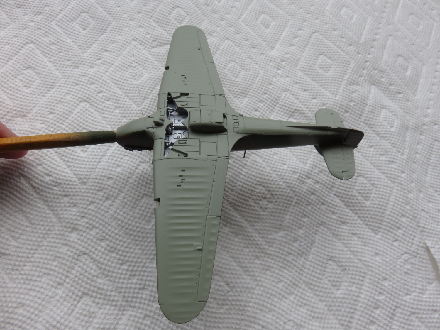
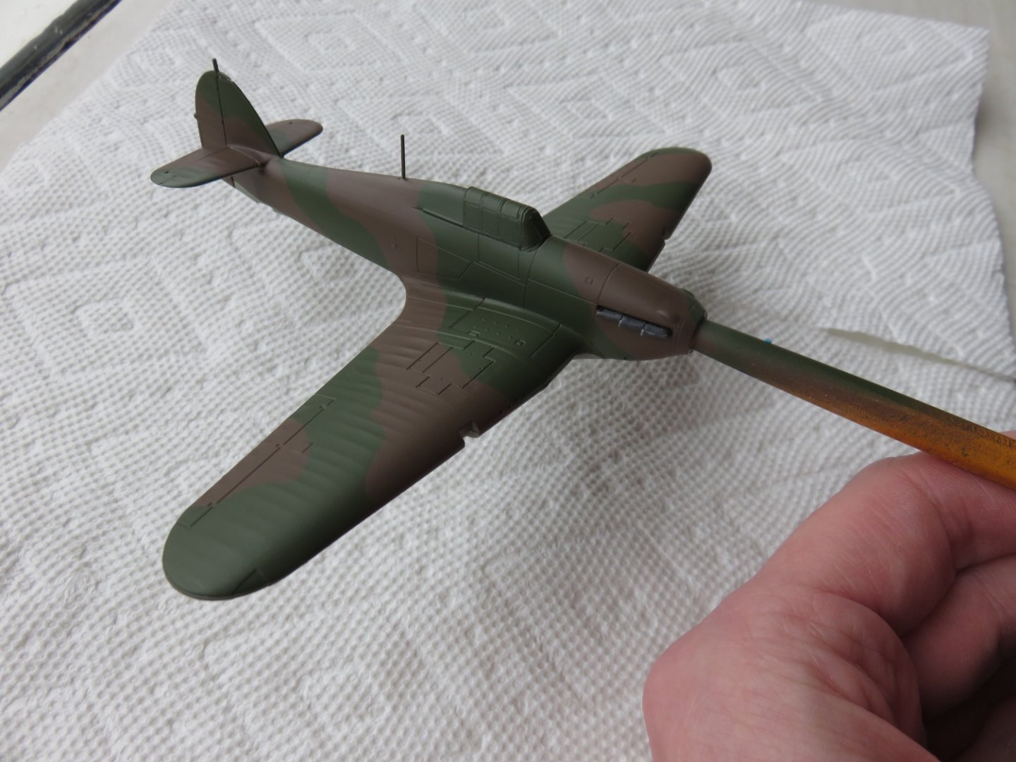
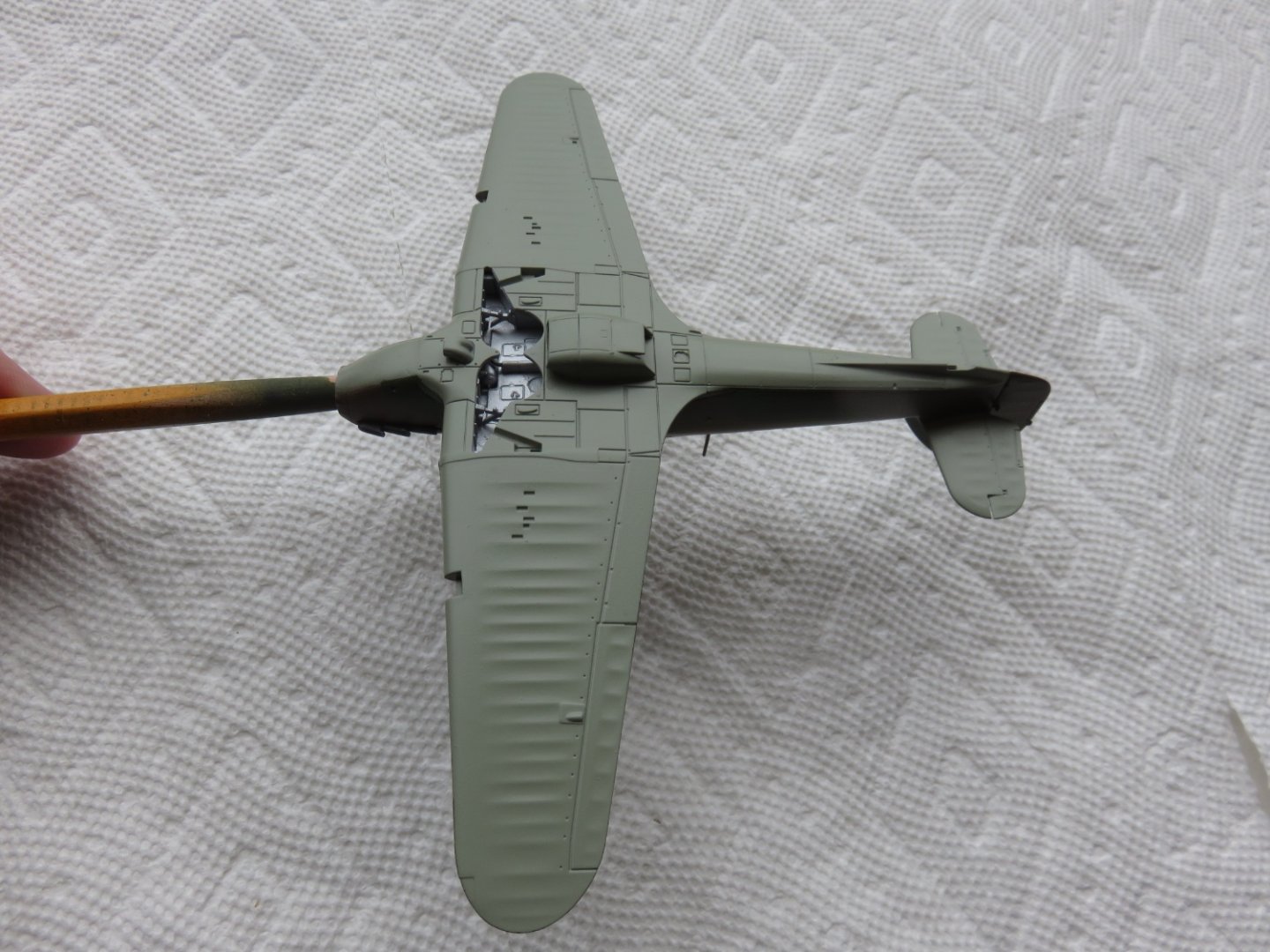
As always, thanks everyone for the comments and "likes". The last couple of days have been spent on painting. Mostly things went well, my only real issue came with my first attempt at the green camo bands. I had made them a little too skinny, almost anorexic. So I had to take a big risk and re-mask everything and make the green bands a little healthier. Luckily things worked out, excepting a few very minor areas in need of some touch up. I wish I could post some better photos, I don't have any really decent photography lights and the ambient light sucks right now (we've had nothing but thick dull overcast skies for almost a week straight, with no signs of it changing any time soon). Overall, I'm pleased with the outcome. I opted to use the lighter shade of RAF green (as opposed to the shade I used on my Wellington build). I thought it better represented a day fighter and it compares favourably with the grey/green underside. Next up after some touch ups and a layer of gloss will be the lettering. Hopefully there will be some sunshine by then. Andy
- 92 replies
-
- 13
-
-
Thanks! A lot for credit is due to Airfix. Not that I’ve a lot of experience with many airplane kits, but this one seems to almost fall together. They really designed this kit well. Andy
- 92 replies
-
- 10
-
-
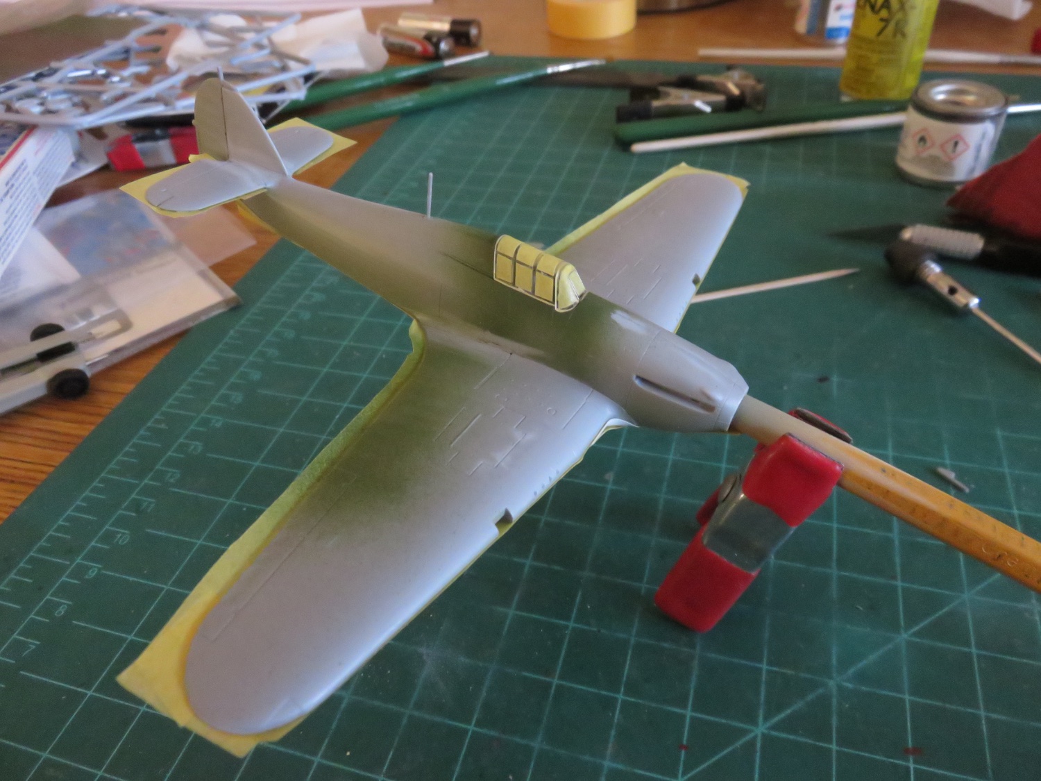
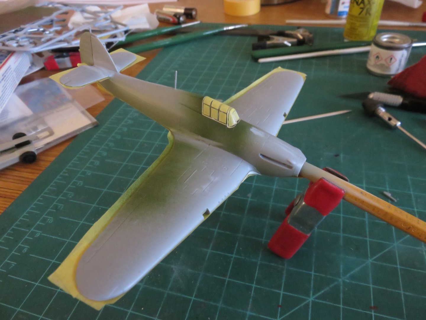
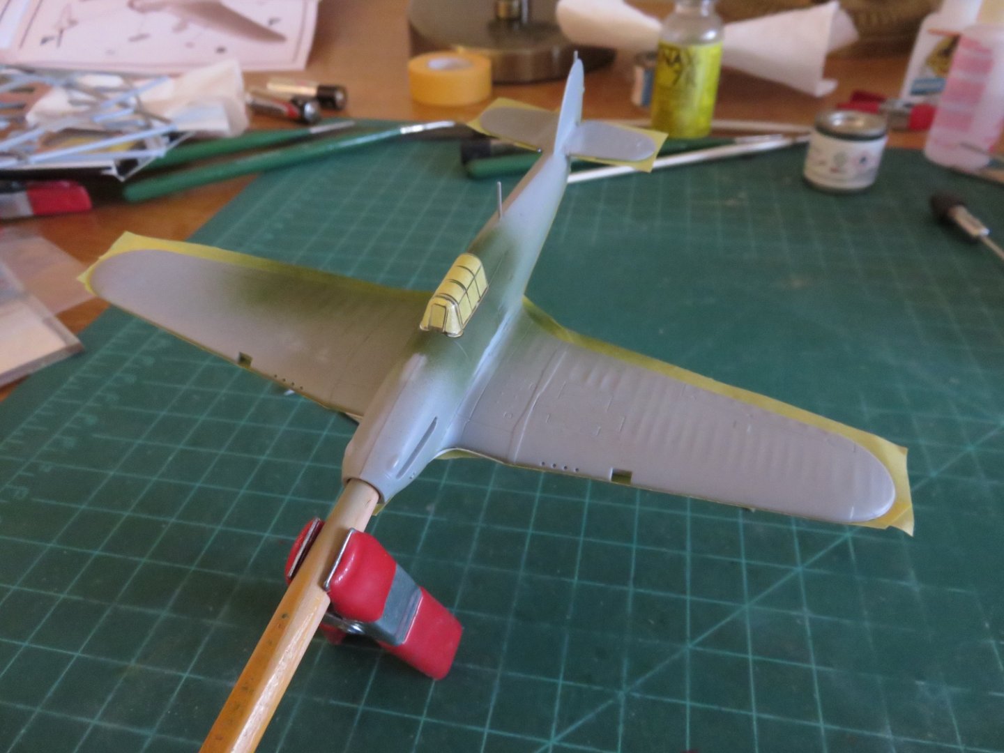
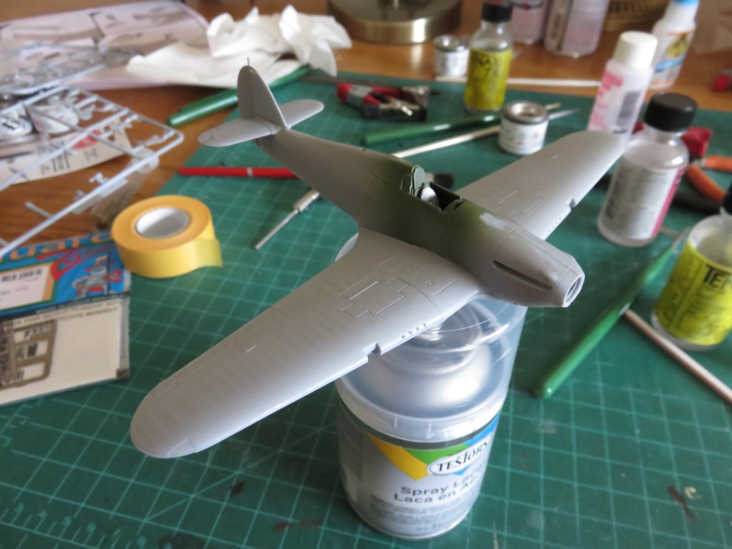
Thanks, everyone, for the likes. Always appreciated! So before I knew what was what, painting had started. The gap filling was not too excessive, and didn't take much time at all. I was too distracted by my progress I didn't take any pictures of the underside. Oops! You'll all have to wait for the reveal 😁. I did remember to snap a few quick picks after I'd masked off the underside: I figured I would challenge myself to make the canopy masks, rather than hunting for an aftermarket masking set. Seeing as it is a relatively simple canopy, it was far more economical to do it this way, and good practice for any future builds too! Just regular Tamiya masking tape, a fresh #11 blade and some patience (and a lack of the red leaky stuff that can emanate from one's fingers if one is not careful with the #11). I am pleased with the results. Prior to being glued in place, I gave the canopy a quick coat of Testors gloss to seal the tape edges. This should mitigate any paint bleed. Once the canopy glue has set, it will be back to painting. Andy
- 92 replies
-
- 14
-
-
-
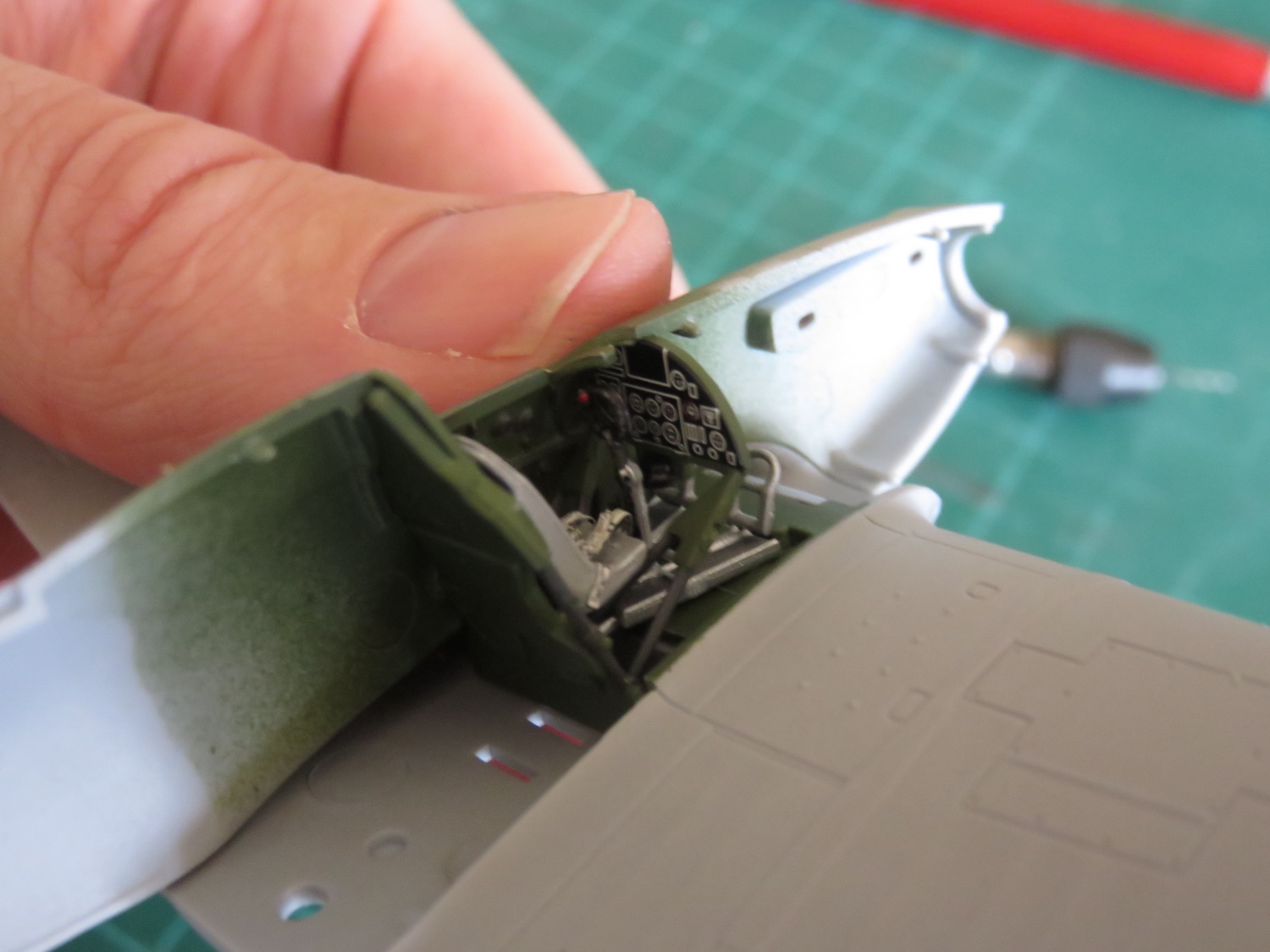
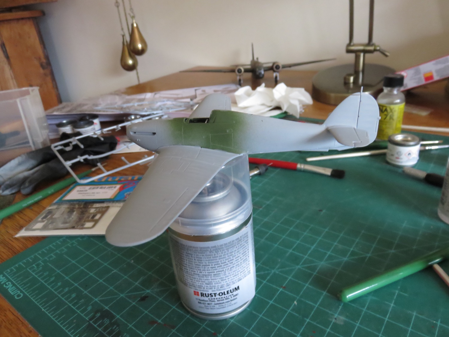
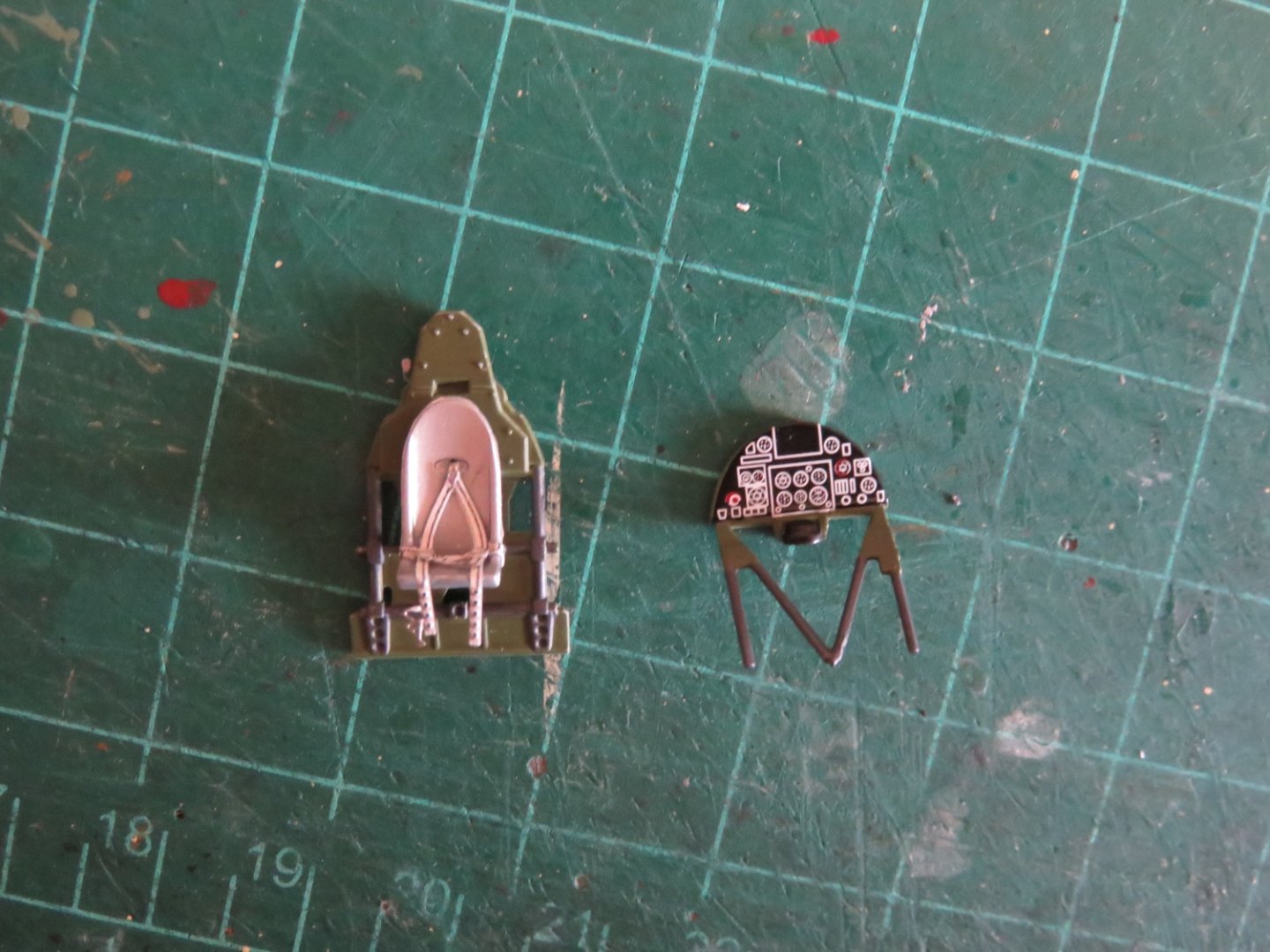
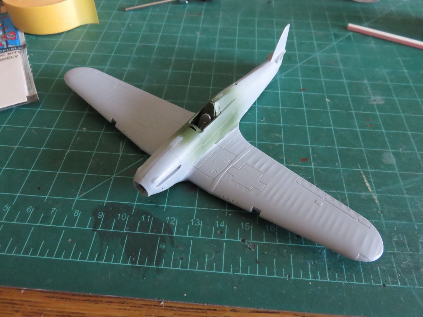
If nothing else, this build moves along pretty quickly. I left off yesterday about to finish the cockpit. Well, that didn't take too much of my time. All done. Very simple after all the complex fiddling about that I did building the Wellington. The seatbelts fit not too badly, and add a little touch of extra detail. The instrument panel was a basic decal. The heavy white lines actually make it slightly more visible (in a much smaller space) than the layered PE of my Wellington. A quick dry fit to make sure all the components will slide together nicely. I only had to tuck the ends of the seatbelt a little further under the seat to avoid them getting pushed up above the seat pan. For the most part I painted the interior green with aluminium components and gun-metal highlights on the details and various struts and whatnot. After the cockpit, things move swiftly and before long there was something that looked like an airplane. For the most part the fit was okay, but there are a few small seams that will need addressing with some filler. The after part of the wing/fuselage transition has the most obvious gap, but there are some small ones along the horizontal stabilizers and one the left side of the tail fin. There's also a bit of a lip on the chin of the plane, where the wing assembly meets the fuselage, that will need some sanding and maybe a little filler to smooth out the transition. I don't expect too much trouble dealing with these little areas. Andy


- 92 replies
-
- 15
-