
bolin
-
Posts
482 -
Joined
-
Last visited
Content Type
Profiles
Forums
Gallery
Events
Everything posted by bolin
-
Welcome! The Swampscott Dory was my first kit model boat as well. It was a really good introduction.
-
 Your start with the deck planking looks good. Keep it up and the model will turn out excellent.
 -
Sloop from Roslagen by bolin - FINISHED - 1:50
bolin replied to bolin's topic in - Build logs for subjects built 1851 - 1900
Yes, they are quite sturdy. My research has led me to 25 cm wide and a 30 - 35cm thick. I am a bit uncertain if they where made as single or double frames. As discussed earlier the evidence is scarce and therefore inconclusive. -
Sloop from Roslagen by bolin - FINISHED - 1:50
bolin replied to bolin's topic in - Build logs for subjects built 1851 - 1900
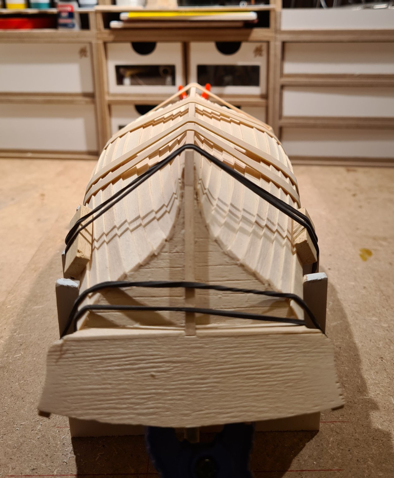
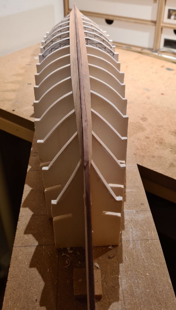
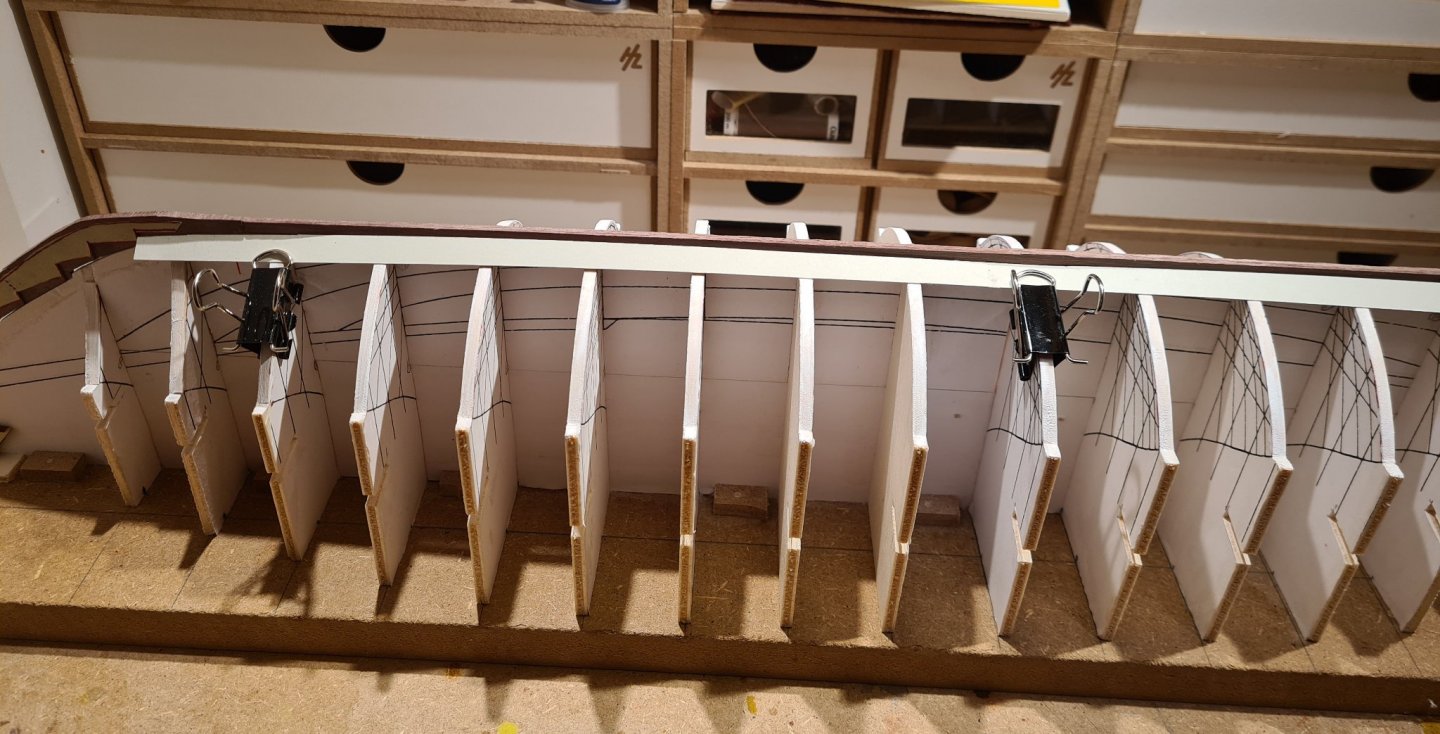
As promised, a bit of an update of the progress. I have glued in the first and last full frames, and have started to fit in the rest. I will wait with gluing them in until I have the full set, and can use some small distance pieces between to get the spacing evenly distributed.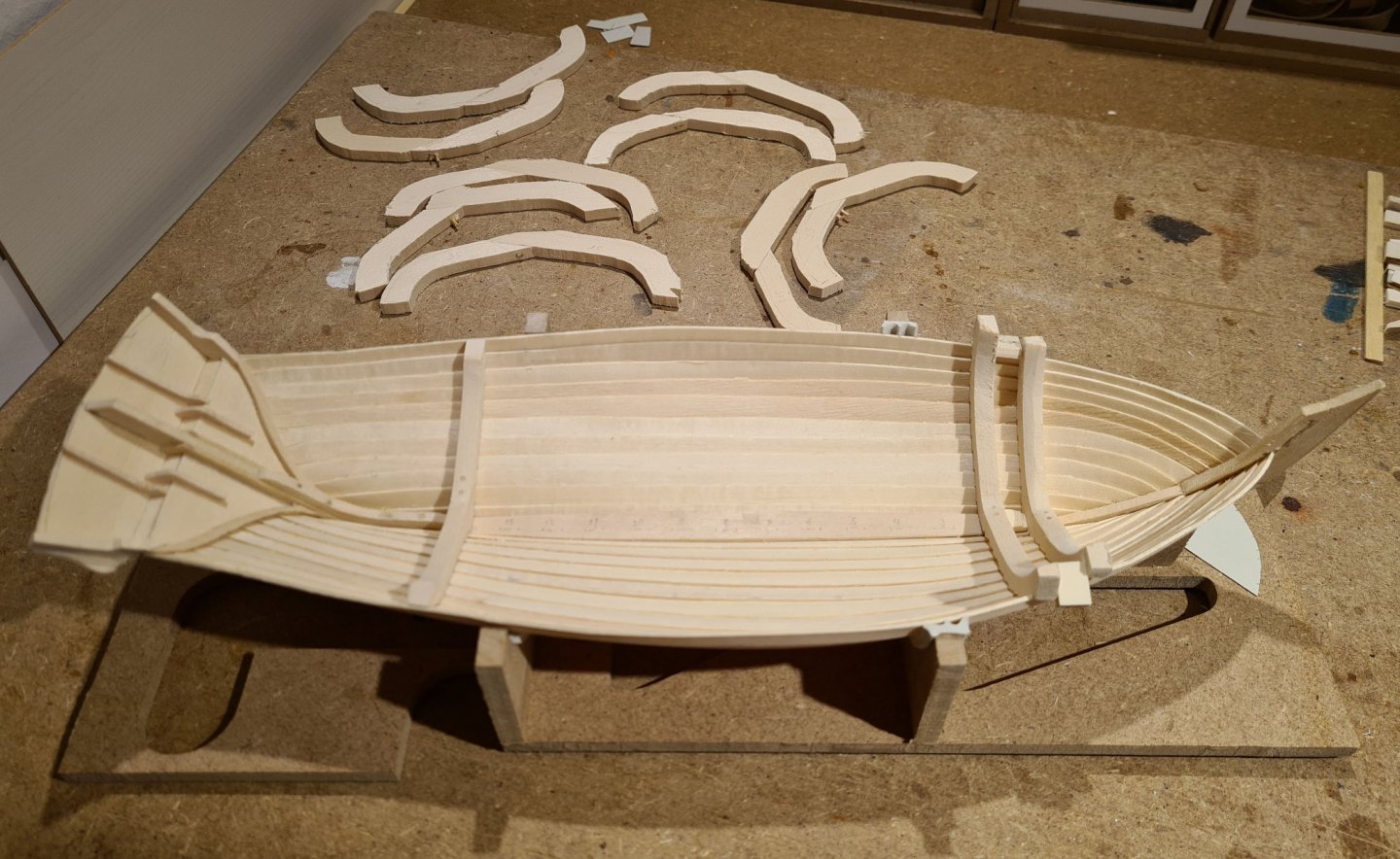
-
Sloop from Roslagen by bolin - FINISHED - 1:50
bolin replied to bolin's topic in - Build logs for subjects built 1851 - 1900
You are most welcome to the show Håkan. I hope that you will find the inspiration and opportunity to continue your Kågen. This build has slowed down a bit as well lately, as I have focused more on my medieval long ship. But some progress has been made and it’s time for an update. -
Thanks Louie, it feels like a big step. I have now added the last planks in the fore and aft, and have started to construct a new build slip. I still have need for the old mold a while longer while I drill the holes for the rivets. It's tedious work, but nothing compared to what it will be to actually install the rivets...

- 179 replies
-
- 14
-

-
- longship
- Helga Holm
- (and 1 more)
-
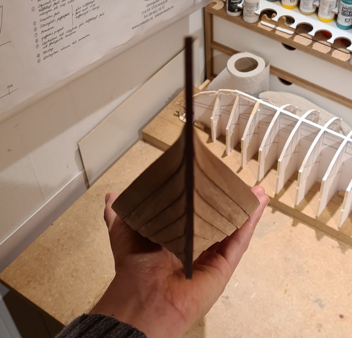
Thanks Eric, you are welcome to tag along. Now I have reach the state when the shell of the hull is almost complete. There is one partial strake to add in the fore and aft. In the mid section the rowers will sit, so the sides cannot be as high. Initially I thought that I should add those planks after I had put the frames in. But now I realize that they will be easier to get in place with the correct angle while I can still use the mold. But in order to do that I need to modify the mold slightly. So I lifted the hull from the mold and took the opportunity to scrape some glue away.

- 179 replies
-
- 15
-
-
- longship
- Helga Holm
- (and 1 more)
-
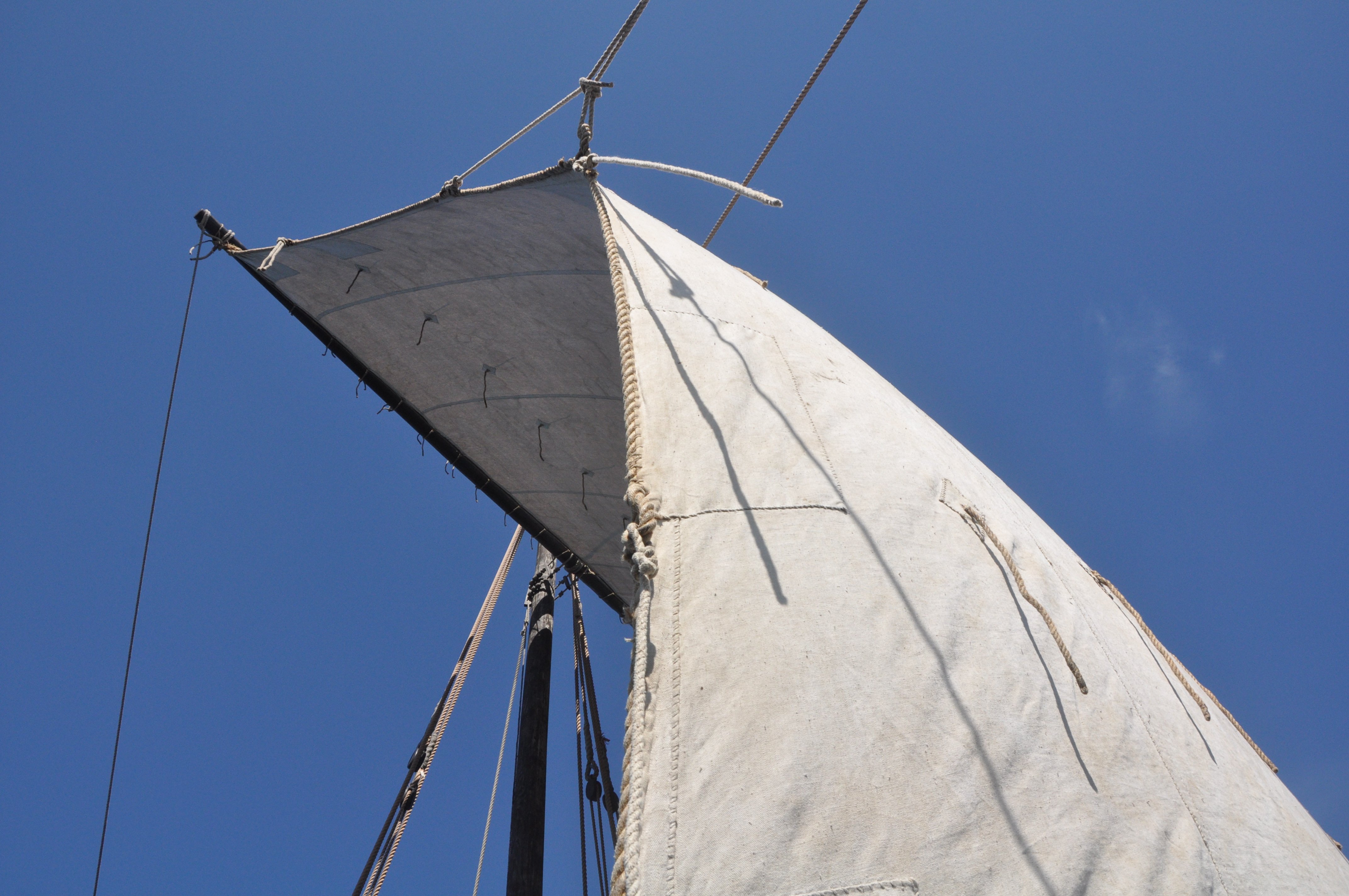
Nice details you are adding to your model. I especially like the bucket and the sail. The tissue paper actually looks quite realistic. Well done.
-
That could probably work. I will see what I can find. I have also considered plastic sheet. The experimentation will continue.
- 179 replies
-
- 3
-
-
- longship
- Helga Holm
- (and 1 more)
-
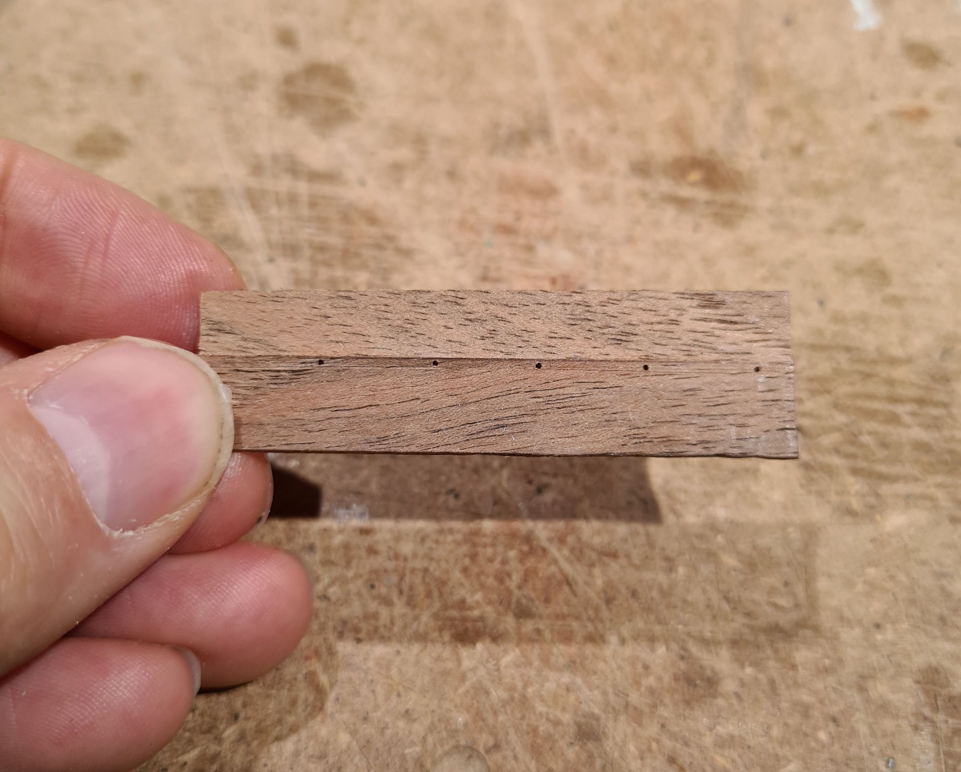
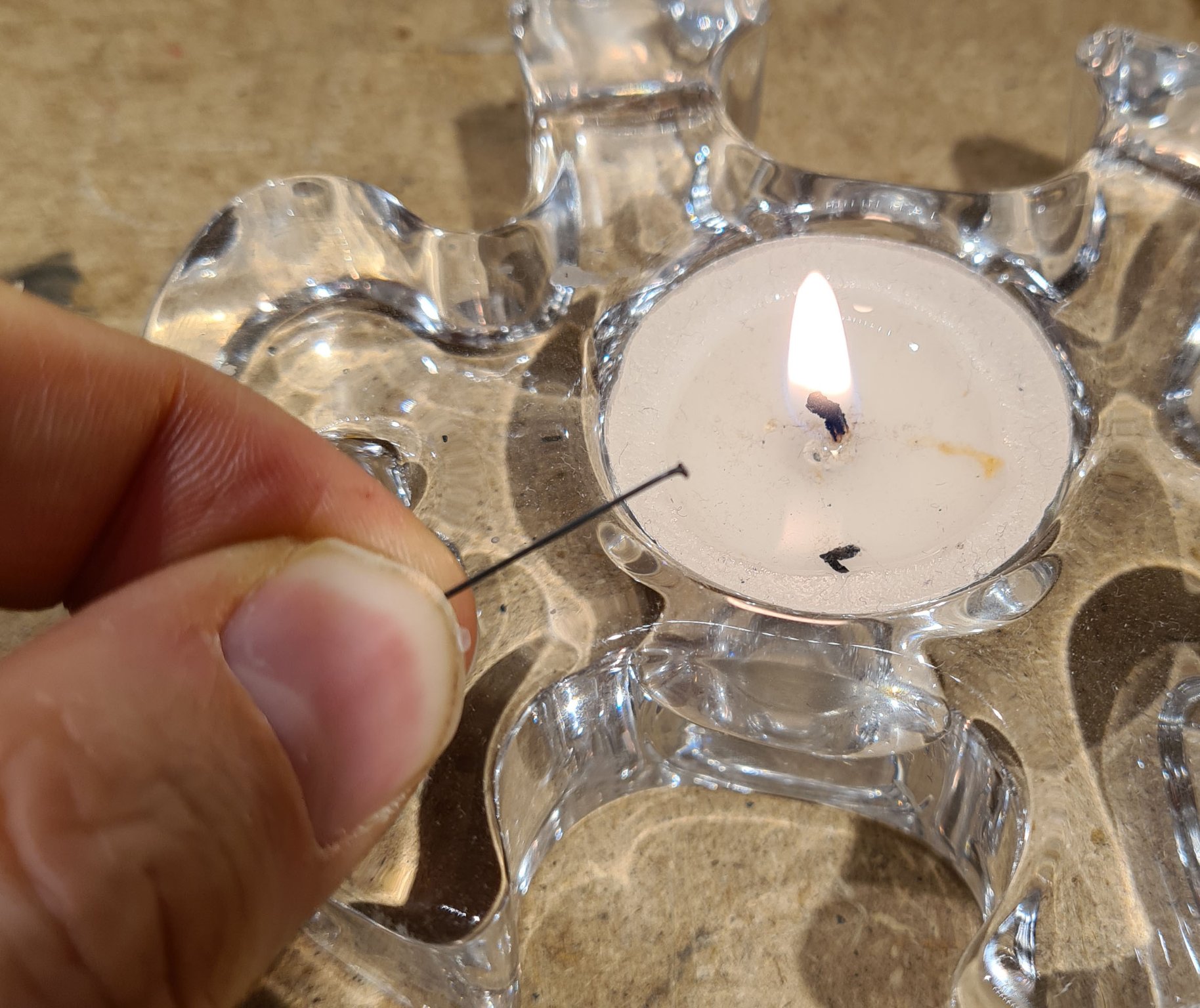
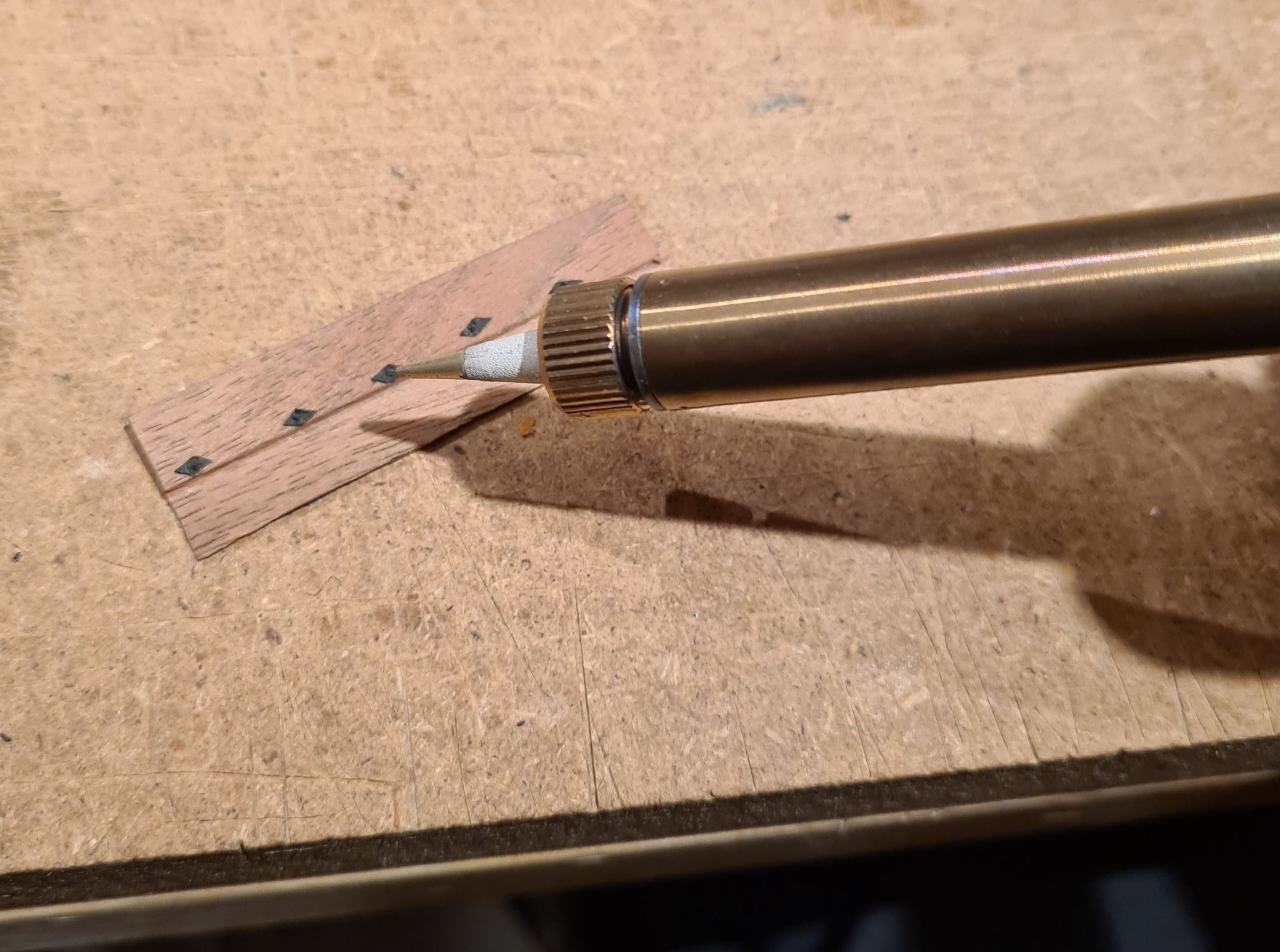
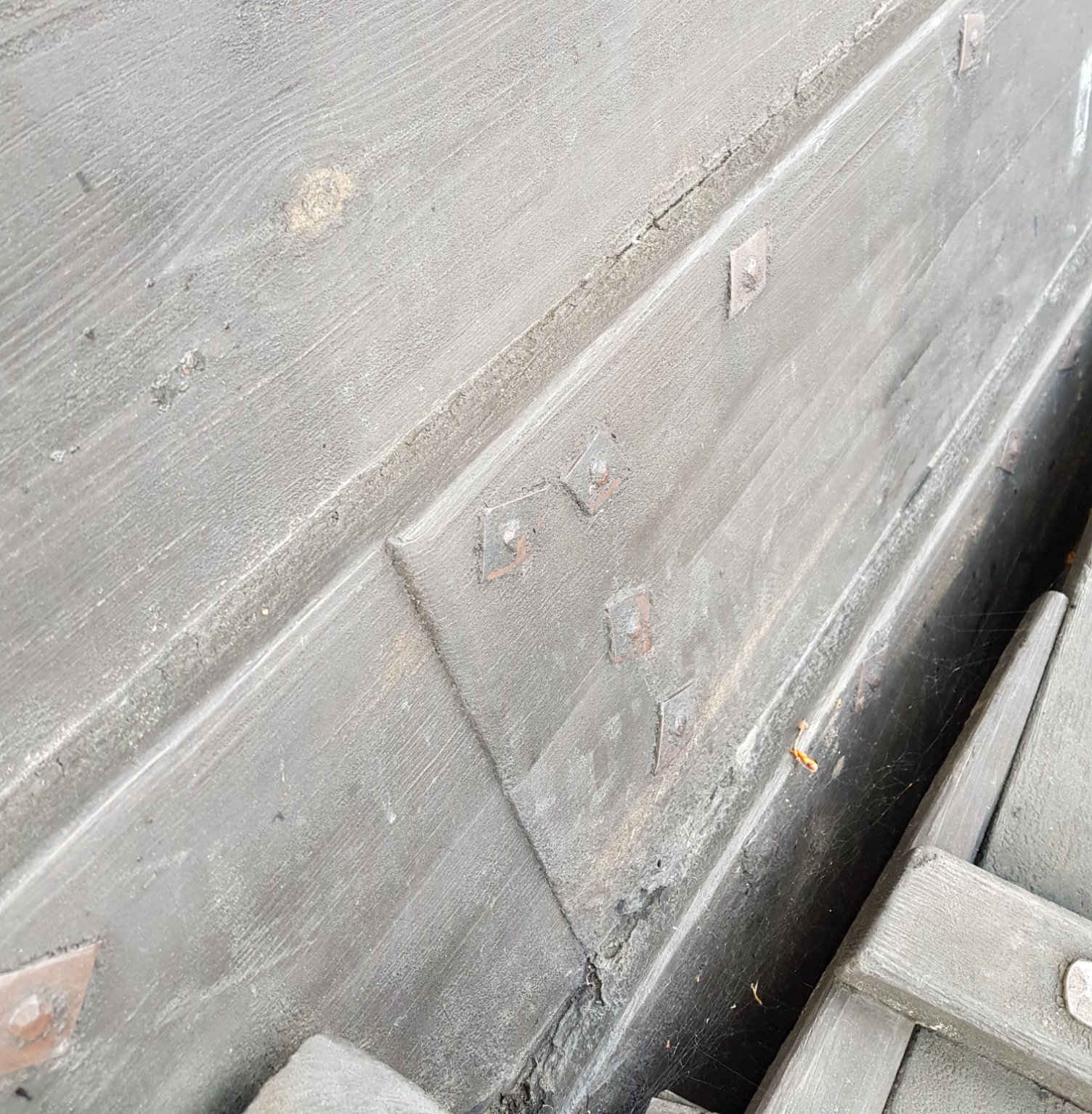
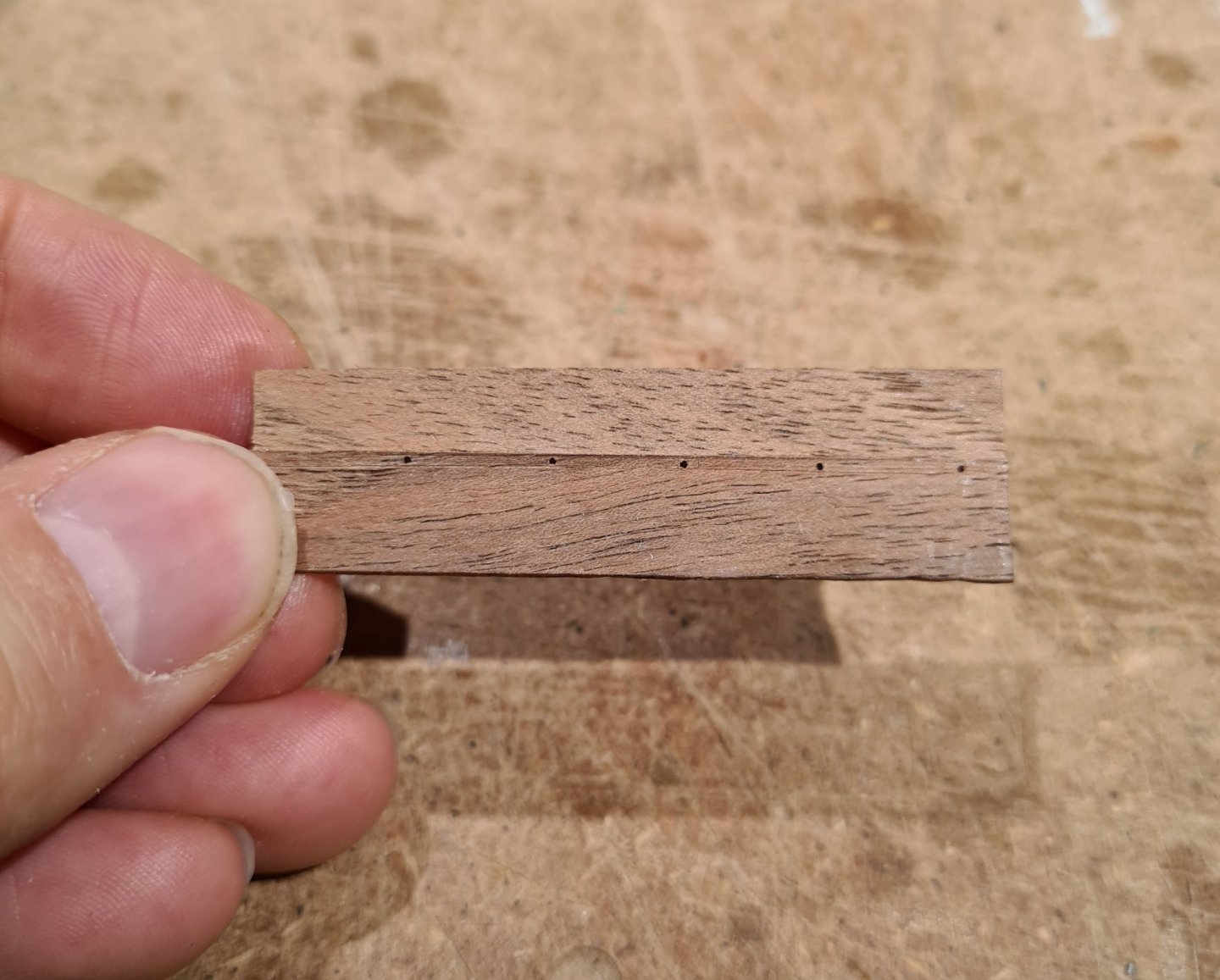
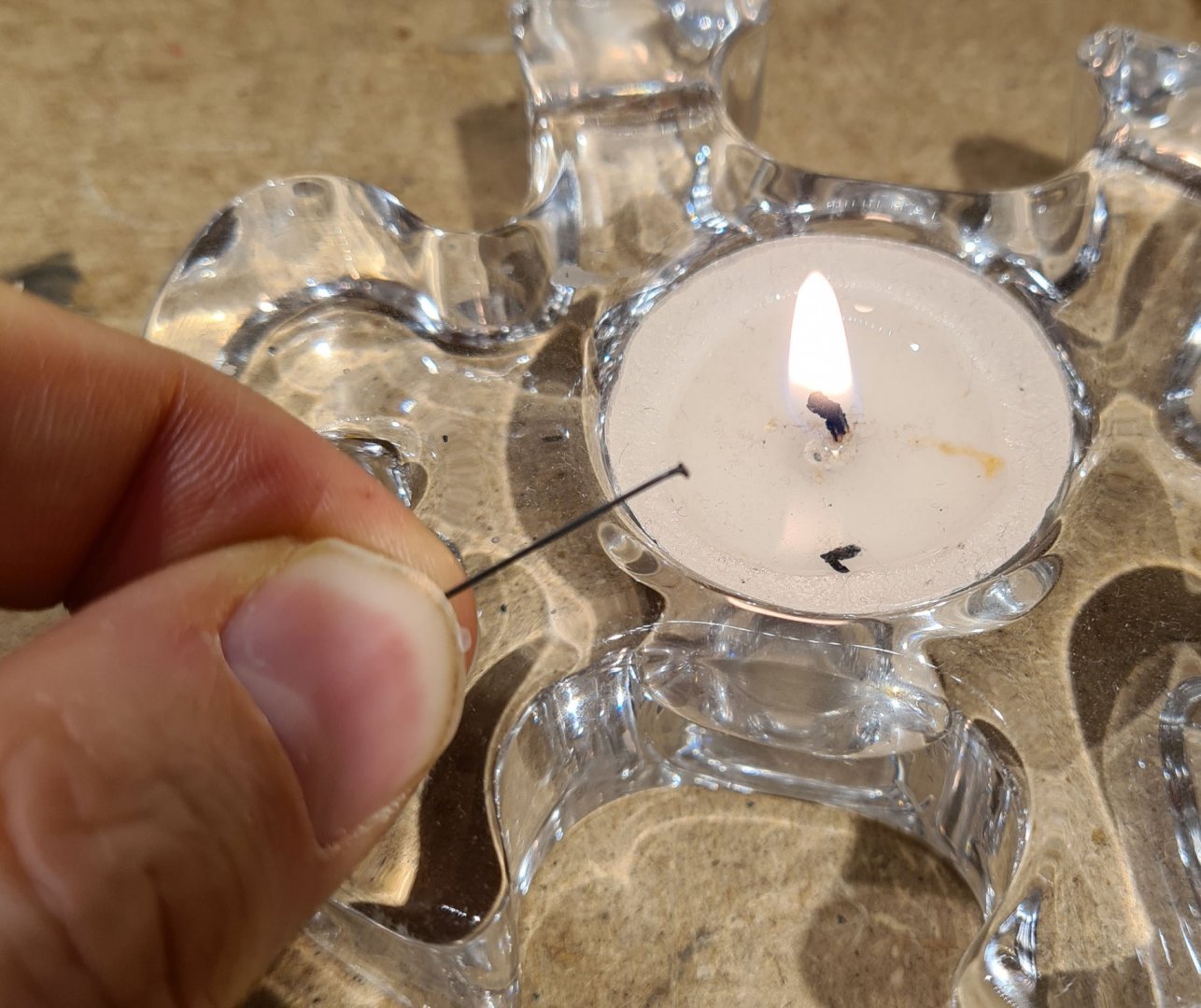
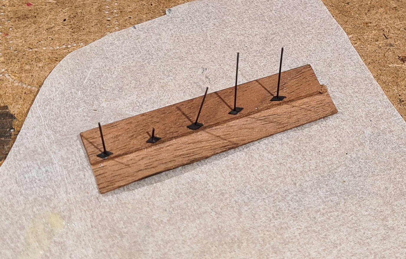
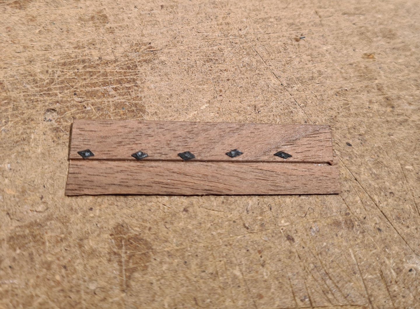
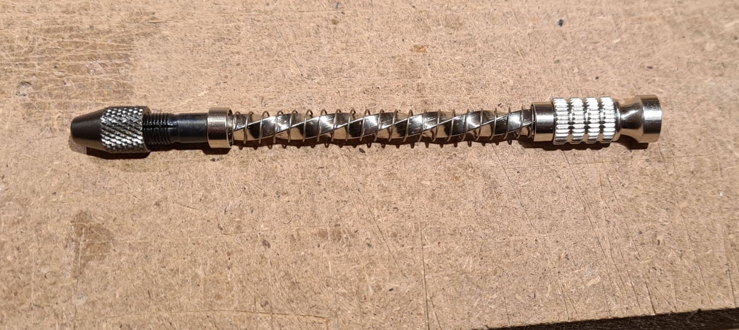
I have been experimenting a with rivet construction today. I think I have a method that will work OK for 2000 rivets, and can be made to look good scale wise as well. First I drill holes for the rivets. I got a new drill holder for this, an "archemedean" screw type. I already have a pin vise and a Proxxon electrical tool. However I think my fingers will tire if using the former, and the risk of the drill jumping and leaving marks on the hull when using the second is to high. A few holes: The rivets are made from a dish brush bristle. They get a head by melting the end in a candle. The rivets are then pushed through and the plate on the other side is added. These are made from painted cardboard and is given a small drop of glue beneath to stay in place. Scale wise the plates are too large, maybe I need some better cardboard. The pins are then cut and the ends are flattened using a soldering iron. The outside The rivets should be about half the distance apart, but otherwise I'm quite happy with the result. A picture from the reconstruction
- 179 replies
-
- 12
-
-
- longship
- Helga Holm
- (and 1 more)
-
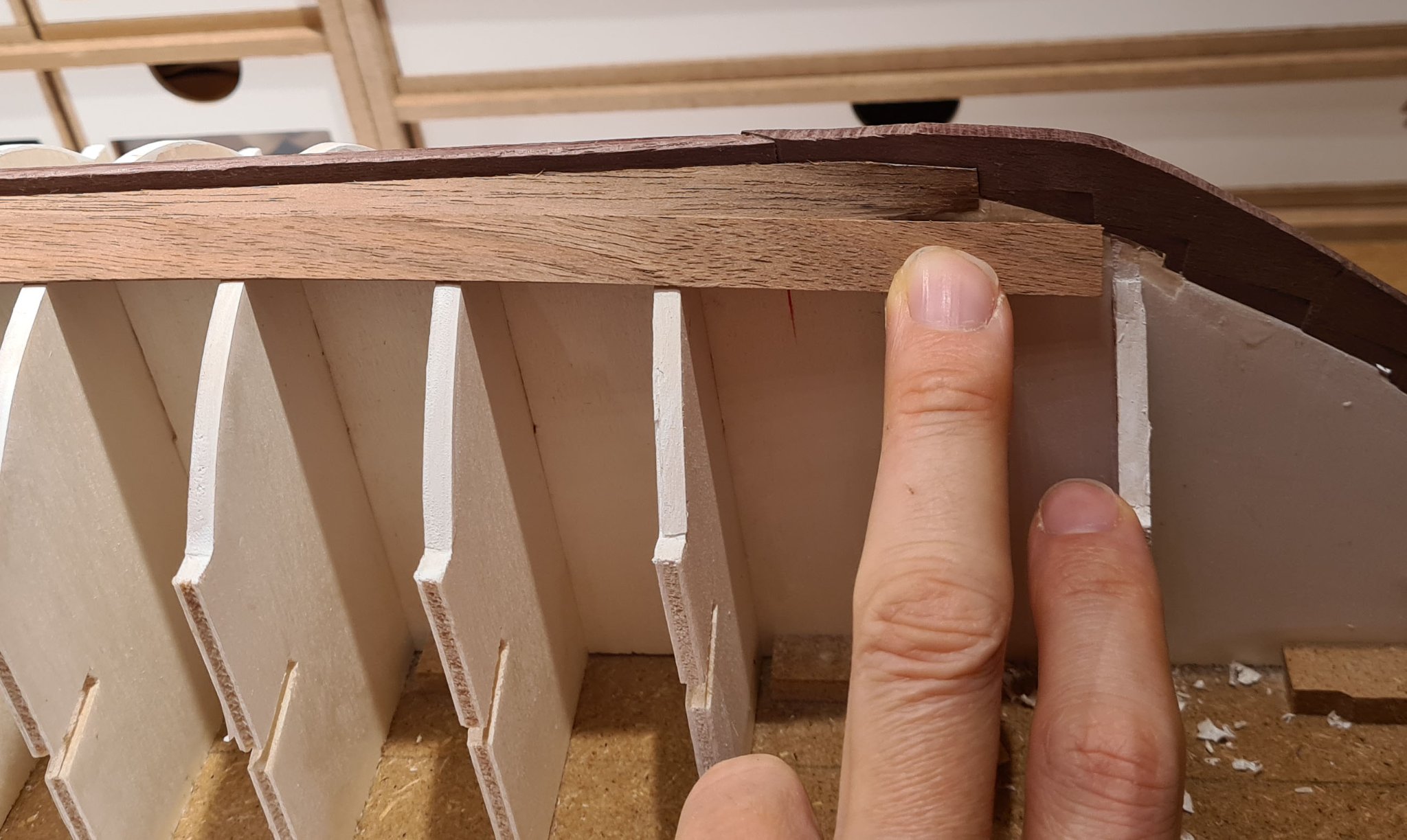
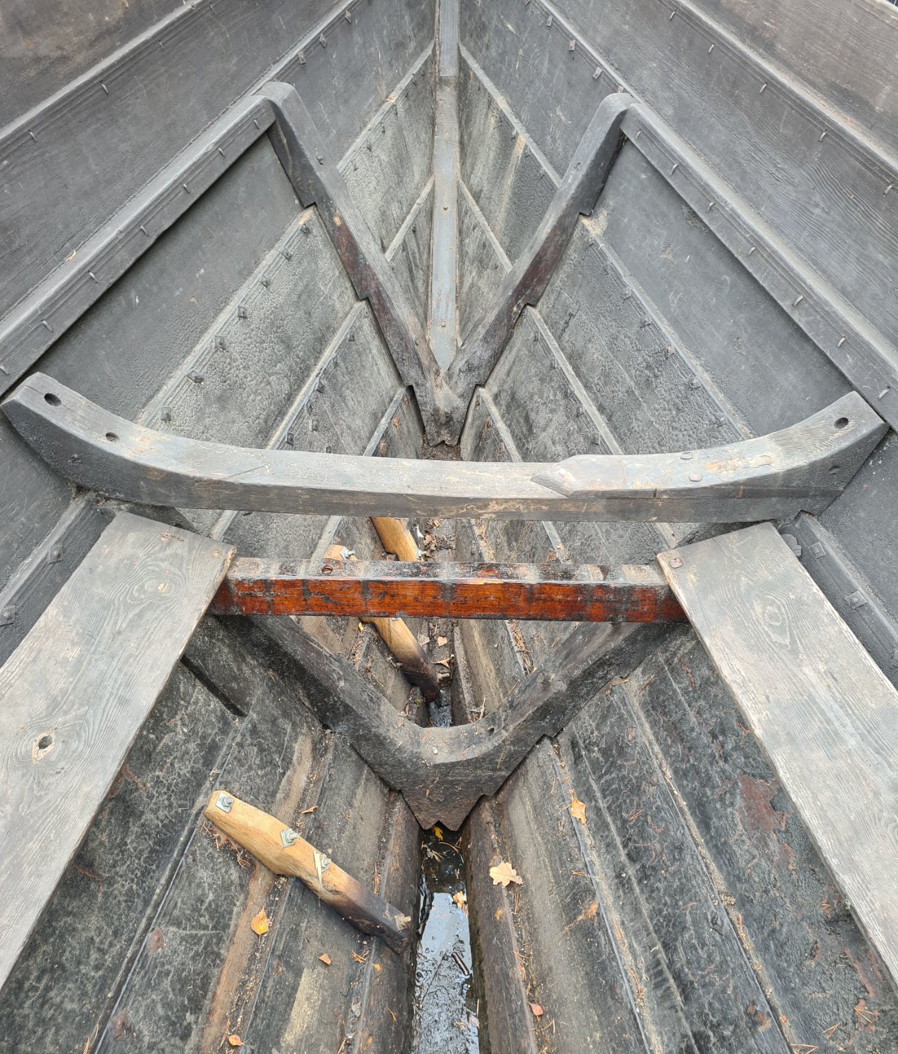
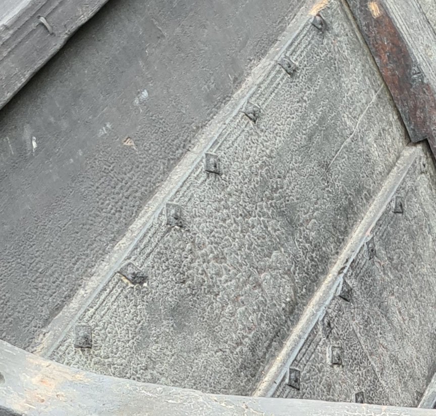
Its a scarf joint. I'm trying to replicate whats shown in the picture below. If you look carefully the joint, and the angle, can be seen.

- 179 replies
-
- 6
-
-
- longship
- Helga Holm
- (and 1 more)
-
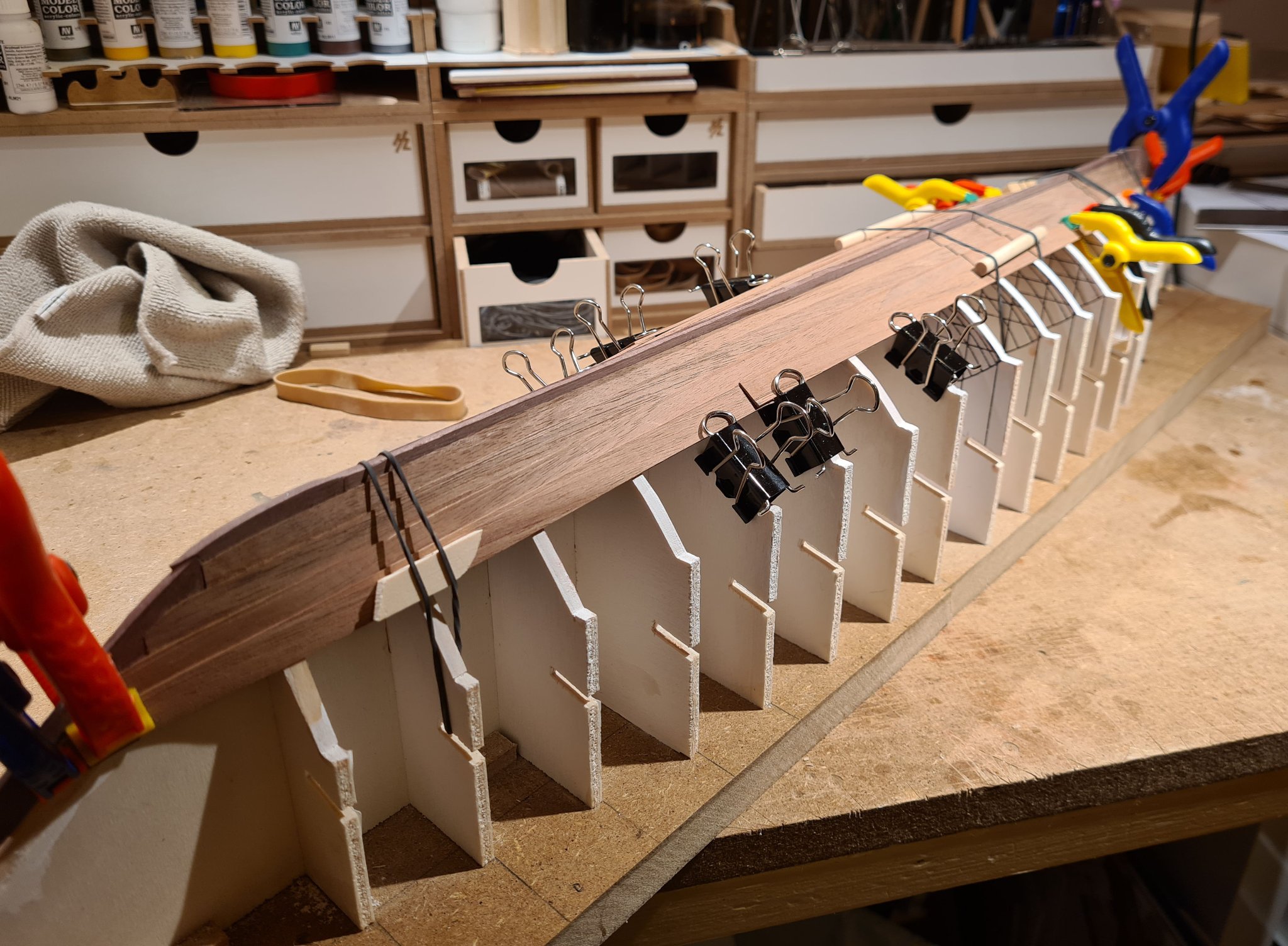
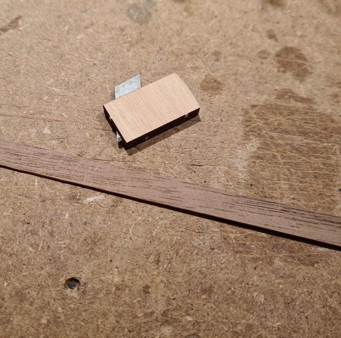
Forth strake fitted, soaked and bent to shape on the mold. The third and fourth consists of two planks that are joined with a bit of overlap as on the real ship. This gives me some wiggle room in adjusting the length of the planks to fit in the rabbets. On the picture below I have not thinned down the end of the longer uppermost plank. I will do that when I have glued the first planks and know exactly what length the plank need to be.

- 179 replies
-
- 10
-
-
- longship
- Helga Holm
- (and 1 more)
-
Another interesting subject from you. This will be enjoyable and educational to follow!
-
Sloop from Roslagen by bolin - FINISHED - 1:50
bolin replied to bolin's topic in - Build logs for subjects built 1851 - 1900
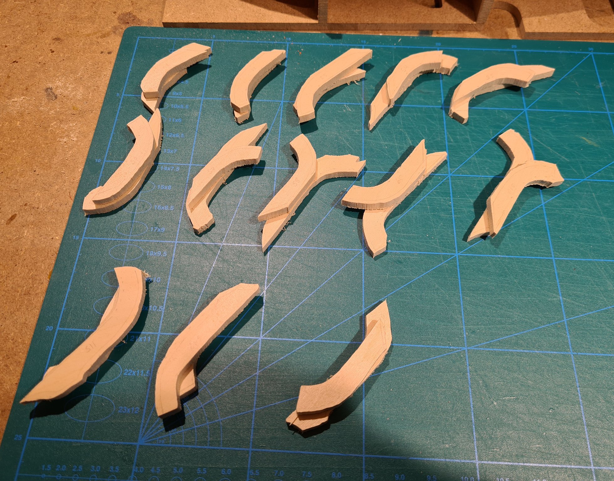
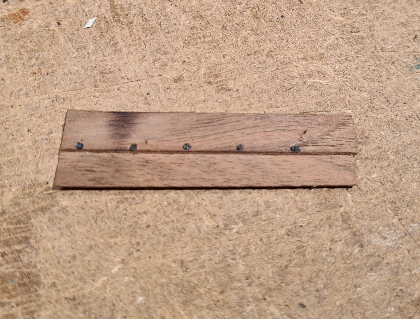
The small gap is in Swedish called våghål, which translates to wave hole, and its purpose its to let the water flow freely. I have continued with the frames. First I have made templates by interpolating the body plan between the stations, and then adjusted against the actual form och the hull. Then I have cut the pieces for the frames. I have decided to make each frame from two pieces. I don't have any firm evidence of how many pieces there would have been. I have made the assumption that the frames where made of naturally bent timber that where joined somehow. The pieces joints are asymmetrical, and I plan to place them alternately on port and starboard side. I have reinforced the joints with tree nail.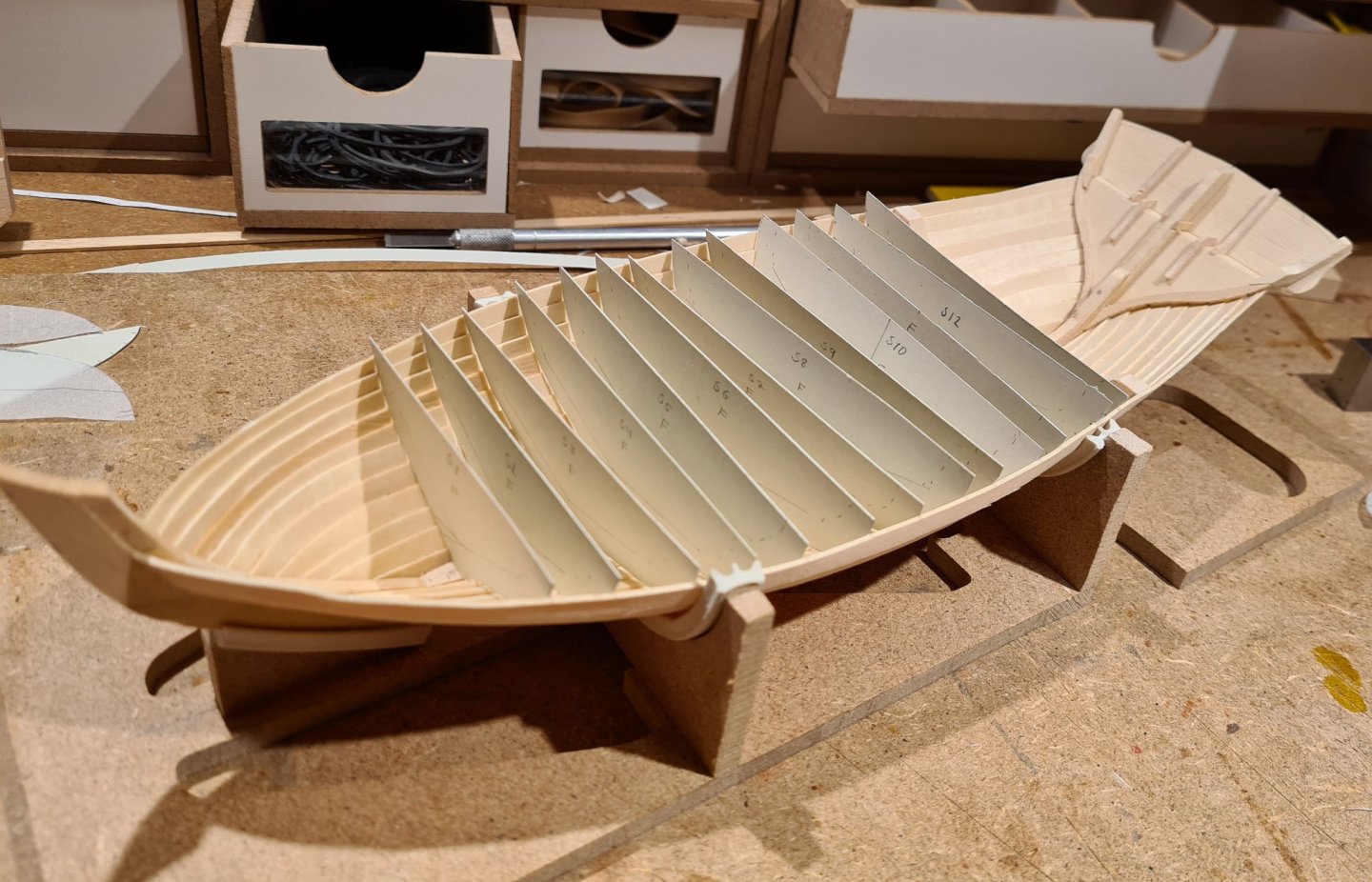

-
Stitching sails with sewing machine
bolin replied to Jorge Hedges's topic in Masting, rigging and sails
I would suggest making the sail cloth stiffer before putting it into the sewing machine. I have used matte spray varnish, and then ironed the cloth to get it flat. For the hems along the sides I have folded them and then used glue to hold them down. Pins in these small dimensions will make the cloth warp and a straight line is very hard to get. I would also suggest giving up un the sewing machine and hand stitch the hems. You have much better control of what you are doing then. Especially when putting a line along the side of the sail, then hand stitching is the only way to go. -
Thanks durxey, I will try that. It would also be more realistic as the real ship (both the original and the reconstruction) has strakes made out of more than one plank. My idea thus far has been to fake the joints by scratching a mark in the plank and add a number of rivets to indicate the joint.
- 179 replies
-
- 6
-
-
- longship
- Helga Holm
- (and 1 more)
-
Sloop from Roslagen by bolin - FINISHED - 1:50
bolin replied to bolin's topic in - Build logs for subjects built 1851 - 1900
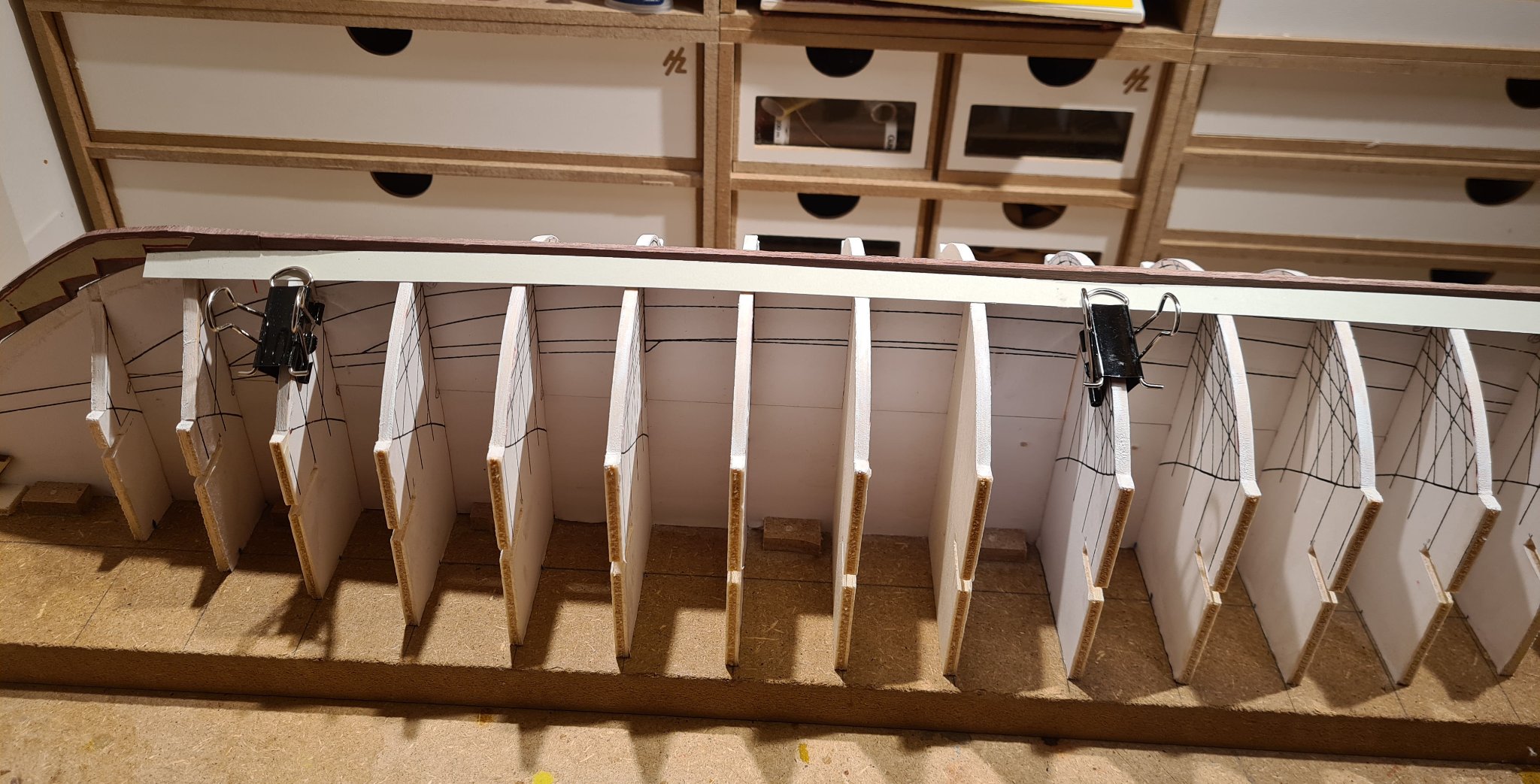
I have decided to make the frames 5 mm wide, with a frame every 12 mm. This correspond to 25 cm wide frames every 60 cm. Here I have installed the first frame. There will be 14 full frames and 3 cant frames in the bow and rear. The first frame was more of a test on a method to build them. For the rest I will make several at the same time.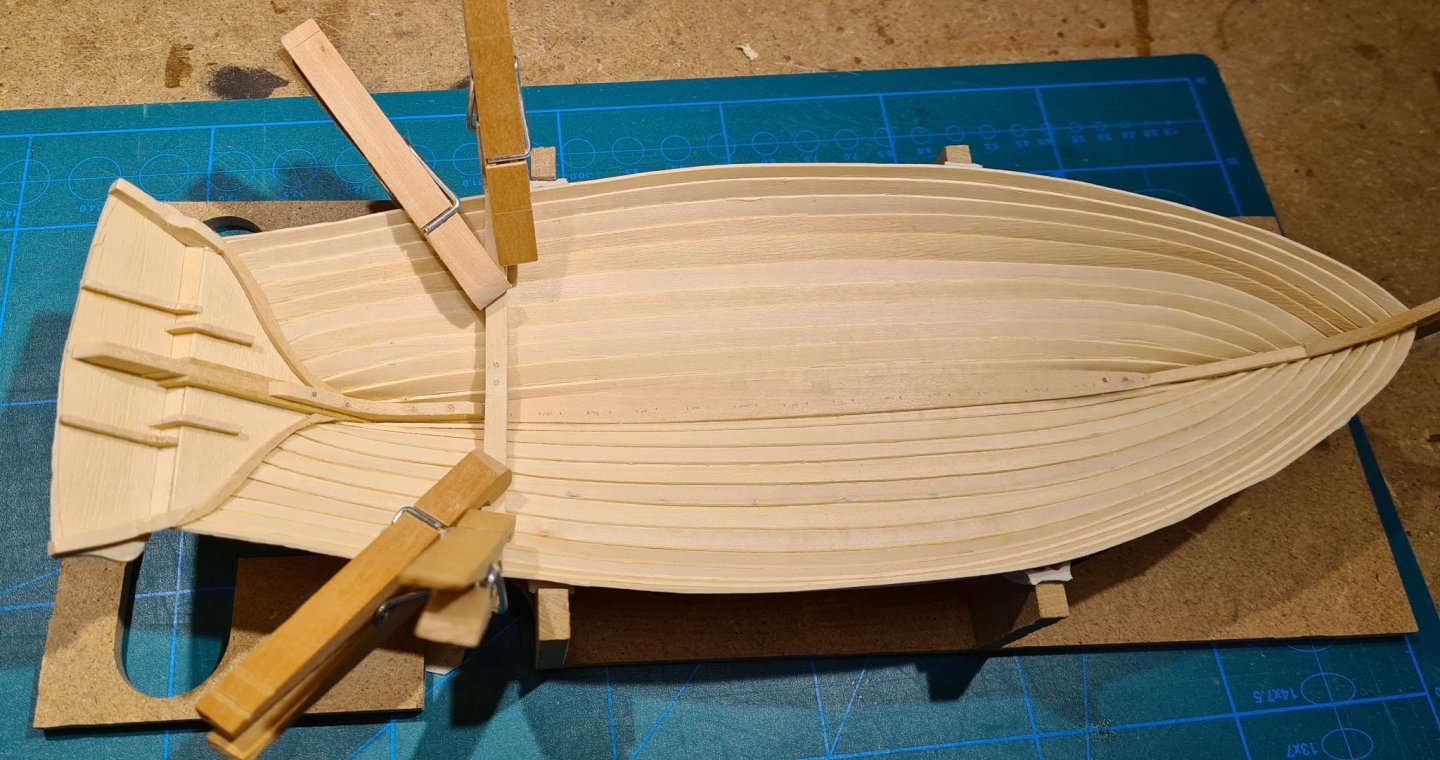
-
I cut the second plank and started to fit it today. There seem to be a problem. When the plank lies flat and nice on most of the frames it does not go into the rabbet. There are some photos from when the reconstruction was built. The planks are quite straight, and used in more or less their full width all the way to the ends. They are only bent and twisted, no edge bending or splicing. I have an idea of what my problem is, and I have created it myself: If I just bend and twist the plank as it naturally goes it could reach the rabbet, if the frames where narrower and the bow was more concave. I will need to sleep on this.

- 179 replies
-
- 6
-
-
- longship
- Helga Holm
- (and 1 more)
-
Thanks, I do want this to be a nice model. Since the reconstruction will soon no longer be in condition to sail, I build the model to have a something to remind me of all the nice times I have had onboard. In a way I have even planned my previous builds to learn the skills to make this a nice model. I hope I will succeed.
- 179 replies
-
- 4
-
-
- longship
- Helga Holm
- (and 1 more)
-
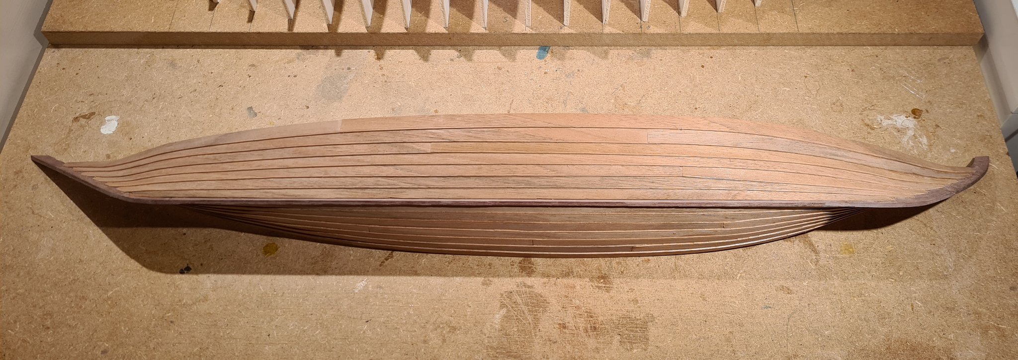
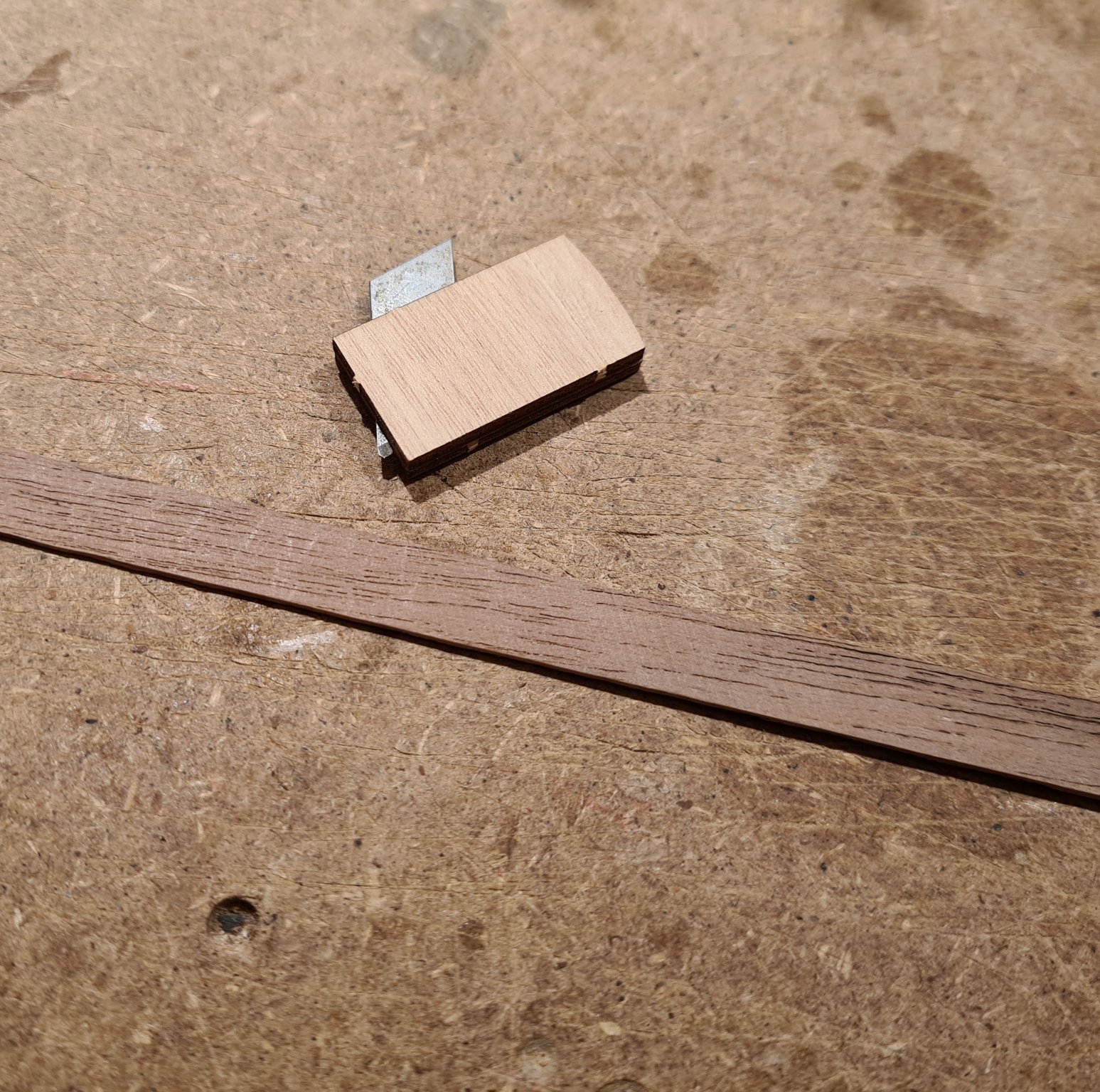
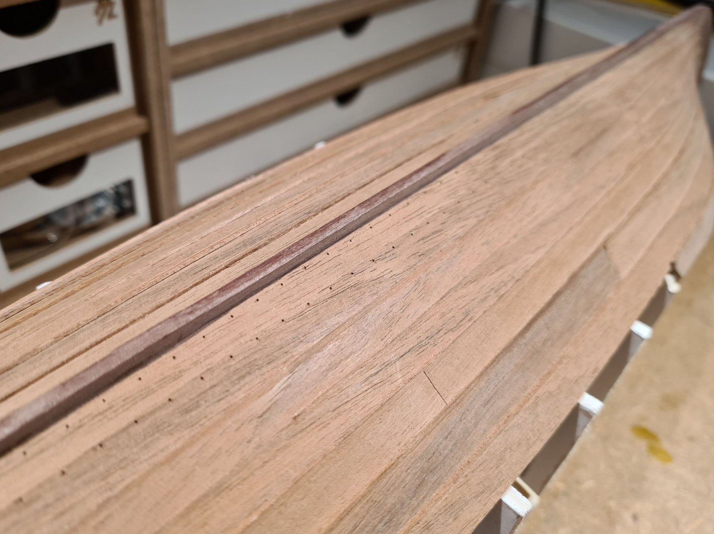
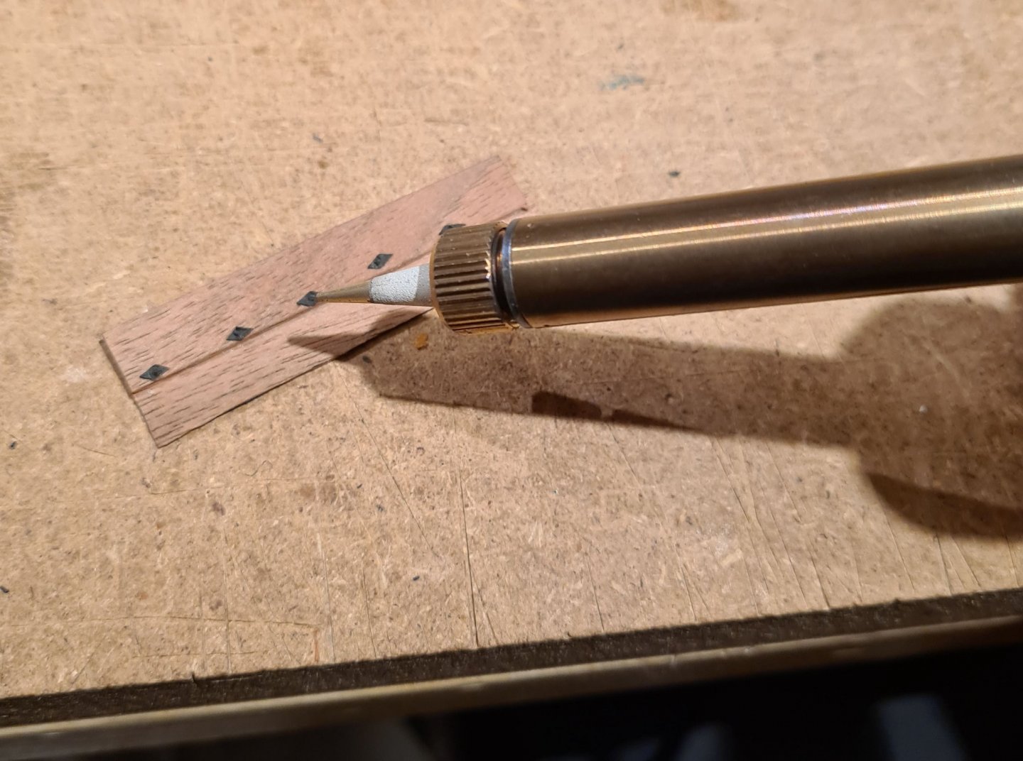
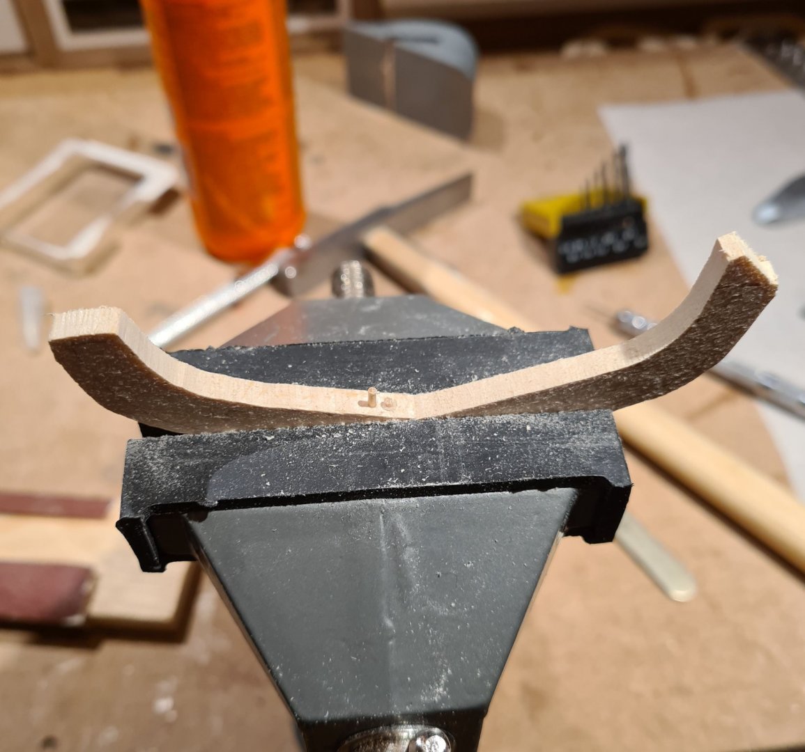
The planks did shrink after they dried. One was still to long, so I had to shorten it slightly to fit in the rabbet without bulging on the middle. Before I install the next strake I will bevel the edge of the already installed planks to the correct angle. To do that I have made a special sanding block with the same width as the planks that I can run along the planke edge and ride on the frame molds. (I learned this method from @druxey in his excellent build log for the Greenwhich Hospital Barge.) Each plank will also get a decorative groove along its length. In the original find, and on the reconstruction, there are three parallel groves. I have made a small tool from a blade that I have filed down all but 1 mm of, and glued between to pieces of wood. I run i to run along the edges of the planks to create similar grooves. My tool creates more like a band, than three distinct grooves. But considering the scale and that the grooves are almost invisible in full scale, I'm OK with that.


- 179 replies
-
- 13
-
-
- longship
- Helga Holm
- (and 1 more)
-
Sloop from Roslagen by bolin - FINISHED - 1:50
bolin replied to bolin's topic in - Build logs for subjects built 1851 - 1900
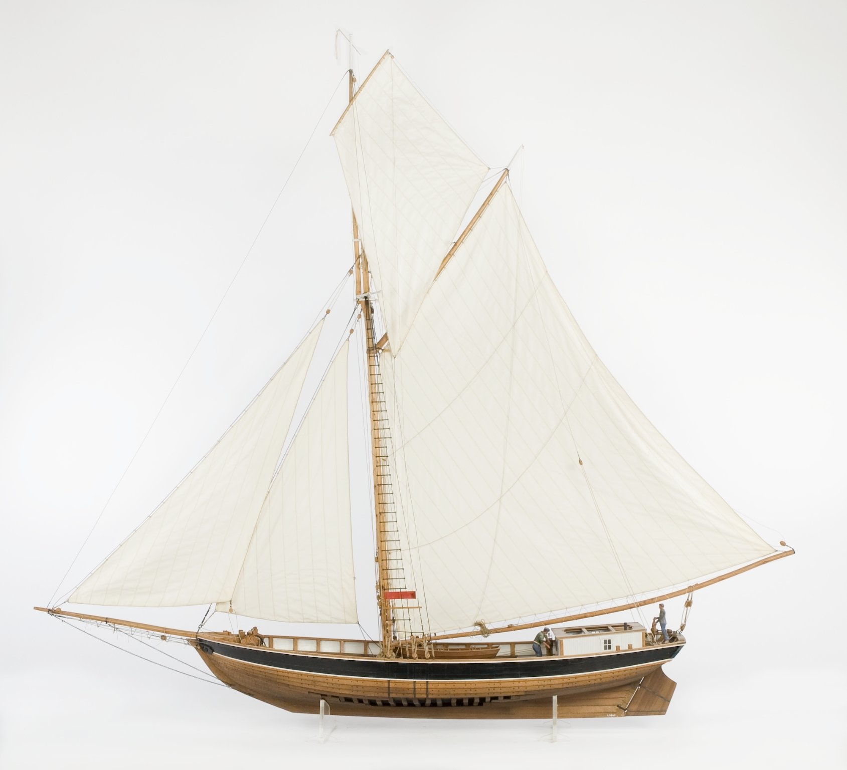
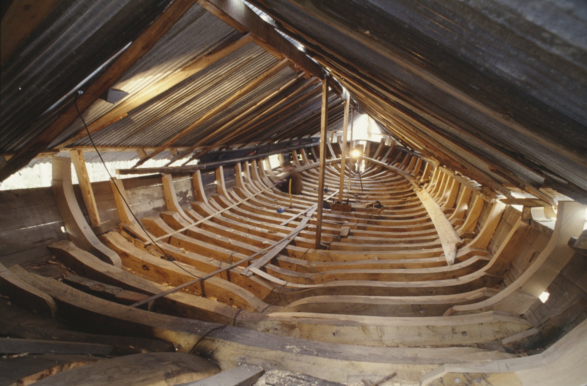
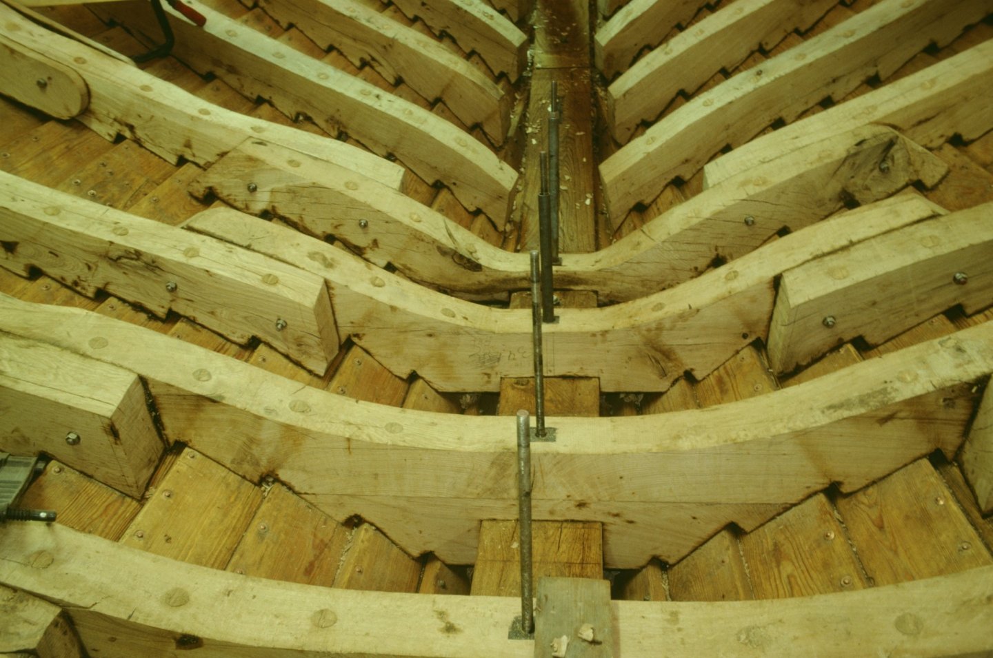
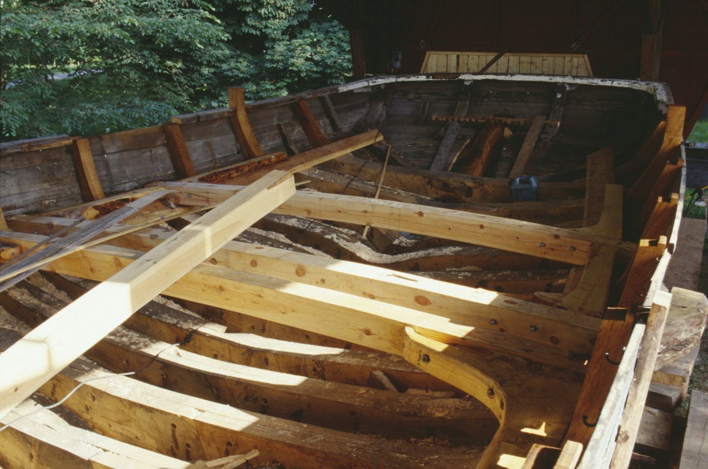
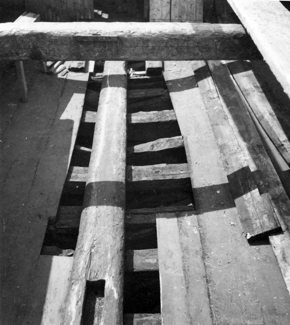
Before I start the framing I have a bit more research to do, or at least some decisions to make based on the research I have done. As I have mentioned the plans I'm building from does not have any information about the inner structure of the hull. There are to my knowledge no plans preserved for any of these boats. Mainly since they where (with a few exceptions) not built on shipyards, but by traditional methods and with more rules of thumb than plans. So when it comes to the frames I need to figure out how many they should be, what space there should be between them, how thick should they be? I have found a number of sources, and will need to use my own judgment on the most likely look. There is one sloop for which there is a reasonable amount of information available. The original was called Greta Linnea and was built in 1921, as the last sloop of this kind. There was a model built in 1931, which was commissioned by the maritime history museum in Stockholm as a documentation of a type of ship that was quickly disappearing. Therefore I can assume it is quite accurate. The model gives some idea of the thickness and spacing of the frames. In the 1980s a reconstruction of the same ship was built, named Sofia Linnea. The reconstruction plans gives the frame spacing as 450 mm center to center. The frame construction looks like this: I'm not sure how faithful the reconstruction is to the original. Another source are the photos of the renovation och the sloop Helmi that I have mentioned earlier. This ship is more equal in size to the one I'm building my model of. It is also more authentic in that it is a renovation of an original, not a reconstruction. From the pictures below I can count the number of frames (there seem to be 22 full frames an 3 cant frames). Disregarding the bow and aft, the "framed" length looks to be about 14.5 m which gives a center to center distance of about 600 mm. Measuring in the picture indicates that the frames are about 40% of that, i.e. about 240 mm wide. The frames also looks to be "double", i.e. made from two joined halves. The wood looks to be new in the photos, so I'm uncertain if the original had such frames. Its possible though that the aft frames are actually original (the wood is greyer). These looks to to be double as well. I have one further source. Some photos from the sloop Adalia taken in 1950 when she was no longer a sailing vessel. The following is the best of the framing. If I where to guess, the frames are single frames made out of single logs rather than sawed planks. The frame thickness and spacing looks to be similar to that of Helmi.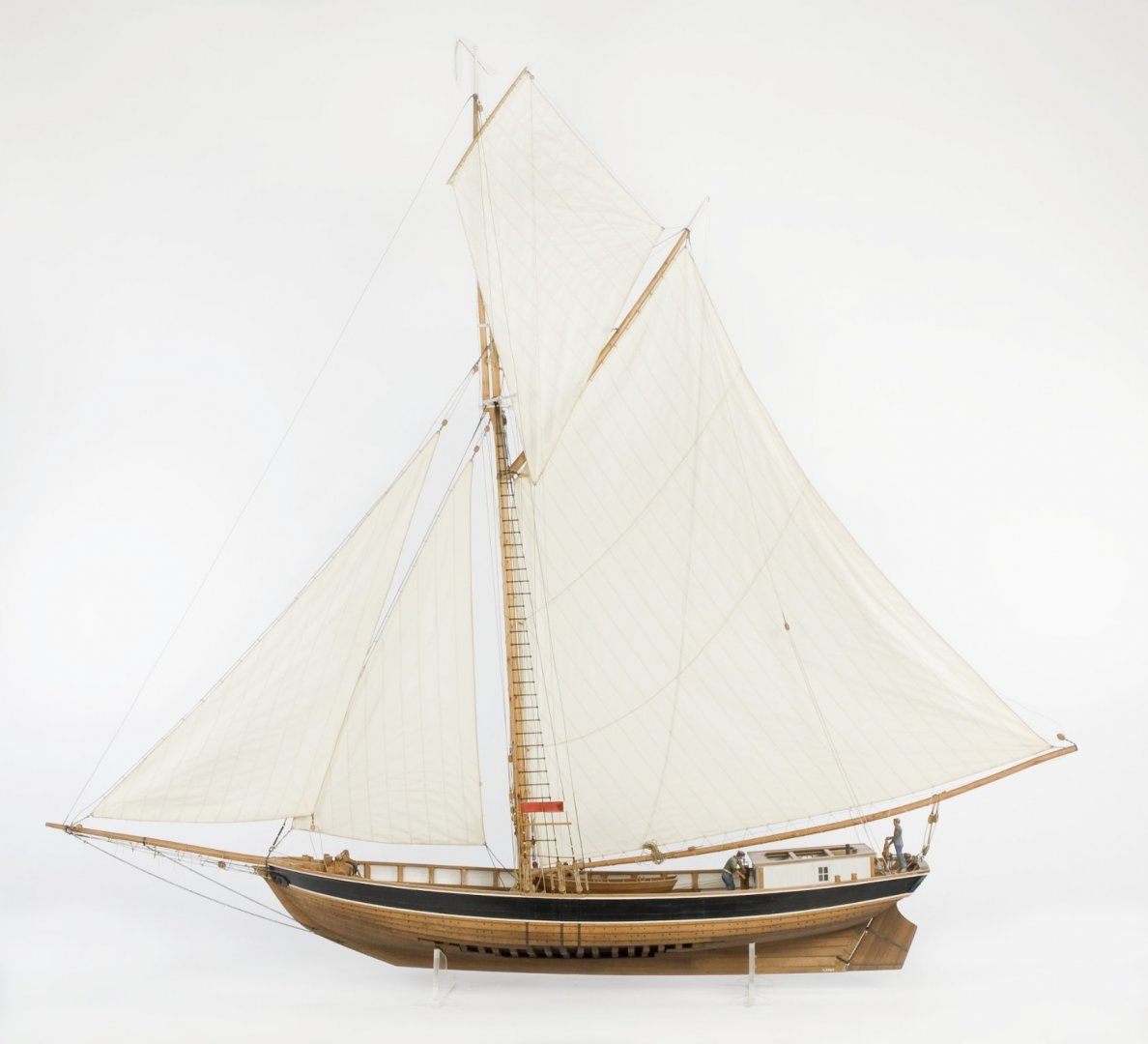

-
Sloop from Roslagen by bolin - FINISHED - 1:50
bolin replied to bolin's topic in - Build logs for subjects built 1851 - 1900
I would be really nice to see you start a build of this little gem yourself 😉. -
Sloop from Roslagen by bolin - FINISHED - 1:50
bolin replied to bolin's topic in - Build logs for subjects built 1851 - 1900
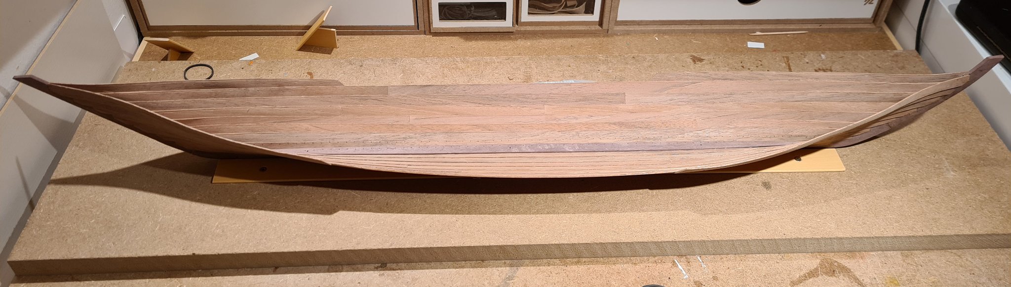
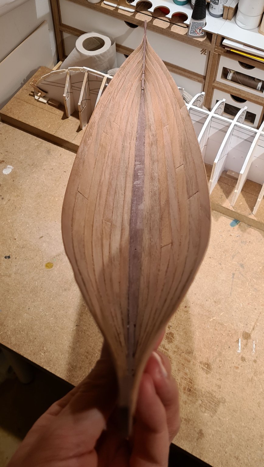
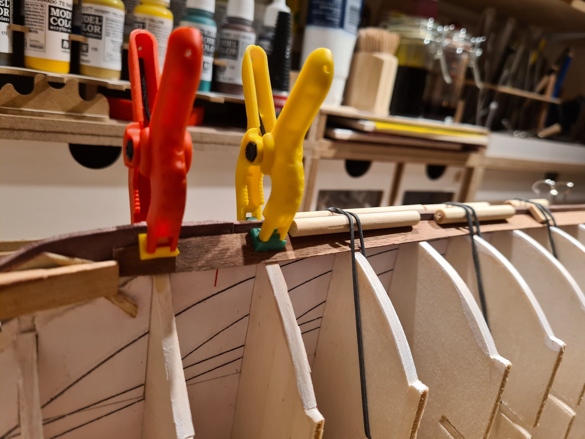
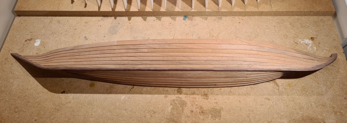
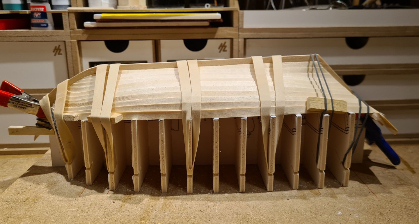
The last clinker strakes are cut, formed, soaked and clamped to the mold for drying. Now there is only gluing it in place, and then its time to lift the hull from the mold and move it to another building slip where the framing can start.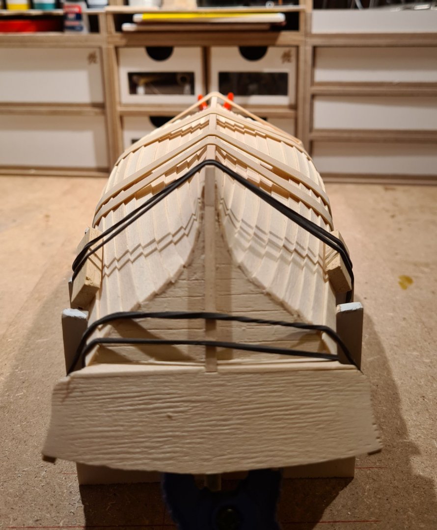
-
Before I started to cut the planks I cut a template from some card stock. This helped me discover that the fairing of the frames closest to the bow and stern was not adequate. When fairing I had not taken into account that the rabbets makes the hull even narrower close to the ends. So I had to remove a bit of the material on the first and last mold frame. I also discovered that the rabbet needed to be a bit lower in the stem to let the plank run correctly. After I had fixed these issues, I cut the first planks. There are very little shaping of the garboard plank. Its 8,5 mm wide along all its length, except for a slight tapering in the ends where it goes into the rabbets. Even so it took some work to get the the planks to the correct length to fit into the rabbets on both ends. When that was done I could soak the planks in hot water and bend it to shape in place. One thing I think I saw, and need to check more, is that the plank seemed to be longer after I had soaked it. I would expect it to swell sideways, but not as much length wise. Maybe I cannot use soaking on walnut? Especially not for such long strips as these (over 50 cm).

- 179 replies
-
- 9
-
-
- longship
- Helga Holm
- (and 1 more)
-
Really nice looking barrels. All of them. I think your father is right. Tying the forestay to the end of the bowsprit puts a lot of strain to where it is attached to the bow.