Jump to content

Rick310

NRG Member
  • Posts

    579
  • Joined

  • Last visited

Everything posted by Rick310

  1. Jared, my intent is to not glue the masts in place , rather wedge them. That will allow me to remove the masts as I work from the mizzen, forward. At least, that’s the plan. I’m also planning to rig the lower masts first, shrouds, Spencer gaffs, ect before installing the topmast. The fly in the ointment is the topsail yard which has to be installed before the topmast cross trees can be installed off the model. This will be an interference when installing the lower yard.and will be vulnerable to breakage! I just don’t know any way around it! I know that there will be plenty of other rigging dilemmas as we both move forward! Keep up the good work!! Rick
  2. Thanks Rob! I am followed your advice to work from the mizzen, forward. I‘be learned a lot from your experience, also from George and Jared! Rick
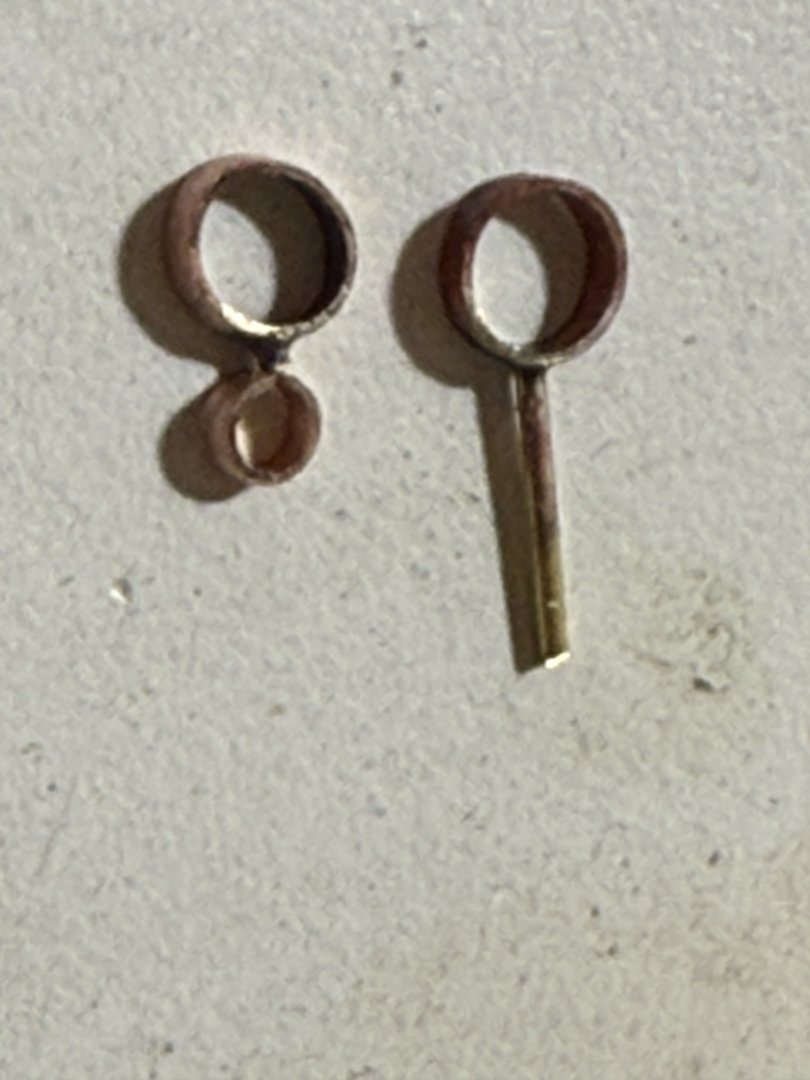
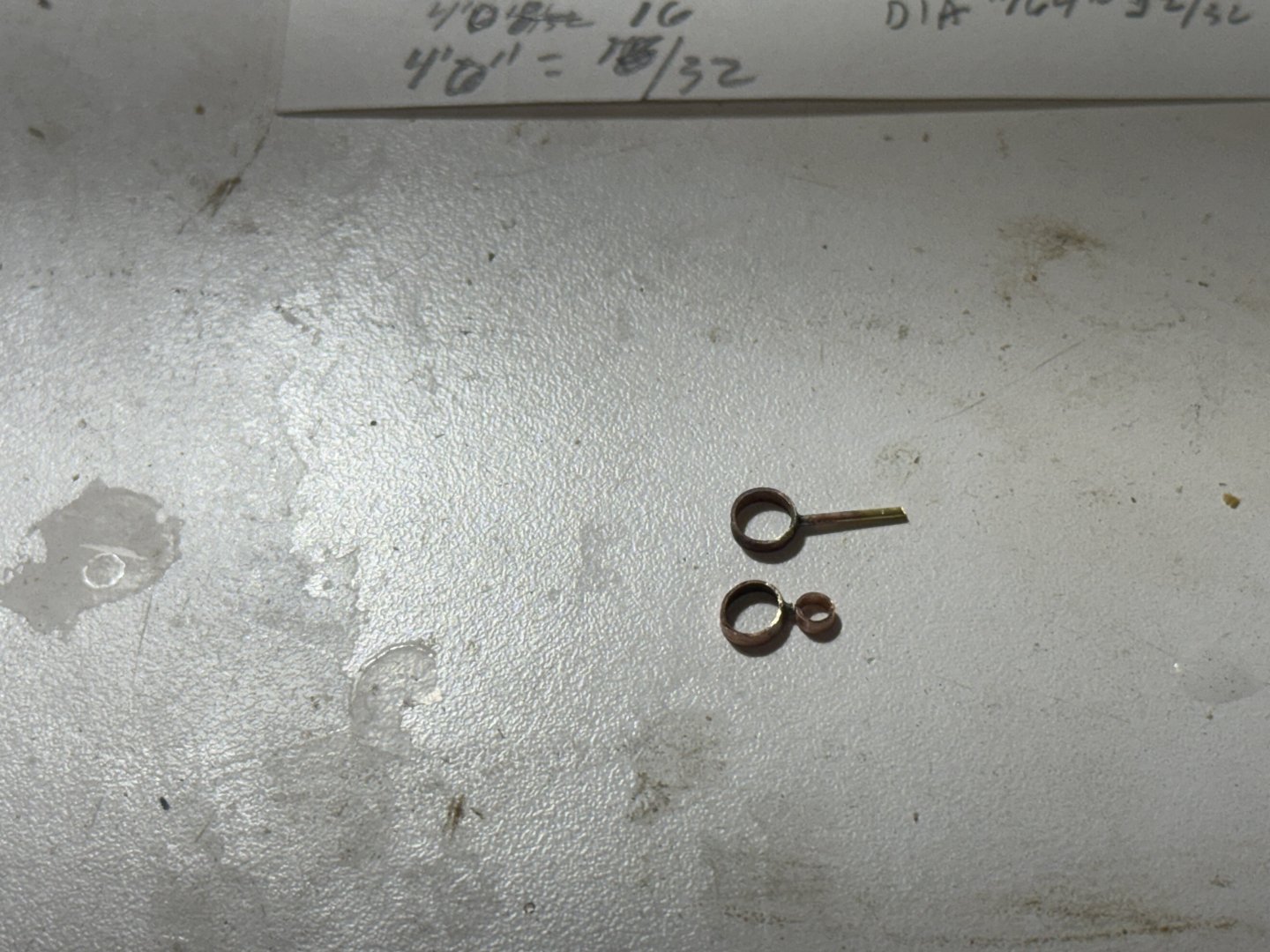
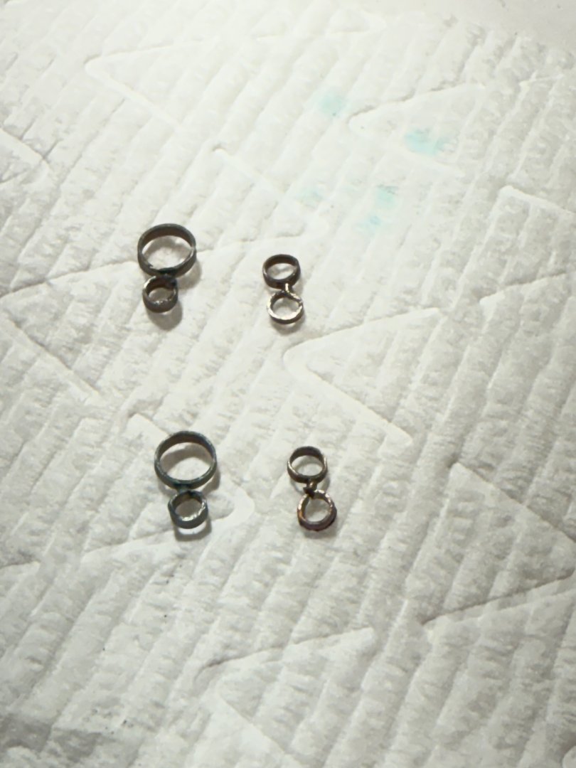
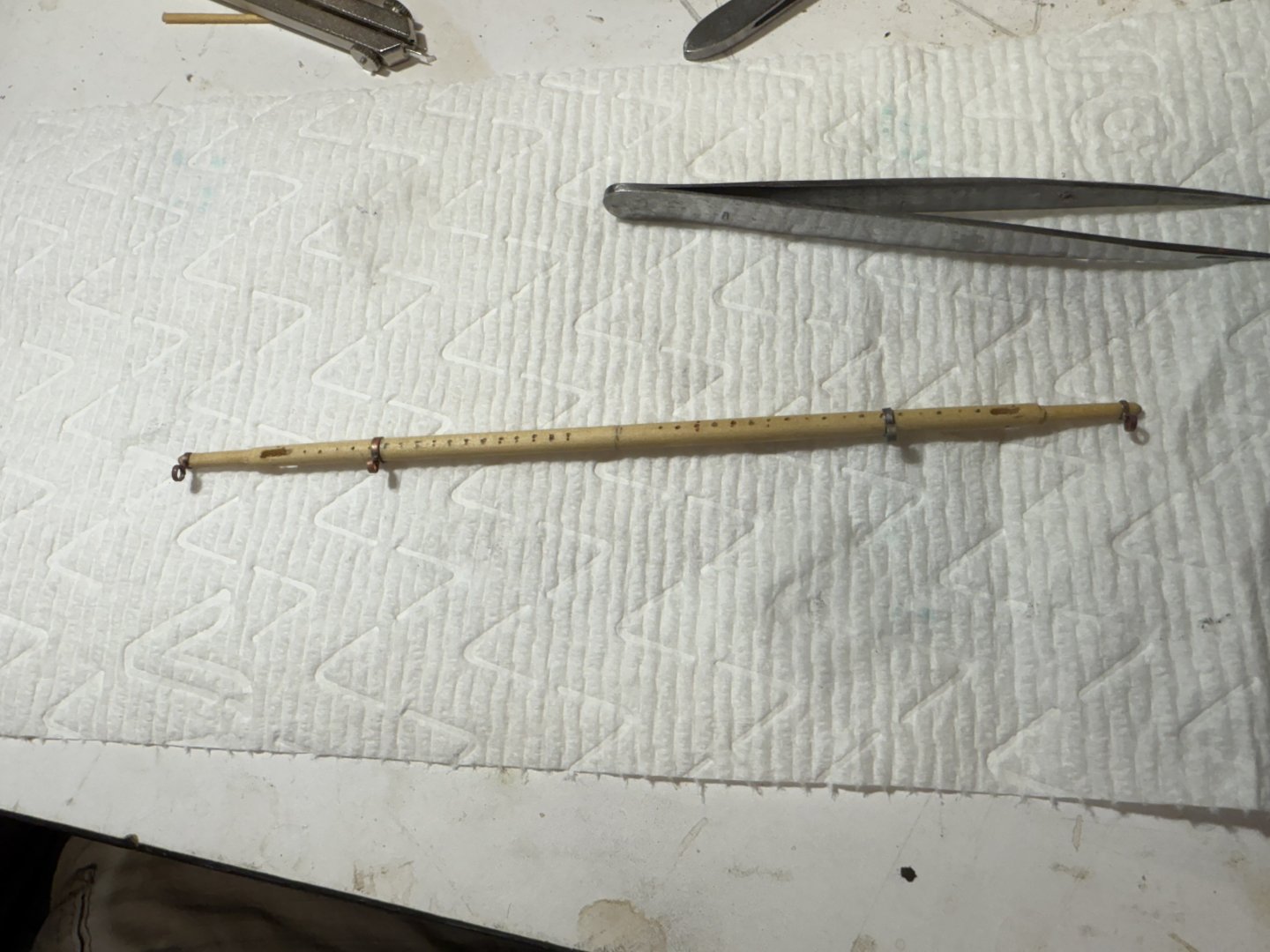
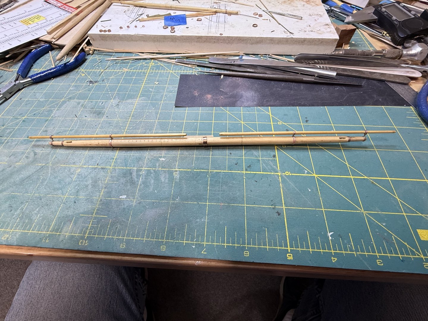
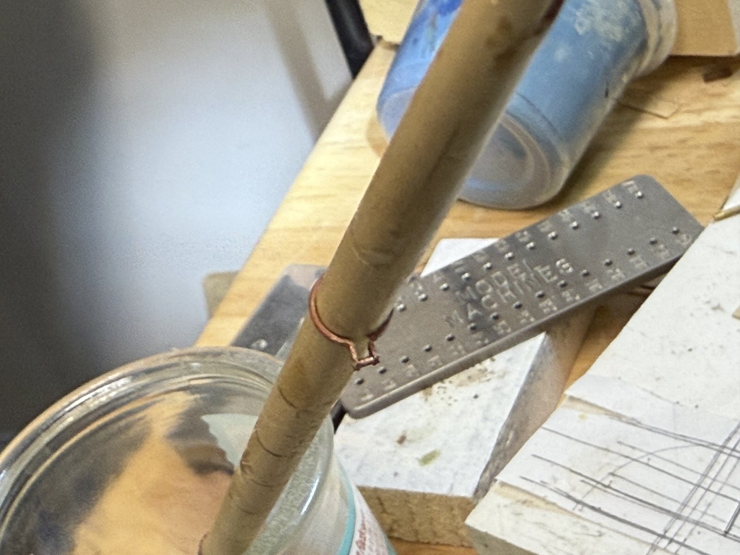
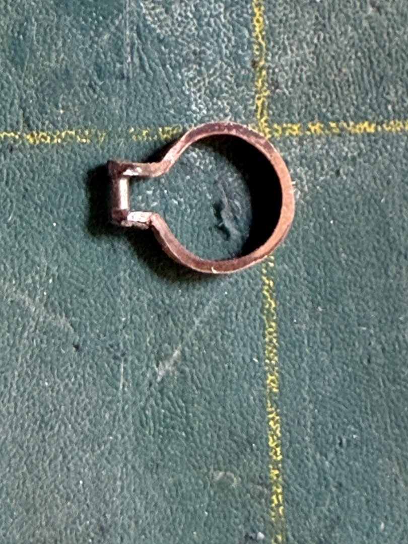
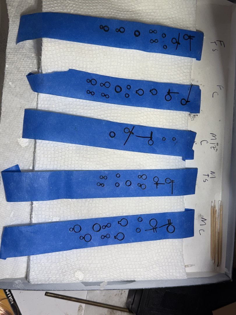
  3. Just a quick update. Finished the main and fore topmasts except for painting and installation the sheaves and fids, which I’ll do after painting. The next item was the fairlead planks. These are .20 inches thick and 3/32 wide. The rest of the planking for the tops is 1/16 inch wide. These were made from boxwood and stained with Ipswich pine as were the topmasts. These were fiddley items to make which took a lot of time and constant re measuring. Both planks for each top were glued together and glued to a piece of wood that was then placed in the milling machine. They were released by soaking in water. Not perfect but serviceable. Next up were the caps. Again, much time and constant checking to be sure the topmast would be parallel. These were then shaped and the straps soldered from 3/64 inch wide brass strips. Still need to bevel the caps. The holes for the tenion were cut with an undersized drill and chiseled out to the correct size. One of the difficult things with the solid hull kit is that there are no lazer cut parts . Each part has to be individually made which takes a considerable amount of time and effort. .
  4. Rich, Rob, after reading your comments earlier today, I sat down to read the September issue of the NRG. And lo and behold the editorial talks about Chapelle and his reluctance to divulge his sources for the drawing he did! The article questions if he really knew the layout of the ships he drew and what does that mean going forward! Are we just perpetuating errors that we have conveniently assumed were correct especially if they came from Chapelle? WOW!! Rick
  5. Bingo!!! Rob and Rich, I totally agree! Everyone has relied on Chapelle as gospel. Who knows what he knew. Is the deck layout on the Challenge model based loosely on a description with generic items such as the winch, capstans. Wc, added because all ships would have had this equipment with no real evidence that this was specific to the Challenge? Including the design of the forecastle. My understanding is that the genus of both McKay and Webb, was the design of the body plans, specifically that part from the planksheer down as that would determine all the qualities of that particular ship, speed, cargo capacity, handling characteristics, ect. Everything above was somewhat generic to all ships. He certainly would have designed the forecastle and aft cabin. If I’m not mistaken, Mc Kay left the rigging up to Her captain Edward Nickolas on the Flying Fish. I’m not sure how involved McKay or Webb would have been with the finish carpenters when it came to deciding the moldings, carved knees, cabin interiors ect.He probably trusted them and left it up to them to do a good job. Makes me wonder how many clipper ship models that we see are just generic models that someone named a particular ship? Rick
  6. Rob, I have to agree with you on that. However, Ben Langford states that one of his references was the Challenge model in the Smithsonian. The plans for that model where developed by Howard Chapelle, and it has the WC as depicted on the Flying Fish. I have 2 very old photos of the model. Rob, I’m not disagreeing with you, but there is a precedent for that location on a contemporary American clipper ( May 1851) Rick
  7. Thanks Keith, I’m going to file that away for use at another time! Rick
  8. ClipperFan, I found the article in the NRG journal written by Ben Lankford about how he developed the plans for the Flying Fish. It’s September, 1980, #3. It is a fascinating read! Not much is said about the WC/companionway, but he deliberately chose an older style windlass as more appropriate. This is the same style seen on the model of Webb’s clipper Challenge at the Smithsonian in DC.
  9. Just reread your blog, you are doing a really nice job!! I especially like the way the planking on the forecastle came out, the nibs look great, really stands out! Keep up the great work!! Rick
  10. Keith, that would s one beautiful hull! earlier, I believe you use sawdust and white glue to repair defects. Does varnish work better? Rick
  11. Rich, I purchased the painting from a very good friend of mine who had been a marine antique dealer for 55 years. He purchased the painting at an auction in Maine (Julia’s, no longer in business) It was as originally mid-identified as a York. Rick
  12. Rich, interestingly the Golden Rule was built in Newcastle Maine which is separated from Damariscotta by a short bridge over the Damariscotta river. There is a harbor in Damariscotta and you can look across the harbor to a small peninsula of land on the Newcastle side which is the site of the Hitchcock shipyard. There is also a display commemorating Fitz Hugh Lane’s painting of the Golden Rule. Rick
  13. Thank you for your excellent explanation on how you made the raised panels! I would never have thought of that and yours came out beautifully! Rick
  14. Rob, that is an excellent point! Did not think of that! In one of the NRG journals, 1980 I think, Ben Langford gives an explanation for why he and Erik Romberg choose to design the WC/companionway the way they did. As I recall, it was more of a guess than any thing else, I could be wrong, but I seem to remember that they were somewhat mystified themselves. I have that copy and will look it up. Rich, if I had to do it over, I would have extended the stem even more per your suggestion. I previously believed that the bow in the Buttersworth’s painting was a bit of exaggerated. Now convinced that it is probably accurate! Rick
  15. Just a magnificent model Keith!! What a fun project!! Incredibly well done!! Rick
  16. Rich, The captain of the Flying Fish was Edward Nockels until she was wrecked leaving Foochow. She was subsequently repaired/rebuilt at whampoa(?), sold to Manila firm and lost in the South China Sea. Thwre is another shi, a brig? Also named the Flying Fish. This rail probably came from this other ship. Rick
  17. Rich, there is a beautiful painting of the Golden Rule by Fitz Hugh Lane. This is the info I could find on the Golden Rule. Rick
  18. Rich, the Golden Rule was built in Newcastle - Damariscotta, Maine, by Col. Hitchcock in 1854. The painting is attributed to Charles Ogily, a Liverpool artist, known for his paintings of pilot boats.
  19. Rob, ClipperFan, Jared, Thank you for your kind words! Still trying to get over the jet lag and get caught up with the yard work ect. The water closet is in front of the companionway entry on the FF plans, both contained in one structure. Water closets on either side of the forecastle seems to be a common place to locate them per Cutty Sark and other contemporary paintings.( see photo of painting of the clipper ship Golden Rule). Ben Langford chose to make the water closet larger with the companionway steps leading below on the aft side . This seems to meet the description by Duncan Mc Lean although it is all conjecture. Interestingly, the Buttersworth painting shows no evidence of them. Omitted or hidden by the rail? Or a forecastle similar to your beautiful design? The anchor windlass you have for Stag Hound seems to me to be a latter and more modern version. Do you have any information when this specific design was produced? ClipperFan, the larger lubber hole on a he CS was all metal, this would be stronger than wood. I don’t see how you could cut the middle cross tree and retain the strength on just 2 full length cross trees. Clipperfan and Rob, thanks for your input. I would love to be able to talk to Donald McKay and see if this model and the plans are accurate to the actual vessel. Both of you have brought up interesting points and another way to interpret the written description! Keep up the great work! Rick Rob, I knew you had a long career in Dentistry, which helps to explain your remarkable modeling skills! Rick
  20. Jared, nice recovery on repairing your mast. I too had to repair the top of my mizzen mast , which I snapped off while drilling the holes for the skysail halyard. This seems to be a common theme among us model ship builders! I can only imagine what’s going to happen with the spanker boom and jib boom! I’m already thinking about affixing some kind of a guard for both booms, otherwise it is a certainty that I will snap them off as well!! You continue to do a great job and you are progressing nicely! Rick
  21. Well, September was quite a month. Finally retired after 40 years as an Endodontist (root canal specialist) and 45 years as a dentist! The admiral and I celebrated by taking a Viking Meditation cruise in between clearing out the office and preparing for our daughter’s wedding in 2 weeks. I was able to get a little time in the shop, and finished the trestle trees and cross trees with the curved rims for both the main and fore masts. These were made same as for the mizzen in an earlier post per EdT, modified for my convenience. They still need to be painted, planked and fitted out. Both the main and fore topmast were also made prior to the cross trees to insure an accurate fit and proper spacing. Note that none of the mast are permanent installed yet. My intent is to shim them and not glue them in place to make it easier should repairs ever need to be made.
×
×
  • Create New...