Rick310
-
Posts
833 -
Joined
-
Last visited
Content Type
Profiles
Forums
Gallery
Events
Everything posted by Rick310
-
You’re doing a really nice job!! Looks great!! Rick
-
Hull looks great Rob!! Rick
-
I disagree. Europe may have been designing ships on paper at that time. I don’t know much about European ship building techniques, however, I would like you to show me an American ship plan from the mid 1850’s from which that ship was built, Any plans on paper originated from the half models/lofting floor.
-
I really don’t like to get involved in these kinds of discussions. However, I think I need to add to this discussion. Ships were not designed on paper until the late 1800s or early 1900s. Half models were the way ships were designed even up through the 1920s and the 30s. There is plenty of literature and one only needs to visit the Maine Maritime Museum. They have a display on how half models were used to layout the pattern for the frames on the lofting Floor. The way it worked as I understand that is that all the principles involved in the ship, such as the principle investors, shipyard owner, and captain got together and with a master model builder would decide what qualities they wanted in a ship’s sailing characteristics, such as cargo capacity sail handling and speed. The model maker would then put lifts pegged together and then he would carve these from the plank shear down into the form that met the desires of the principles. When everybody agreed that this was what they wanted, the half model was sent to the lofting barn where measurements were taken off of the half model and drawn on the floor of the lofting building at full size from the half model. Wooden battens were shaped into the shape of the full sized frames that were then sent to the sawmill to cut out the pieces of the frames.At no point was he designed drawn out on paper. These half models were known as builders models as they were the actual model the ship was built from. Go to any Maritime Museum specifically the Maine Maritime Museum, and they have dozens of builders half models. Cornilius’s model would not have been the actual half model of Staghound, as that model was used for lifting the frames. Although not the original builder’s model, it is without question, very accurate. Clipperfan, you are absolutely correct! Rick
-
Coming along nicely! Rick
-
That has been great advice Rob! Can’t imagine trying to rig the FF any other way and not break something, which I still manage to do occasionally! Rick
- 360 replies
-
- 1
-

-
- Flying Fish
- Model Shipways
- (and 1 more)
-
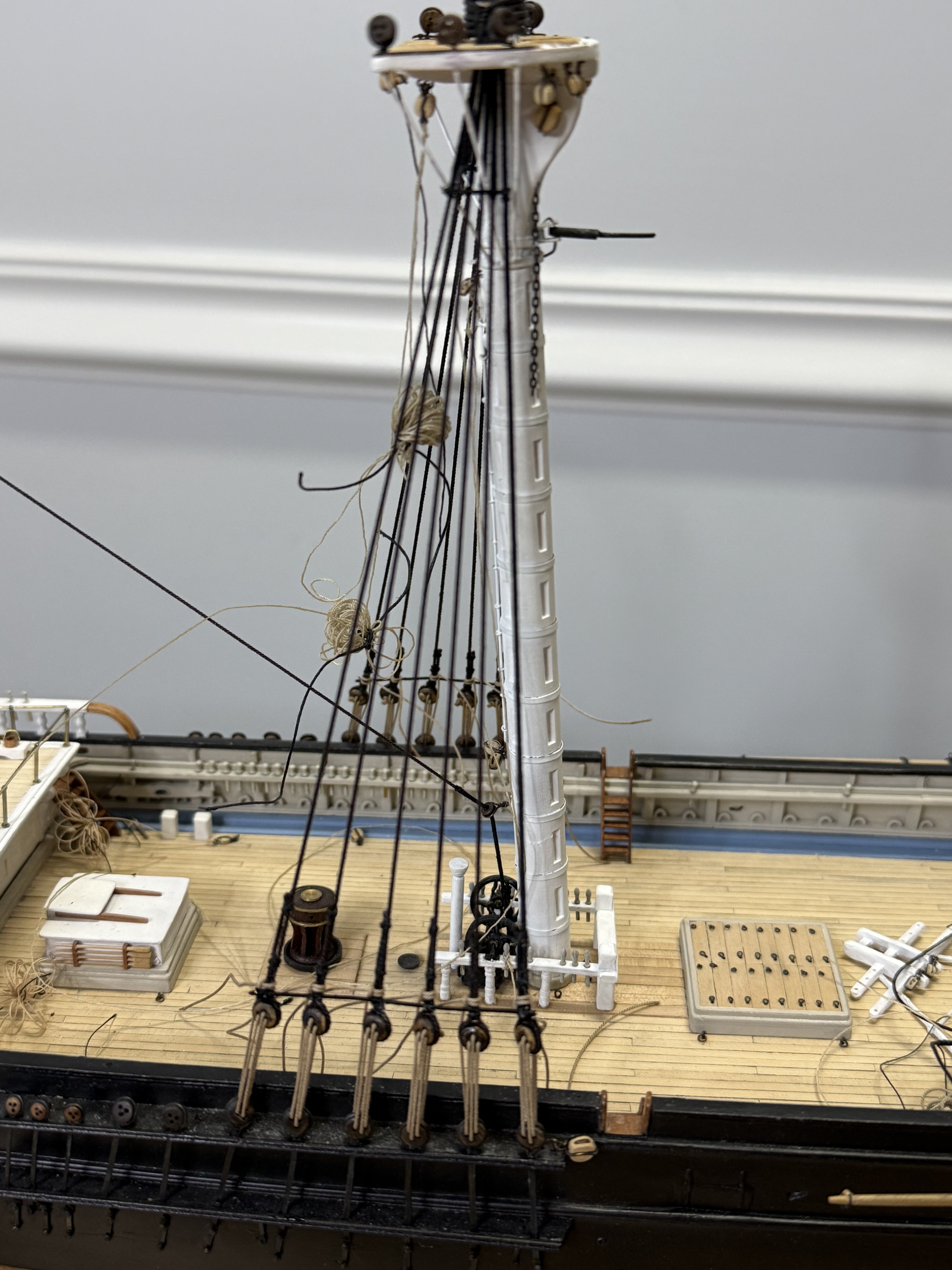
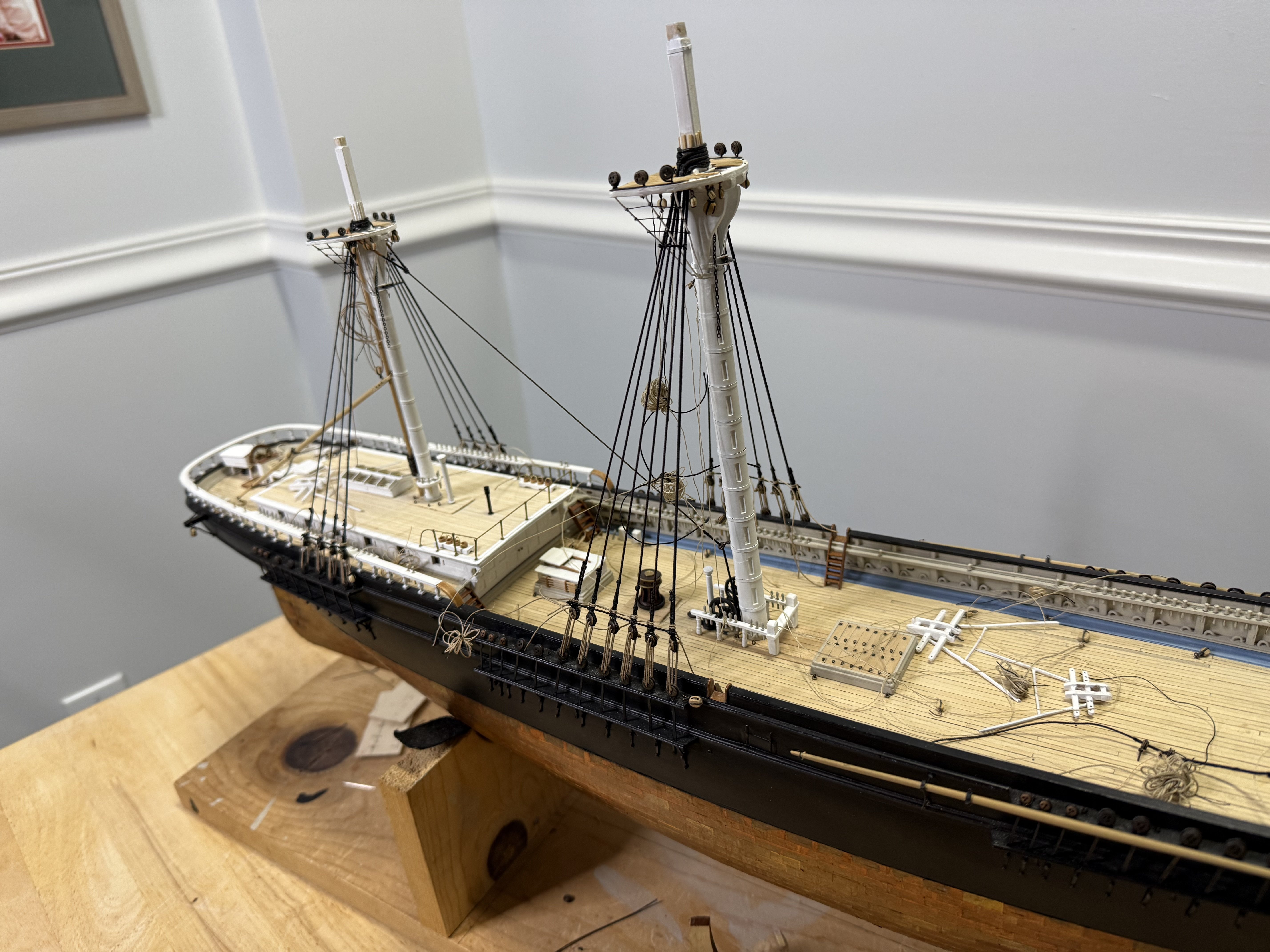
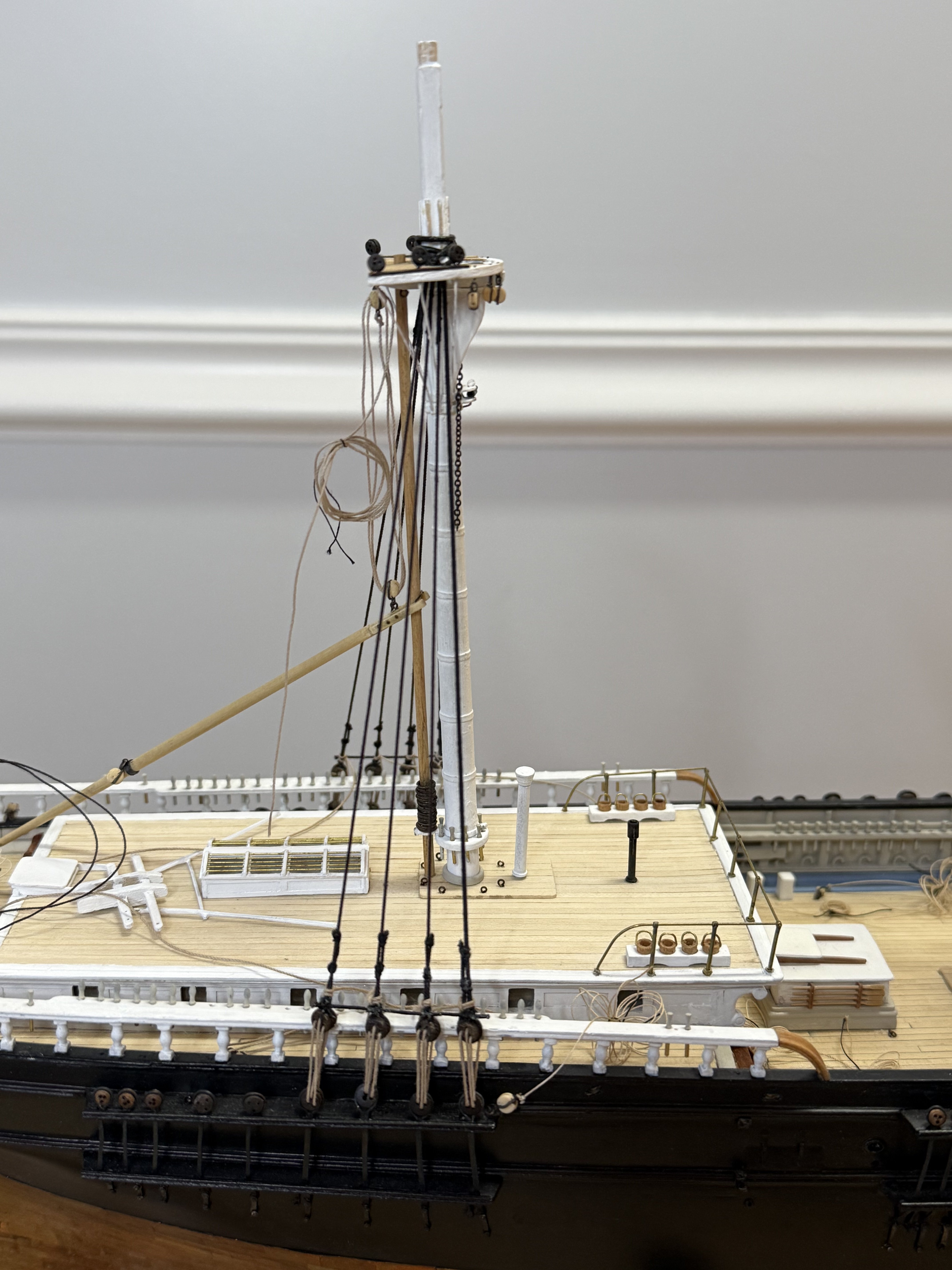
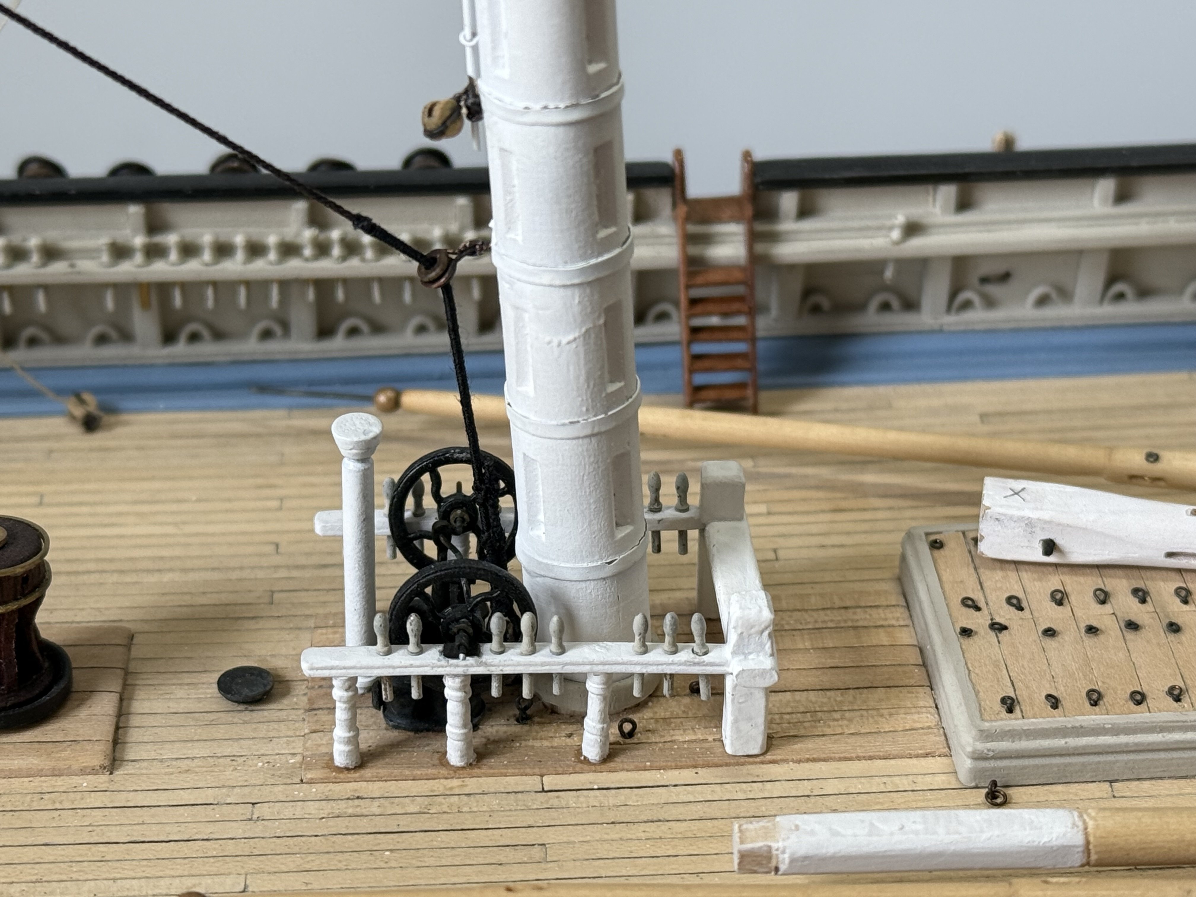
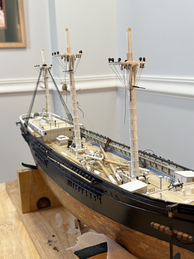
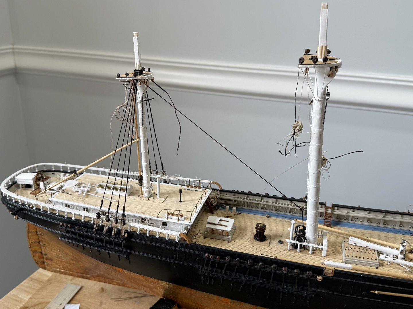
Brief update. Finished the main shrouds, same as mizzen with serving and parcelling. It was at this time I realized I needed to rig the main yard lift tackles. Access to the mizzen and fore mast is straightforward, as I have yet to place the fore cabin. but the main mast is severely restricted. Should have rigged them prior to stepping the main mast. After strapping 3/32 single blocks with 26ga copper wire and rigging the tackles with .008 line, I was fortunate to get the lower blocks into the eyebolts next to the mast by working under the fife rail. Would have been much easier before the masts and shrouds placed! Next up are the other lift tackles and the main stay. Working from aft, forward has been much easier than forwards aft!! Thanks Rob and George for the great suggestion!!


- 360 replies
-
- 7
-
-
- Flying Fish
- Model Shipways
- (and 1 more)
-
Very nice Rob! You can already see the beautiful contours of her hull! Rick
-
WOW!! Beautiful!! Rick
-
Looks really good!! Nice job!! Rick
-
Better to just correct the mistake than to have to live with it, always asking yourself why you didn’t get it right when you had the chance! Don’t ask how I know! Rick
-
Very nice!! Rick
-
Very interesting build! Rick
-
Looks really great George!! Well done!! Rick
-
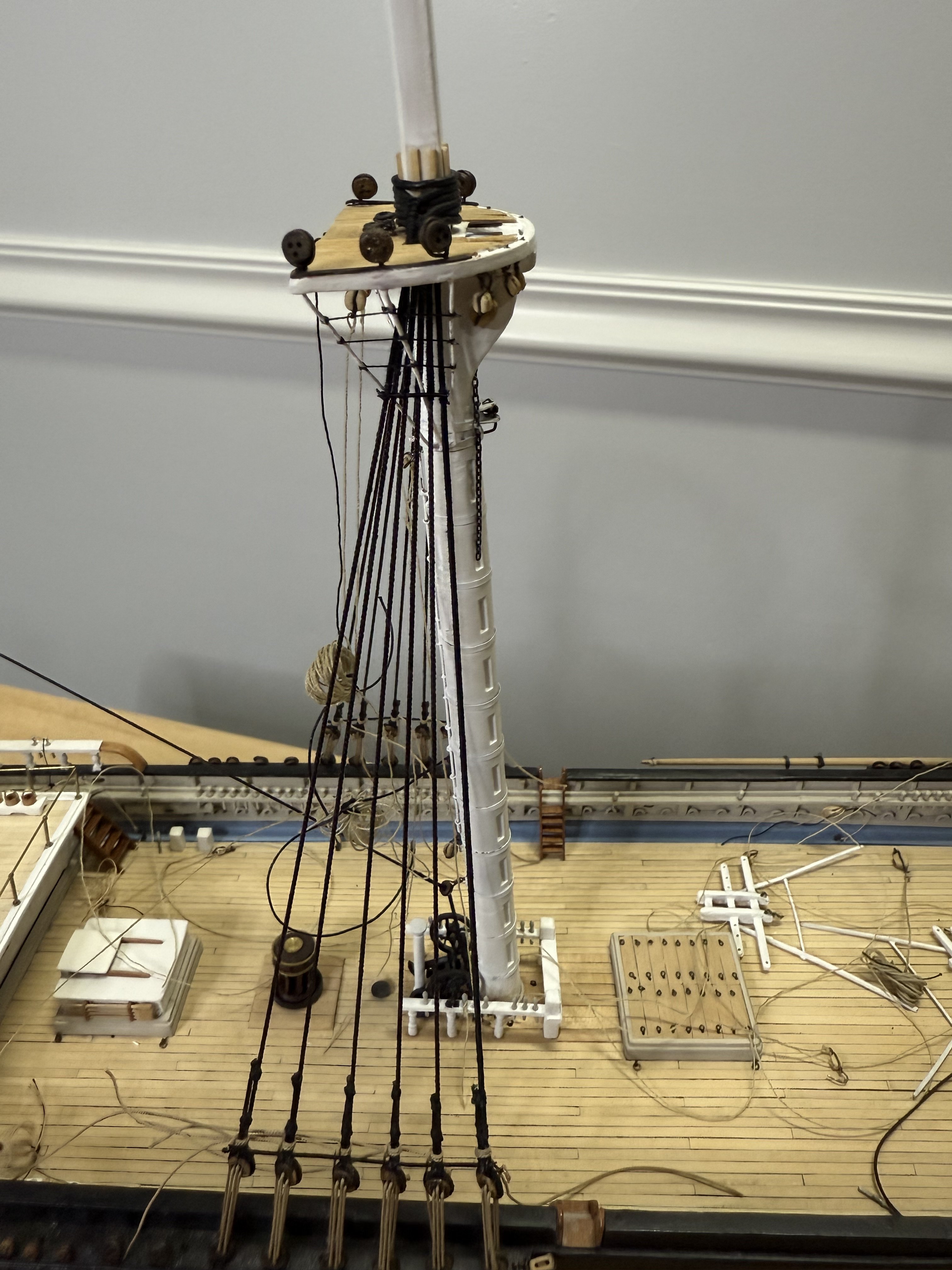
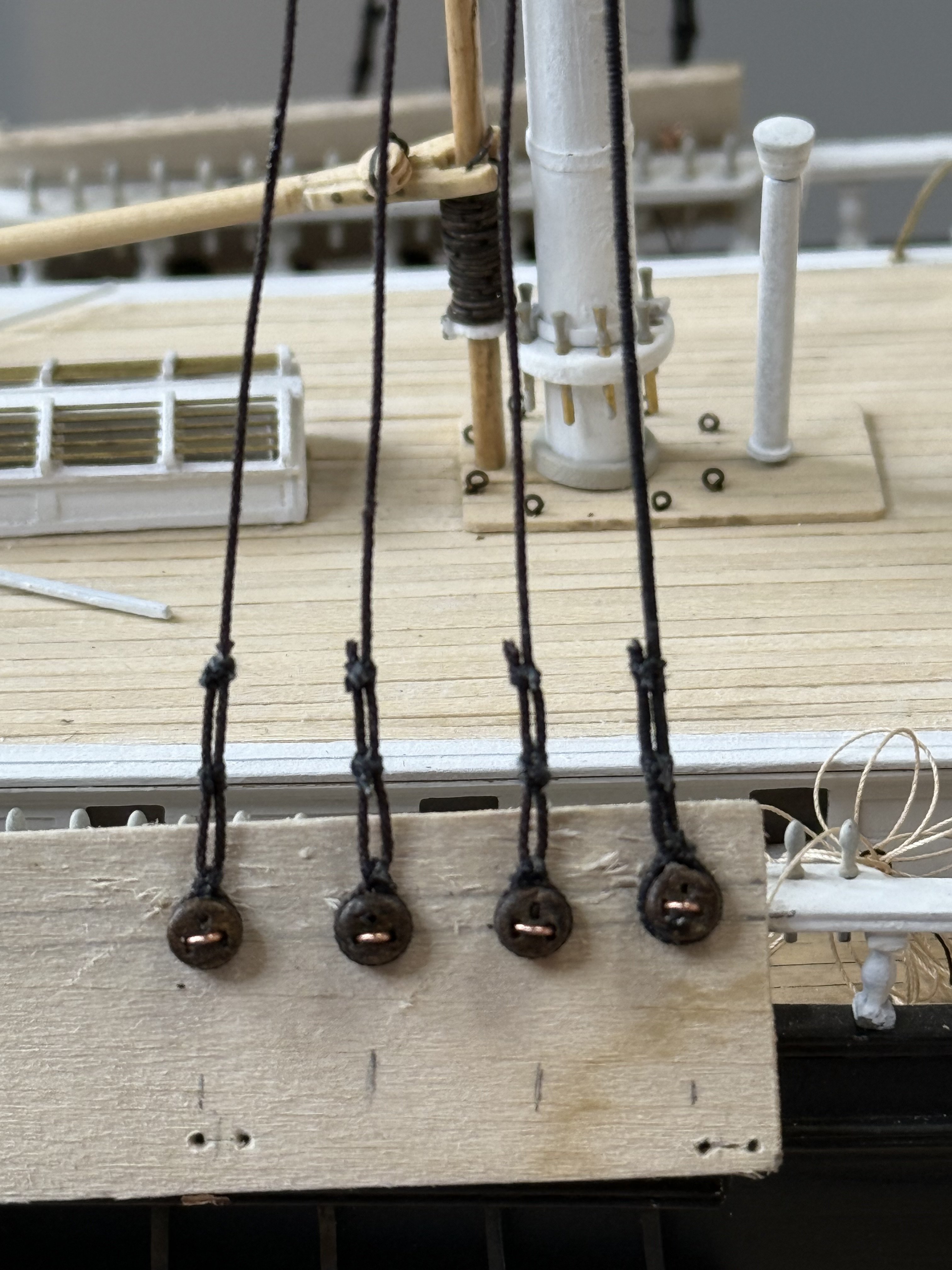
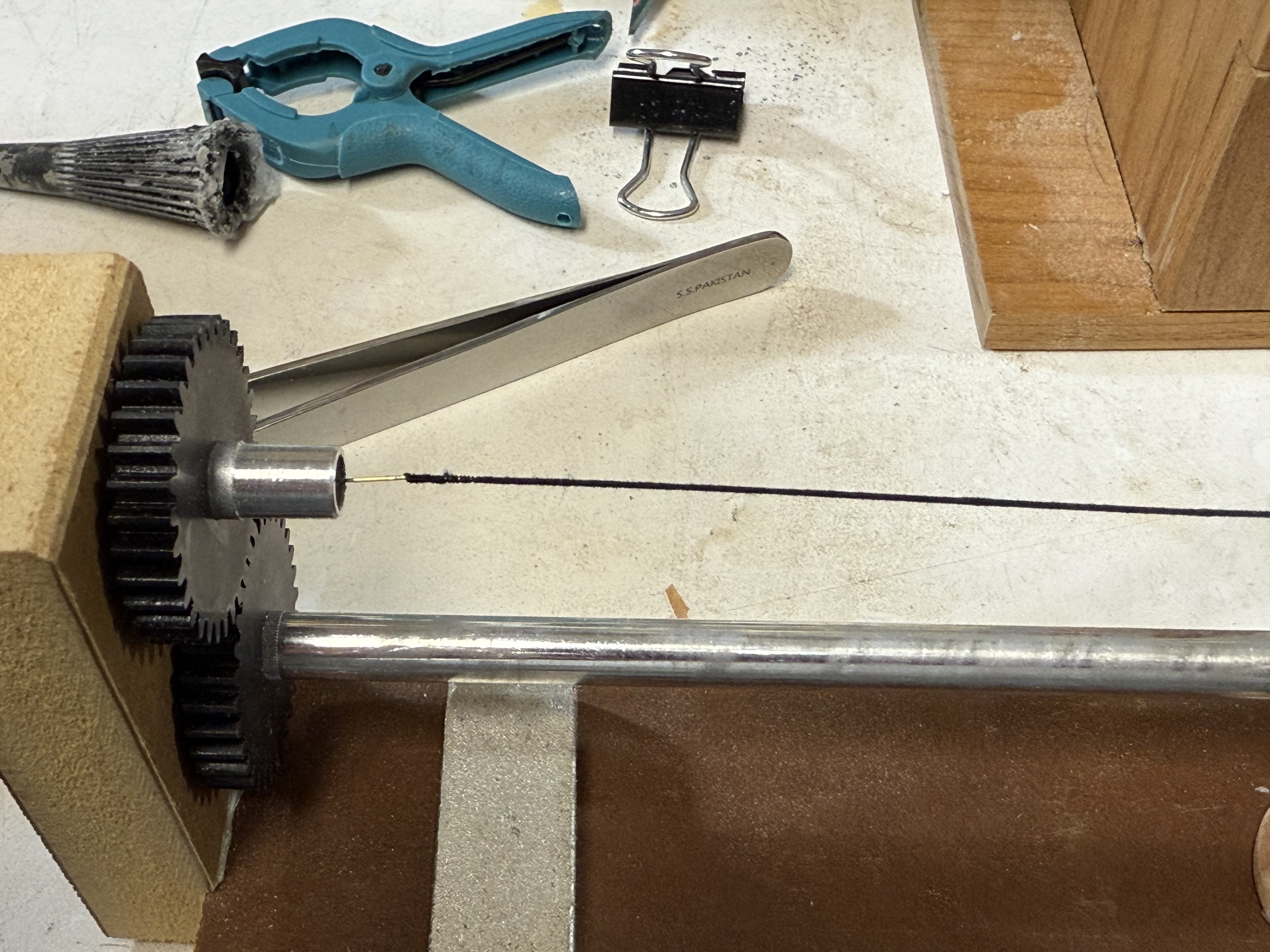
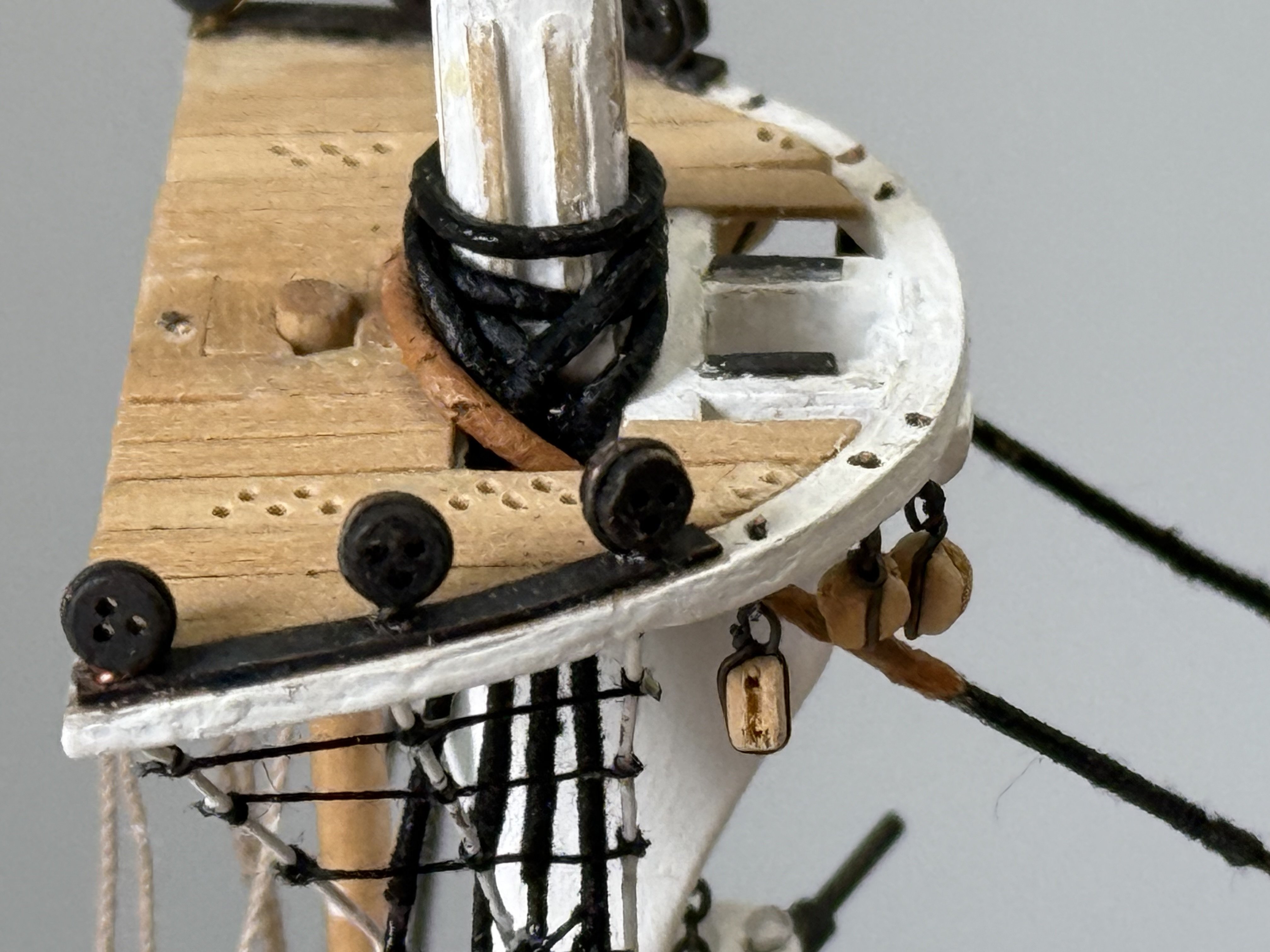
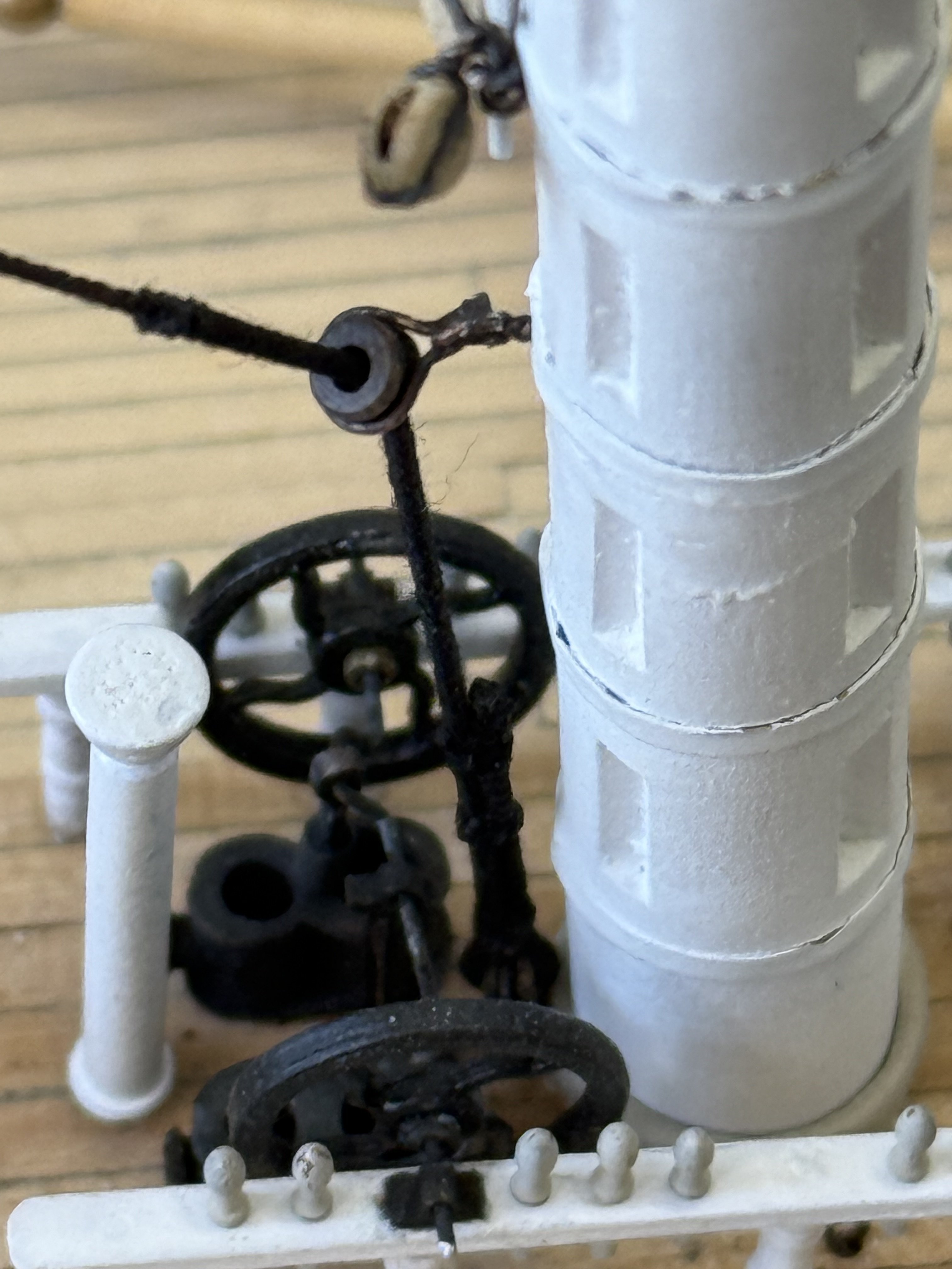
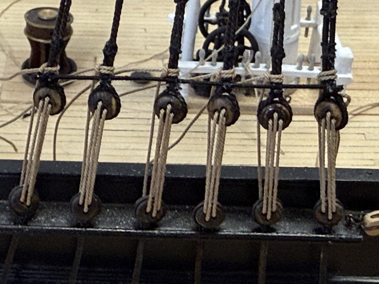
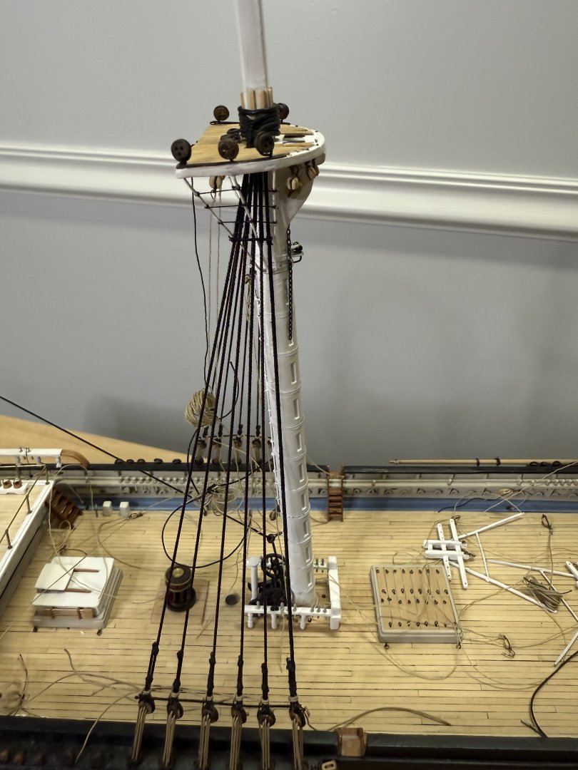
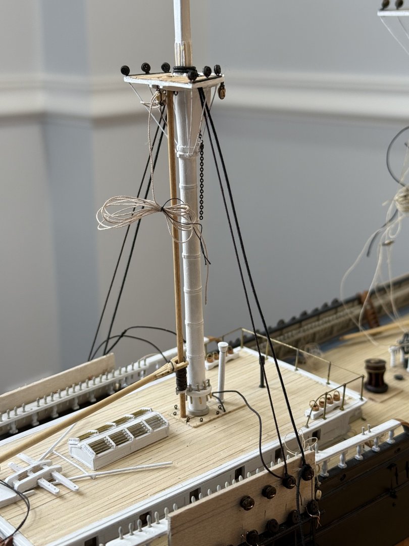
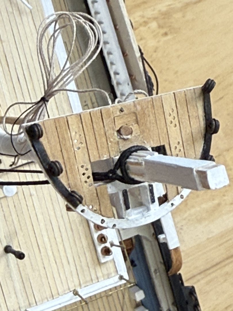
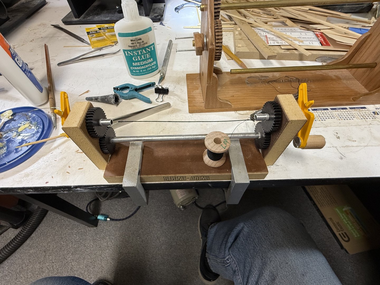
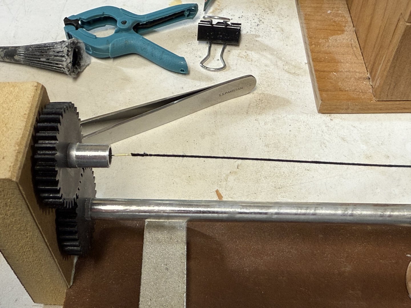
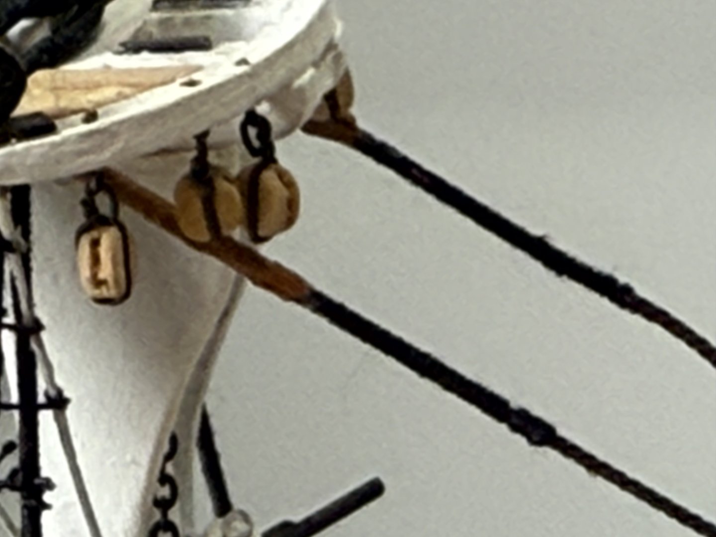
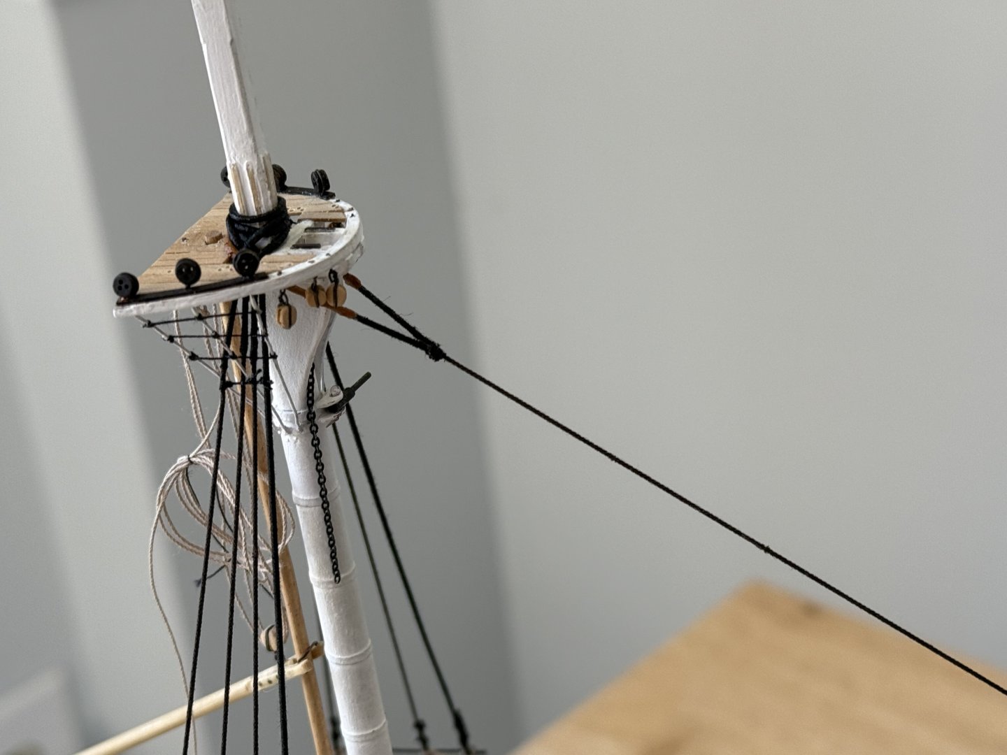
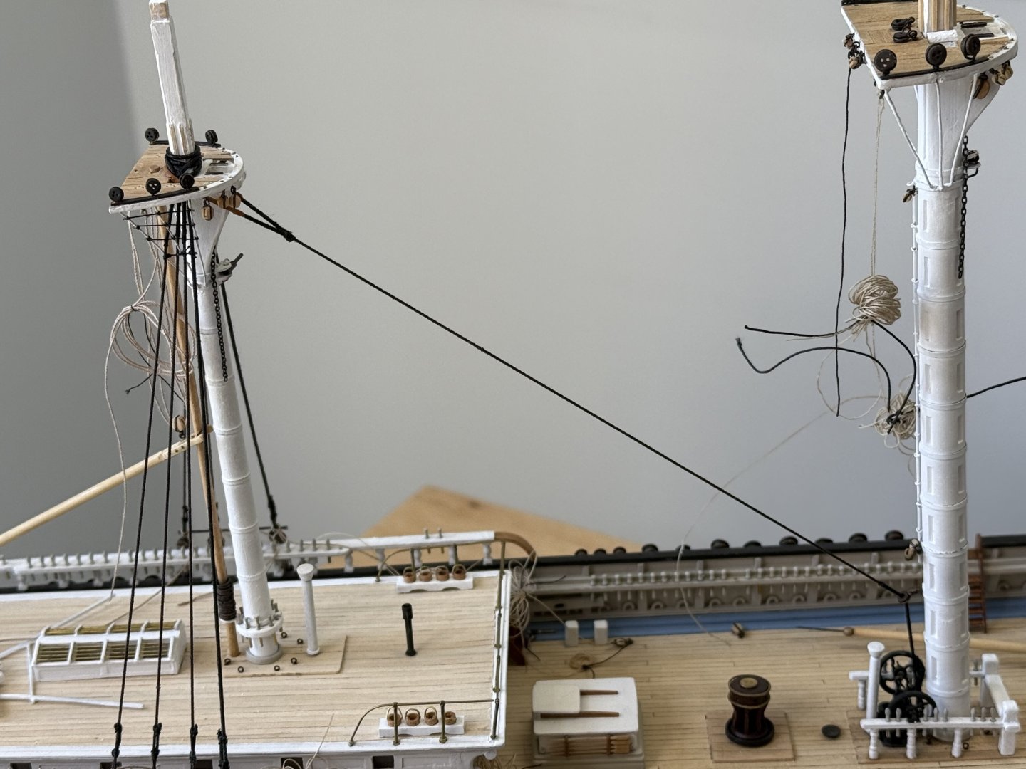
Started rigging the mizzen mast. I decided to use .025 diameter line from Syren. This is a bit undersized for the shrouds but I plan to serve the line, which will bring the served portion to approximately the correct diameter. The thread I am using to serve is approximately .004 inch diameter from Bluejacket. I will also use this thread for the rat lines. This is a bit too large but anything smaller I fear will be too difficult to work with. Several years ago I purchased a serving machine from Syren, forgetting that 3 decades ago I purchased one from Model Shipways(?). It ended up fortuitous as the one from Syren works great for the shrouds and the other one works well for serving the 28 gauge brass wire sheer poles. Serving extends from the futtock shrouds to the upper deadeyes on the first ( forward) shroud. The shrouds were served and parceled per EdT and the Young America. Serving the shrouds was not difficult and actually enjoyable as long as I gave it my full attention. The parceling was silk span and painted black with acrylic paint. I made a jig to hold the upper deadeyes, again, as described by EdT. This seemed to work well until I went to lace the deadeyes and the last 2 were too long. All three seizings had already been tied and when I tried to cut them to adjust the length between the upper and lower deadeyes, I damaged the last 2 shrouds on the port side and had to replace them. I recalled from Nic at Bluejacket that to shorten the length, the shrouds can be twisted to shorten, or untwisted to lengthen This is what I did on the other shrouds. The downside is that the upper deadeyes want to untwist and getting them to face forward with the sheer pole was difficult and challenging. The result of s not as good as I would have liked but I’m going with it. One difficulty was deciding how long to make the short end of the shroud. No where could I find any reference for the length, so I arbitrarily went with 12/32 inch or 3 scale feet. All seizing were placed using a needle which worked well. Again, not as good as I had hoped with the results but hopefully they won’t be that noticeable and I will get better moving forward. Sheer poles were added at the junction with the futtock shrouds and at the top of the upper deadeyes. This was the only one I served. Later, I will add the staves of 28 gauge brass wire. Not sure if rigid staves are appropriate for 1851, but they will help hold the shrouds in place when I tie on the rat lines. Starting with the mizzen mast was a huge advantage when I placed the mizzen stay! After careful measuring and serving, the forward end of the stay was past through the bullseye and seized back on itself. This was done on the bench. The fairlead that attaches to the main mast was previously slipped on. The bullseye was then glued into place, the main mast inserted, and the fairlead glued to the main mast. The other end was taken through the lubber’s hole, around the mast head, and seized to itself where the serving meets. This seizing came out much better. Silk span was wrapped around the serving at the mast head and painted brown to simulate leather. Additionally, the mizzen spencer’s throat halyards was rigged while it was still accessible. I left it loose for now. Finally, I made the in haul/out hauls for both the main and fore spencer booms. These were attached together with bowline knots and threaded through the blocks at the Spencer gooseneck. .


- 360 replies
-
- 6
-
-
- Flying Fish
- Model Shipways
- (and 1 more)
-
Flying Fish is looking really good Jared! What a difference with the yards on her mizzen! Rick
- 431 replies
-
- 1
-

-
- Flying Fish
- Model Shipways
- (and 2 more)
-
WOW!!! Beautiful work!! Rick
-
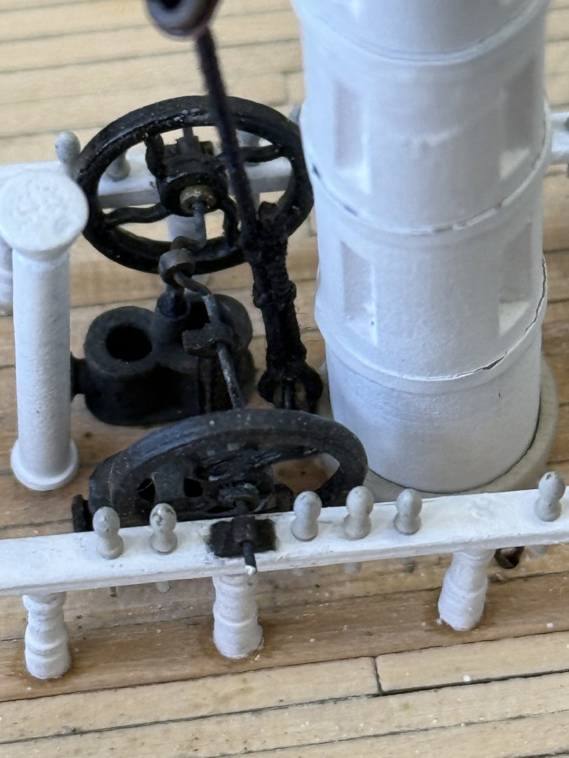
Beautiful job Keith! Lula seems perfectly matched to the piledriver! Best wishes and prayers for a quick recovery! Rick
- 732 replies
-
- 3
-
-
-
- Lula
- sternwheeler
- (and 1 more)
-
Amazing!! Rick
-
You’re doing a great job George!! Rick