Egilman
-
Posts
4,375 -
Joined
-
Last visited
Content Type
Profiles
Forums
Gallery
Events
Everything posted by Egilman
-

kit review V8 Engine BUILD REVIEW (TECHING) - EngineDIY
Egilman replied to James H's topic in Non ship-related reviews
The technology of DOHC 4-V (what they call it today) originally came out in 1911 with the 7.7L Peugeot French grand prix racers... Traces it's lineage from there through Miller's engines to Offenhauser's engines to Fords DOHC 427's to Cosworth then the Porshe/BMW engines to finally the Japanese versions they are running today.... Nothing special and nothing secret about it... Smokey Yunick said it best "...the quickest way to get more power, more cubic inches",... But what he was really saying is put more air/fuel mixture into the combustion chamber... Puegeot came to that conclusion 30 years before Smokey was even born.... -
Thanks Craig, and yes he is... He very aptly shows what can be done out of the box with this kit... I think it should be held as the best new race car kit of 2024.... An easy builder of a stunning model from a great company.... Why a great company you ask? I received replacement parts in the mail yesterday, Parts 58 & 59 Brake backing plates.... They were completely unannounced to me so I checked the kits parts... Those two parts in the kit were slightly short shotted, so finely that I didn't even notice in my inspection of the parts for the review... (and to be completely honest it would never be seen when the build was finished) It didn't matter, they replaced them on their own dime without even asking.... That's the kind of customer service you want in a model company.... Top Notch.... I wouldn't hesitate to buy from them again... (in fact I plan on doing just that in the future)
-
Most people remember it as an amphibian with landing gear, the -5 and later models of this wonderful airplane, they forget it's roots were as a flying boat... Many of which served well into WWII....
-
Keeping my head in the game.....
Egilman replied to Egilman's topic in 3D-Printing and Laser-Cutting.
And another short update.... Front firewall, progress report... Front... Only about halfway there on the engine side, I will probably have to wait for the clutch pedal creation to cut the slot for it in the firewall.. Current state of Cockpit side... What your looking at is the wooden foundation of the steering gears, yes, they are built up wood blocks with holes cut thru them to reach the fixture supporting the gears themselves... The wood forms the inner layers between the metal firewall and cast gear fixture... About to start designing the side walls and braces, they need to be done now cause the angle of the steering gears needs to be fixed..... Also, the sidewalls are different from left side to right side... (today, they would be identical mirrors of each other, nothing easy about this thing).... Anyway I haven't left, I'm still here plugging away... Onwards...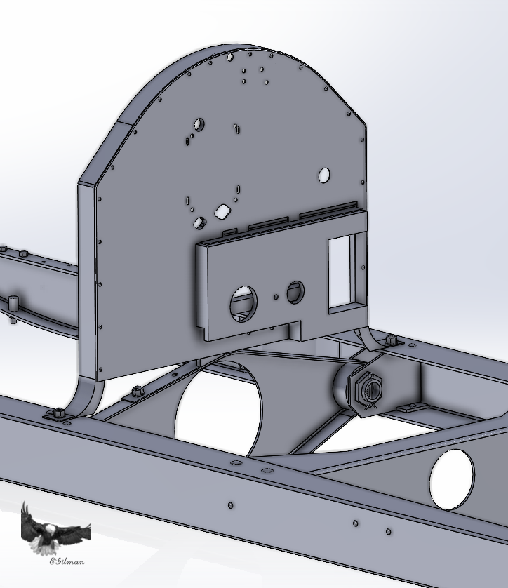
-
Most modelers put a clear sealing coat over the final acrylic color paint before weathering or shading with inks or oils... This way you can work on the weathering without affecting the acrylic paint underneath...
-
I was going to mention being sprayed too thick, but Craig got to it first... Mine has always been 4-1 mix when using heavy bodied clear coats, the consistency of running water, even wet coats as thin as possible... Leveling thinner makes it a bit less critical on the mix coats....
-
M1A1 ABRAMS by mikegr - FINISHED - Revell - 1:72 - PLASTIC
Egilman replied to mikegr's topic in Non-ship/categorised builds
Yep that is the one weakness all tanks and tracked vehicles have on the battlefield, loss of mobility... The Abrams though is a fast repair, just remove the offending damaged road wheel and repair the track, and she can rejoin the column... This happened several times in Desert Storm.... 45 minutes was the longest loss of mobility.... In Iraqi Freedom this happened to the Abrams several times as well from IED's, once the fires went out, they winch it onto a C-het and send it home where it is rebuilt into a new updated tank... It is the most survivable tank in the world today... The main weapon Insurgents use in an urban setting is knock off a track with an IED or RPG and use Molotov's dropped on it from above to set it on fire... It gets the tank out of the battle line true, but doesn't destroy the tank... But your correct, a tank without the ability to move is a sitting duck.... -
Thanks Gary... You know with a of minor color change, (white decals on the nose instead of yellow) and one sponsor swap, (engine cover decal, to Clarience Technologies from Penske Truck Rentals) and you have the 2024 winner livery as well... It's the same car....

-
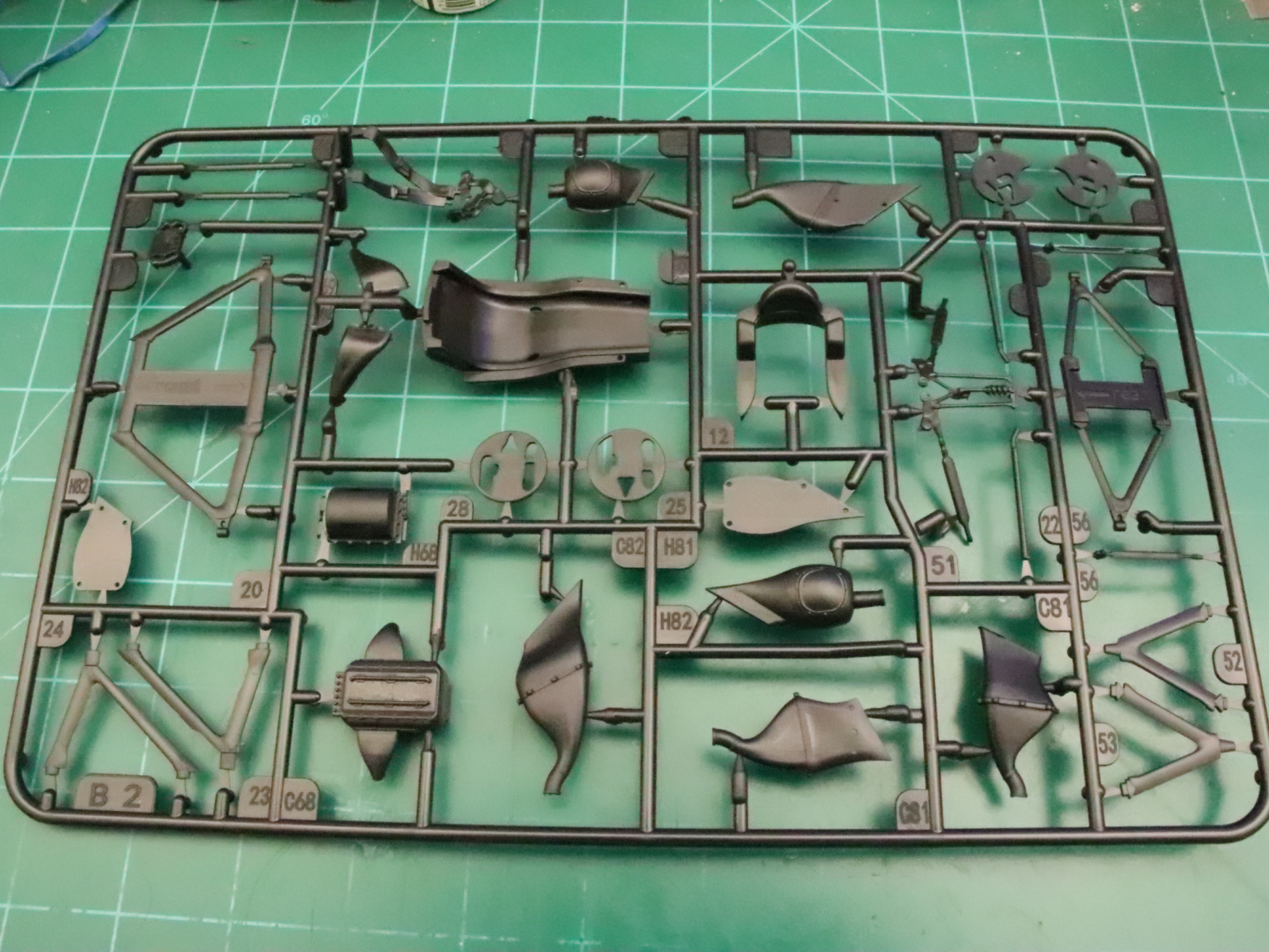
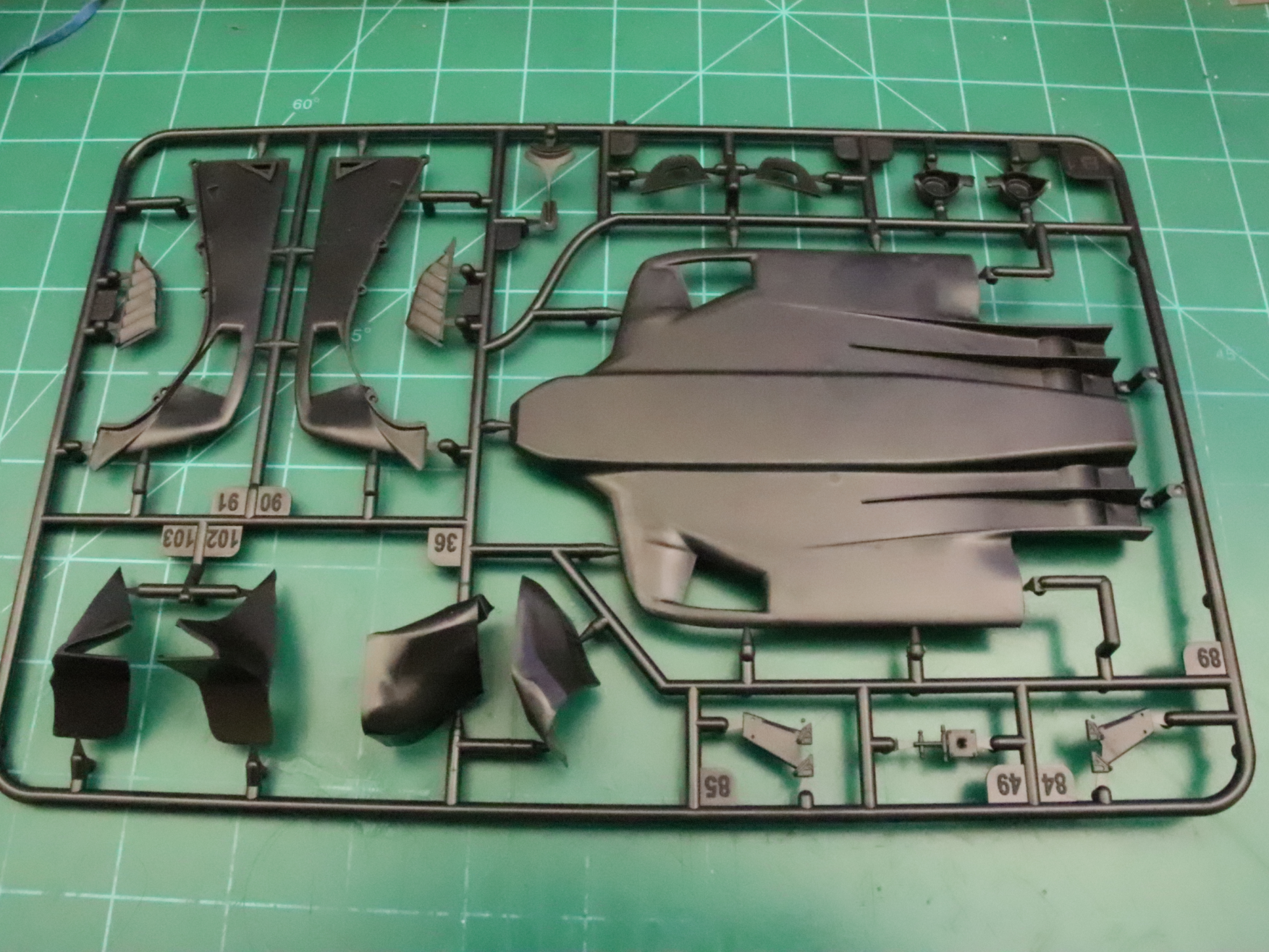
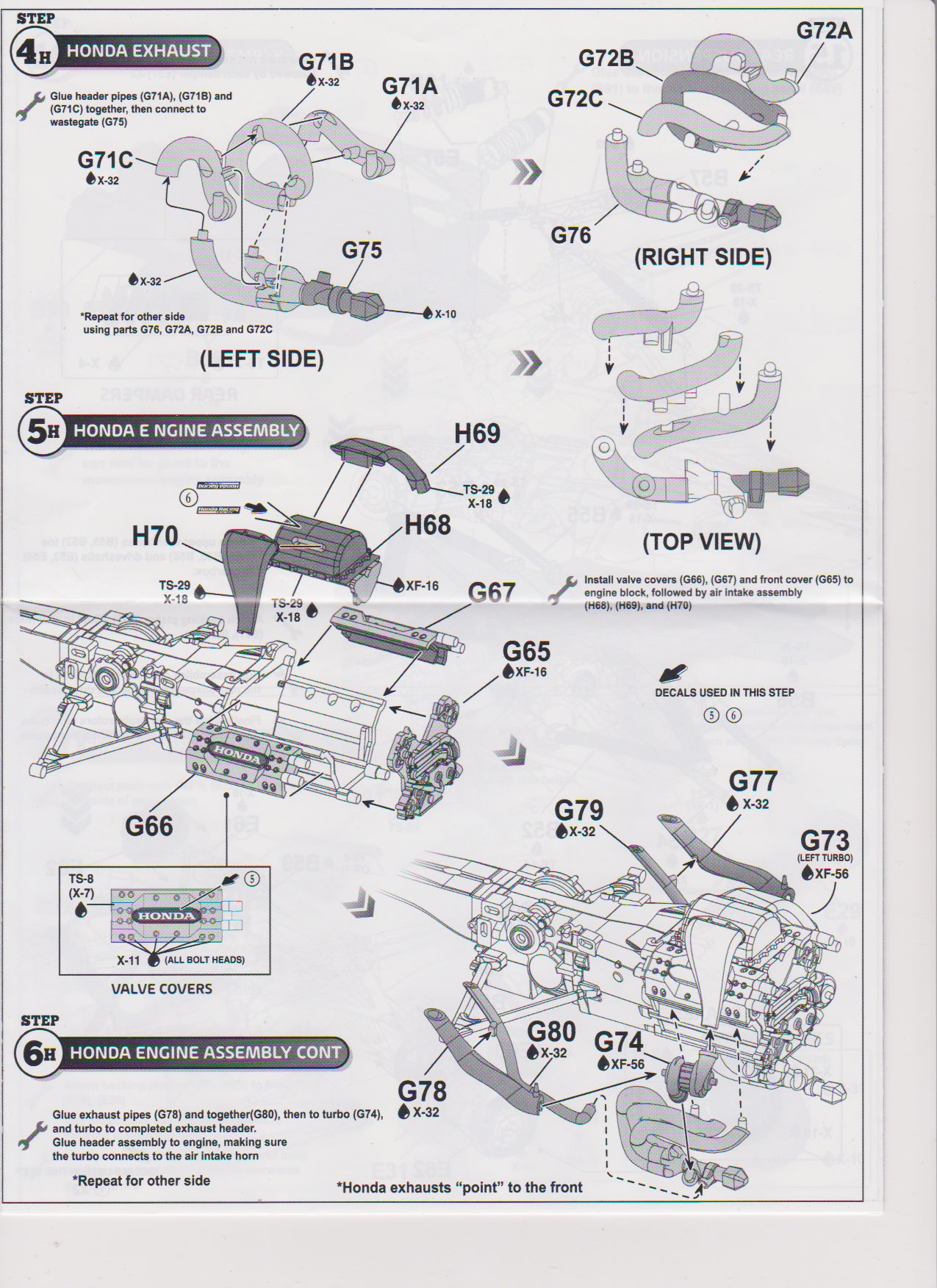
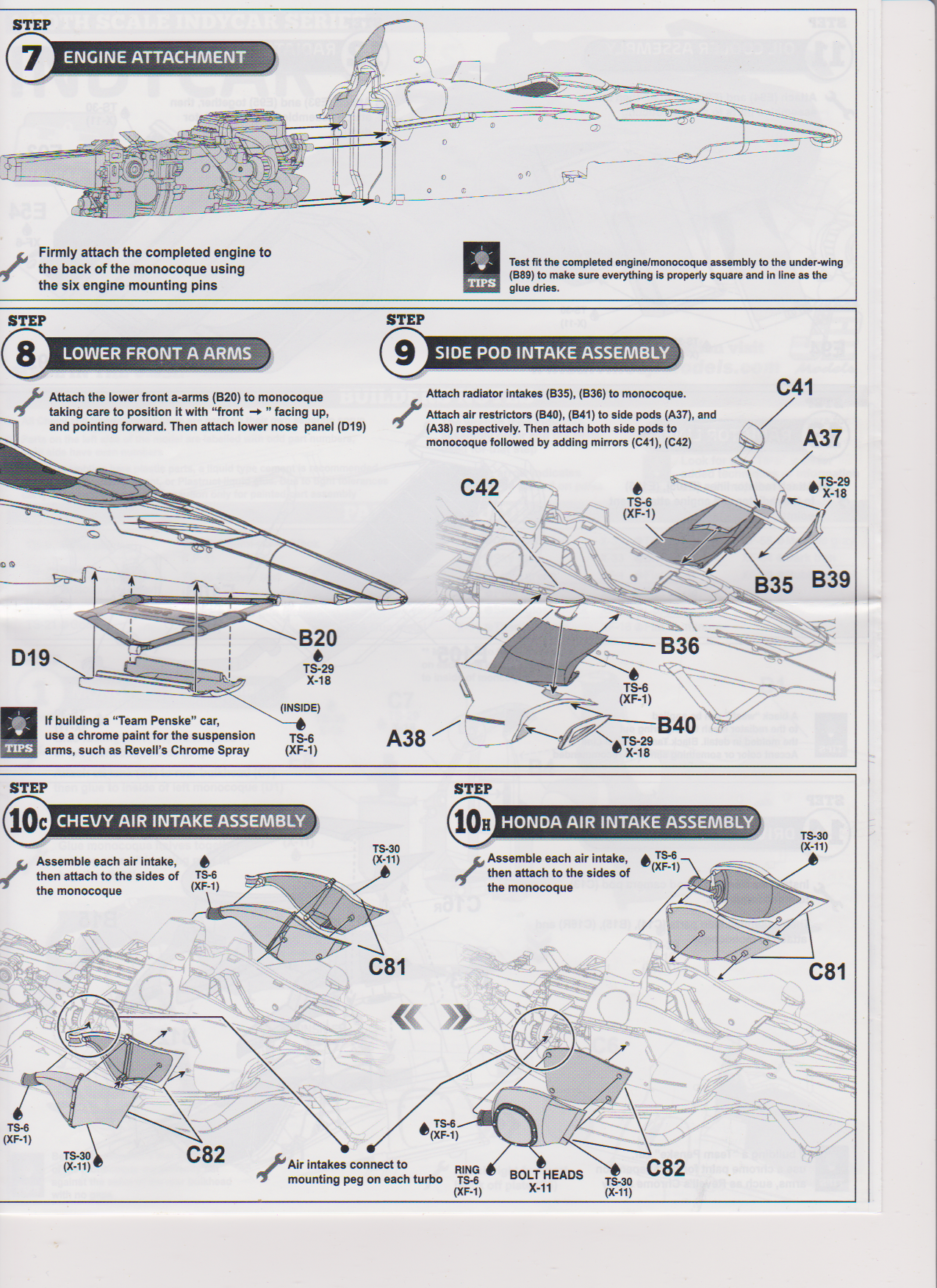
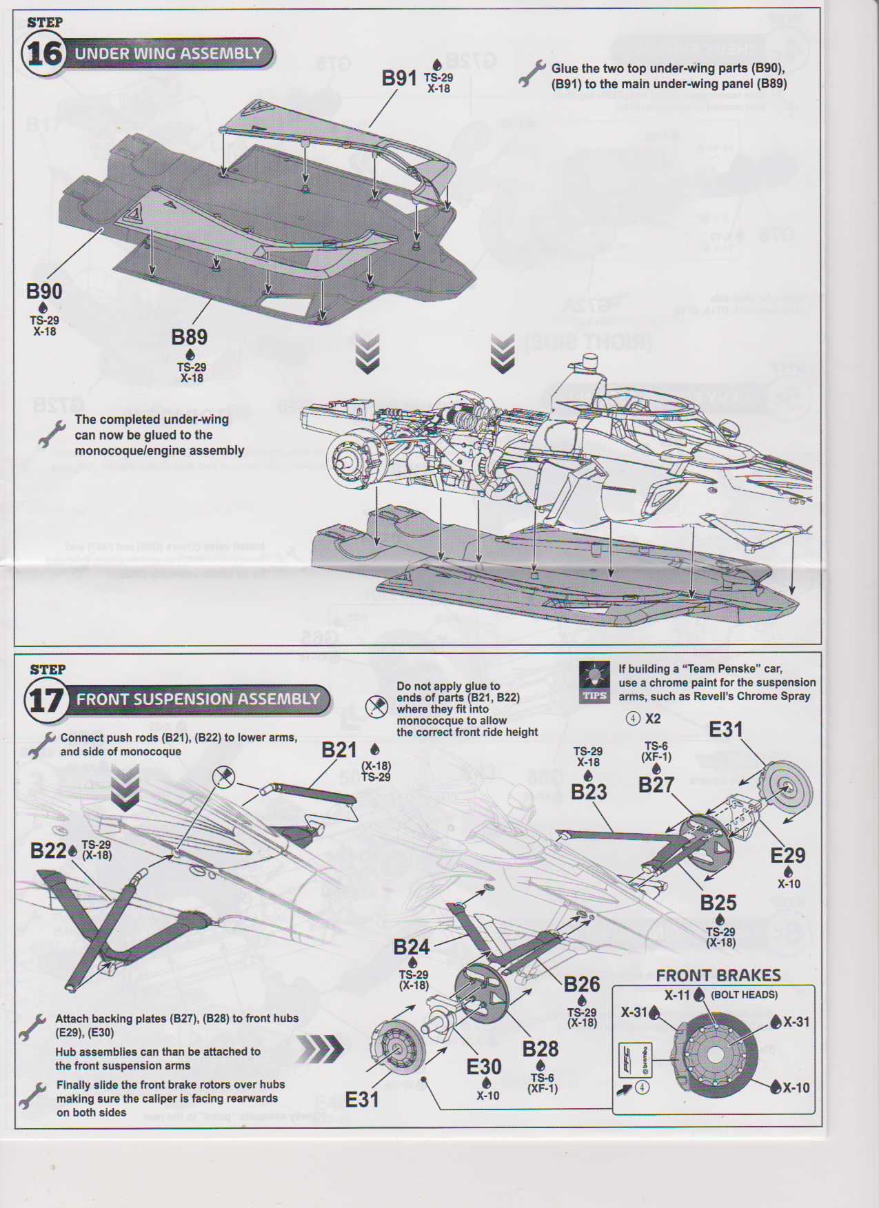
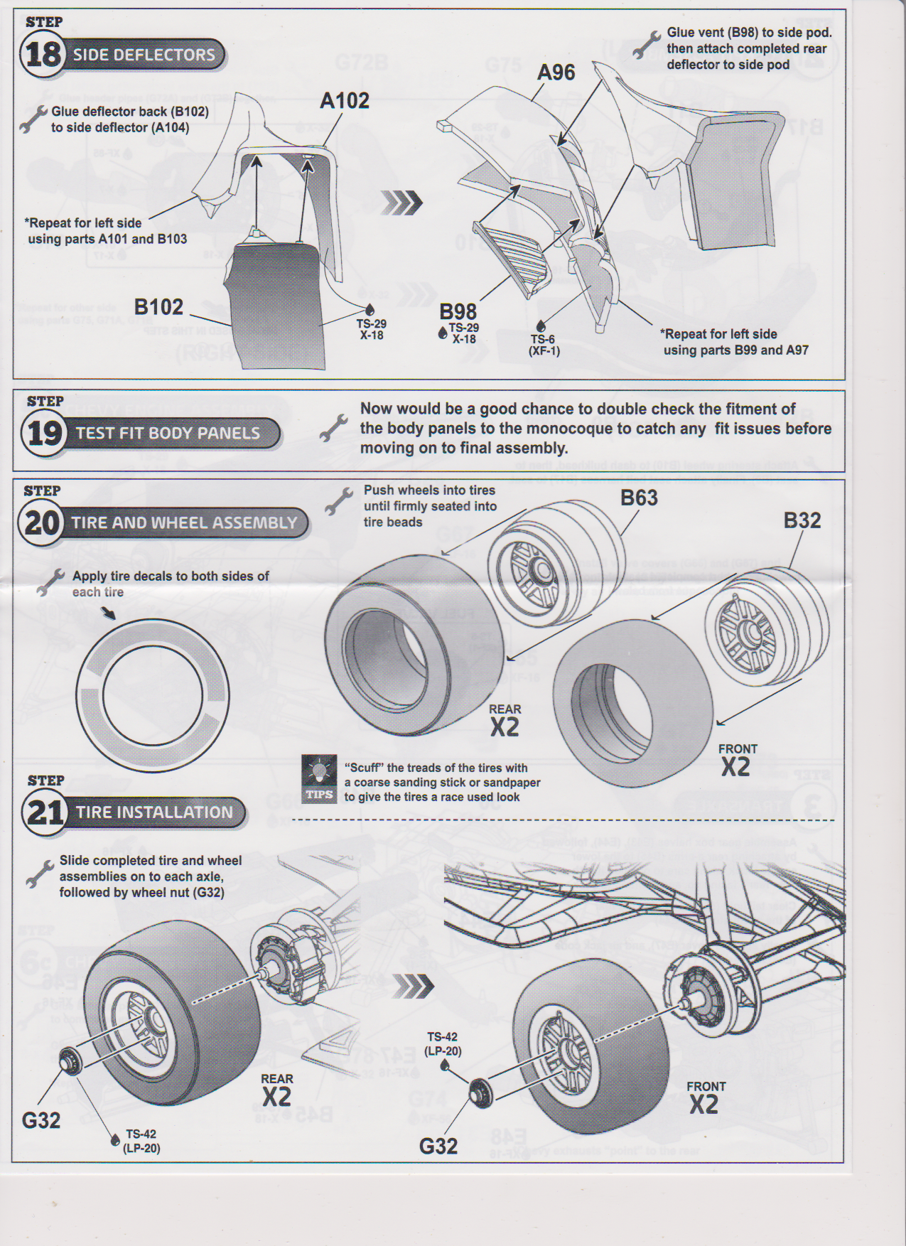
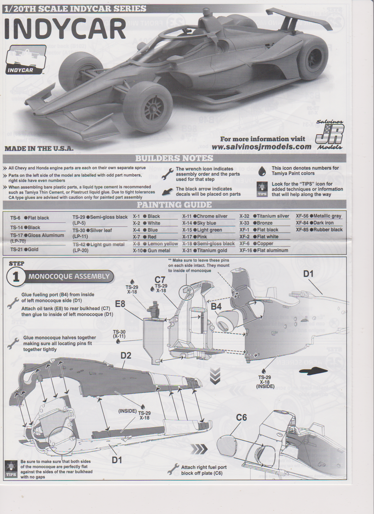
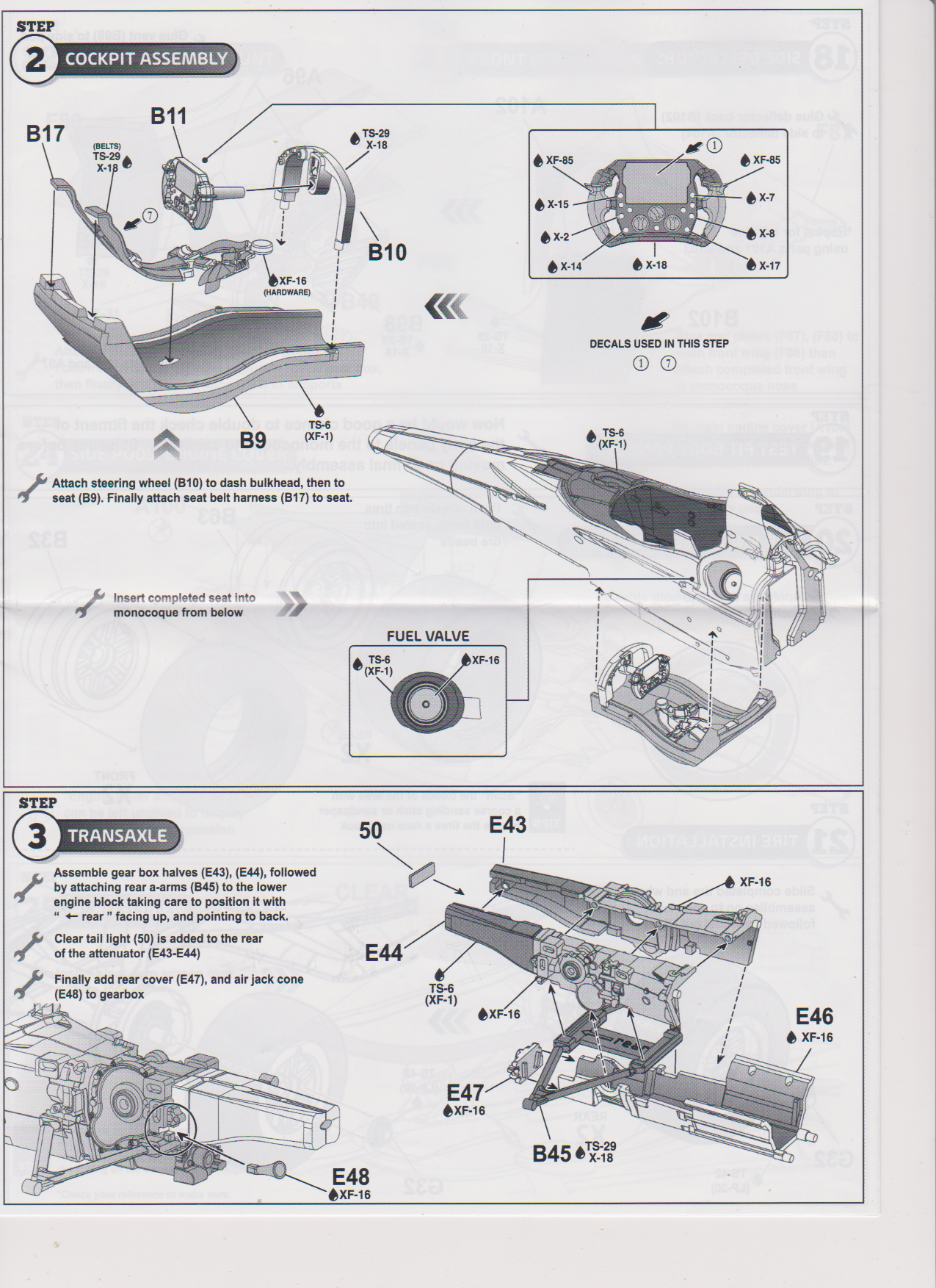
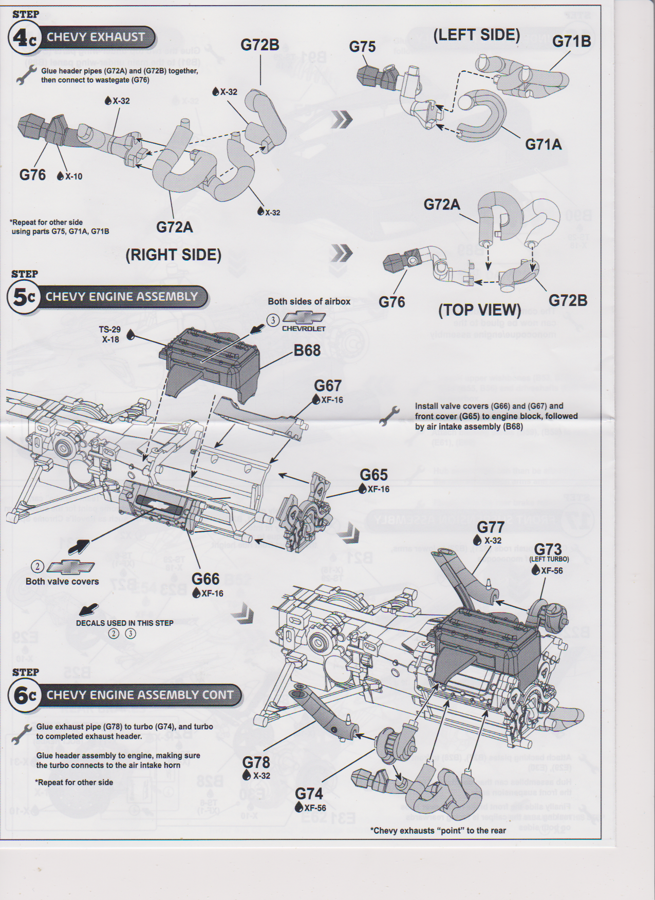
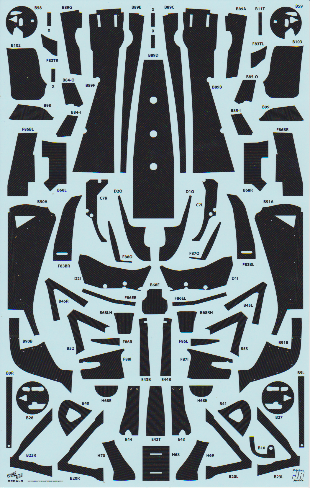
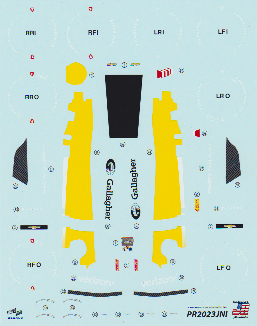
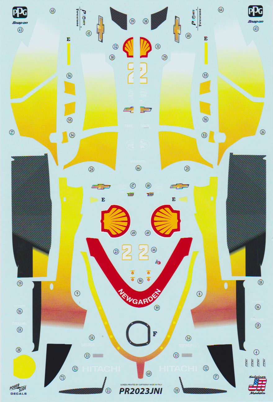
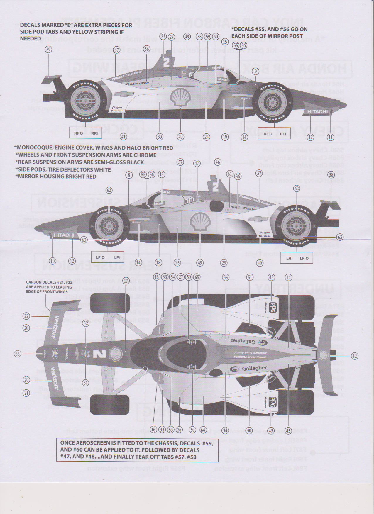
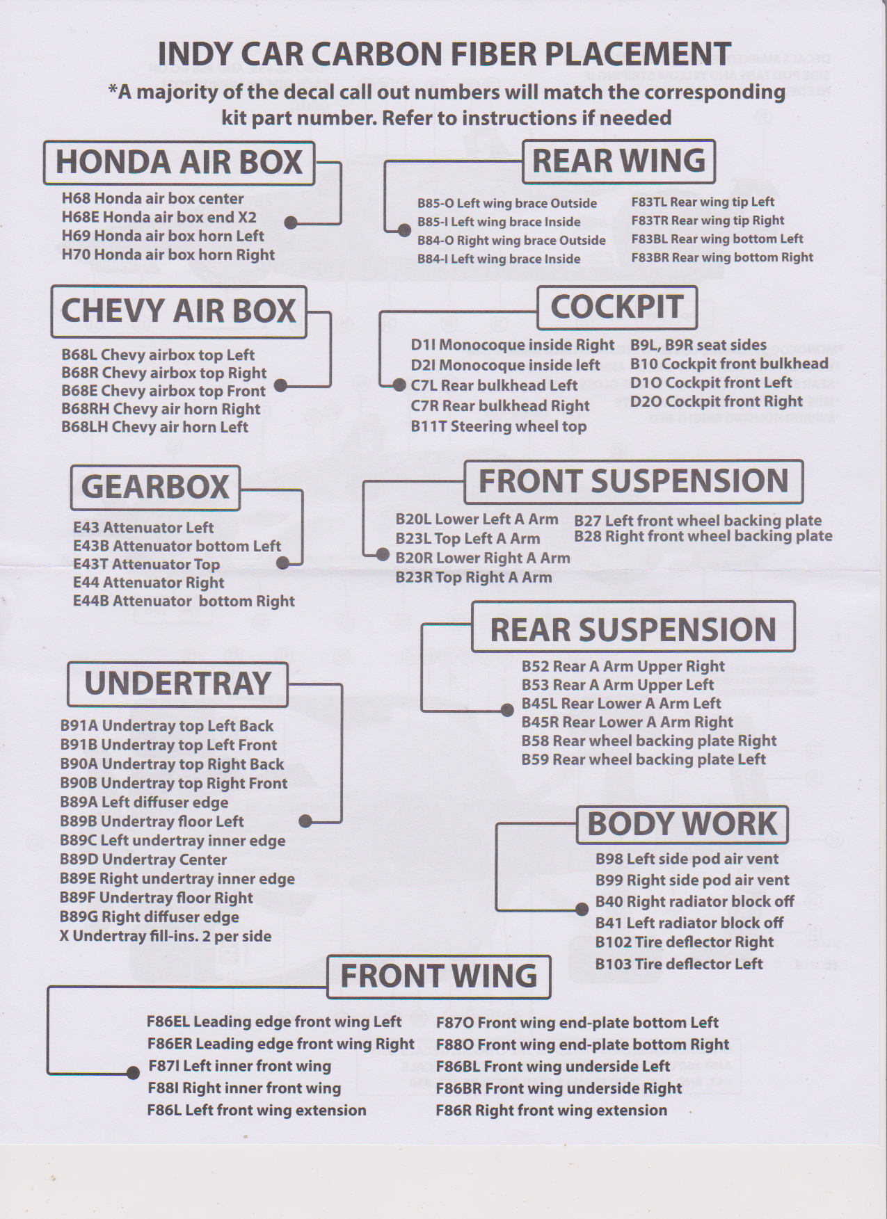
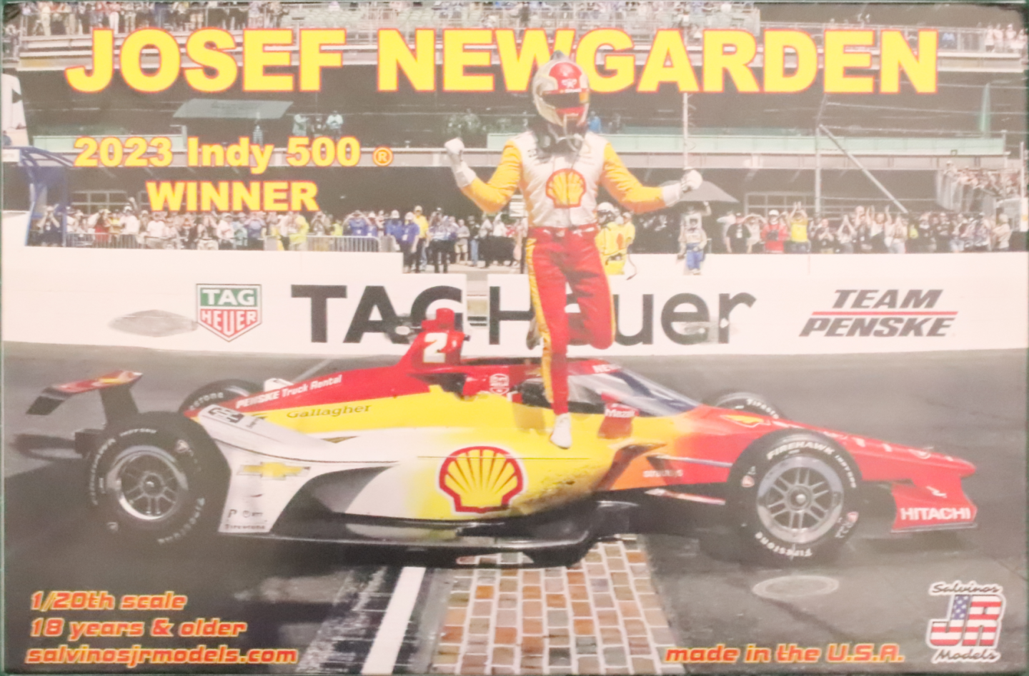
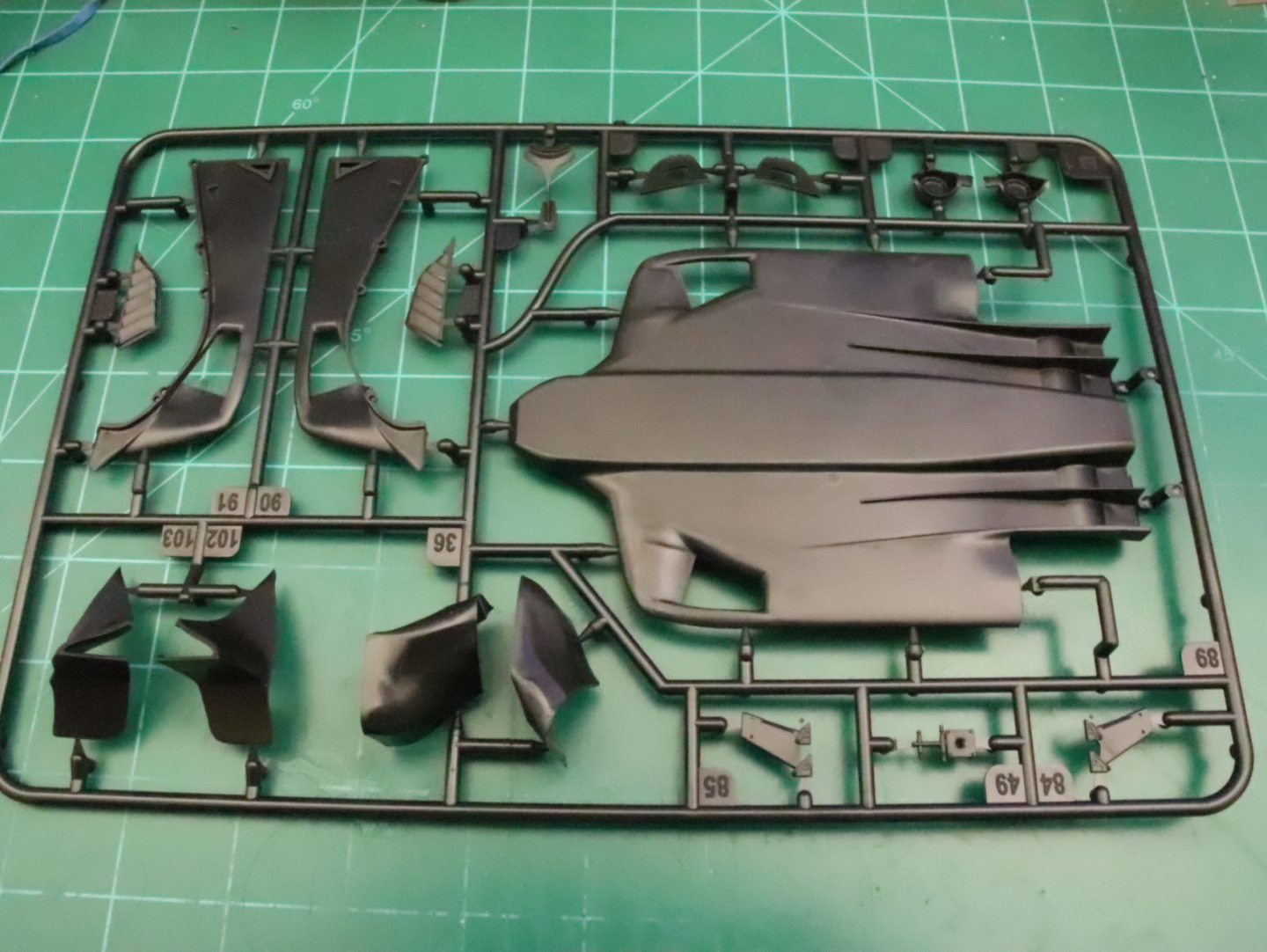
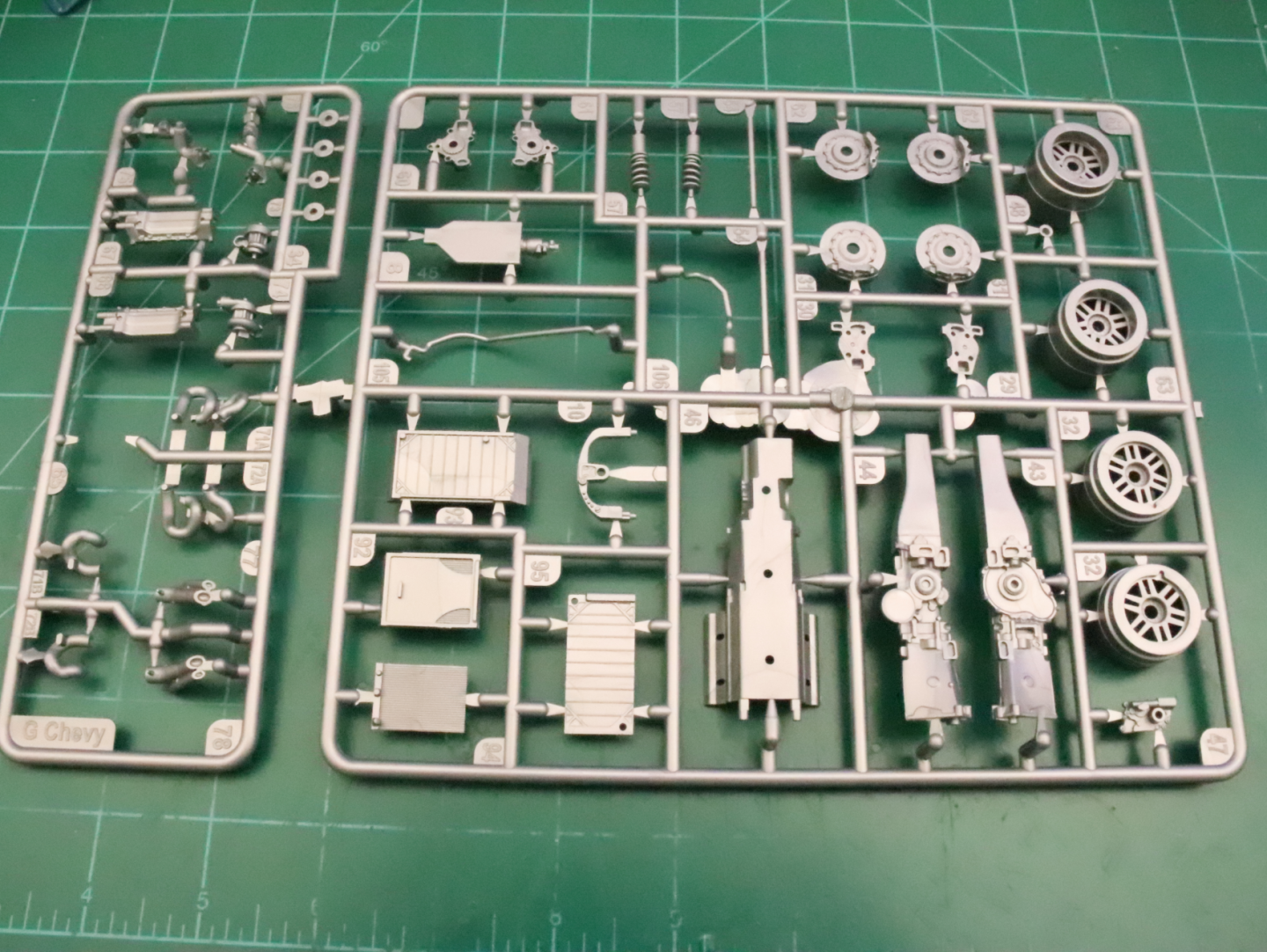
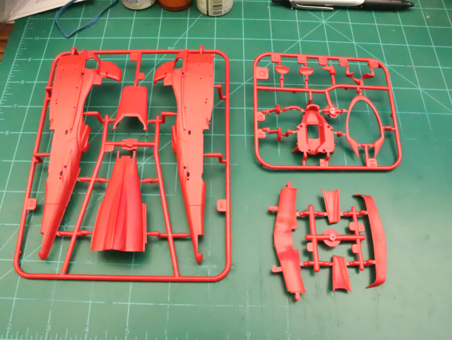
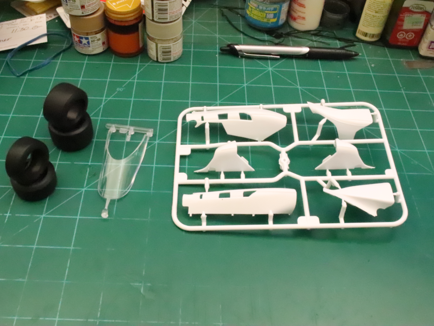
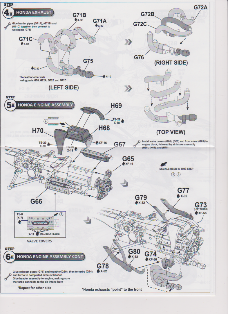
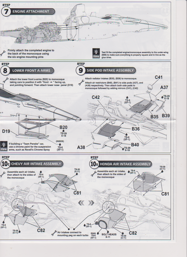
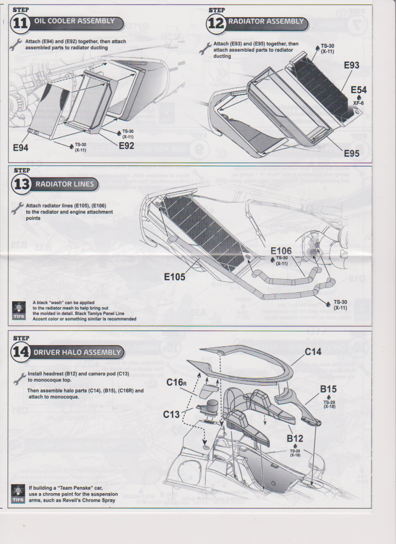
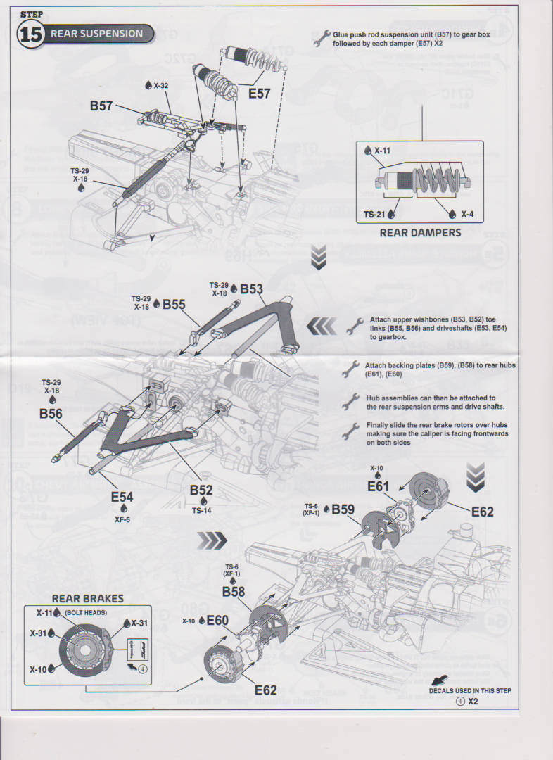
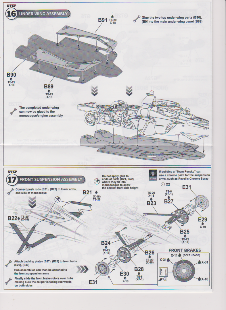
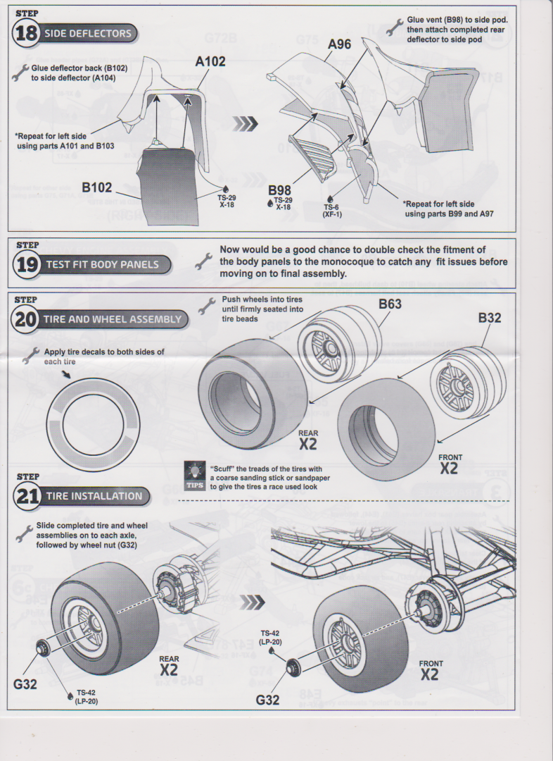
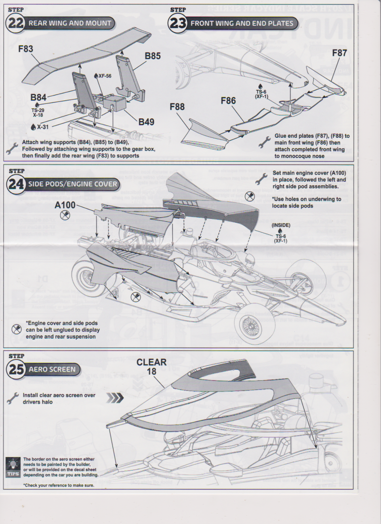
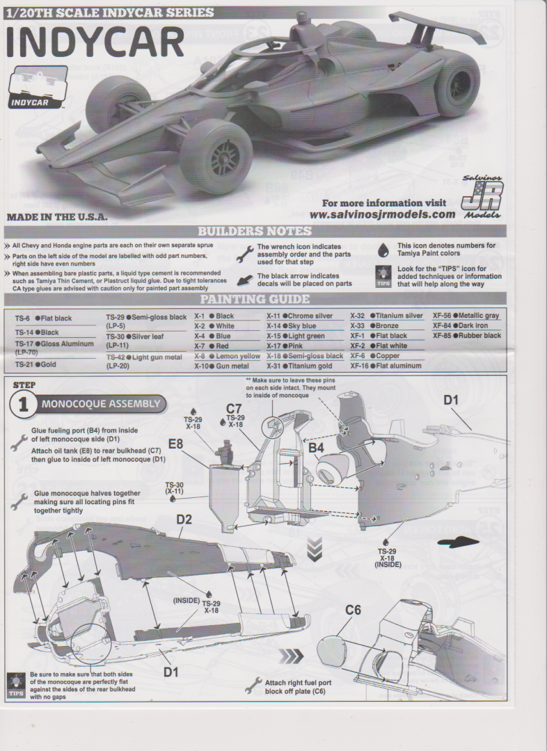
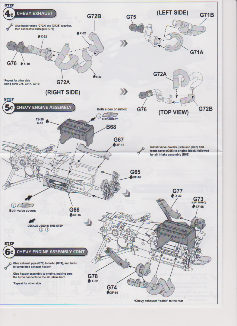
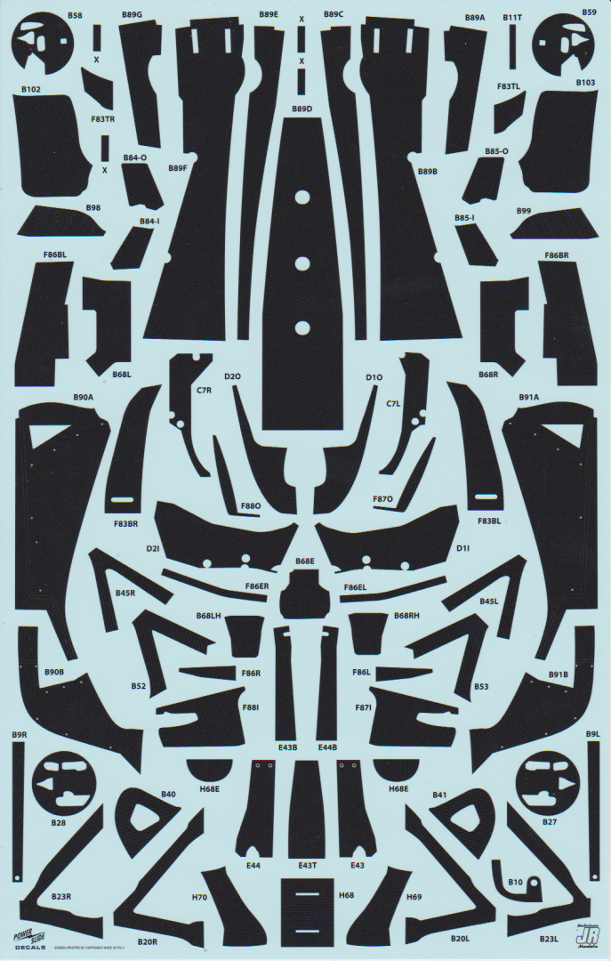
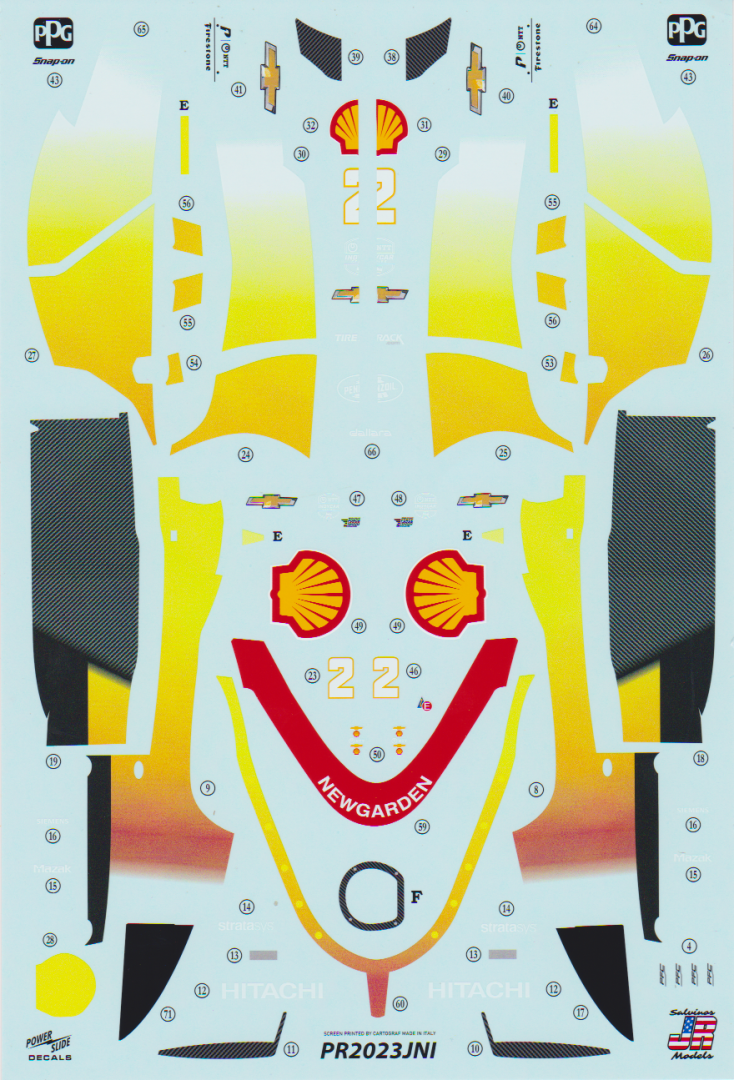
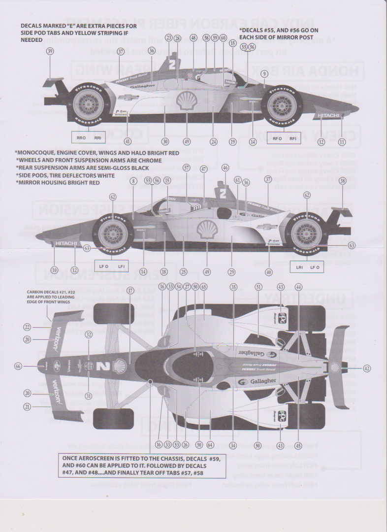
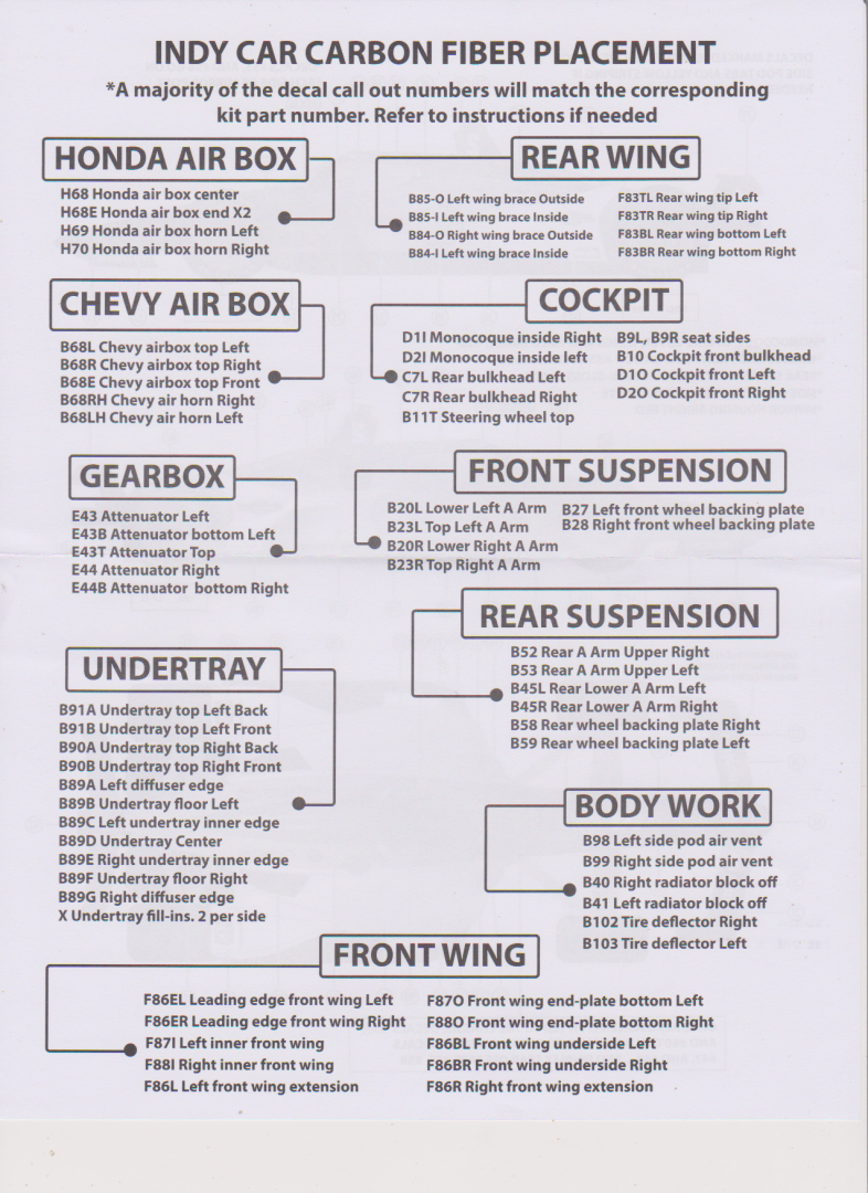
Hello this is my first Kit Review so please bear with me if I don't get it all correct... I recently received in the mail courtesy of my Paypal account and the US Mail one of the brand new Salvino's JR Models 2024 release of Josef Newgarden's 2023 Indianapolis 500 winning car, it is a first edition... I have no connection to JR Salvino except I like the Indy 500 series winners in 1/24th or larger.... And this is an outstanding release... First of all we will cover the subject, The car..... The car is a Dallera DW-12 originally named the IR-12 for Indy Racing 12 (2012 model)... Dan Wheldon was the test driver for the IR-12 and would have been the lead driver for it's introduction to racing for the 2012 season... Except he was killed in the final race of the 2023 season at Las Vegas Speedway in an IR-05 model, the model's last official race... So Dallera decided to honor all of Dan's proving and testing work by naming the chassis after him hence the DW-12 model... Every car raced in Indy has been a DW-12 chassis since 2012 and this will continue through 2026 when it is expected that the new IR-27 chassis will be ready for production... In development the DW-12 was known as the "IndyCar Safety Cell"... It is of Carbon fiber monocoque with honeycomb Kevlar internal structure... Extremely strong and light... The chassis was designed to accept different "Aero Kits" which consist of front and rear wings, sidepods, and engine cowlings.... Development of Aero Kits was open to any manufacturer, with all packages to be made available to all teams... The racing team owners rejected this so for 2012 Dallara was the only producer of the kits.... (the team owners reversed this decision in 2015) with Honda and Chevrolet producing kits as well as Dallera and several teams building their own..... That lasted until 2018 when the league again mandated that Dallera would be the only producer of "Aero Kits" as a result of several flip over crashes in the 2017 season and several serious injuries and one death resulting from body parts separating from the chassis and flying through the air as projectiles... the new rules were that all body kits had to have their parts lanyarded to the chassis so they could not fly around as projectiles and the Aero Screen would be added to the package... (a Formula I improvement for driver safety) So the car we are modeling is a DW-12 UAK18 (UAK for Unified Air Kit of 2018) All Indy cars are required to run this package and only this package from 2018 on... (The Aero Screen was added to the package in 2020) There are two engine suppliers for the 2.2L dual turbocharged package the Ilmor Engineering-Chevrolet Indy V6 (2012-present), Honda HI24TT (2012-present) mated to the same transaxle, the only one allowed, the Xtrac #1011 6-speed AGS (Assisted Gearchange System) sequential semi-automatic paddle-shift + 1 reverse... The idea is to have everyone driving the exact same hardware..... Here is a picture of the car.... In fact change the livery to any indy car raced since 2020 and the kit will still be correct.... Cause they are identical in all respects.... But how can that be? since some of them ran Chevy and others Honda power units? The kit has both engines.... Yes Salvino's thought this one thru thoroughly!!! this kit is COMPLETE!!! It can build any Indy race car from 2020 to the present and on through 2026, just change the livery... Now, on to The Kit... Cover of the box.... Nice very shiny tight top opener in heat sealed shrink wrap.... Upon opening we are presented with 4 sealed bags of sprues in 4 colors Black, Grey, Red & White, one clear sprue and one bag of tires.... 1 assembly/painting Instruction sheet, 1 decal placement instruction sheet and three sheets of Cartograph decals some of the finest decal printing I have ever seen.... Pics below.... Some of the finest injection molding I have ever seen, clean, crisp, sharp details and engraving, rivals anything else out there.... I suspect it will assemble the way it looks... (would be surprised if it didn't) The only thing missing is rain tires, a very nice set of real rubber dry track slicks are provided... Probably very fitting.... I do not know what aftermarket is going to be made available, but this kit shouldn't need it the molding is that good.... The instructions are a five page foldout sheet and are sequential, fold it like an accordian and flip the pages like reading a book... Full color codes for Tamiya paints.... Here are the individual pages.... Very clear on the optional engine, two distinctly different assembly sequences... The instruction seem very clear, concise and complete... On shiny bond grade paper very high quality.... The Decals... First instructions.... Livery Decal sheets.... Carbon Fiber decal sheet... These Cartograph decals seem to be to be a step above what the usual cartograph production quality is, I hope they do this on all their offerings.... Well that's it... All that is in the kit.... My impressions? it should build into a spectacular model, I think the quality is a cut above Tamiya's... Of course this is today production from brand new molds not 20 years ago from half worn molds.... At roughly 80.00 US? worth every penny, this is is much much better than many that sell for 50% or more higher... If you into Indy cars, this Kit will cover all cars for the last four years and two more coming years, I would expect more liveries in the future directed directly at this kit... I bought one simply cause it represented an Indy Winner for my collection I didn't care about the quality, but I'll be buying a few more to cover the Indy winners from 2020 on to 2026... A must buy if your an Indianapolis 500 modeler... EG
.thumb.png.5d99135d5dadf195858f81a6419e7e01.png)


-
M1A1 ABRAMS by mikegr - FINISHED - Revell - 1:72 - PLASTIC
Egilman replied to mikegr's topic in Non-ship/categorised builds
Absolutely, this is in the works they already have a contract ready to go for the Israeli system of rocket/drone defense which is reported to work extremely well in the combat examples they have seen... (took their armor losses down by 85%) but they are holding out for a couple of US defense contractors developing their own system right now before they commit... It's supposed to be in the next round of upgrades... They are very optimistic about it... The design thinking right now on the new MBT is for an unmanned turret with autoloading guns reducing the crew to three,... automatic targeting for the light weapons and remote control for the main gun... upgrading the engine to hybrid electric making it more fuel efficient and almost completely silent without losing any of it's speed... and a lower profile to make it more hideable.... If all this works, the next MBT will be an awesome weapon system... These kind of systems are always a balance between firepower, speed/mobility and protection... in '68 protection took a big hit with the tow missile which could turn any tank in existence into a pile of scrap iron, the Israelis learned this the hard way against soviet wire guided tow missiles during the sinai campaign against the Egyptians, but once the missiles ran out, the Israelis kicked A** They developed the reactive armor system to counter hollow charged missiles, then this was countered by first Tow II and then the Hellfire missile... two hollow charge warheads in series, the first takes out the reactive system and the second takes out the tank... then they combine the reactive system with wire cages over them... One day the missile has the upper hand the next day the armor has the upper hand... the Drones are just one of the steps in the constantly evolving process... cause right now the firepower is the dominate thing about tanks there is no defense for that Rhinemetal gun especially firing the US developed DU special shot ammo and the infrared targeting system... A tank appears on the battlefield today it's usually a pile of junk in a matter of a few minutes... Unless it's an Abrams or a Leopard II -
M1A1 ABRAMS by mikegr - FINISHED - Revell - 1:72 - PLASTIC
Egilman replied to mikegr's topic in Non-ship/categorised builds
Yep, they were the first receiving M1A1's in '88 they currently have over 1300 of them in service and a plant that assembles them from local parts and purchased high tech parts.. (mostly M1A2's) Australia was next... Saudi Arabia is 100% Abrams supplied, (over 600 in service) and Iraq also has several hundred as well as Poland has turned in all it's T72's to Ukraine in exchange for M1A2's and Romania is slated to receive them this year.. Understand one thing, NONE of the export versions have any of the special upgraded armor that US issues do, no DU backed composite armor and no DU ammo... It is also reported that a Russian armor display near Moscow has a captured M1A1 on open display... (not something the Russian's destroyed it was something captured in Afghanistan and take to Russia) Right now the only ammo capable of destroying a US operated upgraded M1Abrams consistently is fired by the M1Abrams itself... And of the nine tanks completely destroyed by tank gunfire in Iraq, 8 of them were friendly fire incidents... The earlier models of the M1 are beginning to take casualties in combat, in Syria, (yes Syria) Iraq and Ukraine, mostly to upgraded antitank missiles and improved Russian DU armor piercing rounds, usually in the side and rear armor areas, the front armor has never been penetrated by any weapon known to be used on the battlefields today... It is still, a US operated Abrams, the best most survivable and operable MBT on the planet and is about (2026-8) to undergo another upgrade... Also they are now designing the replacement for the Abrams, seeing as it is now approaching 50 years old as a design and is over 40yrs old as an operational weapons system... -
You do mean "rusted steel roof" don't you? (aluminum doesn't rust) It has no iron/carbon content and physically cannot rust... (ie an engineering impossibility)
-
{chuckle} "He who has the most tools wins!!!"
-
M1A1 ABRAMS by mikegr - FINISHED - Revell - 1:72 - PLASTIC
Egilman replied to mikegr's topic in Non-ship/categorised builds
Yeah, was very odd to see the US M-48 and M-60 in line with all that Soviet equipment also... (soon to be joined by an export version M-1 Abrams as well) The Egyptian army was the first foreign nation to receive M-1 Abrams tanks... -
The fan to turn the prop was a very nice touch.... Makes it look real...
-
Yeah I did, a beautiful job as well... The WnW instruction for this are the best... (glad that Mike got to it before I did) All I can offer is the link to the WnW page for the kit, yes it is still up and functioning, there is even more info on this airplane there... (2 versions) http://www.wingnutwings.com/ww/product?productid=3085 French version http://www.wingnutwings.com/ww/product?productid=3106 (USAS version, take a look at the rigging update page for the US version) She is looking very nice brother...
-
Amen Brother....
-
Thanks Rob... I"m a big believer in knowing from whence we came... Understanding these things helps us keep perspectives on life... The internal combustion engine is one of those inventions that was world changing... Prior to that, everything was work for you or your animals... Afterwards all we needed was a tool to do the work for us... Today very few understand that the car or motorcycle is more than a hop in it and turn the key... As a kid we used to walk to the corner store, walk to school, walk to work... Today no one goes anywhere without turning a key, not even to go around the block... And in modeling, we keep the technological history of man alive.... If we are willing to learn the lessons of it.... Give me a lever and I'll move the world, the wheel is a rotational lever, an eccentric wheel combined with a lever gives us back and forth motion as long as the wheel turns.... Everything builds upon that which came before, if we lose sight of that we lose our understanding of what we as a specie went through to get where we are, then we lose ourselves.... Your doing a wonderful job on this kit Brother... And enough of my philosophical ramblings... {chuckle} Model on my friend...
- 102 replies
-
- 11
-

-

-
Hi brother... I think a bit of explanation is needed here... All ICE's (internal combustion engines) manufactured today use electronic breakerless ignition controlled by the vehicle's CPU... Going back about 50 years the standard was a coil ignition and the Breaker function was provided by solid state components in an electronic module to provide the magnetic field collapse needed to fire the plugs... Prior to that the standard was breaker point ignition which had been around since the early 1900's... The breaker point system consists of a set of Breaker Points, a Condenser, (capacitor) and a Dual Windings coil... (a voltage step up coil) A breaker point ignition system has two circuits a primary (energizing) and secondary (discharging) circuit and how it works is simple.... The primary circuit carries low voltage... (12 volts) This circuit operates only on battery current and is controlled by the breaker points and the ignition switch.... When the ignition key is turned on, a low voltage current from the battery flows through the primary windings of the ignition coil, through the breaker points and back to the battery... (to ground) This current flow causes a magnetic field to form around the primary coil.... The secondary circuit consists of the secondary windings in the coil, the high tension lead between the distributor and the coil (commonly called the coil wire) on external coil distributors, the distributor cap, the distributor rotor, the spark plug leads and the spark plugs.... As the engine rotates, a cam on the distributor shaft turns until the high point on the cam causes the breaker points to separate suddenly.... Instantaneously, when the points open (separate) current stops flowing through the primary windings of the ignition coil.... This causes the magnetic field in the coil to collapse around the coil. The condenser (capacitor) absorbs and stores the energy to prevent arcing between the points each time they open. By sucking up all this energy the condenser speeds up the rapid collapse of the magnetic field..... The line of flux in the magnetic field, (hi magnetic potential to low potential) cuts through the secondary windings of the ignition coil, creating a very high voltage (50 to 75,000 volts for this early engine) - high enough to jump the gaps between the rotor and the distributor cap terminals, and the electrodes at the base of the spark plug..... Assuming that the engine is properly timed, the spark reaches the air-fuel mixture in the cylinder and combustion begins.... As the distributor continues to rotate, electrical contact between the rotor and distributor cap terminal is broken, stopping the secondary high voltage flow.... At the same time, the breaker points will close to re establish the primary low-voltage circuit, allowing primary current (12 volts) to flow. This primary current will again create a magnetic field in the coil primary windings and the cycle is repeated for the next cylinder in the firing order..... This process takes place within a few milliseconds. In fact, it happens approximately 18,000 times per minute at 90 miles per hour. There is no "Condenser Coil", the condenser and coil are two distinct different parts of the system..... The condenser on your bike engine is that little silver cylinder mounted to the side of the distributor.... The condenser is not hidden, the ignition coil is... Not criticizing here, just offering the correct understanding of what the equipment is supposed to be and how it works... EG
-
Keeping my head in the game.....
Egilman replied to Egilman's topic in 3D-Printing and Laser-Cutting.
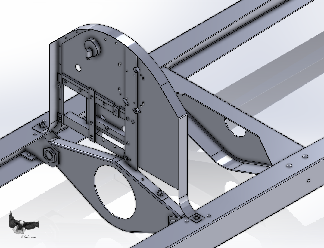
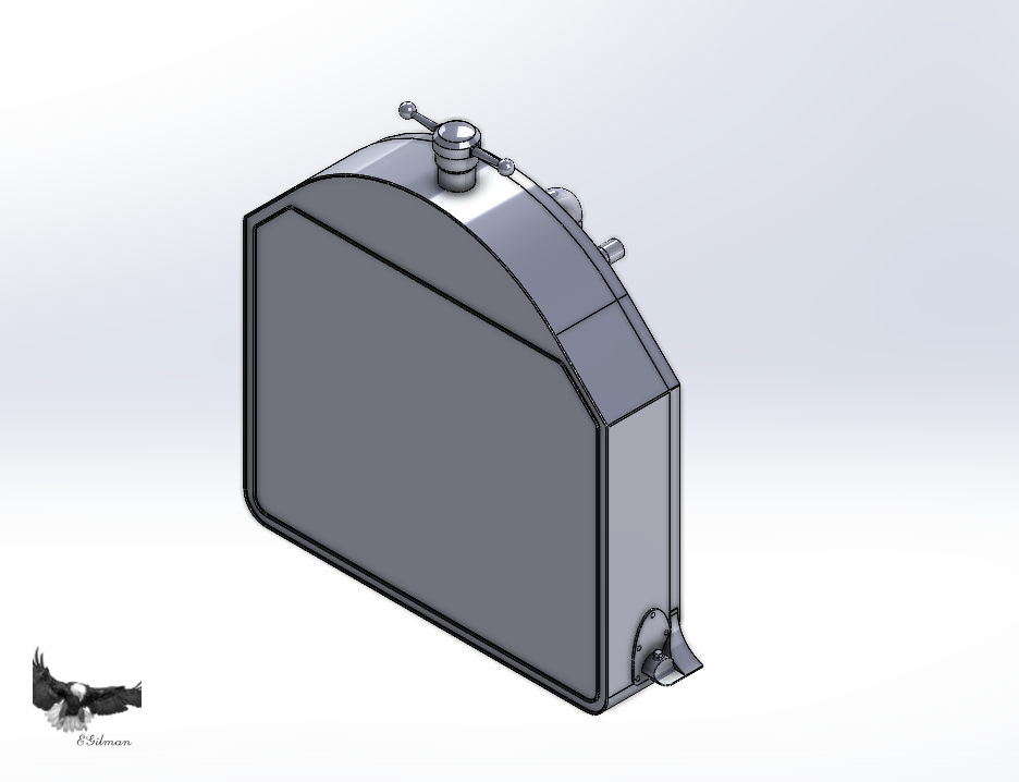
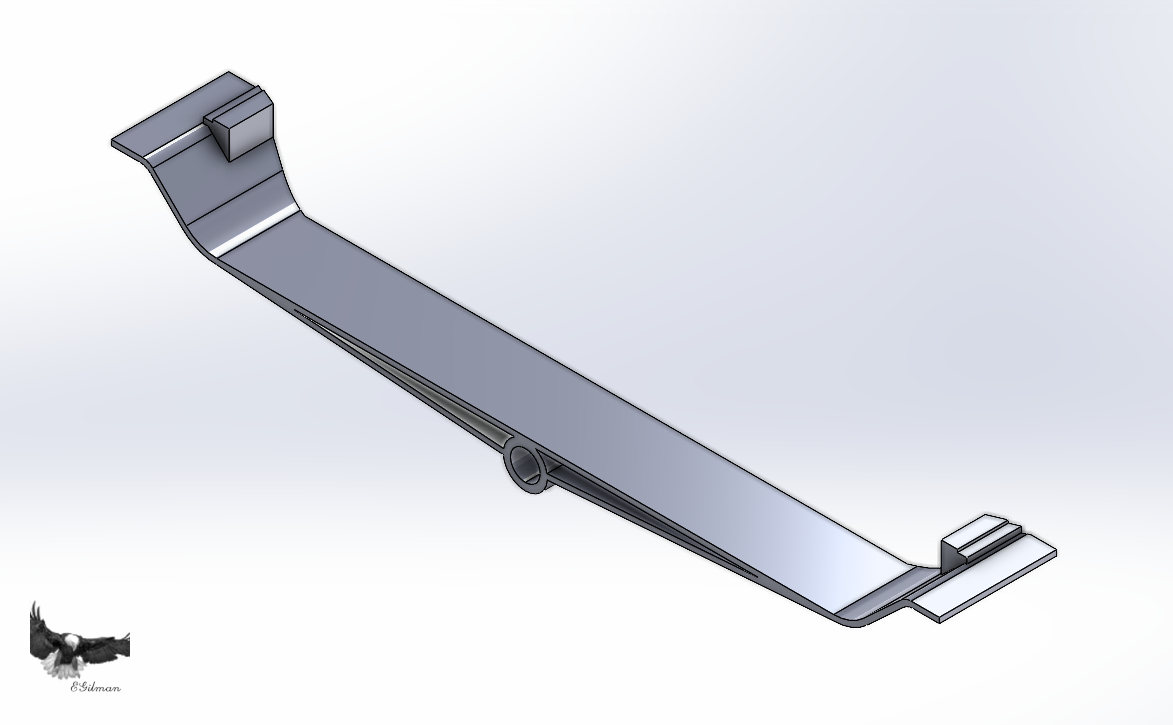
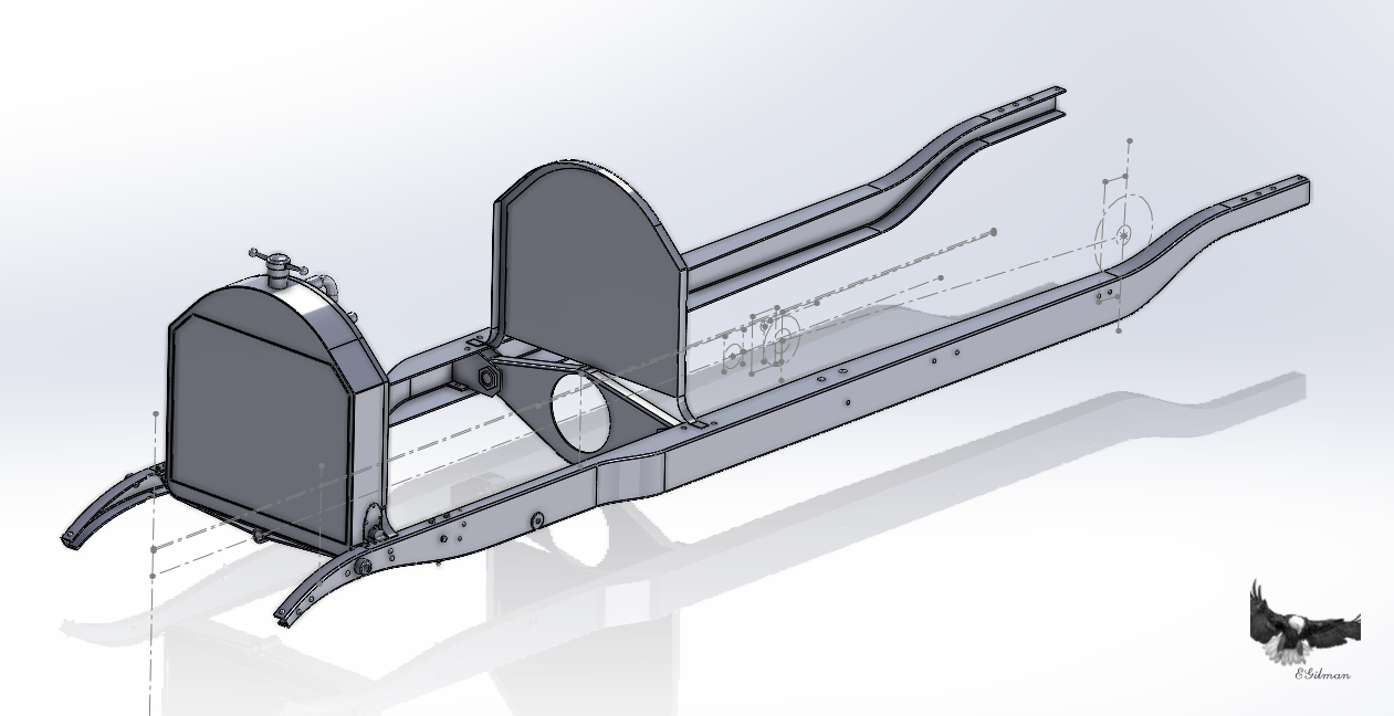
Hey Brothers it's time for another update.... This is prep, setting up the model to build the forward firewall.... We first start with the general shape, this comes from the Radiator, it has the exact same shape as the firewall... And the Radiator sits on the Core Support, all radiators in all cars do... The core support.... Now the core support has two functions, to take the weight of the full Radiator but also to locate it and affix it to the frame so it doesn't move about... It's location in the frame.. Now the design only goes far enough to create it, it will be attached to the Radiator itself when the model is done... The Radiator... And the Radiator's final location.... And here is the results of the prep work... The outer frame is made from hand forged angle iron and the actual sheet is .060 Steel... You can easily see the shapes are identical... And with everything out of the way it's easier to see what is going on.... Anyway this is the state of the model today... Onwards!!!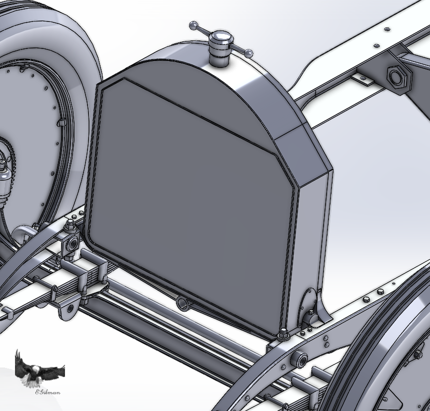
-
“Capt. Eddie” A-7 Corsair II by GrandpaPhil - 1/48
Egilman replied to GrandpaPhil's topic in Non-ship/categorised builds
Ah yes the lost art of printing stenciling... Completely old school I love it!!! The camo look good as well.... (using grey greys instead of grey blues) USAF A-7E Corsair II at the Davis Monthan boneyard....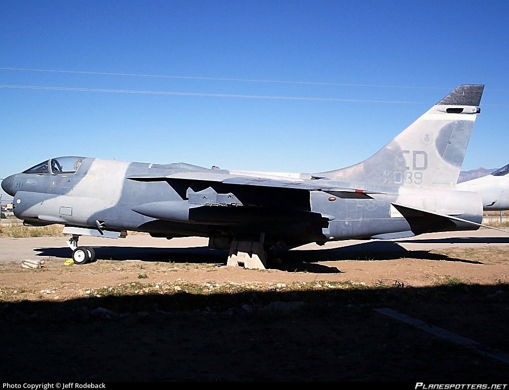
-
Keeping my head in the game.....
Egilman replied to Egilman's topic in 3D-Printing and Laser-Cutting.
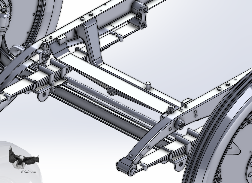
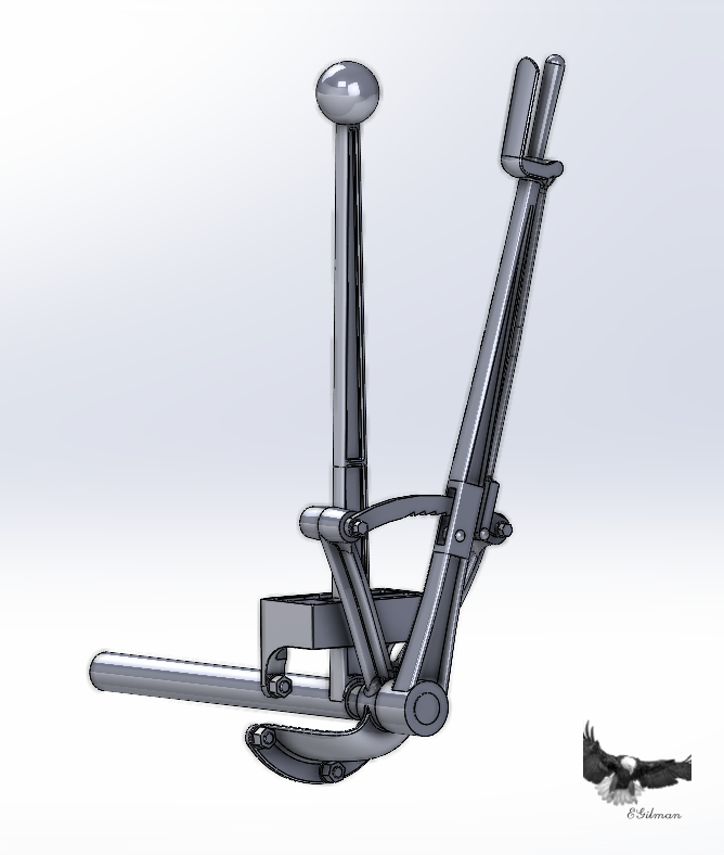
Another short update brothers... Brake and Shift levers.... This required a complete redesign of the ratchet mechanism once I got a good look at what it actually is... Where it resides.... And it's shaft is connected to the Thrust Collar where it is supposed to be... Making progress brothers... I think I'm going to change the arc of development here, right now, it is easy to develop the forward firewall as everything is open with nothing to interfere with the design process... If I start putting the clutch pedal and steering gear in now, then the firewall has to be built around them... It adds a whole lot of complications... Right now I can build the Firewalls with an essentially clear slate and adjust them later if I need to for fitting the accessories.... And the clutch is anything period that look the part, as I still have absolutely no info on what it looked like except for it being a tapered clutch... The clutch throwout mechanism is a mystery, I know where it goes, (well where it's cross shaft goes) but what it looks like is anyone's guess... I do have a mechanical cut-away drawing of the Marmon 32 1914 clutch mechanism from the flywheel to first universal... Was thinking of adapting it to this so at least something that looks like a clutch mechanism is present when built... But I'm not sure if I want to do that.... It may be the only way to go.... And the firewalls are essential to laying out the body in the future...., It's easier to put it in place now... anyways Onwards!!!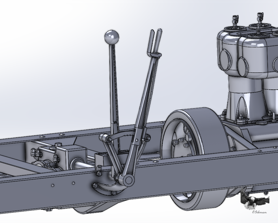
-
We are going to see pics correct? Pretty Please.... {chuckle}
-
Yury, (St George's Models) does make some beautiful kits Doesn't he... I need to get a Durkopp and a Bussing as well for my 150mm K16 Gun.... (nice to see I'm not the only artillery nut around)
-
Keeping my head in the game.....
Egilman replied to Egilman's topic in 3D-Printing and Laser-Cutting.
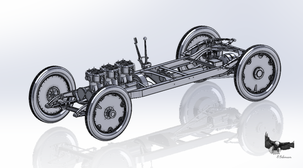
Thank you Gary, And welcome aboard... Was looking for something I could do while under medical issues... This is working out well I think... Certainly... I'm currently using Solidworks 2023 for this, I won't upgrade to 2024 until the year passes.... I will use Rhino for doing ship hulls when I get that far.... Not that it can't be done in SW, it's just that Rhino is better for ship hulls... Yes as detailed as I can make it, I'm designing in 1/1 scale right now, a virtual copy of the full sized car... Most models are initially designed this way on the computer, its easier and you can scale it to any scale you want when the basic design is finished... Yes this very detailed model is intended for 3D printing and yes I will have to adjust the model for it... as you scale it down for printing you will lose some detail, as it will scale so small as to be invisible some of the details will have to be oversized so they will show... you also have to decide how the parts will fit together and an assembly sequence that doesn't change the model in any appreciable way... Like on this model the 1/2 inch truss rods when scaled to 1/12th scale will be .042 inch in diameter a 1/8th" thick panel will be slightly thicker than a piece of paper.... (and you won't be able to print a .030 thick body skin panel, it will have to be thickened) So yeah, the model for printing will have to be adjusted so it's capable of being built... Unfortunately you will lose fine detail when the developments for scale printing are complete... The good model designers do it this way, it's the only way.... Otherwise you miss things that should be there but because you didn't design it at the start it isn't there on the model... Now I've chosen a specific model at a specific point in it's life, most of it's life it had a belly pan to keep dirt and debris out of the running gear, but when it ran the first Indy 500, it wasn't on the car, so I'm not designing it, this is a model of the first Indy Winner... (as it was raced, not like it is today) Takes a bit more work to do it this way which is what makes it even more fun... I have no illusions, there are several thousand people following this on the net, I'm sure a few of them are taking my images and doing exactly what I'm doing but using my work instead of their own...... It goes with the territory...

.png.c169cace5093a743eab82930d8fda9b6.png)