Egilman
-
Posts
4,379 -
Joined
-
Last visited
Content Type
Profiles
Forums
Gallery
Events
Everything posted by Egilman
-
 China directly? forgetabout it, eBay? I've had both good and bad results with items from China.. My experience says it depends on how much business they get from eBay, if a lot, than you may see a good result, If Not, they may abandon their eBay account... For items like this, Amazon is the better option even if it's coming from China for eBay I don't buy from China except with Paypal, cause paypal will yank the finds right back out of their account if it isn't satisfactory... They probably won't want the material back cause it IS so inexpensive... But ya the very very poor shipping was a serious issue here... You should be getting your money back... (but as with everything China, don't hold your breath waiting) And brother, just in case they want it back, I wouldn't do anything with it till you know for sure... It's one of those items that isn't worth shipping back I know, but then there is the oddball Chinese for ya and eBay may require it.... But it is a product that can be glued together into whatever shape you need... Frustrating yes, I think we've all gone thru it at least once, it's one of the things Chinese shippers are famous for....
 -
Only cause you haven't tried yet brother... Doing them as small as you have been doing should make the larger ones easier I imagine... Anyway I would have a lot of confidence in your ability to paint any figure at this point...
-
Keeping my head in the game.....
Egilman replied to Egilman's topic in 3D-Printing and Laser-Cutting.
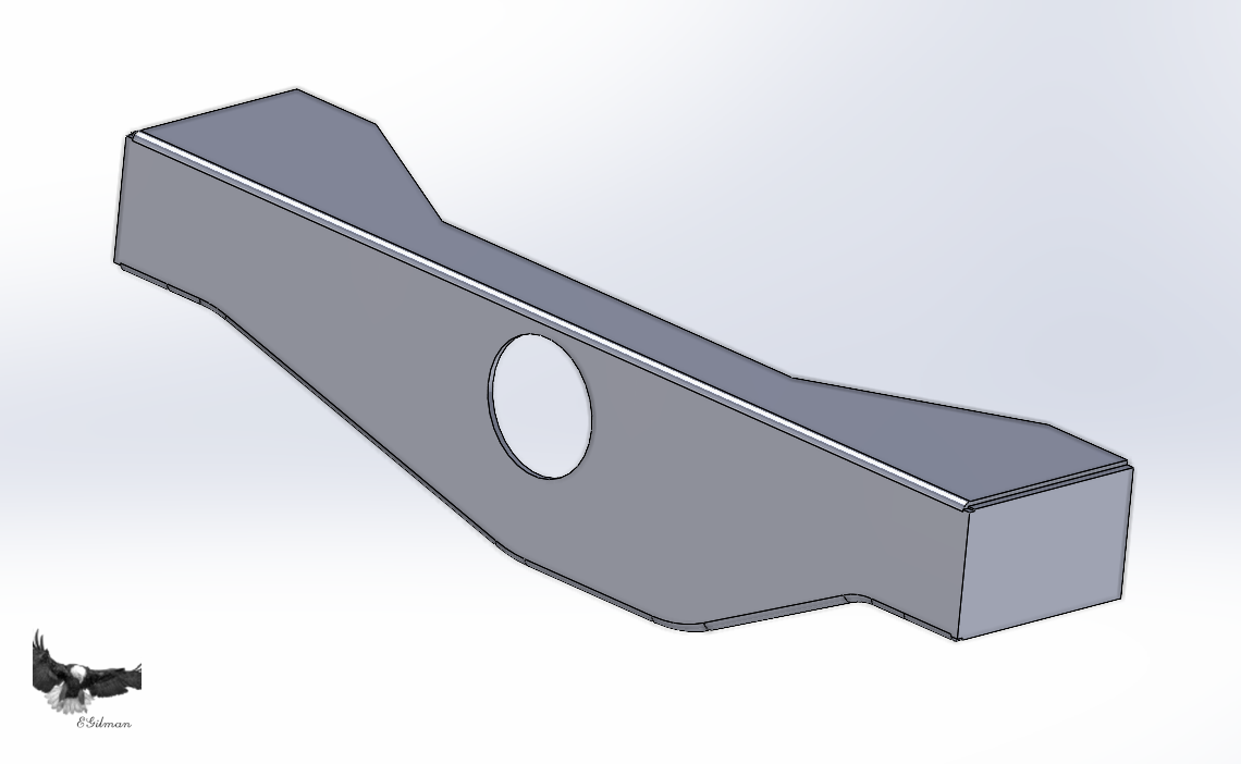
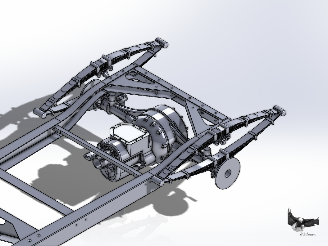
Well I need to continue on with the process... We are working on Version II of the thrust collar.... This is a part I designed a few months ago using the only info I had at that time... This is what it looked like and the pic it was derived from.... Yeah one single view, from one angle.... A little hard to get a correct shape... Since then a few more images have come into my possession which show what it looks like from the rear.... We have seen these images before but in these I've enlarged a section of each side and have started lining it out for measuring... One of the things we look for is matching points in each pic, The truss rod slot in the collar is one of those points but even more important is the stud/nut positions.. We have three in one pic and two in the other but there is one that shows in both pics so they have to be in the same position on the part, the lower center stud... Now given the information in the top view we see that there is an upper and lower stud in the middle there is a upper and lower corner stud on the left and a single center stud on the right... Also that the studs are mounted to standoff tabs on the casing of the collar housing.... This is the start of the pattern we will make... All the tabs are the same relative size to one another, they all carry the same size stud and are secured by the same size nut.... Now the one stud we don't see in the end view pics is the upper middle one, we see it in the top view..... This is where the artsy part comes in, none of the pics have the same frame of reference, all we can do is extract patterns and points from the images and make them fit the 3D model... This is the time of draw, adjust, draw some more, adjust some more until you get something that actually looks like the pics... It's hard to describe the process as nothing is concrete... Basically your trying to make a 3D model that looks like what your seeing in the pics.... So at this point I'll be figuring out how to model this part I will first try to adjust the previous one and failing that design a new one... Anyway this is the process I go thru for every part I make in SW... Now back to designing the part... Onwards..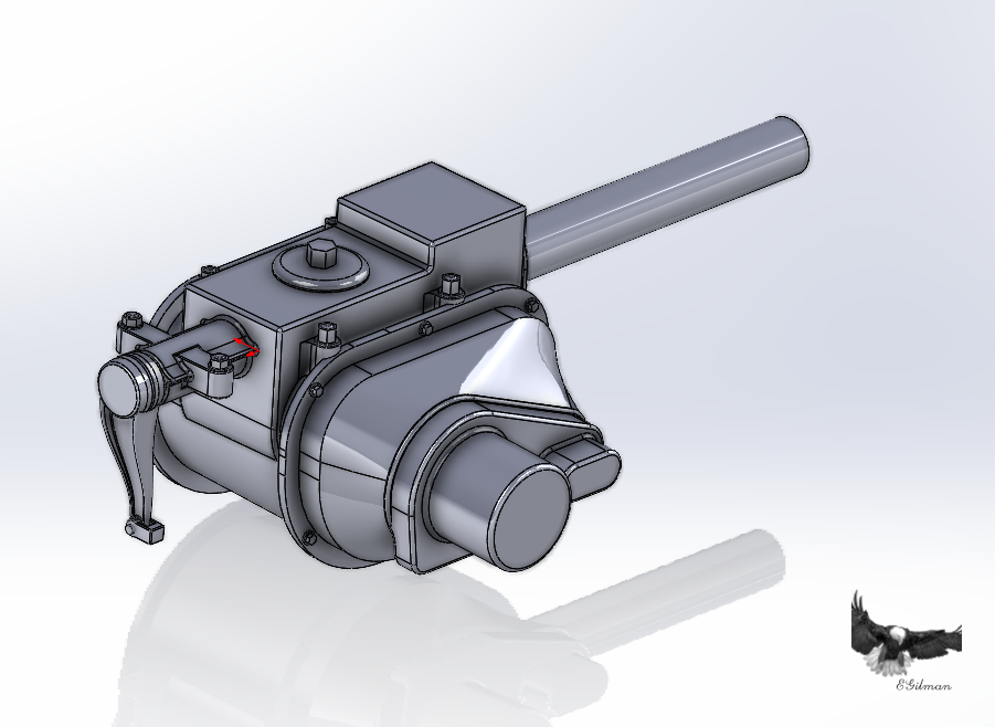
-
Keeping my head in the game.....
Egilman replied to Egilman's topic in 3D-Printing and Laser-Cutting.
Thank you Mark... I dunno about master anything, {chuckle} it's just the way I've learned to do it over the years.... Like I said, it works for me... If it helps someone else then great, that is the point.... This stuff isn't very technical, and one can get buried in all the supposed mandatory technical requirements when what we really are doing is simple copying of an image.... And people have been doing that since the invention of charcoal and stone cave walls... It's just the tools to do it are so much more capable than back then.... Thank you for the compliment.... -
Keeping my head in the game.....
Egilman replied to Egilman's topic in 3D-Printing and Laser-Cutting.
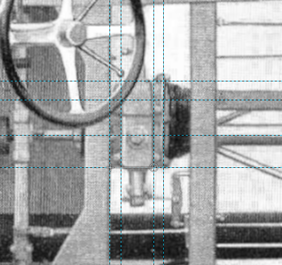
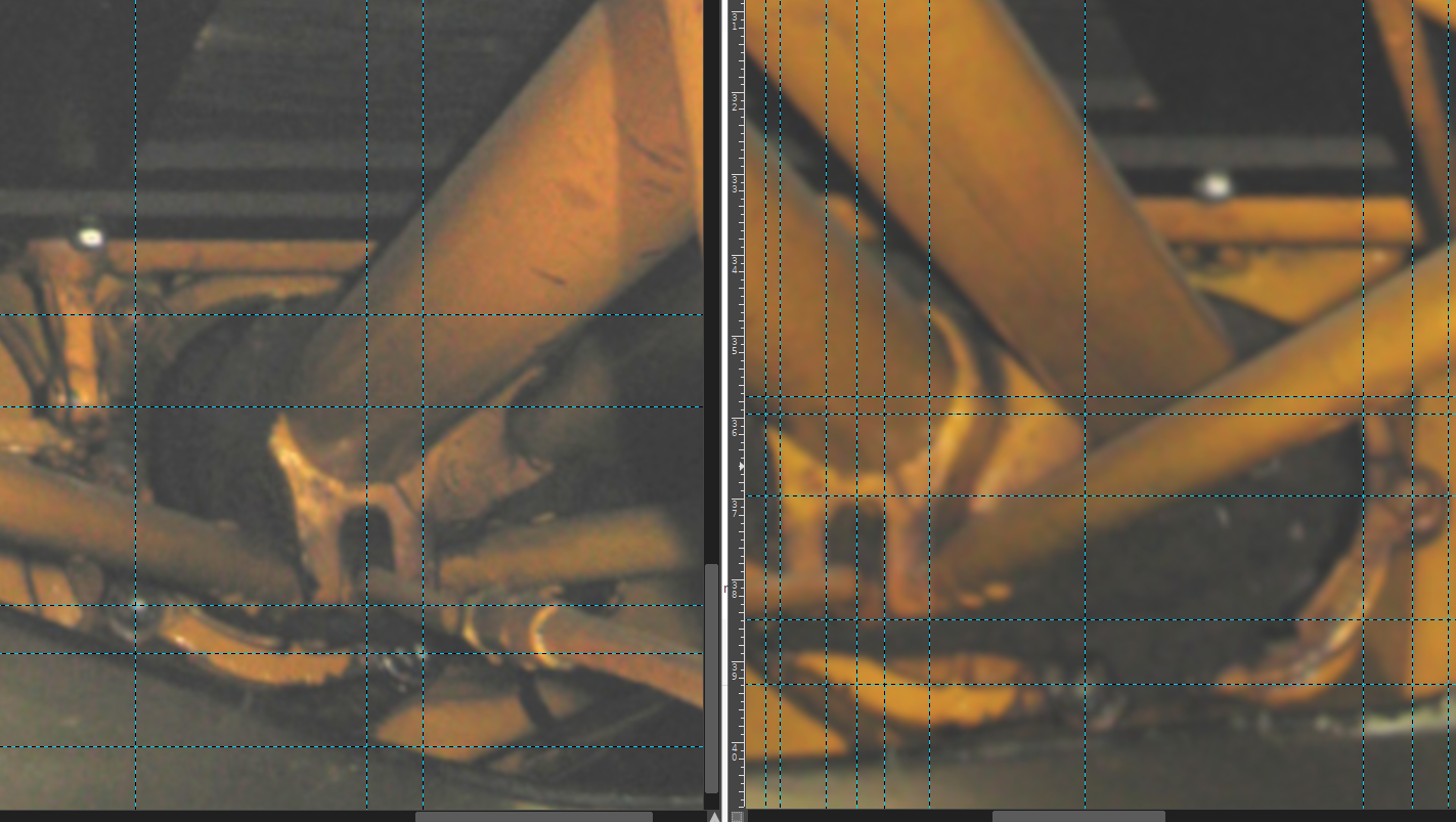
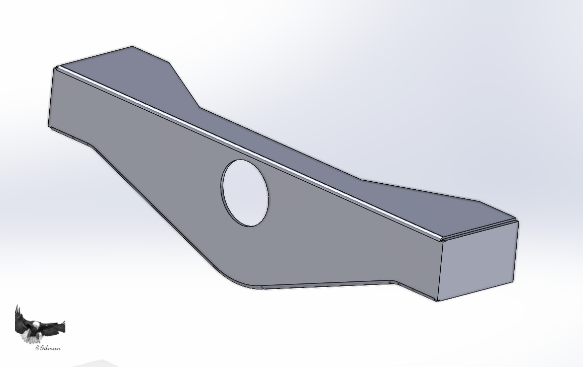
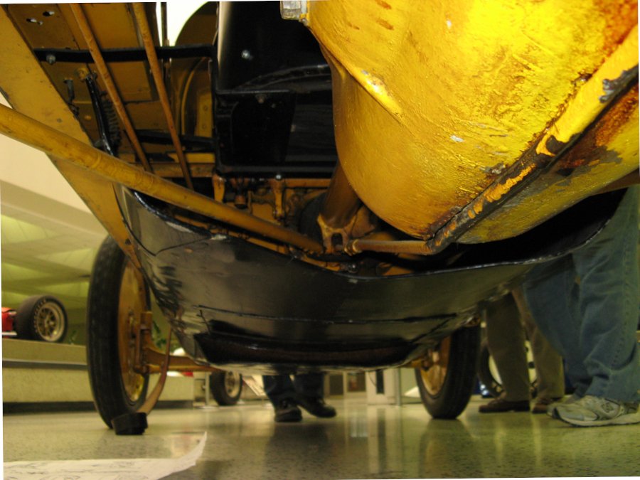
Ok the next step is to look at your images see what is there and where your part is going to reside... The shot on the left is showing the right side of the Thrust Crossmember, the pic on the right is showing the left side... This was my current Crossmember.... You notice it has a flat on the bottom that shouldn't be there.... In the first two pics you can see the lower edges of the cross member on the opposite sides adjacent to the Thrust collar and almost beneath it... The angles of those sections are telling me that there isn't a flat on the bottom of the cross member.. It is round.... So, we check the historical images for proof.... Below are two from race day... You can clearly see it behind the flywheel hanging down a few inches.... Now with the ability to measure the images the left edge is about 5.5 inches from the tube center, and the right edge is 6.5 inches from the tube center in it's pic... That is the effect of proportion on the image two differing camera angles as well... so what I do is take the average of the distances which is 6 inches and redraw the Crossmember to reflect what is actually on the car... And here it is on the chassis, yeah it seems to be hanging a bit low so I'll probably have to go back and adjust it a bit... But this is a good reminder to not limit yourself to just the part you want to model there is a lot of information in the rest of the picture about the parts environment that helps to set the limitations of the design... This process is one of design, adjust the design, add more adjust again, add a little more adjust again... and so on and so forth... A constant process of adjustment... That's all for now... Will continue... EG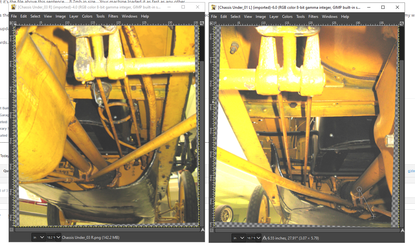

-
Keeping my head in the game.....
Egilman replied to Egilman's topic in 3D-Printing and Laser-Cutting.
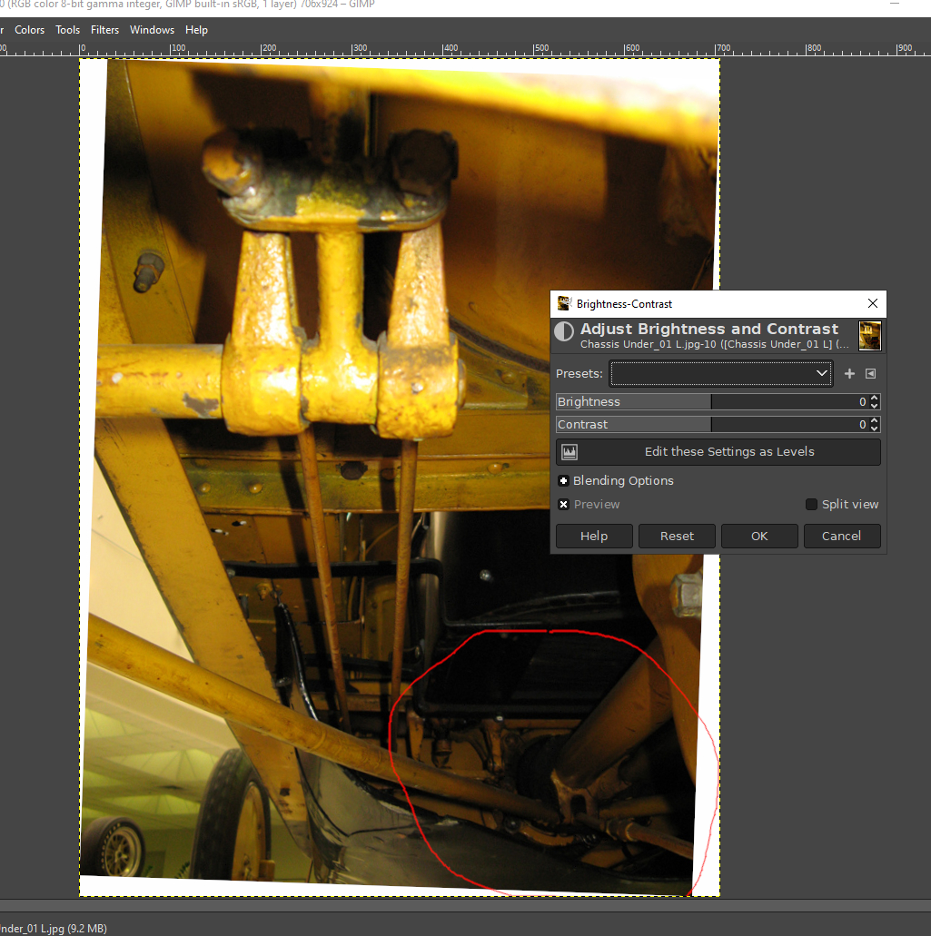
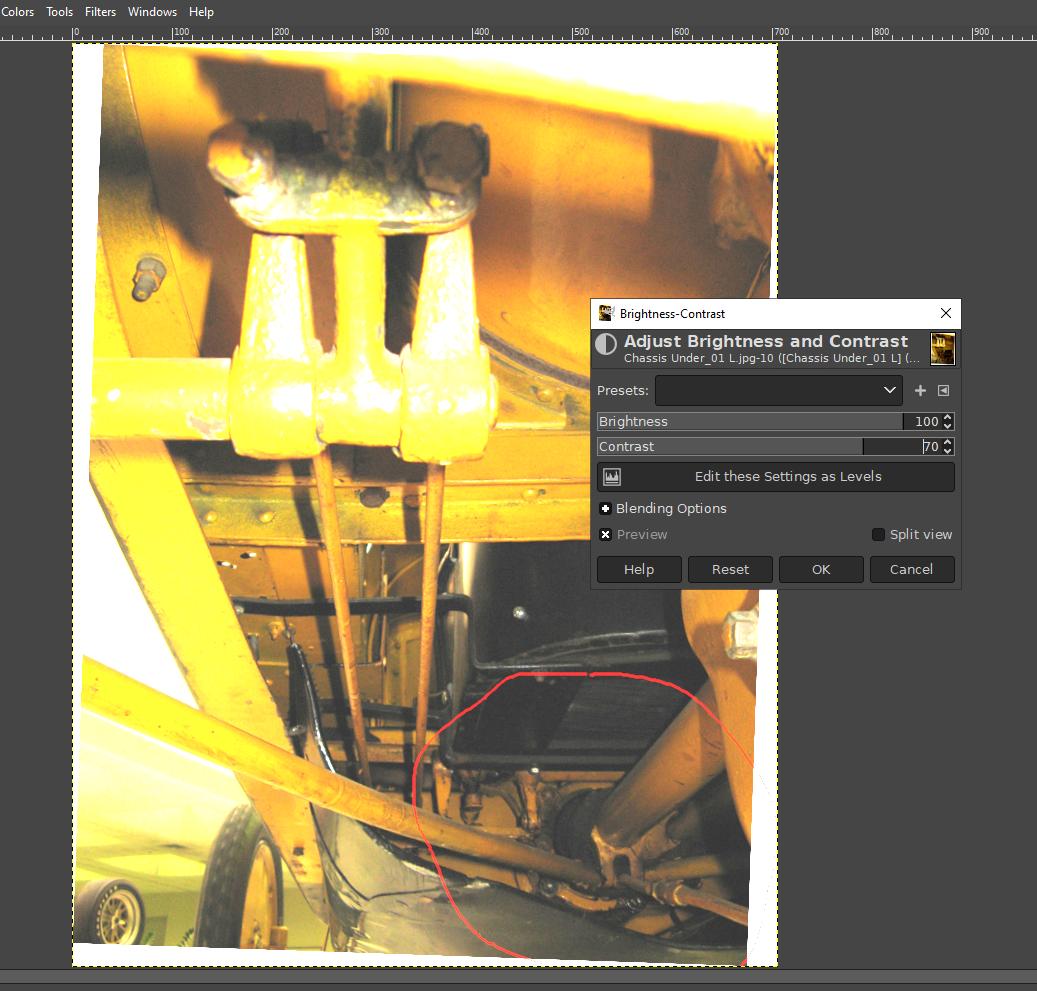
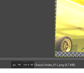
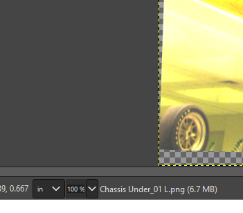
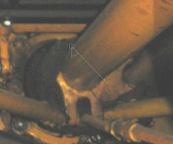
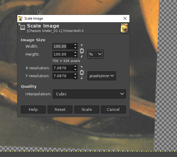
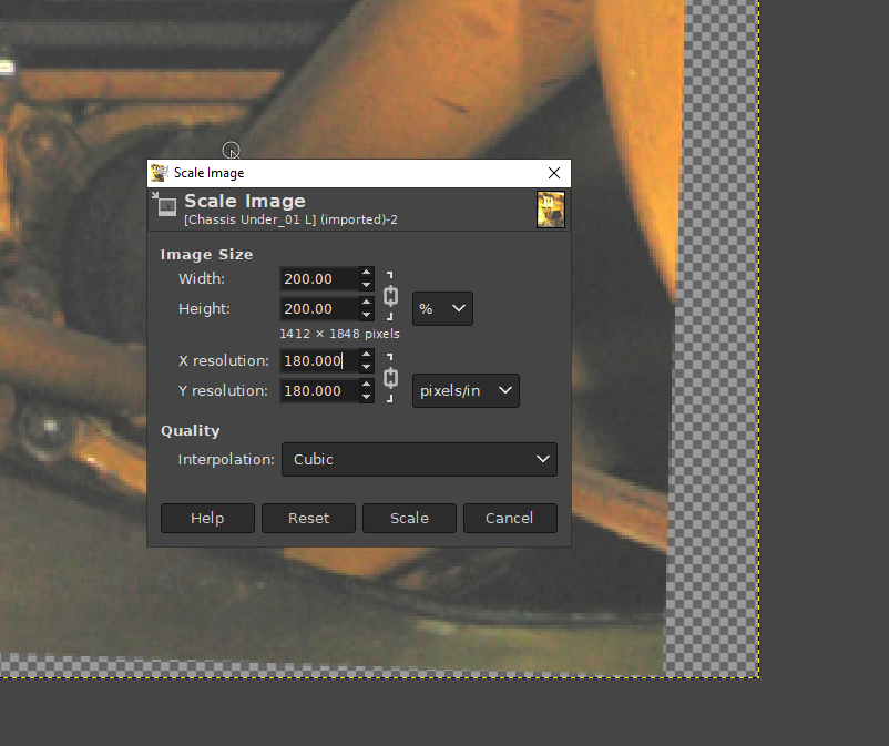
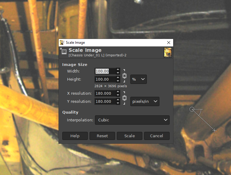
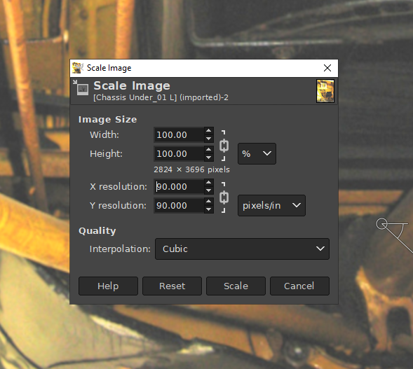
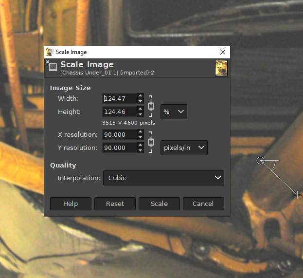
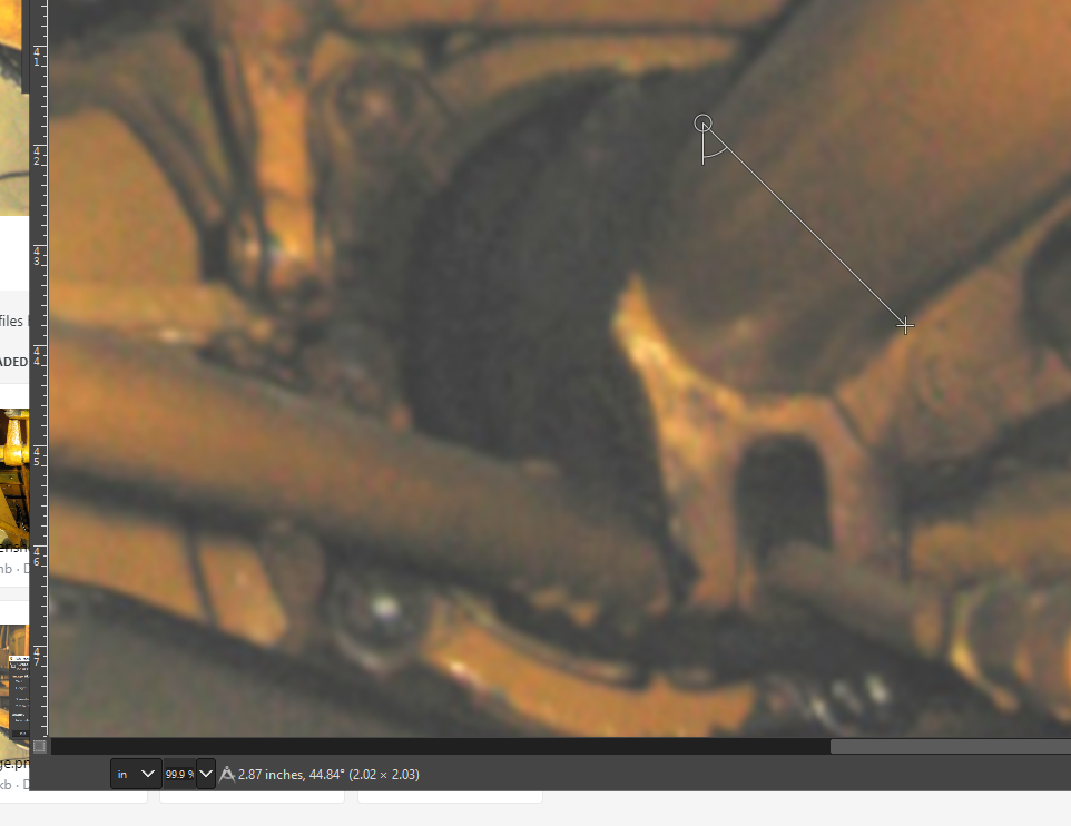
Here we go... The first two images I posted have already been processed in gimp and are ready for use, the last to images have not been completely processed and for all intents are still raw.... That's why they look dark, especially around the area we want to model.... So we will process those two first.... I use Gimp for image processing, I also have Photoshop but prefer Gimp simply cause I'm more familiar with it... (in essence they are identical in capabilities) How you go about fixing an image for this type of work is fairly quick and easy.... We open the image in Gimp.... The part we want to model is circled in the lower right corner... Very dark, you can hardly see it much less measure it... So we need to lighten and brighten it so we can see what is there.... Under the Colors menu we select Brightness and Contrast... (Quick and dirty color correcting) For most normal pics I take the brightness up to 80 and the contrast up to 40, this usually brightens the picture enough to bring out the details, but this pic is so dark I'm going to 100 on brightness and 70 on contrast... And select OK, now we can see what we are looking at... Next step is to scale it... so we have picked a section of the pic we wish to measure so we need to scale in that region of the pic... Cameras take pictures in perspective so items in the foreground will ALWAYS be larger than objects in the background.... we are going to scale the background in the location of the thrust collar... when done we will be able to measure and get approximate dimensions of objects in that (depth) area of the pic... Anything closer will not be correct, anything farther away will also not be correct... We are only working in the part of the image we need forget the rest... This is the image I previously corrected... And the one I will be taking measurements of.... We are going to scale it at the Collar around the Thrust Tube which measures 2 7/8" on the full sized model.... So we switch the image reporting in the taskbar at the bottom to report inches.... We switch from pixels to inches, (or mm's if that is your chosen measure) this is so what ever we use the measure tool on reports the length of what we measure... we know the outside diameter of the thrust tube is 2 7/8ths inches, we now wish to make the image distance the same... For this we use the measure tool, it looks like a pair of dividers on the tool palette we use those to measure across the Tube in the image where it connects to the thrust collar... At the bottom left corner we see that this section of the image measures .295 inches.. now it's simple math we need 2.875 inches and we have ,295 you divide what you need by what you have to get the percent you either need to enlarge or reduce the image... 974.58 % enlargement.... That's a pretty hefty jump in size isn't it? how we gonna do that without destroying the image? Simple we use the percentage scale function and the pixel scale function... But the order we use them in is critical to keeping a useable measurable file. the main thing with enlarging images is not damaging the pixels size ratio nor do you want to create more pixels either... This is done by creating larger pixels this is what the scale by percent function does... So you increase in steps I call this the by 200's method,,, we do increase the size maintaining the aspect ration of the image by 200% and then measure again... And we measure the same spot again and find we have doubled the measured size... I get .581 inches... so we need another step up in scale we do the by the 200's again.... And this time you see the scale function was quick, but noticeably slower than before, this is a polite reminder from Gimp that you can only go so far before you make a file you can't load... I get 1.156 inches for the measurement... We need another bump before final sizing.... But how do we go about this without increasing the file size? Simple we reduce the pixel resolution.... When we execute this the change is instantaneous, cause what we are changing is the way the image displays on the screen we are not changing the physical size of the image... I now measure the thrust tube in the same place as before and we get 2.31 inches... We have now arrived at our scale neighborhood we just have to make the final scale.... 2.875 / 2.31 = 124.46% enlargement.... a fairly small step up... Let the software choose what it wants for pixel scaling you put in the calculated scale and the number coming back is what the images pixel scale will allow, just accept if and let Gimp work... It may warn you that you are creating a large image file and that is ok it's not going to be too large accept it... it also may screen pause in creating the file, this is ok as well... let it do it's thing... when it's done you will have this.... An image where the measured size of the thrust tube at the thrust collar is 2.875 inches in diameter, exactly what we needed... The resulting file is not that large, it's fast loading and won't stuff your harddrive with bits... In fact it's the file above this sentence.... 8.7mb in size... Your machine loaded it as fast as any other... This is the conclusion to the scaling steps repeat for the rest of the files your going to use... This is a simple technique that doesn't bury you in bits... I'm sure there are other ways people will do this, this is just my way, it works for me... Next update will show you how we extract the measurements as we go to model the part... Onwards.. EG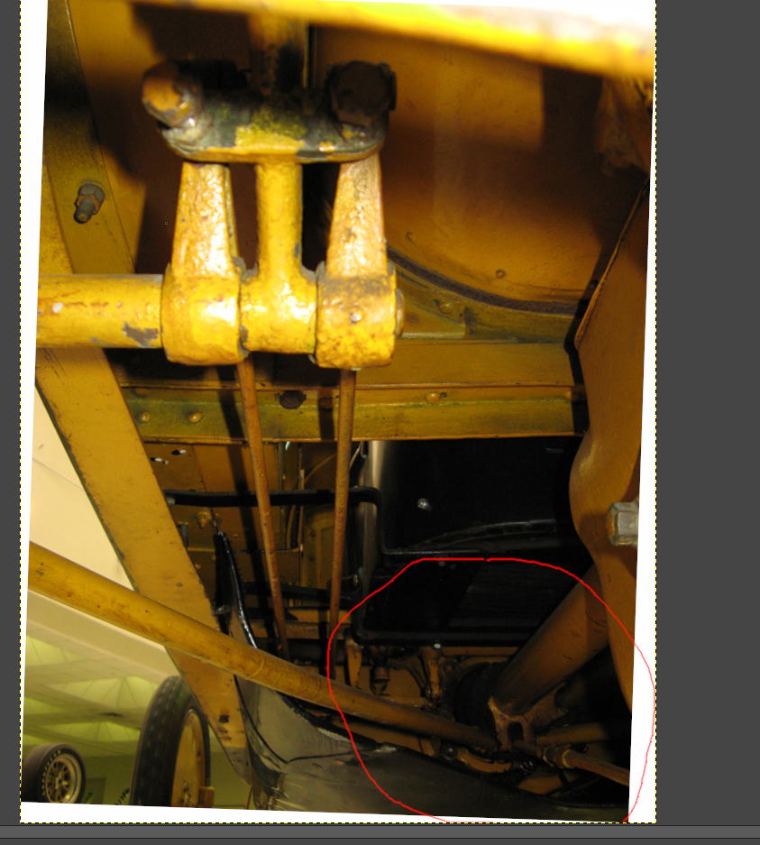


-
Keeping my head in the game.....
Egilman replied to Egilman's topic in 3D-Printing and Laser-Cutting.
Thank you James, I hope it's going to help people get a better understanding in how the various technologies are coming together to revolutionize our hobby... This is only the first step in the process.... -
Yep I've read the same things, but the best results I achieved was with Formula 560, a specific glue for micro thin canopies works very well on the kit canopies as well... It usually take one application as it shrinks to completely invisible level and the bond is something to believe.... Not that Micro clear won't work cause it does, it's just that there are other products that work even better in some circumstances... This is one of them...
-
Keeping my head in the game.....
Egilman replied to Egilman's topic in 3D-Printing and Laser-Cutting.
Ok this update is going to be a step by step of the process of designing a mechanical part in 3D from just a few photographs... We start with the Images... The first is a picture of the top of the frame... It has been adjusted in gimp to measure out to full size, 115.5" wheelbase and 56.5" track at the rear wheels and straightened as much as possible for a distorted scanner image... The second is a picture taken at the IMS museum of the actual Wasp... From the right side, underneath looking forward towards the Thrust Crossmember.... The third pic is the same as the second except from the left side.... And the fourth is also from the left side but at a different angle.... All of these pics are of sufficient quality to be adjustable to full size so we can take measurements... Now I already have figured out the measurements I need for the adjustment... With the frame image at full size I take off the thrust tube diameter and it is the known common feature in the other pics... The process we are going to be using to create the basis of our part and get the dimensions we need is called Photogrammetry... Today Photogrammetry has it software packages just like everything else, But I've been doing it long before there were computers to either assist or baffle us in the minutia of perfection... those software packages have been around a while and make 3D modeling relatively easy if you want to learn the process, the problem is you need images, LOTS of them of the subject your going to model... Unfortunately we don't have lots of images, only a few of unknown quality and differing composition... So we go back to the old school way of rulers and calculators... Except we can use the computer for the sizing and measuring... So I guess the old school process has evolved a bit as well... Now most of my images have already been resized to full size for the info I want to get but I do have one where I will demonstrate the process... And hopefully give everyone a better understanding of what is taking place... I chose this part cause it is the one part where I have only a few images and incomplete coverage of that part I will have to derive a lot from what is happening in the image and take into consideration all the info in the images... It is said that a picture is worth a thousand words... We are going to see if this is true.... More later my friends.... Onwards...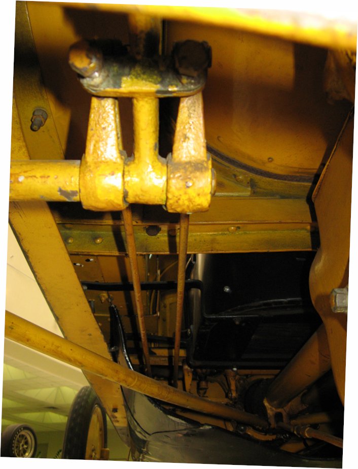


-
Keeping my head in the game.....
Egilman replied to Egilman's topic in 3D-Printing and Laser-Cutting.
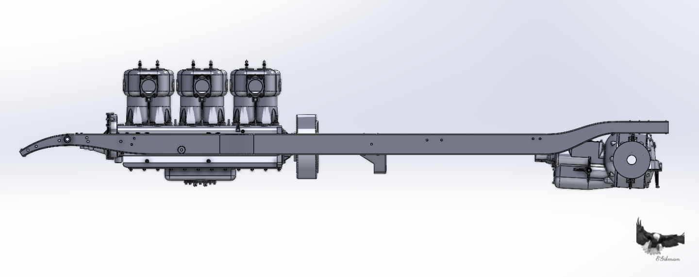
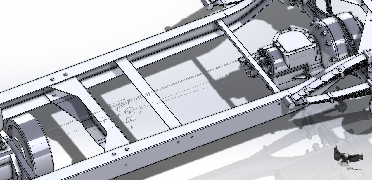
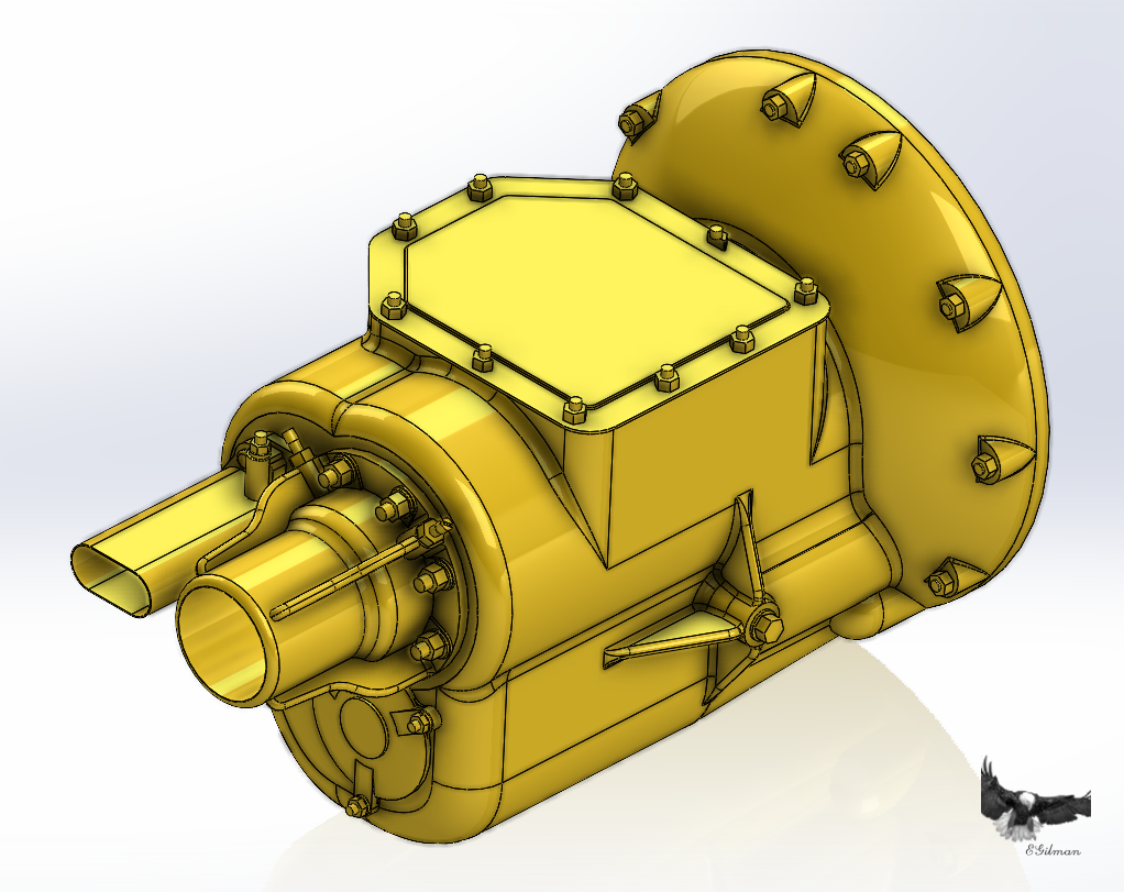
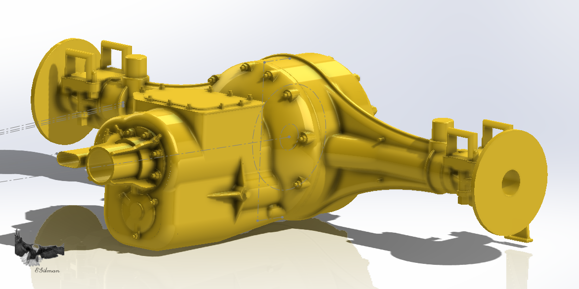
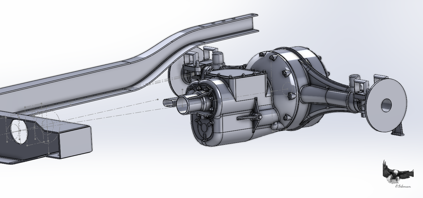
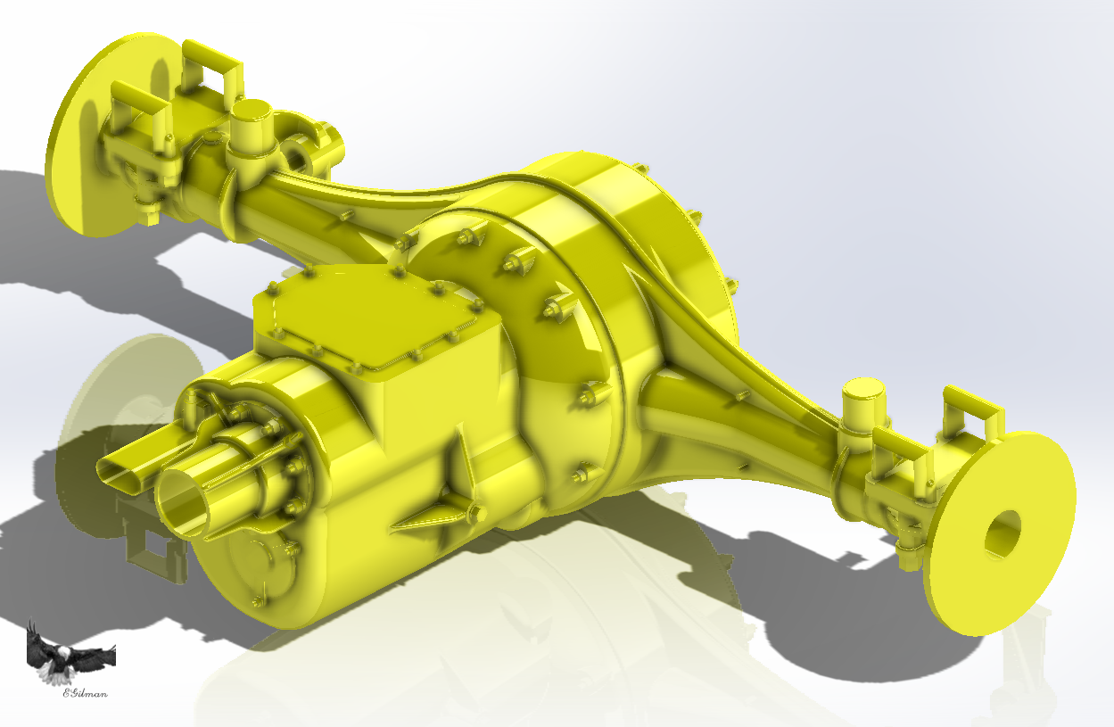
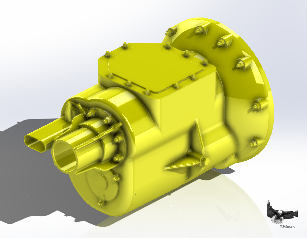
Another update.... Getting ready for the design of the Thrust Collar... it mounts to the Thrust Crossmember and receives the Thrust Tube from the Rear End.... The Transmission is connected to the thrust tube and all the parts need to align accurately.... To this end I drew an engineering sketch of the locations and alignments of all the pieces, it looks like this... The three lines across the top are the top flange of the right frame rail... The lower horizontal line represents the clutch/engine output shaft line.... The vertical line represents the flange side of the thrust crossmember and the circle behind it is the first universal joint... Then there is the box that pops up above the floorline in the cockpit, it has the cross shaft of the shifter and emergency brake which is represented by the small circle on the box's centerline....The next feature is the large circle, it represents the thrust head that resides in the thrust collar, inside it is the circle for the second universal joint and the vertical center line is the split line between the collars socket and it's retaining cover... Between the centers of the two universals is the transfer shaft, a short driveshaft to allow the driveline to flex into the suspension pivot point the second universal sited at the suspension flex point... Behind that we have the driveline/thrust tube centerline which runs thru the transmission to the Differential center... The large circle represents the Rear Axle flanges and the right brace represents the Differential case perpendicular to the driveline centerline the transmission will be to the left of the brace with the Differential Housing setting the angle of the transmission... I know it's sparse, but it has all the info I need to set it up accurately... I also set up an index point matched to the models origination point in the software, so no matter which drawing I drop it into, it will be in the same place, (model space) on all of them... This is what it looks like... With this you can readily see that the Tranny is too high and at the wrong angle... The angle problem comes from the Differential Housing rotated too far back and is causing the Transmission to be too high... So, the first step is to correct the Differential Housing's problem, the second step is rebuild the tranny so it matches both the Differential housing mating surface and so the driveline centerline enters the center of the Thrust tube collar on the front of the tranny.. The Differential housing was a snap... took maybe an hour to correct.... The Tranny took four days and three rebuilds... I finally ended up with this... Looking it over for the last day, there isn't much that can be corrected or re-shaped, it looks like it's pictures and feels right... I'm calling it done... I figure about 97-98% accurate to the real thing.... Here is what it looks like with the Rear Axle.... And here you see it with the Alignment sketch... Here's a better look at it in the frame.... You can't get any better alignment than that... That was a lot of work... Almost ten hours a day except for the normal interruptions of the day... I think it looks kinda good, It fits... More detail takes more work.... {chuckle} Anyway this is where I'm at now, ready to start the Thrust Collar design...... (and give you guys a view into what this kind of modeling work involves) EG Onwards!!!! Ubiquetous overall shot....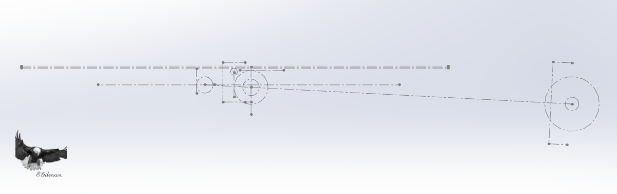

- 85 replies
-
- 11
-

-

-
Triumph 3HW by Tim Moore - Italeri - 1/9
Egilman replied to Tim Moore's topic in Non-ship/categorised builds
It's also an application of the Lever in the round.... All wheels are... But that's an aside... Yes your suspended on the few spokes on the tops of the rims... The spokes at the rear of the front wheel drag the front wheel from the axle at the same time every where it goes as well, and the rear wheel is drug by the axle as well with a slight bit of differing physical forces acting on it... Structural strength is maintained by stressing the wire spokes in tension, Adjusting a wire spoked wheel is just about a lost art today... And if I remember correct the lacing of the spokes is just as important to power transmission as it is for structural strength.... There a lot of practical tech out there that's being left behind as engineering advances... -
Wow the 9.85" heavy mortar, choice of short or long barreled versions as well.... That would be a heck of a piece for it's own depiction brother....
-
Now this is what modeling is all about.... She looks real, a captured moment in time... Dawn Patrol; Just departing Scapa into the North Sea, the sea state is changing into the rolling waves of the open ocean which are beginning to overpower the relatively sheltered water of the anchorage channel..... Several patrols done going out for another... Appropriate rust with fading and failing camo paint... The only thing left is imagining the impossible to model fog.... You need to get close to see her wear and tear, from a distance she looks well apportioned, ready for anything, an imposing force ready to meet it's destiny... Getting ready to signal the rest of the squadron..... This is on the extreme end of well done brother.... Superlative in everyway.... A contest winner for sure....
-
B-25J Mitchell by Chadwijm6 - HK Models - 1/32
Egilman replied to chadwijm6's topic in Non-ship/categorised builds
Beautiful, with one exception, the front reduction gear cover should be grey... (your pics will give you the color) They were painted that way, (every single one) on the production line before they were ever shipped.... -
F-14D Super Tomcat by CDW - AMK - 1:48 Scale
Egilman replied to CDW's topic in Non-ship/categorised builds
Yep definitely read both pages... The info is pure gold... Also that's the place to ask those questions... The general idea is that given the mission and what was on hand munitions wise, they could have carried anything within the aircraft's approved spec config, any day of the week... The full range of munitions was available... The best bet is to look at combat pics for specific aircraft... (which is typical for any model carrying external ordinance) You have the decals for VF-31 Tomcatters, off the USS Lincoln, one of the three carriers operating in the Persian Gulf over Afghanistan & Iraq during OEF, OSW & OIF 2002-03.... -
F-14D Super Tomcat by CDW - AMK - 1:48 Scale
Egilman replied to CDW's topic in Non-ship/categorised builds
Here ya go... http://www.arcforums.com/forums/air/index.php?/topic/221470-f-14-tomcat-weaponry-config/ Covers typical air to air and some fairly standard OIF (Operation Iraqi Freedom) loadouts... The weapons that come with the kit puts you right into that OIF & OEF time frame... Hope it helps... -
Keeping my head in the game.....
Egilman replied to Egilman's topic in 3D-Printing and Laser-Cutting.
Yep, this was still the era of open air tapered clutches, they had just began using universal joints to transmit power so the only place the Tranny could go was in front of the Differential.... You see a lot of people use the 20th/21st century term Transaxle for this but it wasn't that at all, there is no mechanical connection between the two, the differential can be completely disassembled without touching the tranny... When they perfected the disc clutch, that's when the engineering concept changed, a flat thin flywheel with a thin clutch plate allowed the creation of the bell housing which acted as the mount for the Transmission and removed the need for rear engine mounts... It also reversed the method of mounting to two points forward and one point rear... (usually at the end of the Tranny, the system still in use today) This made the Engine Clutch and Tranny one single assembly which made manufacturing even more efficient.... One of the residuals from the system this car has is the thrust bearing with it's integral universal joint in the middle of the frame became the carrier bearing along with the split driveline with the rear suspension pivot point remaining the same clear into the late '50's early 60's... (where we still saw it on the light trucks of the era and eventually lead into the two link coil spring rear suspension we saw on the 60's/70's chevy pickup trucks) So many of the features of this car carried long into the future of the automobile and didn't really disappear until the early 2000's..... She was state of the art in her day.... -
One of the most beautiful model airplanes I've ever seen, any era... Well done....
-
AMC DH9 by davec - FINISHED - Wingnut Wings - 1/32
Egilman replied to davec's topic in Non-ship/categorised builds
IT's RED!!!! Wow fantastic job... Red isn't a great color to go overall with but you've done it justice... Well done.... -
F-14D Super Tomcat by CDW - AMK - 1:48 Scale
Egilman replied to CDW's topic in Non-ship/categorised builds
Back in the '90's I had a model room in my previous home 14'x10' it had two shelves that went around the walls completely just above the door line... On those shelves I had every single one of Monograms 1/48 scale lineup... (add in a few of Revell's as well) The jets definitely take up a LOT of room.... Almost as much as the B-24 & B-17.... -
Keeping my head in the game.....
Egilman replied to Egilman's topic in 3D-Printing and Laser-Cutting.
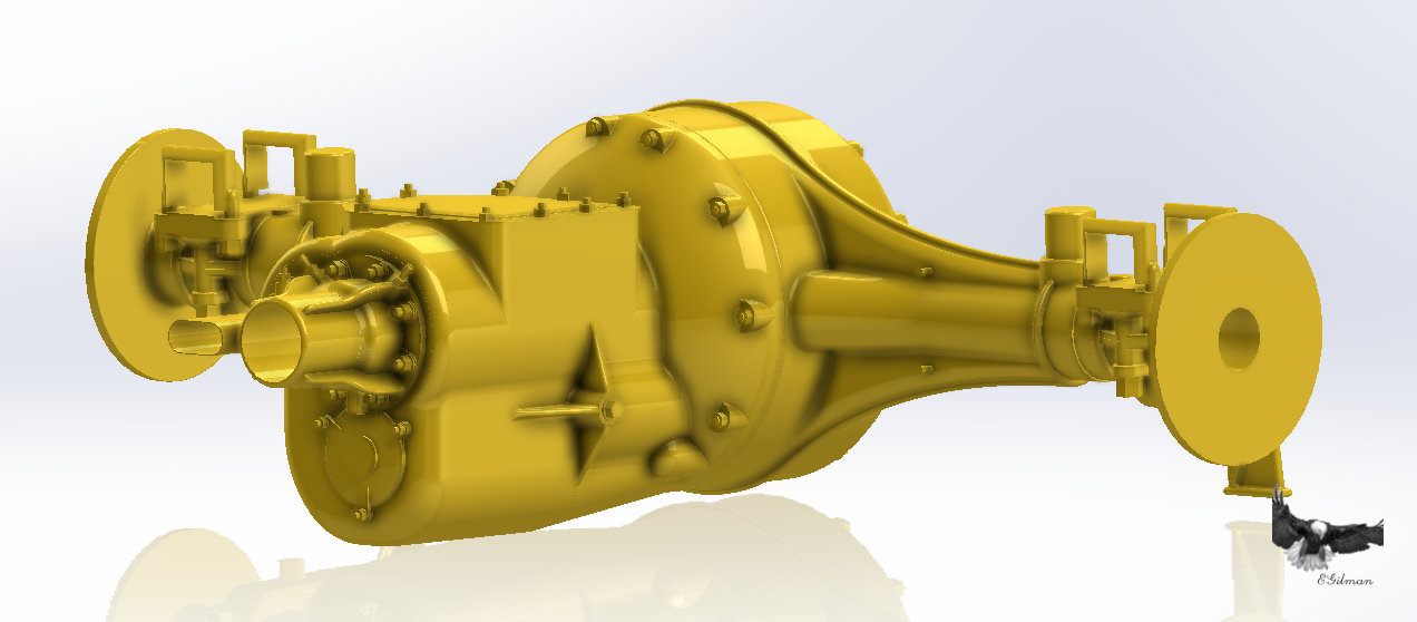
Well, I've gotten the Transmission to where I'm going to call it done.... Might still need some tweaking as other parts are added... But we will do those if any when we get there... Here is what she looks like... And with the axle/differential.... The yellow is for glamor purposes... {chuckle} In the frame... I would say she is 95% accurate, there were still a few spots without enough coverage to be sure, but a lot of hints to what had to be there... Anyway I'm calling it done for now... And the usual overall shot... Onwards!!!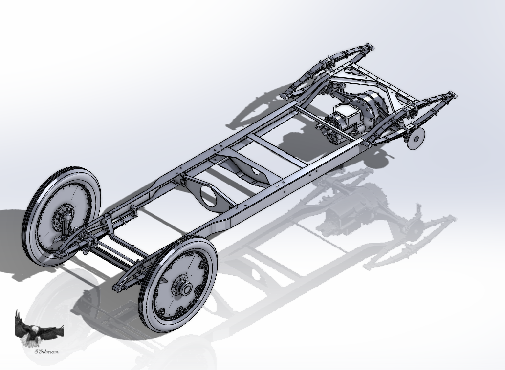
-
Yep, that happens all too often.... Good that you found it...
-
B-25J Mitchell by Chadwijm6 - HK Models - 1/32
Egilman replied to chadwijm6's topic in Non-ship/categorised builds
Wow, that hs made up my mind, I won't be buying AM for mine then,, those kit engines look great... -
B-25J Mitchell by Chadwijm6 - HK Models - 1/32
Egilman replied to chadwijm6's topic in Non-ship/categorised builds
If those are your aftermarkets they look very good.... Nice paintwork.... -
B-25J Mitchell by Chadwijm6 - HK Models - 1/32
Egilman replied to chadwijm6's topic in Non-ship/categorised builds
You have a PN brother....