


Papa
-
Posts
1,298 -
Joined
-
Last visited
Reputation Activity
-

 Papa got a reaction from GrandpaPhil in Chaperon by Papa - FINISHED - Model Shipways - Ron Gove
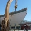
Well, Finished At Last! Just need to make a base. I apologize for all the clutter in the photos
-
 Papa got a reaction from Canute in Bismarck by Dan Vadas - FINISHED - GPM - 1:200 - CARD and PE
Dan,
your work is simply amazing.
-
 Papa got a reaction from mtaylor in Bismarck by Dan Vadas - FINISHED - GPM - 1:200 - CARD and PE
Dan,
your work is simply amazing.
-
 Papa got a reaction from Landlocked123 in Bismarck by Dan Vadas - FINISHED - GPM - 1:200 - CARD and PE
Dan,
your work is simply amazing.
-
 Papa got a reaction from robdurant in Bismarck by Dan Vadas - FINISHED - GPM - 1:200 - CARD and PE
Dan,
your work is simply amazing.
-
 Papa got a reaction from popeye the sailor in Bismarck by Dan Vadas - FINISHED - GPM - 1:200 - CARD and PE
Dan,
your work is simply amazing.
-
 Papa got a reaction from Dan Vadas in Bismarck by Dan Vadas - FINISHED - GPM - 1:200 - CARD and PE
Dan,
your work is simply amazing.
-
 Papa reacted to Dan Vadas in Bismarck by Dan Vadas - FINISHED - GPM - 1:200 - CARD and PE
Thanks very much Nils and Popeye .
After looking at the pics of the main mast I got the feeling that I'd used the wrong spar for the longer lower one. Sure enough, wrong part number . I carefully removed the one fitted using a new scalpel blade to cut through the CA glue. It came off with no more damage than a bit of lost paint :
I fitted the footrail to the right spar and reattached it :
That looks a lot more like it :
Danny
-
Papa reacted to Dan Vadas in Bismarck by Dan Vadas - FINISHED - GPM - 1:200 - CARD and PE
There are a total of 13 Ship's Boats of various types to be built. I needed to make and fit four Motor Launches to continue with the Aft Superstructure. I figured it would be rather difficult to fit them later on, and I was proved right - it was hard enough to fit them without anything else in the way. It would have been nearly impossible to do a good job of it once the mast and platform were in the way.
The kit supplies a rudimentary laser-cut framing for the hull, consisting of two pieces. I added more card to them to prevent any crushing as the hull was skinned :
Here are the pieces for these four launches :
I cut out the middle of the decks :
And most of the pieces for one launch cut out :
Assembly starts by gluing the flooring underneath the deck. This was then glued to the framing, and the transom was also added :
I shaped the hull skins with a rounded stick on my piece of high-density foam :
Next one skin was glued to the edge of the deck :
The aft end of the lower hull was then glued on, then the bow section, finishing off with the two middle areas. The fit of the sides was very good :
The four hulls skinned. You can see the improvement in my technique - the first one I did is on the left, the last on the right. All are acceptable however, as the boat racks hide the worst joins :
Now I folded and fitted the cabin. That sounds easy when you say it fast, in reality they took me half a day to do :
The finishing touches included two railings on the fore deck, a rudder, a propellor shaft and the tiny (2.5mm) propellor from the PE set :
The four launches fitted to the main hangar. I had a lot of trouble with the racks for the two middle boats, having to cut the central ones down about 1mm and removing, trimming and refitting the fore ones further aft. That's what happens when you trust the kit to have things in the right positions, only to be let down once again . The middle boats aren't fitted crooked, that is the way they have to fit to clear the mast platform :
Danny
-
Papa reacted to Dan Vadas in Bismarck by Dan Vadas - FINISHED - GPM - 1:200 - CARD and PE
Now that we're back on line at last I can put in an update. There are two boat racks either side of the main hangar, similar to the ones I built for the other hangars. These have turned out a lot better than the first ones - something to do with gaining more experience perhaps :
The main hangar with all the racks fitted :
Next up is a platform at the bottom of the main mast. The design of this was a bit ordinary (no - a LOT ordinary) to say the least. Why they thought it was a good idea to make the join in the middle of one of the support legs is beyond me, but I'm starting to think that there may have been a lot of Slivovitz consumed at the time . I decided it might be a good idea to make extra support angles for the inside of the legs - the single-thickness paper wanted to crumple at the slightest touch :
I also made gussets to strengthen the tops of the legs, and wicked some CA down the full legth of them. They can now support a VW beetle (almost ) :
The finished platform :
Danny
-
Papa reacted to dziadek4444 in VASA by dziadek4444 - DeAgostini - 1:65
Przepraszam za słaby angielski
Vasa DeAgostini, skala 1:65, wydanie polskie.
Obecnie pracuję nad etapem 50 - 55 kolekcji.
Kilka zdjęć z historii budowy modelu.
-
Papa reacted to captgino in CUX87 Krabbenkutter by captgino - FINISHED - Billing Boats - 1/50
Painting preparation
She decided to go with blue. So here we are...
Black rail.
-
Papa reacted to captgino in CUX87 Krabbenkutter by captgino - FINISHED - Billing Boats - 1/50
Worked on cutting out the scupper.
Attached the Wales and side reinforcement.
-
Papa got a reaction from Canute in SMS Helgoland by Papa - Modelik - 1:200 - CARD
I am totally stuck. Did a lot of Googleing but can't find an image with enough resolution to see what this cabin is suppose to look like. No matter, the wife and I are going to be traveling to warmer weather until April so Helgoland and Granado are going into dry dock for the duration. i will have to focus on reading, drinking wine, and perhaps making sketches of ships.
-
Papa got a reaction from mtaylor in Flying Cloud Voyage of 1851
Those are good points. I am sure that the logs of all the California bound clippers would follow roughly the same route. The experienced captains knew where to find the winds.
Ron
-
 Papa got a reaction from alde in Hobbyzone building slip for wooden ship models
This building slip is really versatile, here I turned the Victory upside down to get at the stern. I do need to replace the bolts with thumb screws or knurled ends to speed up changing things
-
Papa reacted to Tom Schongar in USS Constitution by Tom Schongar - Model Shipways
Cut out all the bulkheads, marked reference line and bevel lines. Now i just have to sand the bevels ,and the slots to get them all to fit properly.
-
Papa reacted to fnkershner in US Brig Syren by fnkershner - Model Shipways - 1:64
Just a brief Update. thanks to Rich I created a planking Board from some spare Plywood. I also stopped at my local H/W store and picked up some 1/4" tubing. I took the deck layout and screwed some screws covered with sections of tubing and began shaping my Wales. Tonight I plan to thin some MS dull red paint and paint the ports. Tomorrow is Planking!
Note: The 2 screws in the middle are for the shaping of the cap rail for the transom. I will be adding screws later.
-
Papa got a reaction from mtaylor in SMS Helgoland by Papa - Modelik - 1:200 - CARD
looking at the blow up, I now think I see where the stairs go.
-
Papa got a reaction from GrandpaPhil in SMS Helgoland by Papa - Modelik - 1:200 - CARD
I need some help. I got to part 38, which per the instructions is the rear deckhouse. However there is no space on the deck labeled "38". I think it is the white area shown in the photo because the parts sheet has a 38c, and there is a block "c" next to the white space. Also there are 2 parts 58 that are identified by two small circles on 38a, see photo, and also on the deck plan and seems to be in the right general location. And, there is the mast hole in the right place. Now for the quandary. The deck house, part 38, has 6 sides. The white blank space has 8 sides, I've tried 2 different folds and neither makes much sense. There is also supposed to be a line to show where the stairs go, but I don't see it I am thinking that 2 sides were left out of the print. There is some extra grey on the parts sheet that i could cut sides from. Thoughts anyone?
-
Papa got a reaction from Canute in SMS Helgoland by Papa - Modelik - 1:200 - CARD
looking at the blow up, I now think I see where the stairs go.
-
 Papa got a reaction from hexnut in SMS Helgoland by Papa - Modelik - 1:200 - CARD
I need some help. I got to part 38, which per the instructions is the rear deckhouse. However there is no space on the deck labeled "38". I think it is the white area shown in the photo because the parts sheet has a 38c, and there is a block "c" next to the white space. Also there are 2 parts 58 that are identified by two small circles on 38a, see photo, and also on the deck plan and seems to be in the right general location. And, there is the mast hole in the right place. Now for the quandary. The deck house, part 38, has 6 sides. The white blank space has 8 sides, I've tried 2 different folds and neither makes much sense. There is also supposed to be a line to show where the stairs go, but I don't see it I am thinking that 2 sides were left out of the print. There is some extra grey on the parts sheet that i could cut sides from. Thoughts anyone?
-
Papa reacted to bigcreekdad in Dos Amigos by bigcreekdad
More progress. Much of the deck work finished. Aside from the hatch cross slats, the bell, the barrel, and a few parts of the pump are from kit supplied. Know I've said it before, but the wood in this kit, especially the laser pieces are, frankly, crap. Oh well, sometimes it's fun and accomplishing to make pieces yourself.
I remade the rails for the belaying pins as the laser cut piece broke off on the first piece i was drilling an opening for the deadeyes in. I made new ones slightly thicker to add some strength. Great idea, and worked well, and then I dry fitted a kit supplied belaying pin and found it too short (8mm) . Ended up ordering some 12mm walnut pins from model expo (fast service I might add).
The side rails for the chainplates and deadeyes were typical of the wood. It was quite thin, and after drilling the required openings I felt was got to be weak having much purchase on the planking with only glue. What was really needed was a few pins to go into the hull to add to the glue for purchase. However, the kit supplied laser parts were too thin. I made new ones, adding about 50% to the thickness out of cherry. This allowed me to drill holes and add some pins, which worked well.
When I started on the chain plates and deadeyes, again, I found the kit material not to my liking.The wire to fasten around the deadeyes and attaching to the strops was pretty cheap, and the plates themselves I just didn't like (why am I so picky?). I went toYou Tube and found a vid of a guy using black 24 gauge annealed wired for enclosing the deadeyes, and chain used by jewelry makers. Looked interesting. A quick trip to Michaels Crafts and I had the wire and the chain. I had to make the rail opening a bit bigger, but I kinda like this approach. I've attached some pics and would appreciate any comments on them...good or bad.
Finally, after mounting deadeyes on my first rail, it dawned on me that they looked kinda small for this model. It likely doesn't matter much, but I do have larger deadeyes....I've attached a pic of three deadeyes....the smaller is the kit supplied that I mounted. Any thoughts on these?
While this build has been frustrating due to wood and parts quality, and mediocre instructions, it's been fun nonetheless.
-
Papa got a reaction from popeye the sailor in USS Carl Vinson by Wolfman_63 - FINISHED - Trumpeter -1/350 - PLASTIC - Conversion of Nimitz Kit
Truly amazing. This model is a masterpiece!
-
 Papa got a reaction from Mirabell61 in Flying Cloud Voyage of 1851
Here is a comparison of the Flying Cloud 90 day voyage in 1851 with the Andrew Jackson voyage of 89 days in 1859-1860.
Maximum distance in one day:
Flying Cloud 365 miles
Andrew Jackson 414 miles
Average Speed:
Flying Cloud 7.5 knots
Andrew Jackson 7.2 knots
Total Distance traveled:
Flying Cloud 16183 nm
Andrew Jackson 15399 nm
I think the key to Andrew Jackson's better time is that her course was nearly 800 nm shorter.
I am suspect of the funny jog down near Chile. I think the log entry might be in error. I found one clear error near San Francisco (the position was way too far west relative to the previous longitude) that I corrected with interpolation. Also on Dec 26, 28 and 31 Mr Williams, master, did not log any longitude. I estimated the longitudes by interpolating.