Bill97
-
Posts
2,731 -
Joined
-
Last visited
Content Type
Profiles
Forums
Gallery
Events
Everything posted by Bill97
-
Spending my time now making and adding the rigging to the yards (foot ropes, blocks, etc). Of course while working on these my mind is on the future parrals we have previously discussed. I know I am going to need to make them and hopefully rig them with some bit of realism. I have read through the section in Anderson’s book and studied krill4’s diagram above. I also went back to my reference book for the HMS Victory (Longridge’s book). Interesting in the building of the Victory parrals were not used on the fore and main yards. Just the topsail yards and the topgallant yards.
-
Thanks Marc. If anyone would know it would be you. 😊
-
STUDSAIL/STAYSAIL/STUNSAIL Making a command decision here but will be wait to have my mind changed. Reading through Anderson’s Chapter 11, he is not a big fan of these spars on a model ship. According to him history shows they were just coming into use about the time the SR was built. Page 253 he states that he is not at all sure early stunsails dad yards. French drawings show the lower stunsails hoisted by the two corners. I plan to add sails to my model (probably furled) but not stunsails. With that in mind, reading through Anderson’s chapter, and realizing the difficulty of making and attaching the new spars vs the kit plastic, I have decided to leave these spars off of my yards. Your thoughts and/or opinion?
- 1,508 replies
-
- 1
-

-
- Le Soleil Royal
- Heller
- (and 1 more)
-
Thanks Henry.
-
Thanks Marc. Appreciate your compliment.
-
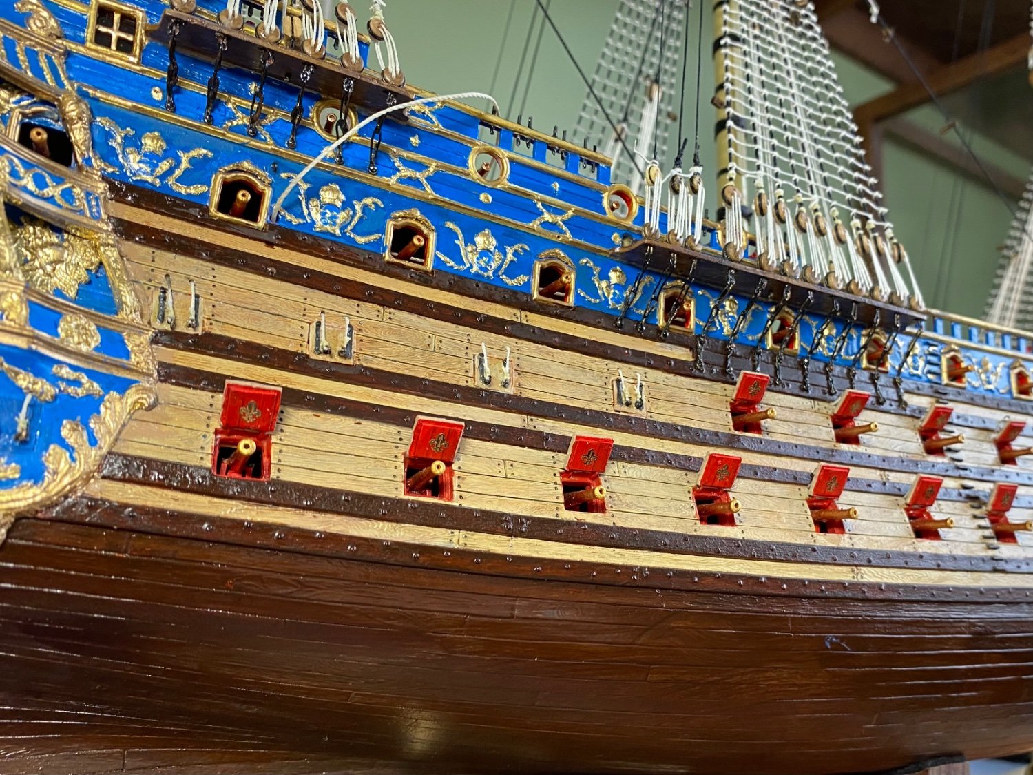
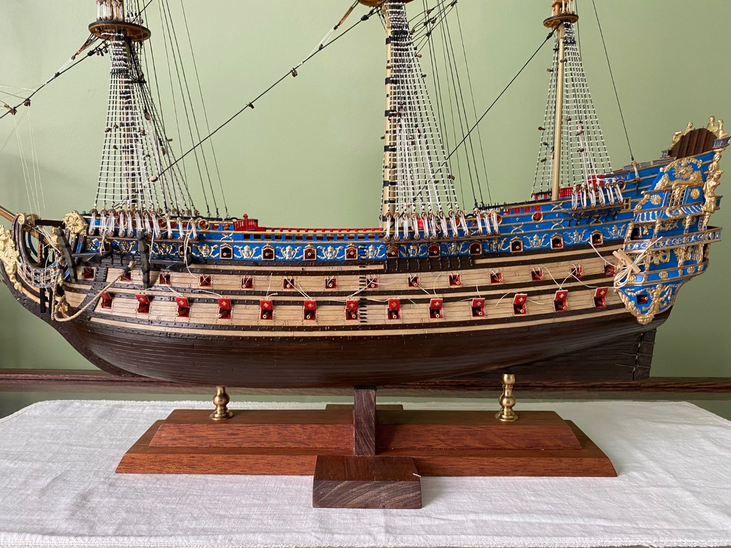
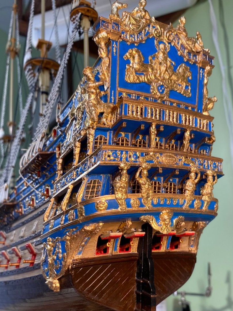
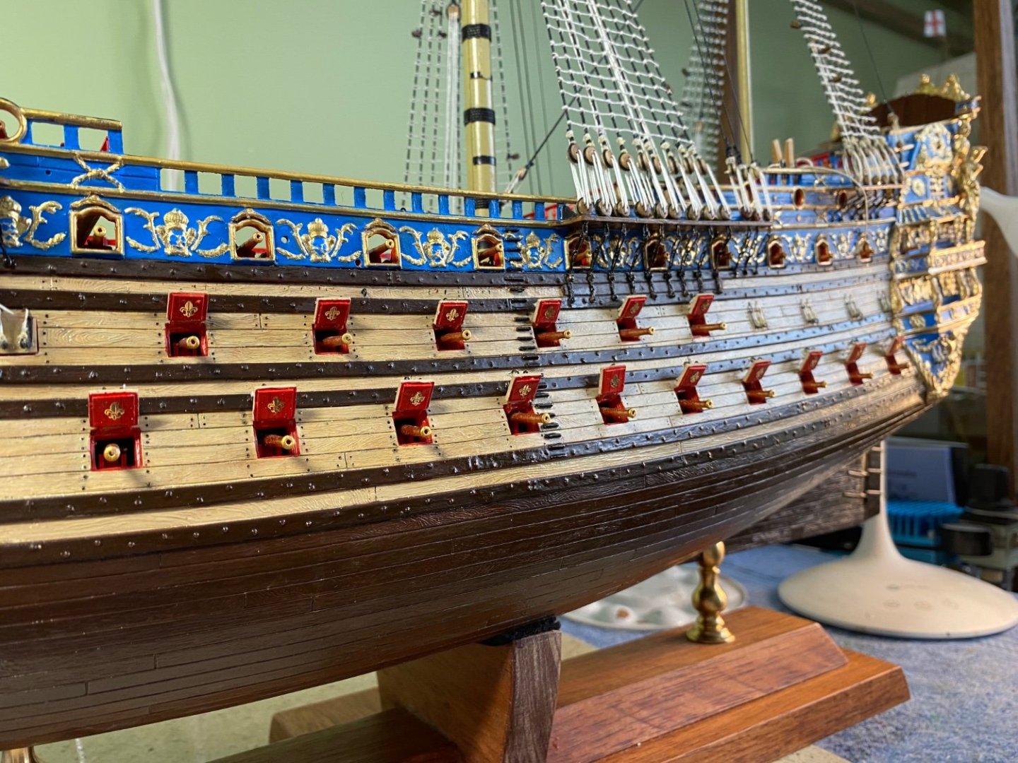
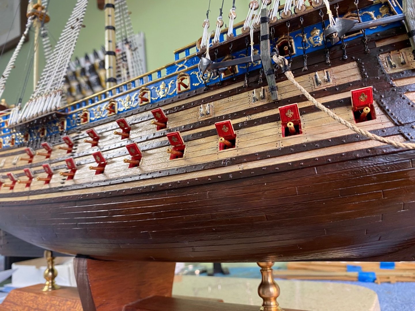
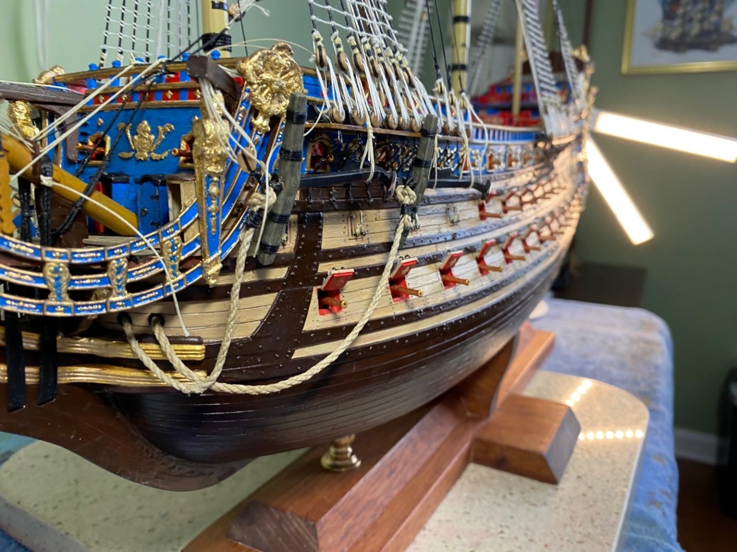
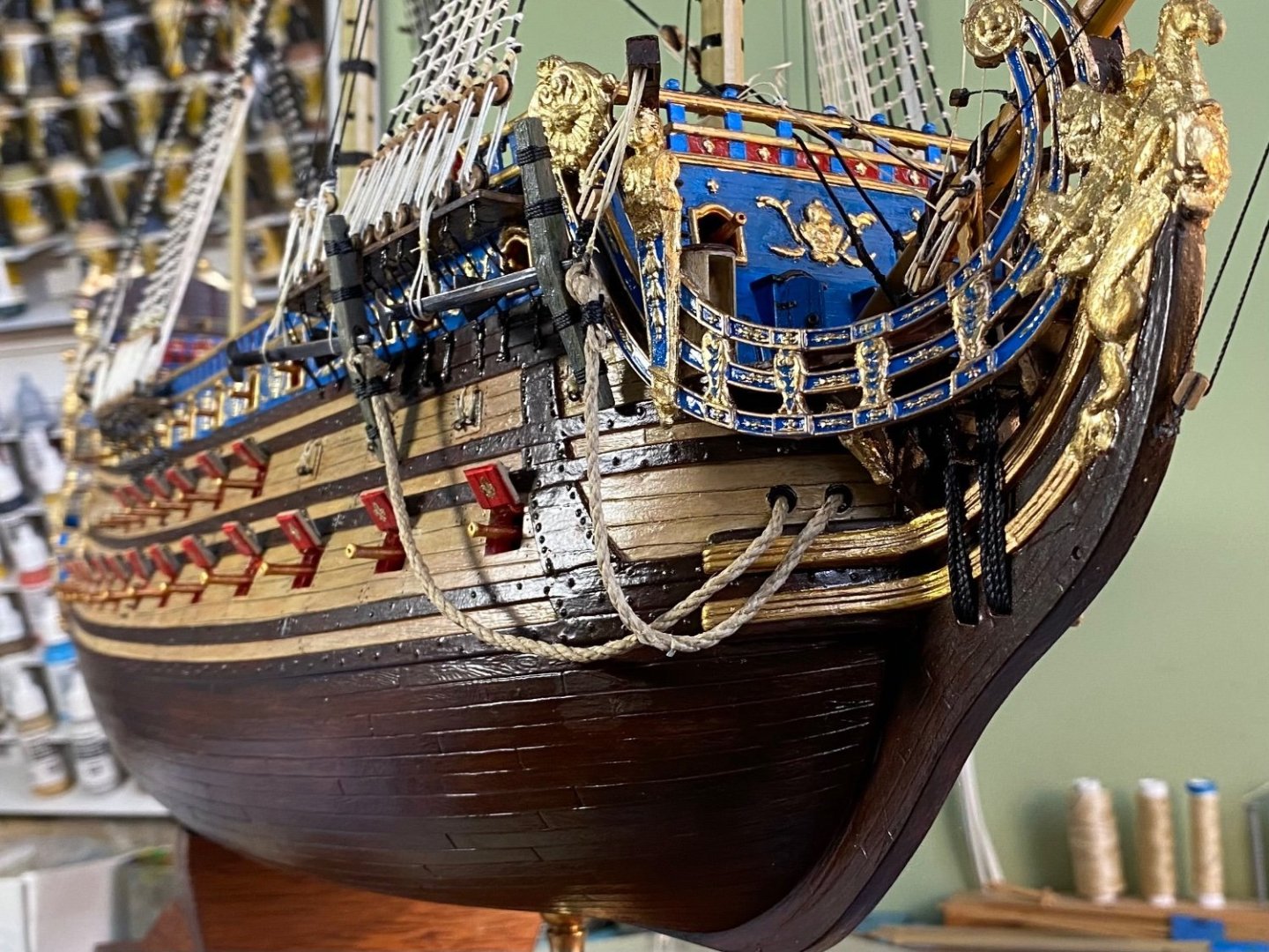
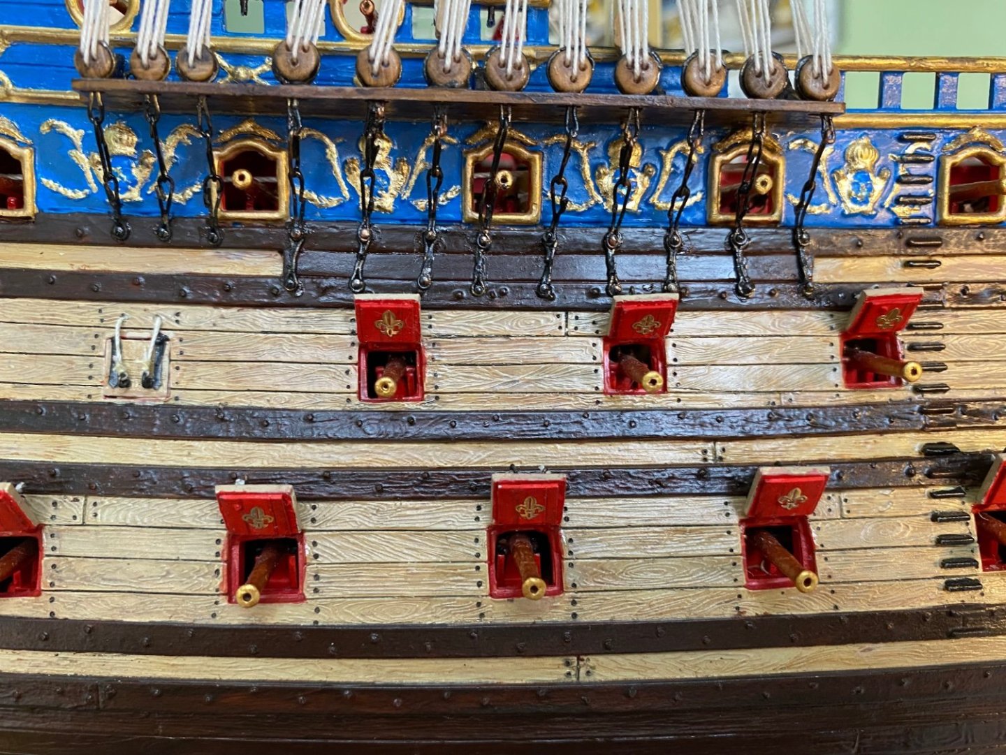
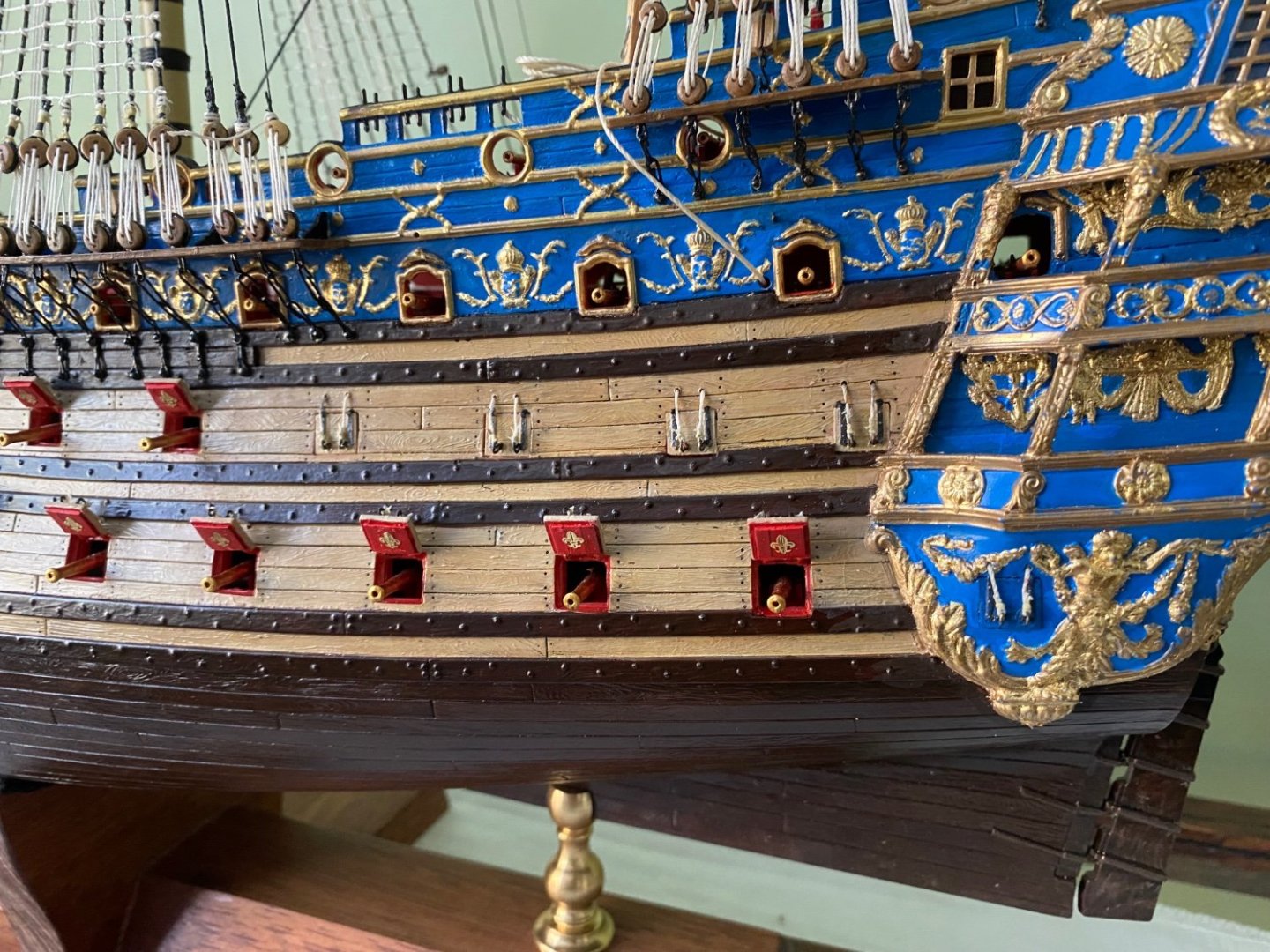
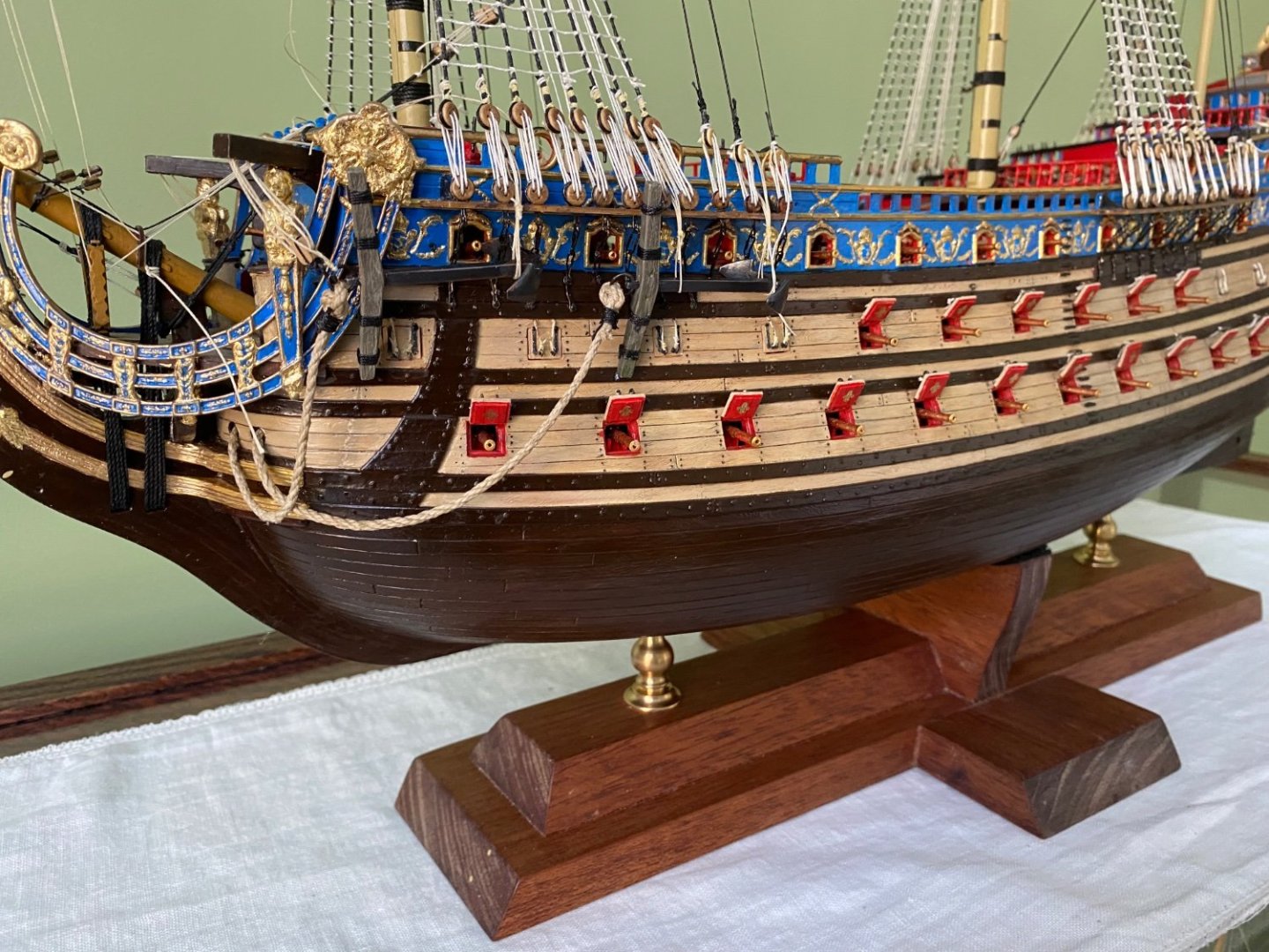
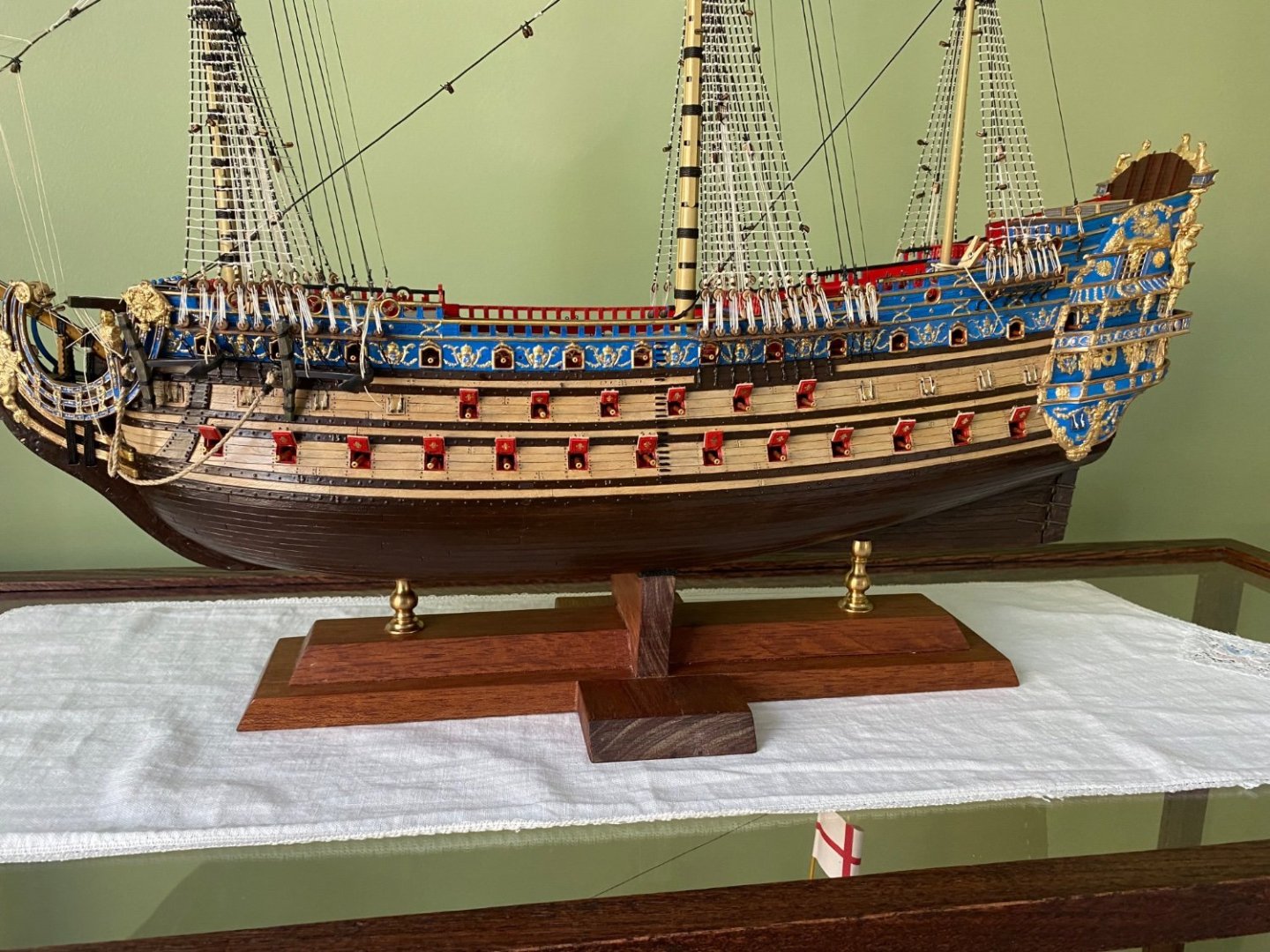
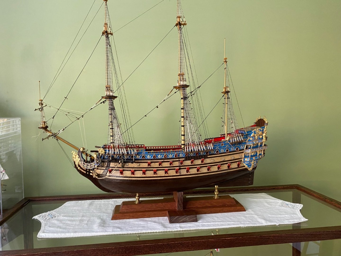
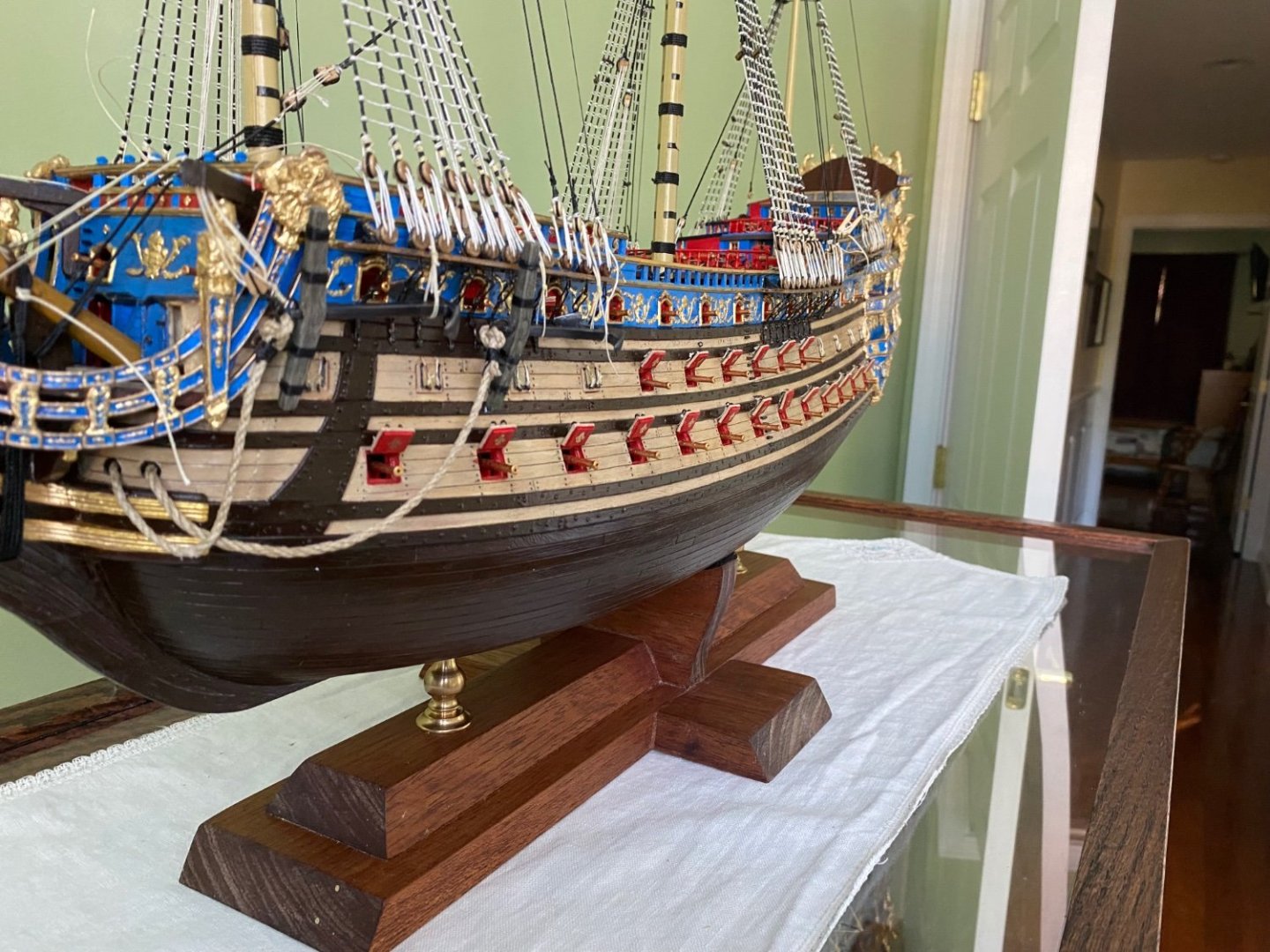
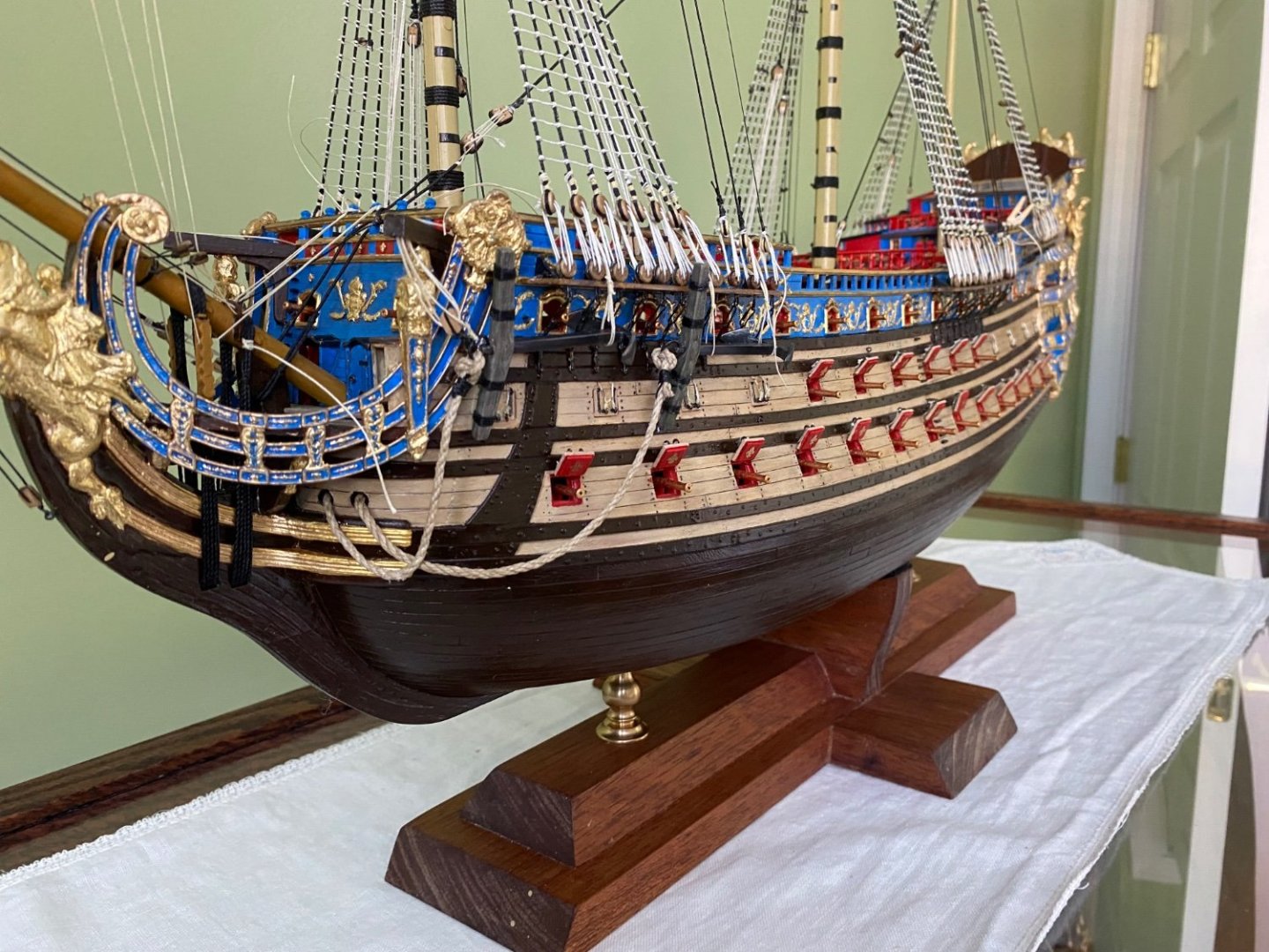
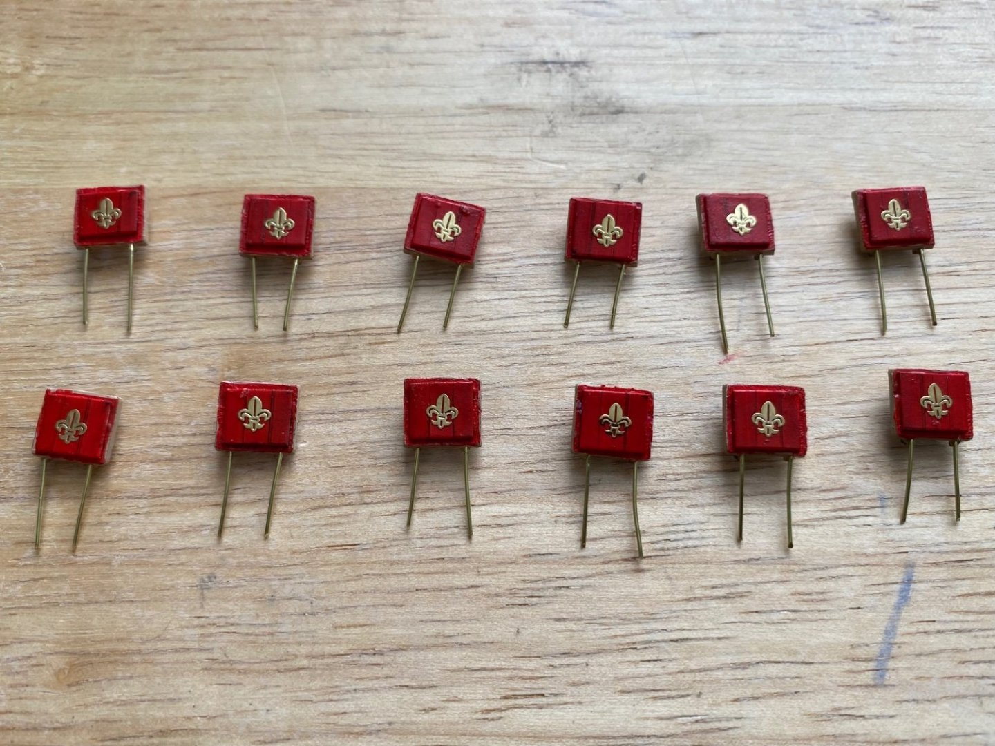
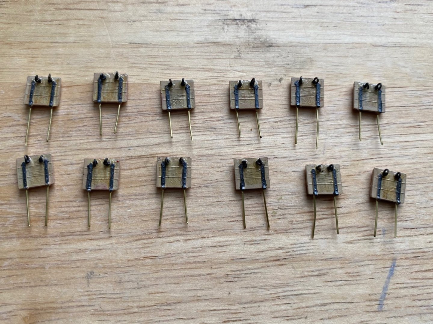
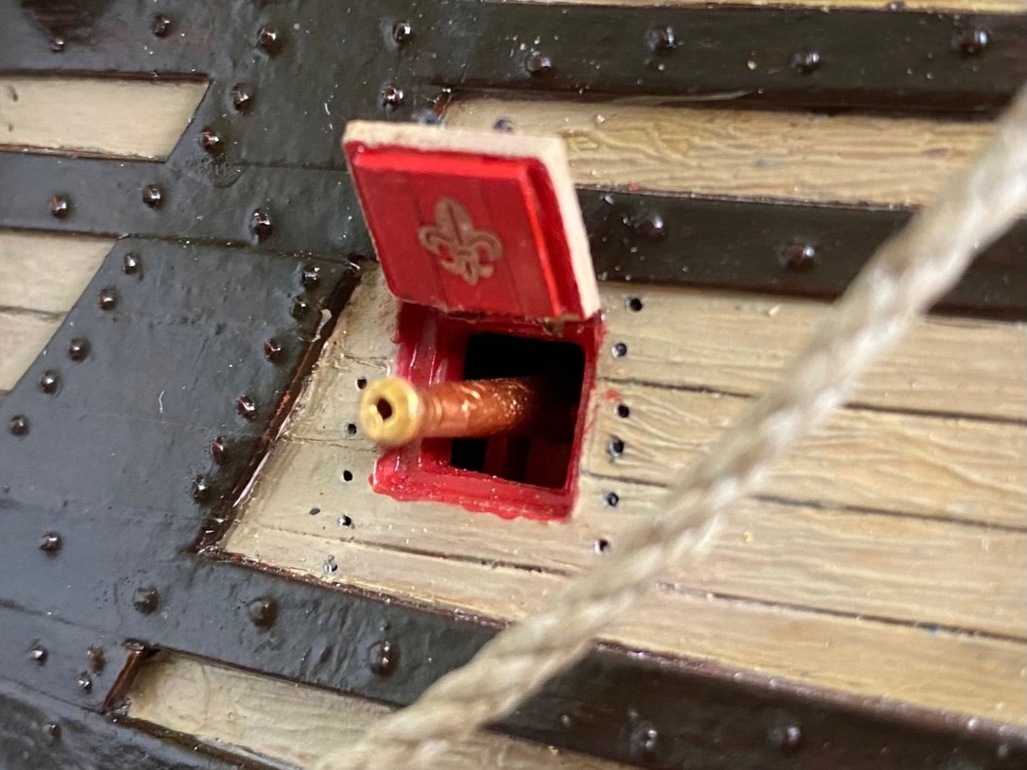
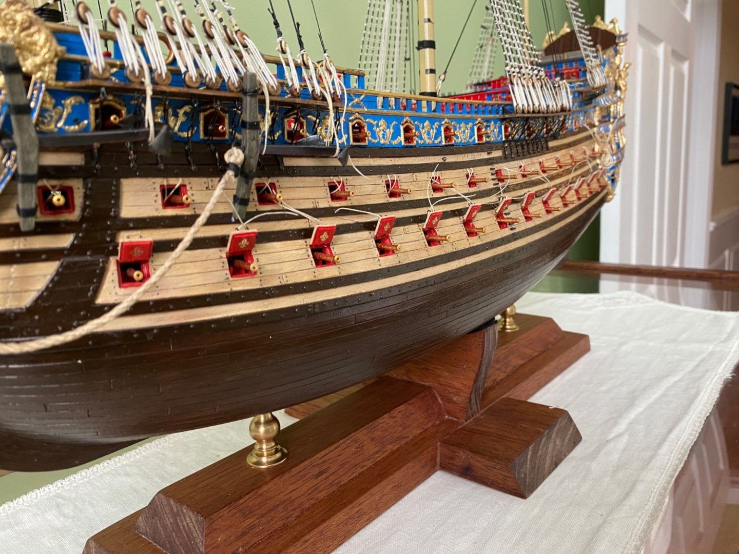
Finished the cannon hatch covers all around. Repeated the 4-6-4 layout on the starboard side as I did on the port side. Opened the four hatches on the stern. Making all the little metal eyebolts for all the hatches, and lashing the pair of lanyards for each cover (opened and closed), was right up there with tying ratlines. 😊. Also added the fleur-de-leis to each of the open hatch covers. Doing a little kit inventory. I know I still have the lanterns to add later. I would surly break them off if I added them now. From what I can tell I think I am primarily going to be working on the yards, sails, and rigging from now on.


- 1,508 replies
-
- 7
-
-

-
- Le Soleil Royal
- Heller
- (and 1 more)
-
Beautiful Ian. You guys doing your own 3D printing of parts are taking model building to a neighborhood I have never been too, nor does my GPS have any idea where it is! 😀
- 536 replies
-
- 4
-

-
-
- Quadrireme
- radio
- (and 1 more)
-
I am very happy with my Heller Victory I finished last year. I do have an OcCre kit in my stash that I will start after I complete my SR. It will be my first attempt at a wooden ship that I am looking forward to. I will watch for anyone that builds this ship though.
-
I started to go 5, 5, 4 but the ship profile looked more balanced and symmetrical with a 4, 6, 4 layout. On a side note, have any of you seen the newly released today limited addition OcCre wooden HMS Victory? If not, check it out. Absolutely incredible but way outside my budget.
- 1,508 replies
-
- 1
-
-
- Le Soleil Royal
- Heller
- (and 1 more)
-
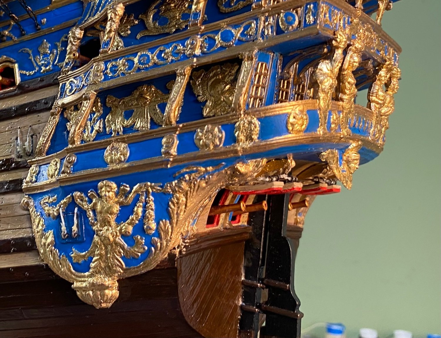
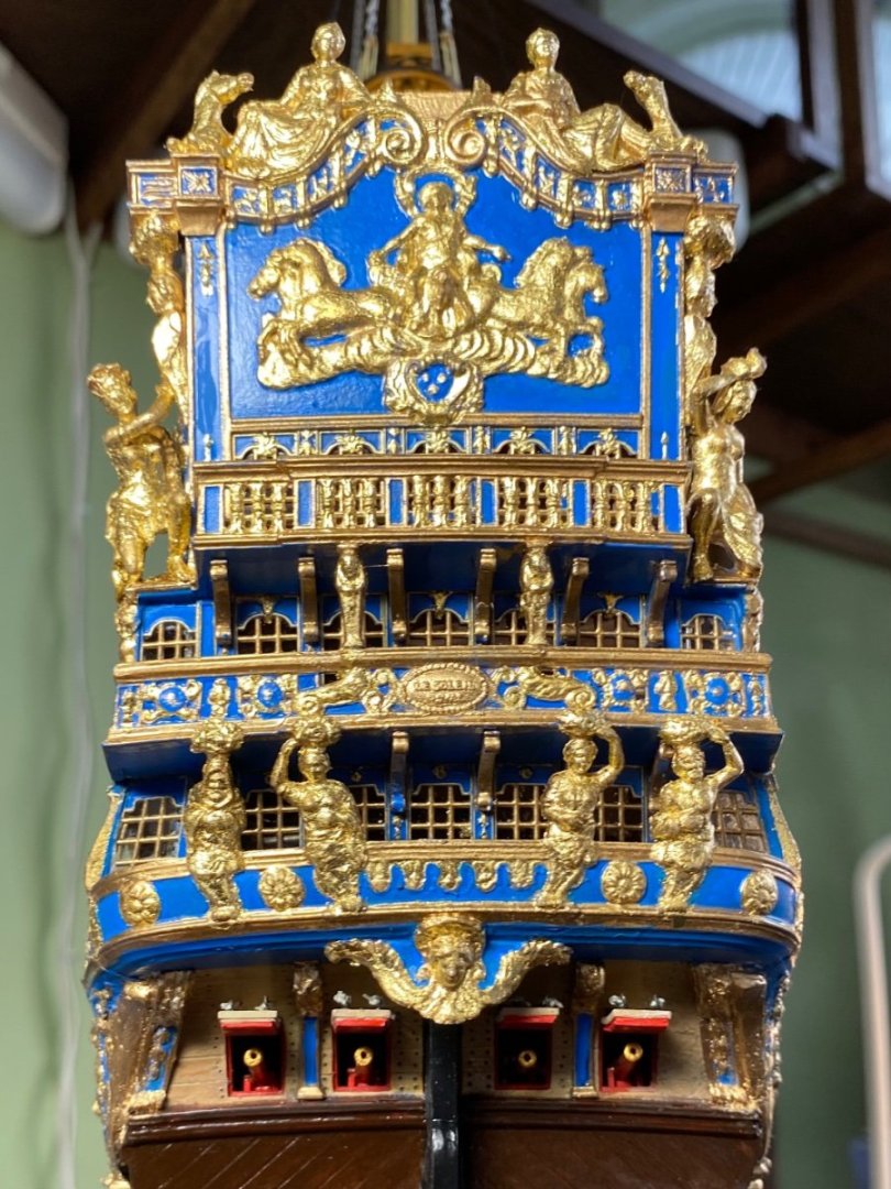
Picture this - The 1st Lieutenant orders the guns to be exercised by division. The second LT, who is in charge of the second deck battery, orders the first division, in this case it could be the first four guns on the port side, to prime, load, and fire. He will compare their best time with the other divisions for a bit of competition. Henry I liked your scenario. In my display the 2LT ordered the 2nd Division to prime, load, and fire. 1st and 3rd Divisions are at rest with hatches closed. 1st Division has already fired, pulled cannons back, and closed the hatches. 3rd Division is waiting anxiously for their orders. The exercise includes the opening and closing of the hatches in the drill for best time. Last time 3rd Division won by more than 85 seconds! This lead to a couple reassignments of members of the 1st and 2nd Divisions to permanent deck scrubbing until further notice. Needless to say 1st Division was much better this time and we are waiting to see how 2nd Division performs. The 2nd Division does deploy 2 more cannons than the 1st and 3D, but they are the most highly trained. 😊 I also closed the hatch on the side gallery.
- 1,508 replies
-
- 7
-
-
- Le Soleil Royal
- Heller
- (and 1 more)
-
My friends I just happened to scroll back to the beginning of my build log and I see that this past weekend was one year since starting my Soleil Royal. What a fantastic adventure it has been with all of your help. Can’t imagine how many hours I have invested so far, with many more to go. On a previous build I thought I should keep a log of my hours just to eventually see how many. But then I thought who cares? The pleasure is in the adventure!
- 1,508 replies
-
- 4
-
-
- Le Soleil Royal
- Heller
- (and 1 more)
-
Henry I like your narrative. I think I remember that narrative in Master and Commander.
- 1,508 replies
-
- 2
-
-
- Le Soleil Royal
- Heller
- (and 1 more)
-
All open on the battle side? Not some open and some closed? Only on side (port) of my ship will be fully visible in its display case. Was thinking of having some closed on the visible side but I am guessing that would not be authentic?
-
As I am working on the cannon hatch covers I am noticing that I like the way the covers look closed as well as open with cannon forward. I am curious if there would be an authentic way that in actuality would have had some covers open and some closed? I am interested in the same side of the ship. I always have my preconceived display side. As you have seen I already have the cover’s installed on the port side lower deck in the open position. If I wanted to display some of the hatches on the next deck up (but not all) closed, what might have been an actual situation? A few on each end closed and those in the middle open, or the opposite of that? An alternating hatch cover open/closed display? What do you guys think. Of course any I decide to close now will require the removal of the cannon barrel.
-
Ian the RC model boat group sounds fun. Not only do you need to build a beautiful ship, you need to make it float and move. As Marc has made very clear in his modification of the Soleli Royal kit. There is no way it would not tip over based on the shape of the hull. Luckily I don’t have to worry about that.
- 536 replies
-
- 2
-
-
- Quadrireme
- radio
- (and 1 more)
-
Ian this is absolutely fascinating! Your mechanical and electrical engineering skill is so over my head but I still enjoy reading through it, especially the videos. Great job my friend.
- 536 replies
-
- 3
-

-
-
- Quadrireme
- radio
- (and 1 more)
-
Wow Ian would love to see photos of your Galley. It really sounds pretty cool!
-
Thanks Ian. I will always say your help and guidance on the Victory has been my foundation for this build. Am I correct that you have the Heller Soleli Royal in your stash for a future build? Will be anxious to see what you do with it.
-
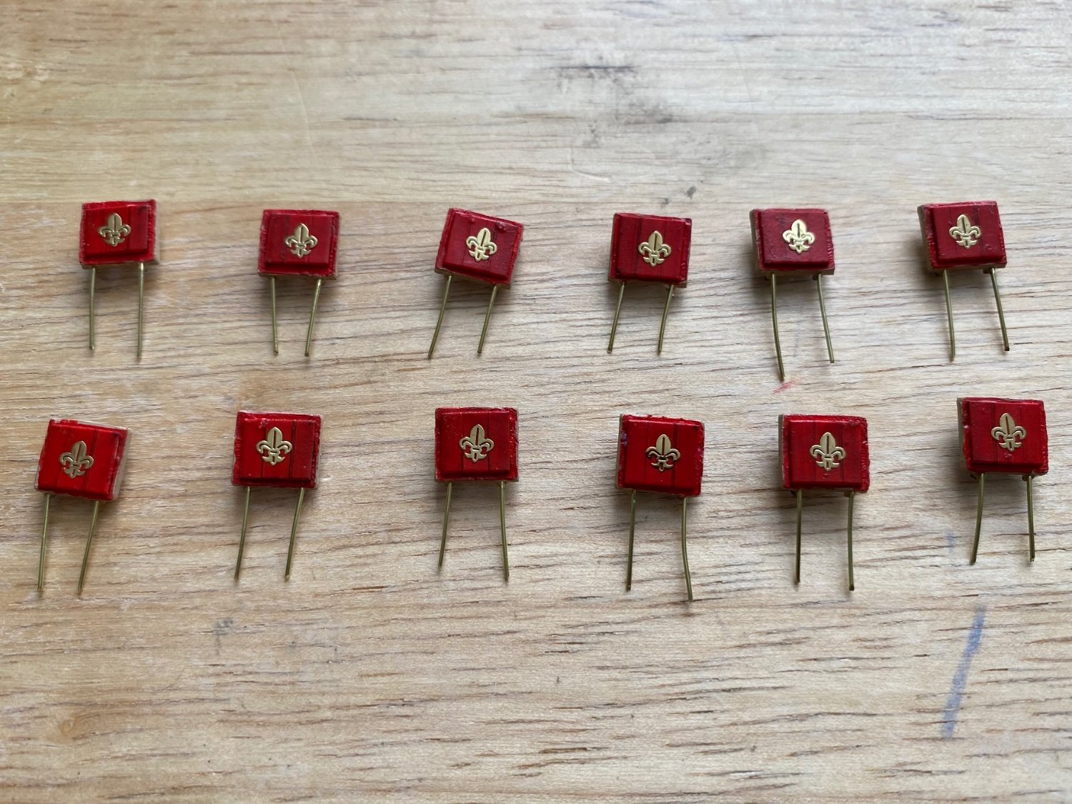
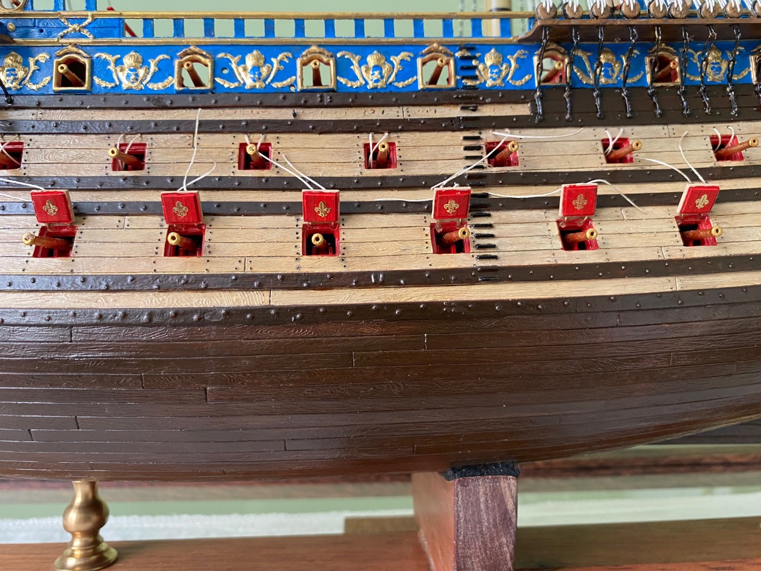
Thanks Henry. I believe what I have rigged so far matches what you have. More lines to be run later! It is crazy flipping back and forth between 3-4 pages! 😊 In the meantime I have decided to go with cannon hatch covers next. The method I am using to install them allows them to be flexible so I should not have a problem breaking them off. Did an extensive modification of the kit hatch covers. I added a layer of Evergreen to the inside to better reflect the hull thickness. I cut them lined down the face of the Evergreen to resemble wood planks. Painted the interior side red and added a gold fluer-de-leis face up when hatch is open. On the face side I painted the hinges and added two eyebolts to except the hatch lanyards. To attach to the hull I drilled the top and added two copper wires with a touch of CA. To attach I will drill matching holes in the inside edge of the hatch and insert the wires again using CA. The wire will permit the covers to be positioned just as an actual hinge would. Bottom deck on port side completed except for lashing the lanyards. Still need a little paint touch up around a few hatches.


- 1,508 replies
-
- 4
-
-
-
- Le Soleil Royal
- Heller
- (and 1 more)
-
Henry after much study I believe I have the rigging correct. The old 1970’s version of the rope routes and belay points was better to follow than the new one that has a few discrepancies, I think. I am at a decision point as to where to go from here? I imagine I will need to lean the model over a bit, both starboard and port, when I add the cannon hatch covers. I somewhat expect with the yards attached, especially the fore and main, tipping the model could be awkward. So I can’t decide if I should go ahead and put on the hatch covers before I move on to the yards?

- 1,508 replies
-
- 2
-
-
- Le Soleil Royal
- Heller
- (and 1 more)
-
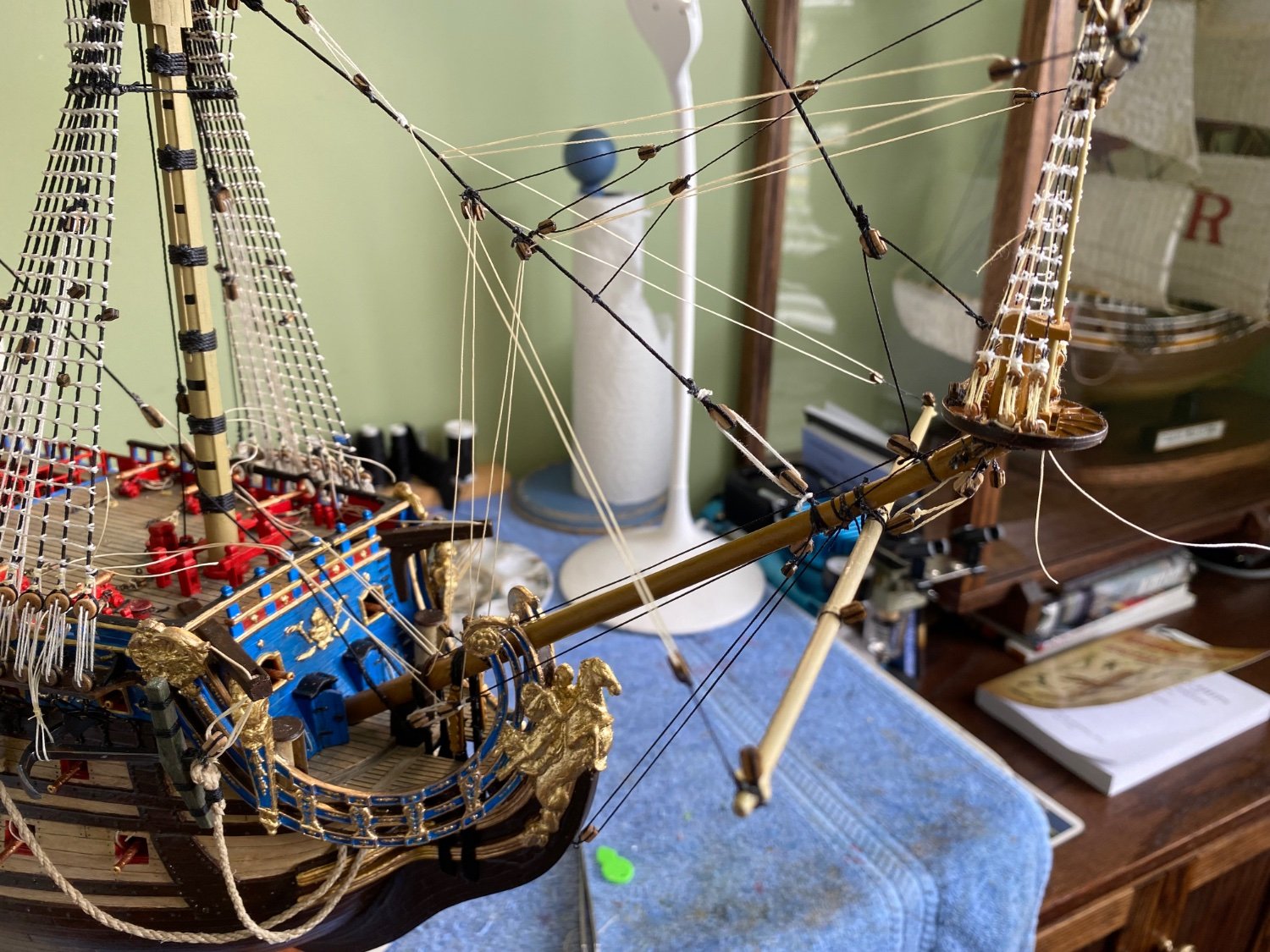
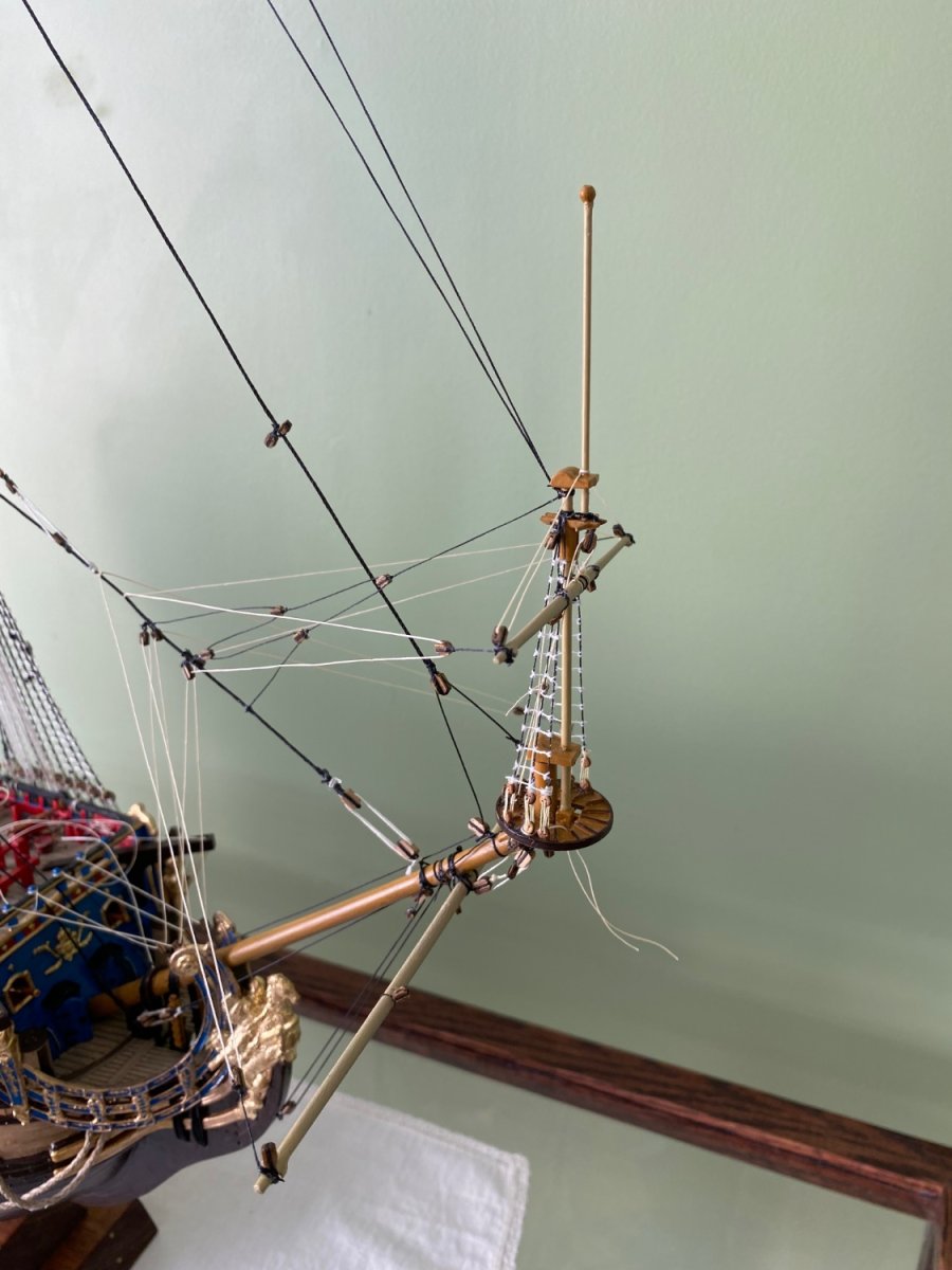
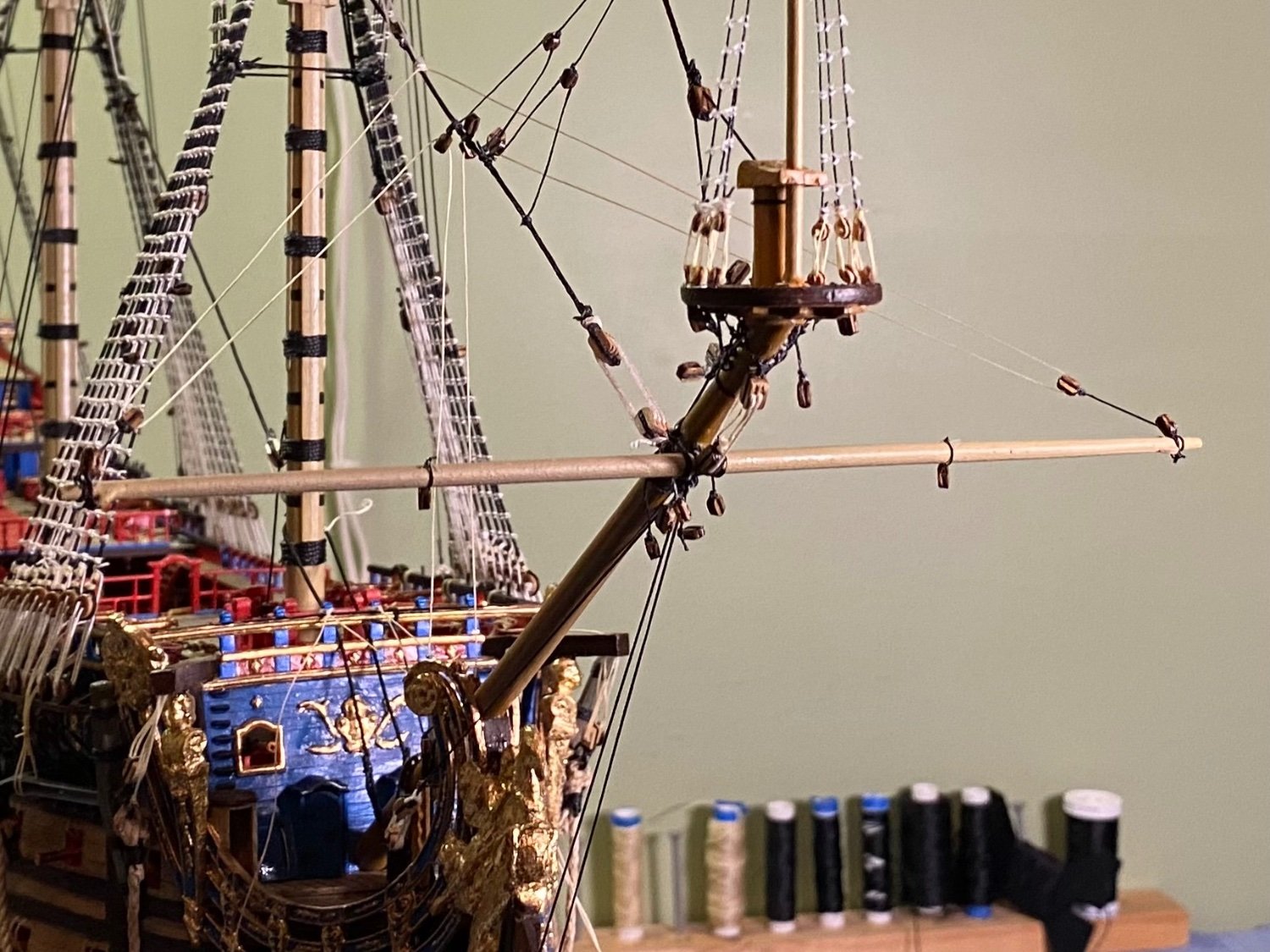
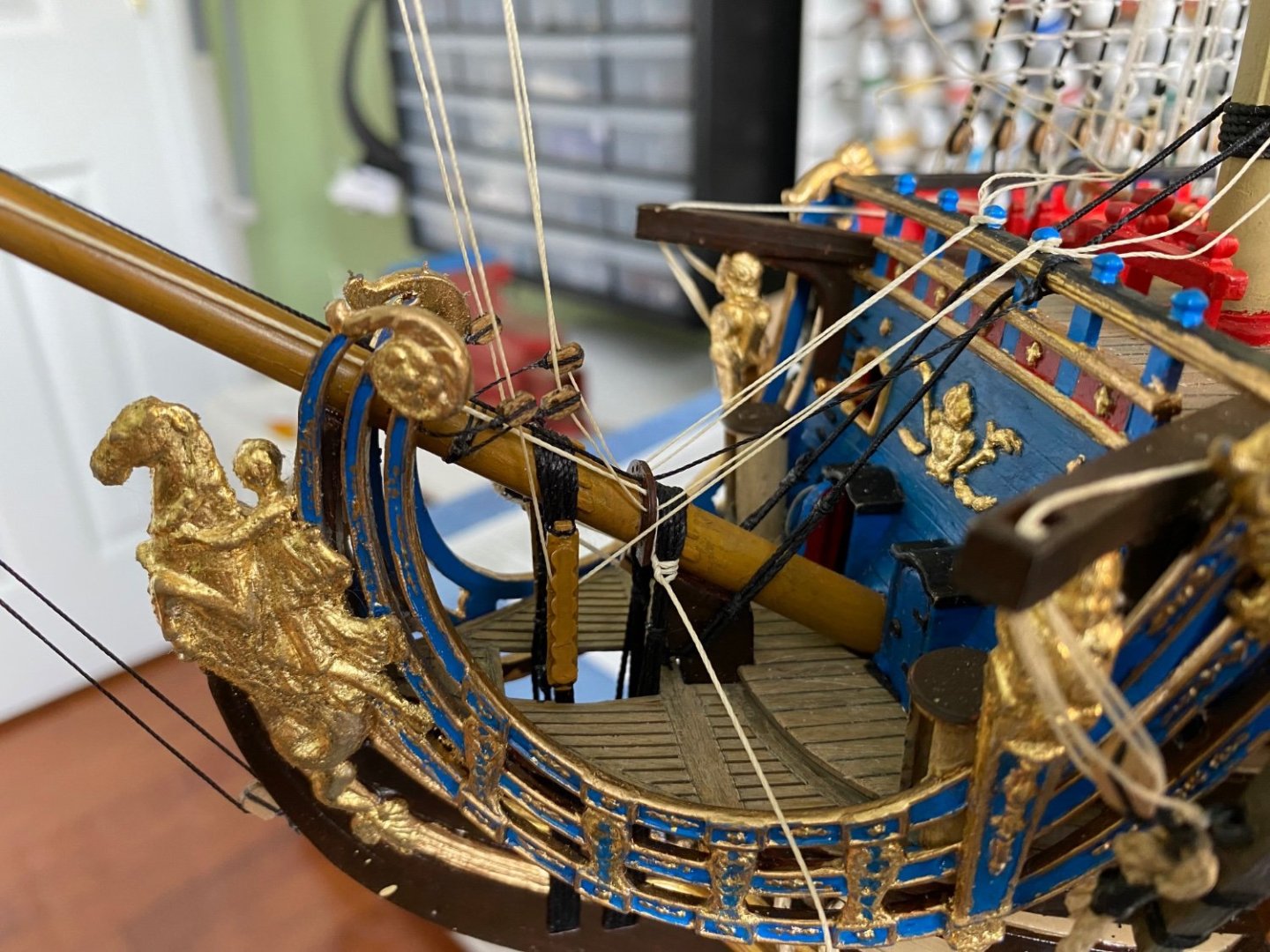
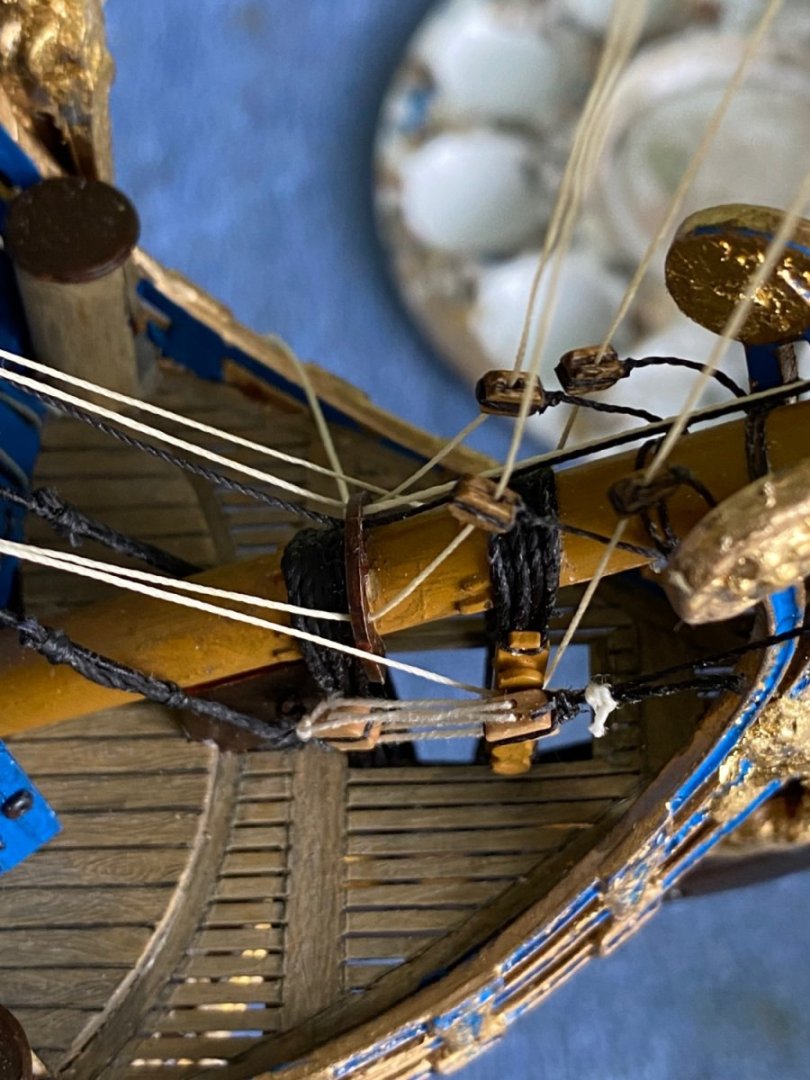
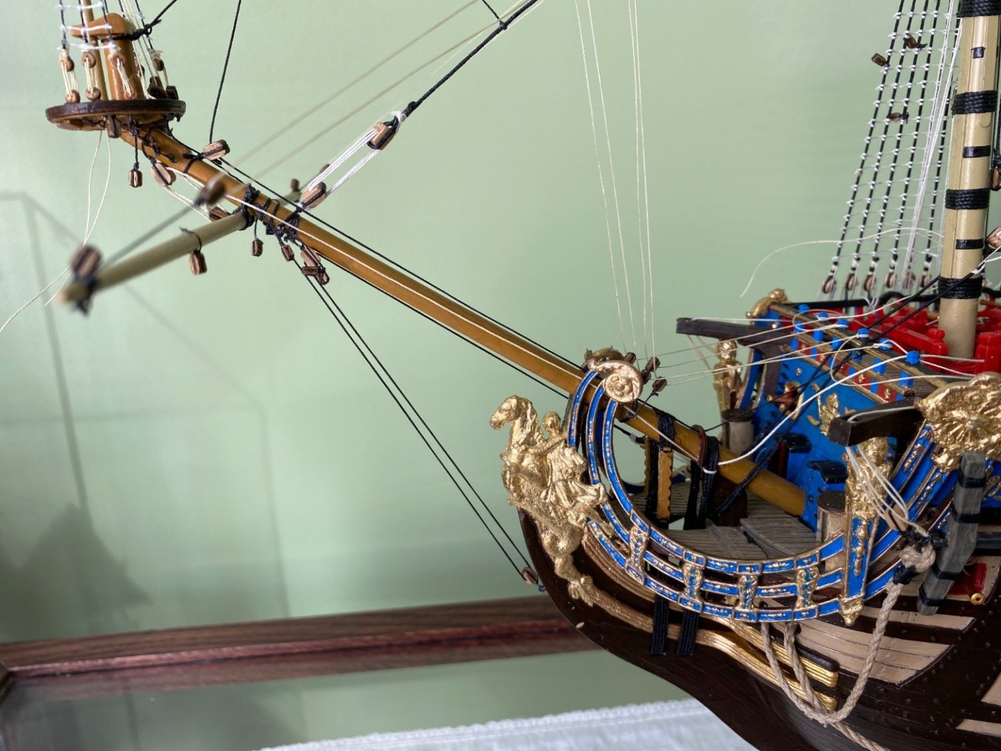
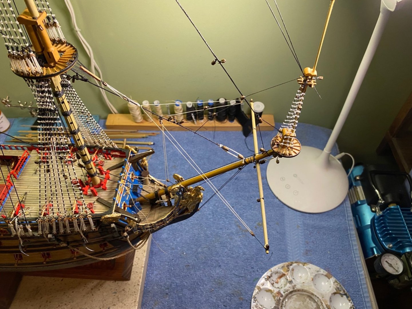
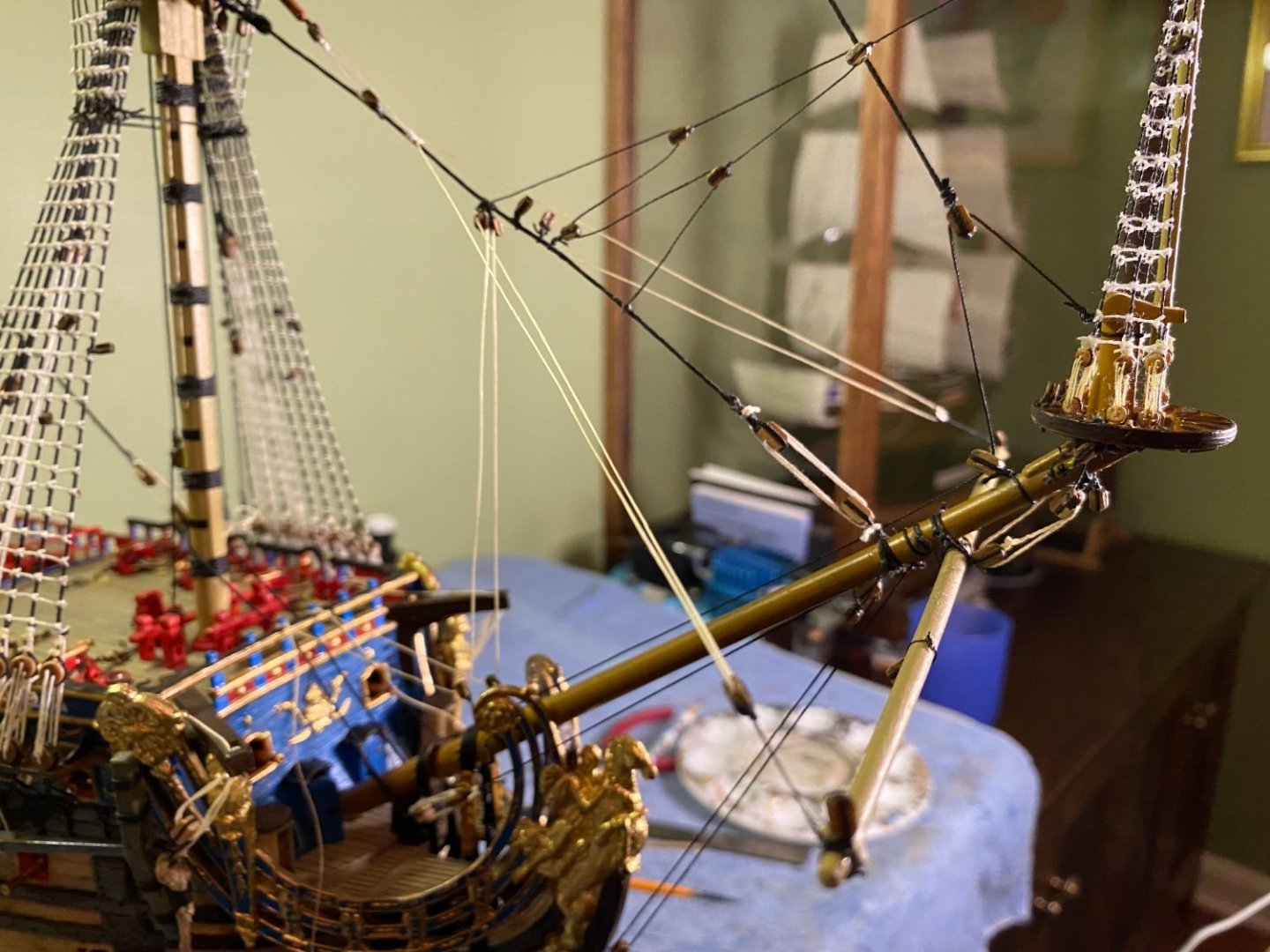
Henry in my first photo you see the line that goes through the block attached to the center of the sprit yard then through the block under the platform and down alongside the bowsprit. The rigging path ends with it being tied to the gammoning. I have two Heller instruction versions. An older version has it going through a hole in the saddle and then to the gammoning. The version that came with the kit has a different line going through that particular hole and indicates the line in question does not pass through the saddle but instead goes directly to the gammoning. Can you make a definitive conclusion for how that line completes its run? Also for the lines that go up to the beakhead rail I see some belay to the rail while others belay to the knightheads lined up along the rail?
-
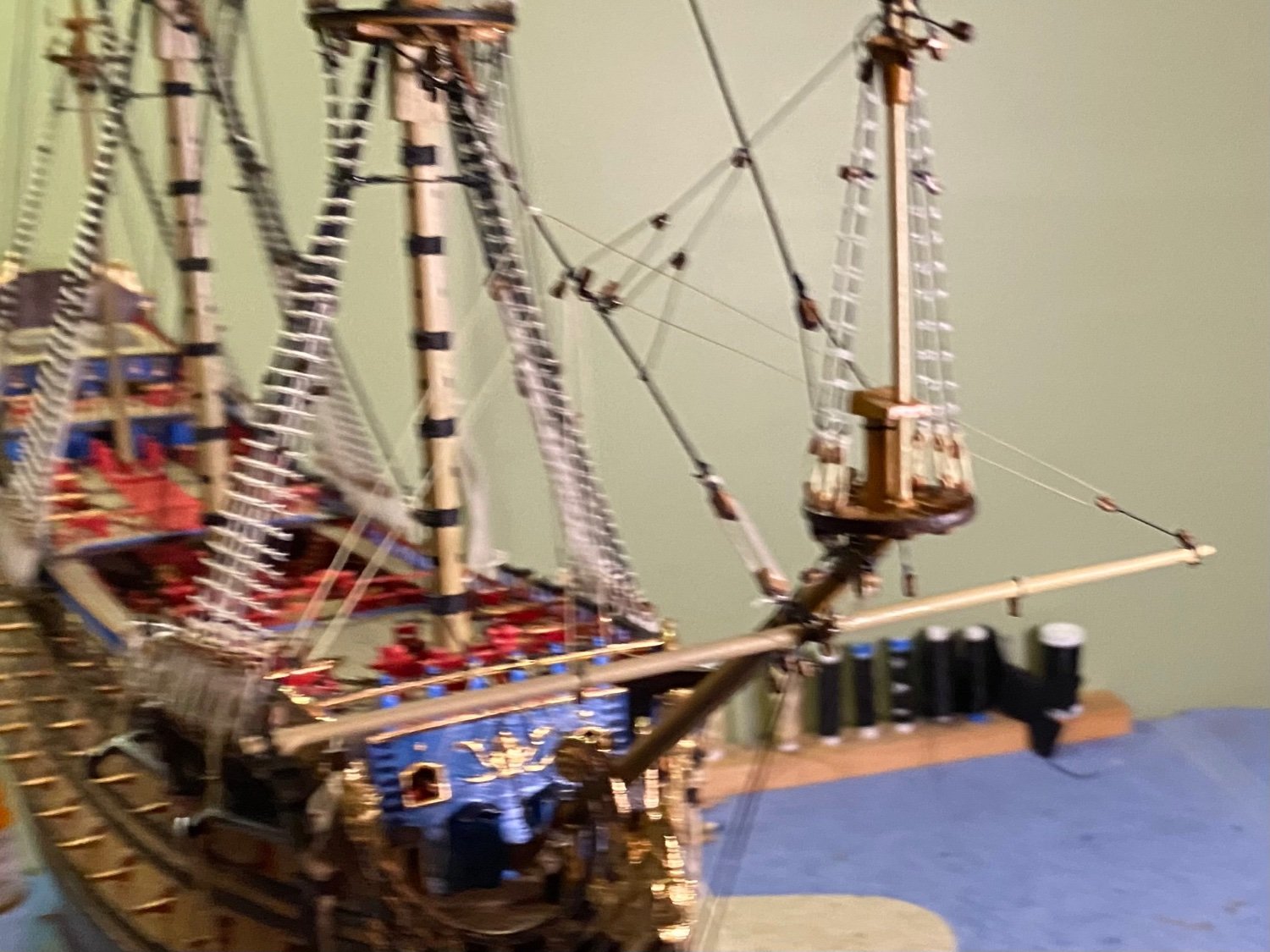
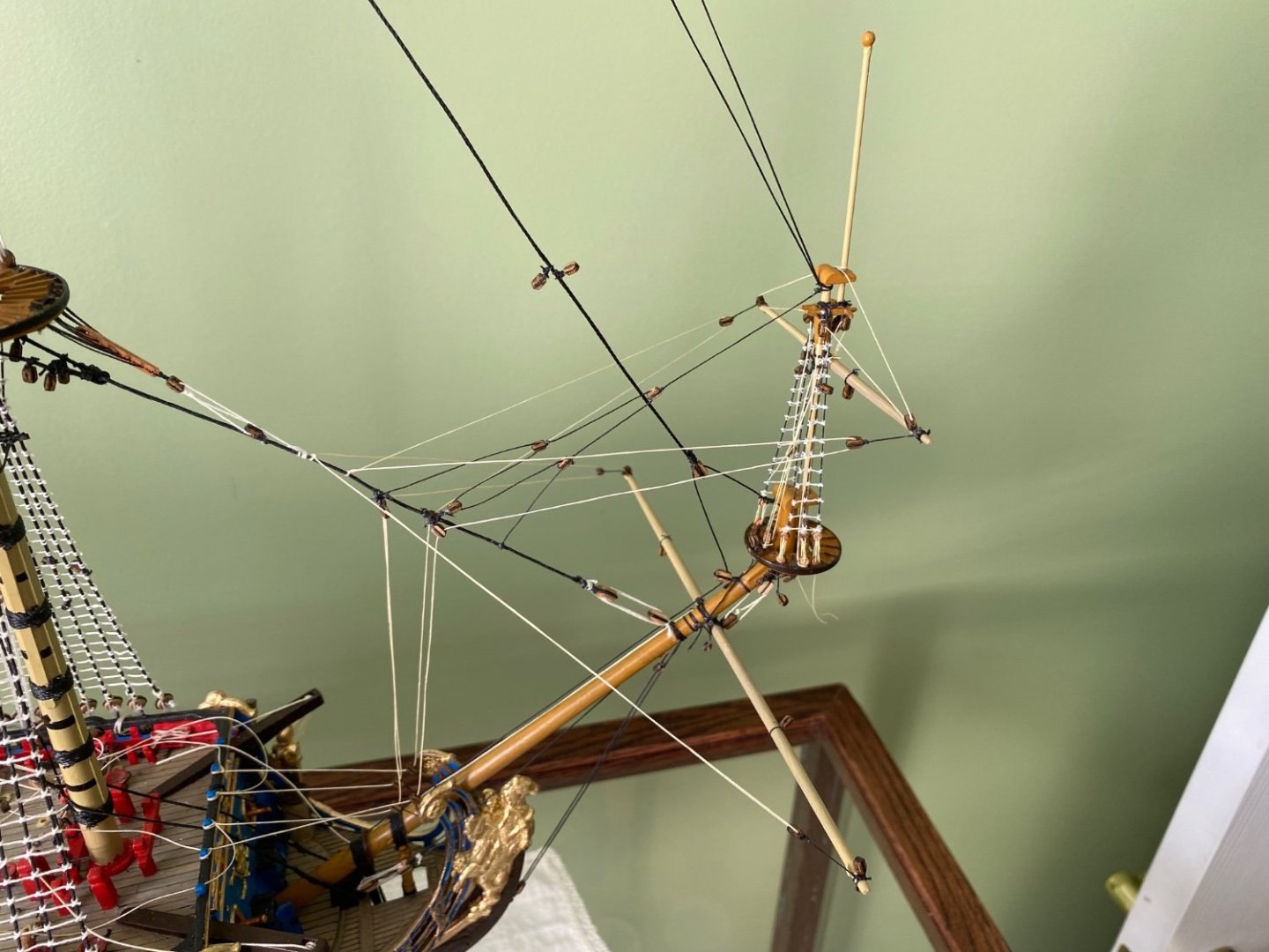
Top sprit yard installed and rigged. There surprisingly is a lot of rigging to that little yard! Still studying to determine the exact belay points for the halyards for it and the spritsail yard. One instruction I have shows the lines going through the holes in the bowsprit halyard guide then up to the rail. Another instruction has them going directly to the rail or tie off to the gammoning.

- 1,508 replies
-
- 2
-
-
-
- Le Soleil Royal
- Heller
- (and 1 more)
-
Thanks Henry. I really appreciate it.
-
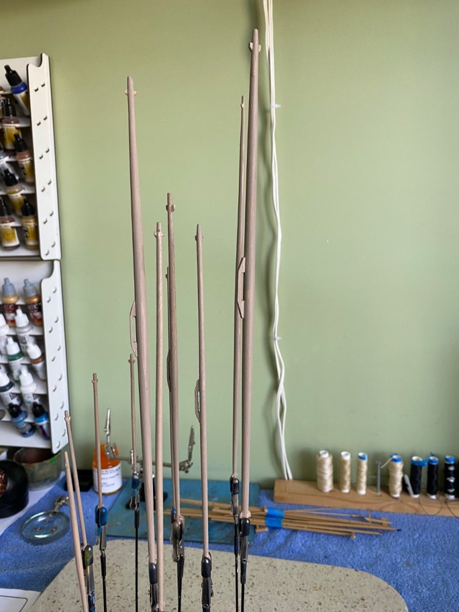
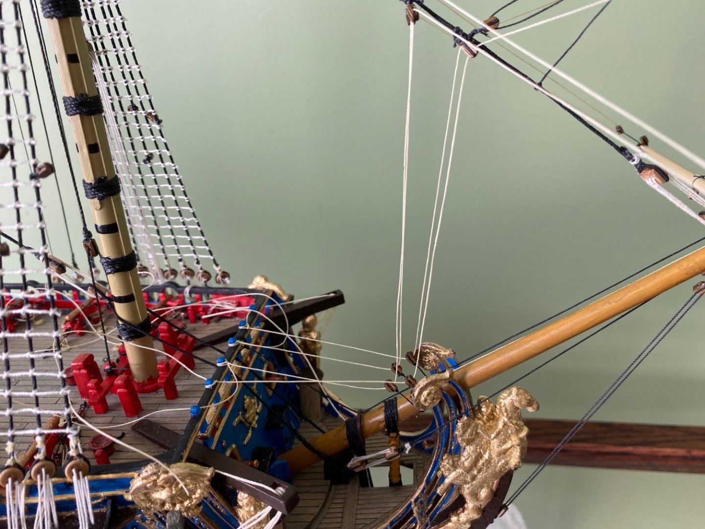
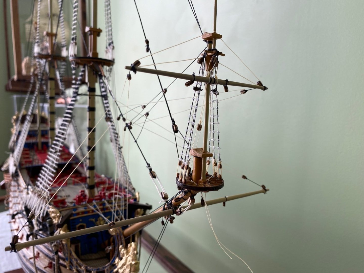
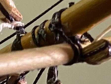
Attached the spritsail (do you call the yard the spritsail or the spritsail yard?). Made the spritsail sling just as described in Anderson’s book. Also added a few of the rigging lines. Since I reinforced the bowsprit with a wood dial, and turned new yards out of dials, all my spars are solid wood, either entirely or within the plastic. This enables me to use the old trick of drilling a small hole on both pieces at the contact point and inserting a pin with a touch of CA. This holds the yard in place while the sling, parral, and/or other initial rigging is added. The copper 22ga wire is flexible so I can manipulate the yard to the desired position without needing 6 hands!😊 You can also make out the pair of little triangle cleats I added to all the yard arms after I turned them. I used wood to make the center cleat you see in a couple posts back. For the yardarm cleats I cut tiny triangles of the appropriate width Evergreen and set them in from the end with CA glue before painting.


- 1,508 replies
-
- 4
-
-
-
- Le Soleil Royal
- Heller
- (and 1 more)
-
All of my newly made wooden yards complete with cleats in the center were appropriate and on the ends of all of them. Primed and ready for the paint booth!

- 1,508 replies
-
- 3
-
-
-
- Le Soleil Royal
- Heller
- (and 1 more)