HOLIDAY DONATION DRIVE - SUPPORT MSW - DO YOUR PART TO KEEP THIS GREAT FORUM GOING! (Only 36 donations so far out of 49,000 members - C'mon guys!)
×

Rik Thistle
-
Posts
864 -
Joined
-
Last visited
Content Type
Profiles
Forums
Gallery
Events
Everything posted by Rik Thistle
-
 Derek, She's looking great, which isn't surprising considering all the fine and detailed work you have put in to her. It's almost mind boggling in places ;-) Chris certainly gives us our money's worth with these kits. Richard
 -
Swann Morton chisel blades.
Rik Thistle replied to harlequin's topic in Modeling tools and Workshop Equipment
Shipman, Thanks for the heads-up. ...from .... https://www.scalpelsandblades.co.uk/range_23_swann-morton-supatool-blades-and-handles.php You and Bob are right that the standard SM blades can be a bit fragile. They also can be a bit dangerous if left lying around, when fitting a blade (I use pliers) , and removing the old blade (I use the SM 'box'). Richard Edit: the Supatool may also be called the 'industrial handle' in the UK? ... https://www.amazon.co.uk/Swann-Morton-Retractable-Industrial-Handle-Fitting/dp/B007Q3ZT6E/ref=pd_sbs_6?pd_rd_w=mtyOc&pf_rd_p=fbd048ad-ab90-4647-94dd-974b91bedef1&pf_rd_r=C6WXGKWB9JXCEHNCDXWG&pd_rd_r=1ada9340-d2e7-4901-a964-a6440851b422&pd_rd_wg=XPoxO&pd_rd_i=B007Q3ZT6E&psc=1 -
Glenn, So much fine detail and a perfect colour scheme is a feast for the eyes. You'll be happy but sad that's she's finished 🙂 Great stuff. Richard
-
Excellent. Precise, to the point video. Do you need to choose a depth of field that throws the background out of focus, just in case there is a minor wrinkle ? Or does PhotoShop Clone stamp take care of that? Thanks, Richard
-
Glenn, GlennBarlow|Photography Yes blatant self promotion Wonderful pictures. Each one deserves a good, long look. But, what's going on with the sliding stone on the dry lake bed?...the wind, or a feral Roomba Robot vacuum 😉 Richard
-
Derek, Excellent! You've shown me what is possible 😉 Yes, there are loads of good photographers on here and it's great that they are prepared to share their experience and give tips. Richard
-
a feature in Photoshop I am using frequently is the geometry correction. Yes, once I discovered there was a PS method for correcting barrelling and pincushion there was no going back. But it probably led to a bit of laziness when clicking the shutter button. Richard
-
It would appear from the posts in this thread and viewing a lot of the builds on the website that we cover almost the complete gamut of photography skills from enthusiastic part timers to highly skilled and experienced togs. One thing I would note, and it is something I am guilty of, is that one needs to become really familiar with one's photography equipment. These days I use my 'big' camera kit (a Panasonic 4/3rds) infrequently and usually take the route of least resistance .... my Android phone (less buttons and settings to think about). But Summer is arriving so I will make a serious effort to refresh my big camera photography skills. As someone once asked "how do I get to Carnegie Hall? - practice, practice, practice" Richard
-
BTW, if you are interested, here are my own modest attempts: https://www.imago-orbis.org Wefalk, I perused your website shortly after I joined MSW and apart from being very impressed by the excellent locations you visited, the photography also caught my eye. I particularly enjoyed your Speaker's Corner pictures. I visited there a number of times whilst I was living in London from 1972 to early 80s...perhaps we may have been in the same small crowd that used to gather round the Speakers. Some were downright crazy but some were making excellent points. Anyway, back onto the topic 😉 Richard
-
There is a strong local attachment to Unicorn in Dundee, Yes, there has been an awful lot of money spent on the Dundee waterfront iover the past few decades Dundee has really upped it's game. It would be difficult to imagine the local power brokers letting HMS Unicorn leave Dundee. But mabye there could be some kind of horse trading done with Hartlepool? Richard
- 13 replies
-
- 6
-

-

-
- HMS Unicorn
- preservation
- (and 2 more)
-
Just looked over this Ken Rockwell's Web-site. The guy seems to have his nose pretty much up in the air and he prides himself being an 'artist', I feel. His pictures are colourful, but not that much more. Yeah, that kinda sums Ken up. A lot of his comments are tongue in cheek though. He does like 'vivid' pictures. I still think he does take pictures that capture the emotions of the places he visits eg Yellowstone. Richard
-
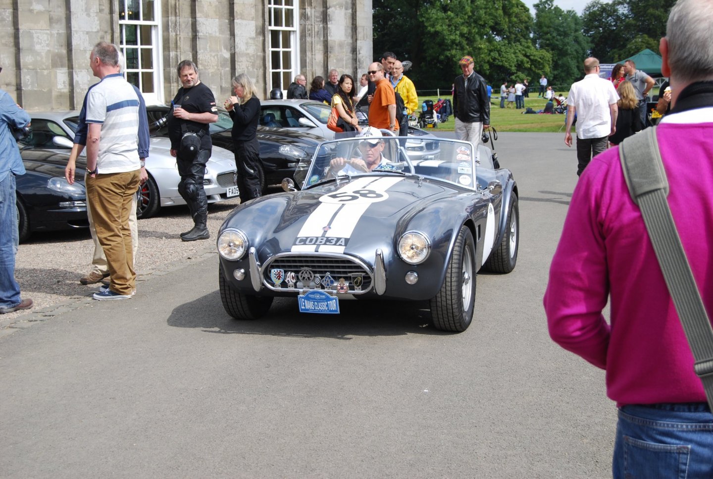
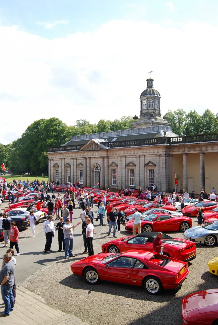
B.E., Those pictures are excellent. Thank you. And glassy waters 😉 So the two models in the glass case .... both are HMS Unicorn?...one at a smaller scale and the other how she will look when one day she is returned to her former glory? She'll make a magnificent model. It seems sufficient budget had been found .... https://www.eveningtelegraph.co.uk/fp/hms-unicorn-secures-funding-to-restore-model-of-port/ ...and the restoration work will by Will Murray of the The Scottish Conservation Studio, Hopetoun House, South Queensferry .. https://www.scottishconservationstudio.co.uk/contact/ Richard PS: Hopetoun House is a superb building and grounds...well worth a visit. They hosted The Italian Car and Bike Show a number of years back ...the pics below tells you how successful that day was ... OK, the above doesn't have much Italian content in it but no one was complaining, but the cars below certainly were Italians... The above was a small part of the collection. It's a shame they never held it there again. Richard
- 13 replies
-
- 5
-
-
- HMS Unicorn
- preservation
- (and 2 more)
-
ISO/ASA 50 film had a much finer grain than ISO 200 Yes, indeed it had. I shot mostly B&W back then (the home darkroom set up was much simpler than colour). B&W also had a certain appeal to me...I think it was because the shapes and composition were the eye catching points, rather than the colours. But these days I rarely convert a colour image to B&W.... thought - I wonder if my Panasonic GX80 can switch the viewfinder to B&W? Richard
-
This looks like quite a challenge.. HMS Unicorn goes under the microscope for preservation project ..... https://www.bbc.co.uk/news/uk-scotland-tayside-central-56818539 "HMS Unicorn is the oldest ship in Scotland and one of the six oldest ships in the world. The 46-gun frigate was built during peacetime and launched in 1824, spending its early life in reserve, anchored on the River Medway. HMS Unicorn was moved to Dundee in 1873 to become a training ship for the Royal Navy Reserves. It was almost scrapped in the early 1960s when Earl Grey Dock was filled in as part of preparatory work for the Tay Road Bridge. After its move to Victoria Dock, the vessel was handed over to the Unicorn Preservation Society in 1968, and opened to the public in 1975." Richard
- 13 replies
-
- 5
-
-
- HMS Unicorn
- preservation
- (and 2 more)
-
Glenn, Yes, it was a general statement 'brighter is better', all other things being equal. The more light one has to begin with the more flexibilty you have with the camera settings. I remember reading Ken Rockwell's site quite a number of years ago when he was talking about film photography ( https://www.kenrockwell.com/tech/modern-exposure.htm ) and he mentioned he generally used ISO 50. I couldn't understand that - here in Scotland I was struggling to use ISO 200 to get sufficient flexiblity between aperture and shutter speed. Then I realised that where Ken lived (San Diego) the outdoor light was much, much brighter. Richard
-
"... lightweight microphone tripods ..." Ah, you've reminded me I have a full length mic stand and at least a couple of desk mic stands, somewhere. The snag with my LEDs is that they don't have a 1/4" Whitworth thread ...but tie-wraps, at a pinch, could hold the head onto a stand. But, to be honest, I think what I've got at the moment is worth persevering with, for a while. The only slight drawback is that they are not height adjustable...but that is what a thick book is for 😉 Richard
-
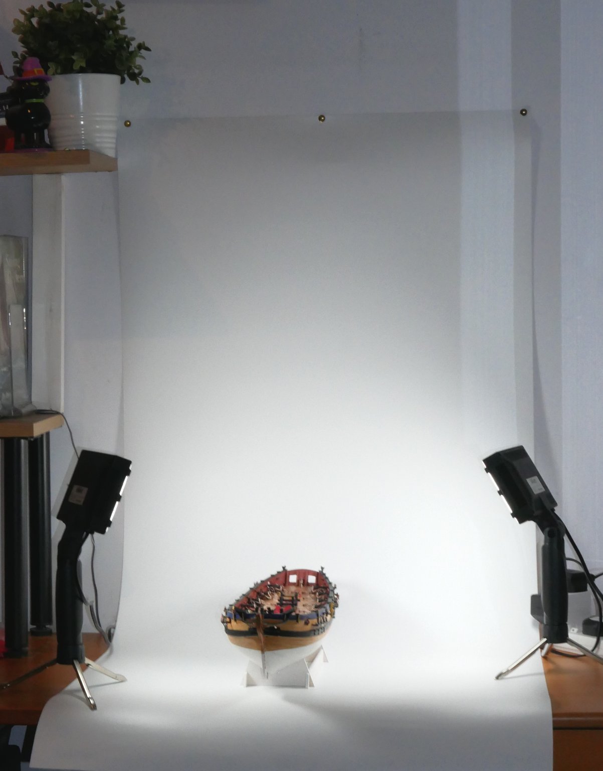
That looks very convincing. Yes, PS is a great tool - I'm very rusty on it and am currently using paint.net for my needs. A quick snap of my 'new' set- up ... Total outlay appx £46. Lights £30 + backdrop £16. I'll need restraints on the tripod feet or they'll be meeting the floor soon. There's some stray light off mirrors but that can be sorted. It's a bit blurry but gives an impression of the light brightness available from the (non-adjustable) 2x LED lamps. They'll never get close to sync'd flash but for current needs good enough. I didn't bother adjusting the camera's settings so will be able to post brighter images in future. Richard

-
Yes, I did try searching for a large enough grey (18% ?) background but couldn't find anything reasonable. And I didn't what to spend too much time in s/w removing the grey. I tend to restrict my camera metering zone to a small box (not spot or wide) so that kinda removes the influence of the white background. But for my basic needs, at the moment, I'll go with what I've got for now. Richard Edit: Just found large grey backdrops on Amazon....I'm sure they weren't there a few weeks ago 😉
-
I do have a light box but it's not quite large enough to accommodate a model ship and it's tall masts. I'm currently rearranging my study to place my white backdrop against the wall and bench top, with my LED lights, one either side of the ship. iPhones are really very good at taking pics. I believe one can use focus stacking to simulate a deeper depth of field - not sure if the iPhone has that s/w built in. I use Android. But for 95% of picture taking mobile phones are now good enough for generally most things. And, as you say, are very convenient and good for tight spots. James H (IIRC) was kind enough to explain in one of his builds how he did his photography for Vanguard Models Instruction books. It was essentailly a white back drop and a couple of lights...at least that how I remember it as being. I'll need to check. Richard
-
Ras, A little bit of filler, good sanding down and a coat of paint and she'll look like a million dollars. She's progressing very nicely. Richard
-
Gary, The Luxli Fiddle (at around $200, less diffuser) is 'almost' justifiable for me... maybe one day. Ken Rockwell has favourably reviewed Luxli's products. After I went into semi-retirement I worked part time as a videographer (in the days of DV tape) and we used, IIRC, halogen lights on the cameras. The halogens threw the light further than LED lights which was an advantage when quite a few feet away from the subject(s) in a dark'ish room. But for product photography, LEDs are now likely the better choice due to a more dispersed coverage, longer battery life, and they run cooler, I guess? Richard
-
Simple guide to product photos
Rik Thistle replied to Rik Thistle's topic in Photographing your work. How to do this.
Allan, Yes, he has quite a lot of relevant, useful info on his YT channel. By 'north light' do you mean a bluer light as opposed to a warmer light? Richard -
Hi all, Here's a 9 min video intro to making product pics using everyday items. .... DIY Product Photos - Easy, Cheap and Good-looking He's got a simple, clear way of explaining things. The light he's using seems quite bright and fairly close to natural daylight. But a camera's Auto White Balance should make a reasonable attempt at trying to emulate daylight if a different temperature of light source is used. I don't recall him mentioning camera settings etc I've just noticed he has some other videos that might be usefull eg.... - The "Make Almost Any Product Look Good" Lighting Setup https://www.youtube.com/watch?v=7XuXILkrn5A - "Make Almost Any Product Look Good" - Part 2 https://www.youtube.com/watch?v=SjZl09ntVxI Regards, Richard -
-
start considering rigging prep now Good idea. Rather than tackling all the rigging in one large push, it might be useful to nibble away at it whilst doing other bits, gradually building up the nibble sizes as I go. Richard
-
Matt, Yes, both apply. Pays your money takes your choice ;-). Bright lighting at around 5600K (appx daylight) is ideal. I've been reading Ken Rockwell's website for quite a few years and he has a great take on photography, sometimes tongue in cheek. Richard