HOLIDAY DONATION DRIVE - SUPPORT MSW - DO YOUR PART TO KEEP THIS GREAT FORUM GOING! (Only 36 donations so far out of 49,000 members - C'mon guys!)
×

Rik Thistle
-
Posts
864 -
Joined
-
Last visited
Content Type
Profiles
Forums
Gallery
Events
Everything posted by Rik Thistle
-
 Mark, I can only be inspired. The skills and abilities of these folks are to be admired....eg If only non-technical folks understood what is needed to produce those works of art the world might be a better place. That's not to say other disciplines lack merit, but I do feel that there has been a trend over the last 30 - 40 yrs to push younger folks towards the less hands-on careers. Anyway, I'll have a good read through that link over the weekend, thanks. Richard
 -
Hi all, A short post to start the day with, focusing on three of the main castings. Below, L>R, - the Standard, which is the structural link between the reciprocating stuff (the piston) and the rotating stuff (the crankshaft), - the Sole Plate, which fixes the relative positions of the Standard and the Crankshaft - and the Box Bed, which is attached to the ground, and adds stability and strength to the structures above it. It may have other functions (vibration dampening?) that I'm not yet aware of - I'm thinking real world scenario. From the above.... - the Standard has been cleaned up by eye on the sanding belt to add approximate squareness and also to remove some of the hard casting surface layer. - The Sole Plate has had it's top and bottom surfaces machined to size on the lathe using the 4 jaw chuck. The hard casting surface is nicely highlighted (the shiny perimeters) on the Sole Plate...in places it is up to 1 mm deep. I had started off by using HSS cutting tools but quickly switched to carbide tipped tooling to cope with the hard layer. The Plate also features cast-in dimples to indicate where fixing holes should be drilled. The positional accuracy of those dimples should generally be taken with a pinch of salt! - The Box Bed had it's top and bottom surfaces (and mounting lugs) milled flat using the tiny MF70. I was keen to experiment with different finishing methods (lathe, mill, filing etc) to get experience and see what worked best. The milling was quite a long process taking tiny cuts at a time...probably the hardest part being winding the table back and forth. I also drilled and tapped 7BA holes in the top surface along with 'I forget' sized holes on the mountimg lugs. Below, the Standard (unmachined but sanded) being visually checked on the Sole Plate and Box Bed. The circular hole running through the Standard is important in that it needs to be aligned correcly with the components it interfaces with...more in later posts. Below, the Standard being held in the lathe courtesy of an Aluminium tube running down it's (roughly cleaned up) bore. The tube was from a piece of old, dismantled Ikea furniture (lamp stand?) which was stored in the 'that might come in handy one day' bin....well it did 😉 Luckily the tube had a threaded end and matching countersunk screw which forced the Standard against the jaw surface. IIRC, I also added a peg to the tube to stop the Standard rotating under cutting loads. Above, the Standard's two feet cleaned up nicely. As I was making the 10V engine I was only occassionally taking pictures mostly for my own reference rather than for a Build Log. But with 20:20 hindsight I may have taken just enough pics to form some kind of haphazard log. So apologies now, if I tend to jump back and forth between items as I post. This was meant to be a very short first post for today, followed by a longer post (ie more pics) later today. I'll see how I feel 😉 All the best, Richard
.thumb.jpg.135ee194c3cc2f8c84c915974f5d95b6.jpg)
.thumb.jpg.c28ea3859c9243f4f2fd7a9b8ea28900.jpg)
.thumb.jpg.e621fdd4716d052df9c27791a52e8b6b.jpg)
-
Bob, Thanks for the info; I'll have a good read Yes, there seems to be a thriving market for quality steam models. Keith Appleton not only makes and sells his own superb models but (I think) acts as an agent for other modellers ... 'SOME SUPERB MODEL STEAM PLANTS - NOW SOLD' - https://www.youtube.com/watch?v=Najs8o412Oo&t=348s Even Bonhams are in on the act .... https://www.bonhams.com/auctions/25163/lot/310/ I doubt if any of the modellers are in it to make money, but rather for the sheer pleasure of building and operating the equipment, and of course, learning. In addition to Keith Appleton, a couple of my favourtie YT sources are Andrew Whale and Tinker John Both explain clearly what they are doing, the mistakes they make and the equipment they use. I'll mention others as I go along. So far, I've spent (too) many hours watching YT builders and reading websites. I suspect my small but growing 'model ship building library' will soon have some new companions from the 'steam model' world eg Where the Rails Meet the Sea which I saw mentioned on a different thread in this forum the other day. I'll try to post some more pics of my build later today. Richard
-
Funny you should say that Bob .... https://www.mainsteam.co.uk/mainsteammodels-gallery 😉 I've spent quite a bit of time reading through Keith (Appleton) website, and there are many glorious examples of what can be done with steam engines. I find it a fascinating subject. Richard
-
Hello all, In June 2021 I bought Stuart Models 10V steam engine castings set.... https://www.stuartmodels.com/item/39/stuart-10v-unmachined Plan being to get me more outdoors ie in the shed with the door open enjoying the great summer and nature flying and buzzing all around. The build took about 12 weeks using a Sieg SC2 lathe, Proxxon MF70 Micro Mill, bench grinder/sander, bench drill, hand tools .... and a calculator. It's many decades since I did 'metal work' professionally but after a few weeks a lot of it 'came back to me'. So did making mistakes and then figuring out to remedy them ;-). This was a totally fun project. I have since bought the Stuart 'Reversing Gear' kit of castings, what with this being a 'ship' website and steam engines on boats/ships needing a reverse gear. And that will be next summer's project. Also, there is the tiny seed of an idea in my head that one day I'll add a boiler, build a waterproof model boat, fit servos etc ....add the lot together and go RC sailing...but that's in the future, maybe. Anyway the Stuart box arrived in late June.... A simple but sturdy cardboard box, with the metal contents held in place with a strong, transparent sticky covering....they weren't going anywhere! The 'paperwork' is a single large sheet with the parts' detail drawings on one side, a Parts List, Exploded View and very basic instructions on the other side. It could be argued that the drawings did kinda dimension all aspects of the parts that needed machining, but it was prudent to study those drawings closely and also consult other sources. An inventory check showed everything was present..... One of the 'other information sources' is shown above - the booklet by Andrew Smith. It has gone through a number of revisions and gone as far as converting BA thread sizes, dimensions etc into Metric... hmm. Below a first look at four of the main castings...clockwise from top left, Sole Plate, Cylinder, Standard and Flywheel. Castings sometimes have a very hard outer surface (due to cooling) that makes machining difficult. So I proceeded to skim as much as that hard surface off as allowable, using files and a sanding belt. Note: I say 'allowable' since some of the casting surfaces were right up against the borderline regarding what the finished size would be. Above, a slightly blurry pic of the Box Bed having it's top and bottom surfaces machined flat and parallel, and square to the rest of the item. (Edit: It looks like I was actually drilling out the mounting lugs rather than milling flat the top and bottom surfaces....that milling had been done earlier) The mill above really is 'micro', with the largest diameter cutter being 3 mm. However going slowly and taking no more than 0.25mm (10 thou) cuts max, a reasonable result is achievable. I had spent some time fettling the mill on arrival eg adjusting the gibs, adding ball thrust bearings in the Z axis and a Z axis digital readout. So it all worked fine...for a while (...blunt tooling tended to 'grab' quite easily). Below, centre drilling the two main fixing holes. I later bought stubb drills which were the proper tool for that job and have a slightly longer reach (I think the stubb drills might be shown in the pic above). OK, that's it for today. I'll post more over the next few days. Spoiler alert. I have already finished the engine and successfully 'run' it using an electric drill attached to the crankshaft. Which is putting the cart before the horse, since the power is meant to come from the steam in the cylinder, which in turn drives the flywheel (attached to the crankshaft). But building a boiler, or even sourcing compressed air is for a later day. Catch you soon , Richard PS: I really do plan to now get back working on HMS Flirt.
.thumb.jpg.be6106787b169776aed9d5c02324ac24.jpg)
.thumb.jpg.046c30439d159830c9ce4b1c5c856ded.jpg)
.thumb.jpg.493fb03eaffdba0a80ece26fbba5bd5c.jpg)
.thumb.jpg.54c6598fd93edb6380dc1e4cf6d62fc4.jpg)
.thumb.jpg.daae1b852644a1f68efab25873f7a916.jpg)
.thumb.jpg.9b0ad265aaf4826c83fc5b87671b6d23.jpg)
- 55 replies
-
- 12
-

-
HO trains and layouts by popeye the sailor
Rik Thistle replied to popeye the sailor's topic in Non-ship/categorised builds
Popeye, A great read, and also the 'plastic model kit' history link to John Loughman. As a kid I lost count of the number of aircraft windscreens I messed up with the kit glue. Not the glue's fault...just my ham fistedness 😉 Richard -
GranpaPhil and Glenn, Thanks for the comments. Dallas sits about 4' above and to the right of my shoulder looking down on me...as does Lady Eleanor. Both are keeping an eye on me I feel 😉 I've been side-tracked with a model steam engine build during the great summer we've had in Scotland and therefore have spent many days (and evenings) in my shed/workshop. The model steam engine is a generic version of the kind used in early steamers so there is a maritime connection. As usual it's the 'oh, that looks a quick and easy part to make' parts that turn out the opposite. But I hope to get back on Flirt soon'ish since the nights here are starting to draw in. Richard
- 41 replies
-
- 2
-
-
- artesania latina
- dallas
- (and 1 more)
-
Lots of very good creative detail there Ras. She's going to be a feast for the eyes, as well as the hungry mouths waiting back on the mainland. Richard
-
I felt the tension in this video .... 'Ship in a bottle foremast placement' - I don't know anything about 'ship's in bottles' but this seems to be quite a challenging hobby. I wish the builder had a lot more videos on 'how to' on his YT channel. But there will be others. Anyway, off to do a bit of learning on the hobby. It's above my pay grade but quite fascinating. Richard
- 1 reply
-
- 2
-

-
-
Erik, I think that because Tom is such a likeable character and knowledgable presenter it all helps make his content that bit special. As for having to go to sea in a Fifie (or similar) in bad weather to survive, well it sends a shiver down my spine. But needs must. Richard
-
B.E., "...great value to the modeller. It informs both scale and use of the many fittings, as well as being of general interest." It certainly does. I now have a much better appreciation of the full sized Reaper and the models based on it. Also, I'm slowly working my way through the other 6 episodes ....'Episode 2 - Pts 1 & 2 Phoenix' explains square riggers in a very practical fashion ... I'm learning so much. Richard
-
Hand, Reef and Steer by Tom Cunliffe Being relatively new to model boat and ship building I'm only now realising that Tom Cunliffe has made such a great contribution to sailing. Here he is, in 2010, with the first episode of 6 on the 'Boats that built Britain' series, The Reaper .... Richard
-
I just had an image flash through my brain of the four Vanguard fishing vessels, all in approximately the same paint scheme., lined up on my sideboard....it was a very pleasing image ...oh, oh. 😉 Richard
-
Glenn, Those pics are hitting the spot! Well done. And these days with so many pixels to play with, cropping can be a reliable assistant. Richard
-
Glenn, I am going to experiment with using the Canon's .... Like most things worth doing it takes a fair bit of effort to become competent, so you are doing the right thing in exploring the camera funtions and getting hands-on usage. And there's lots of websites and YT posters and folks on here that help provide all the know how we'd ever need. I'm far from competent but know enough to at least know when I'm getting a poor result 😉 And from that I learn. When cameras were analogue the 'menu system' was pretty much common across all brands of camera makers ie once you learned what the the knobs and buttons did on one brand you could use another brand with minimal learning curve. But now we have touch screens and software menus, sometime with useful functions hidden way down in a sub-menu....grrr, and that's all compounded in difficulty by each manufacturer using their own software menu systems....it's one of the tricks they use to lock you in to the brand. From what I understand modern Canon cameras have the best interfaces, followed maybe by Nikon and with Sony at the bottom of the pile. But all menus are learn'able ...it just takes time. Richard
-
Glenn (UK), Yes, all as Glenn says .... and you've noted using the matt side of the backdrop will help prevent reflections. And I think you've already got the diffusers fitted to the LEDs to spread out the light a bit more gently. Also have one or two white reflector boards (roughly 10" / 250mm square - anything white will do eg Polystyrene packing) at hand to bounce the light from the LEDs onto the parts of the ship that are too dark or need extra highlighting. Here's a clip from one of my favourite YouTubers getting involved in lifting a heavy light to help illuminate the set on a Commercial shoot.... https://www.youtube.com/watch?v=Hwzlk-0SQDU Note the numerous LED panels and reflectors, all there to totally control the lighting...natural sunlight is great but it works to it's own schedule 😉 Richard
-
Laggard, I've tried most methods of plank bending including the 'soldering iron' version you mention. So far, it's my go-to solution.... it's compact, can do bends in two ot three planes with a bit of practice and luck. I sprinkle water on the wood and the proforma (to improve heat transfer) before putting the hot iron to the wood. A drawback is that it doesn't have an auto-time off feature, or warning light that it is On. So one needs to keep skin etc clear of the hot tip till it is cool, and to remember to switch it off when not in use. Richard
-
Derek, What a build...so much to take in and to such a sky-high standard! Richard
- 725 replies
-
- 3
-

-
-
- vanguard models
- speedy
- (and 1 more)
-
Glenn, Your finished HM Cutter Alert looks great - very well done 🙂 And thanks for all the detailed pics and explanations which will come in very useful for me. Richard
- 160 replies
-
- 1
-
-
- Alert
- vanguard models
- (and 1 more)
-
I'd love to ride in Scotland someday. I'd love to ride California one day 😉 . I've always bought Trek or Marin bikes so Marin County is also on the list, but I think my travelling days are over. One of my favourite Scottish road + scenery circuits was to set off from Aberfoyle with a group of friends and do a circuit around Loch Katrine. It's Rob Roy country so very picturesque with quiet, small roads, tiny villages and hamlets with mountains on one side and Loch Katrine (with the Sir Walter Scott steamship) on the other side. Having been to quite a few countries on business and holiday I think I'd probably pick Lake Louise are a choice cycling destination. Skiied there but never cycled. Anyway, take it easy with the cycling for now and just enjoy the fresh air. Richard
-
Man, the pavement is unforgiving! My left knee, hip pointer, wrist, elbow and shoulder plus road rash have all healed up but my left rib cage is still very sore. My head actually bounced on the pavement. Ouch! I hope the rib cage eases up soon. It's probably bruised cartilage between the ribs, not that I'm an MD. I find it shocking that a lot of cyclists don't wear safety helmets ... a typical excuse is... "it messes up my hair". I have a (gory) response to that which makes them reconsider their position. My mountain biking days are behind me now, but I still try to get out on the country roads as often as the Scottish weather will allow. Richard
-
a) "Material posted on MSW shall not be shared with other forums in any manner. This includes but is not limited to the information being made visible to members of another forum or to the public on another forum or to the staff of another forum by any means." Interesting point. I note there is a Facebook link at the top right of the Guideline page so MSW, correctly, is keen to drive traffic to this website and using Facebook of course may mean making reference to what's on MSW. However the Guidelines reassuringly say .... b) All written work, drawings and photographs are considered copyrighted upon their creation and posting them on MSW does not constitute giving up ownership of the copyright. Again, no need for amateur or real lawyers - these are the rules here. So I think a) is a bit of a catch-all statement to make sure all bases are covered in the case any dispute, but b) emphasises a) doesn't override a poster's ownership of their own materials (photo, text, etc). The statement a) could perhaps give some examples of what 'material' and 'shared' means as there does seem to be a slight contradiction between a) and b) IMO. Richard
-
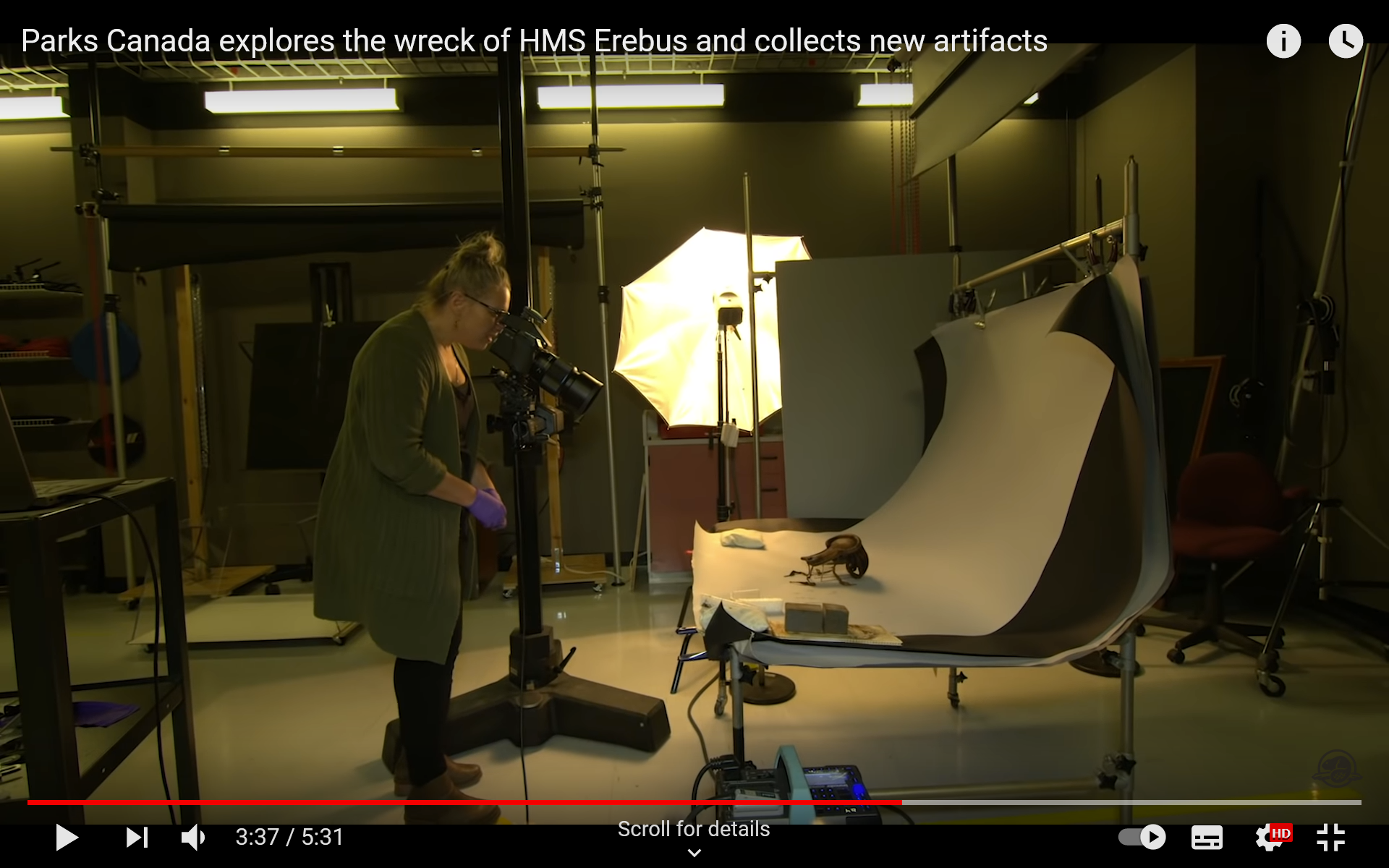
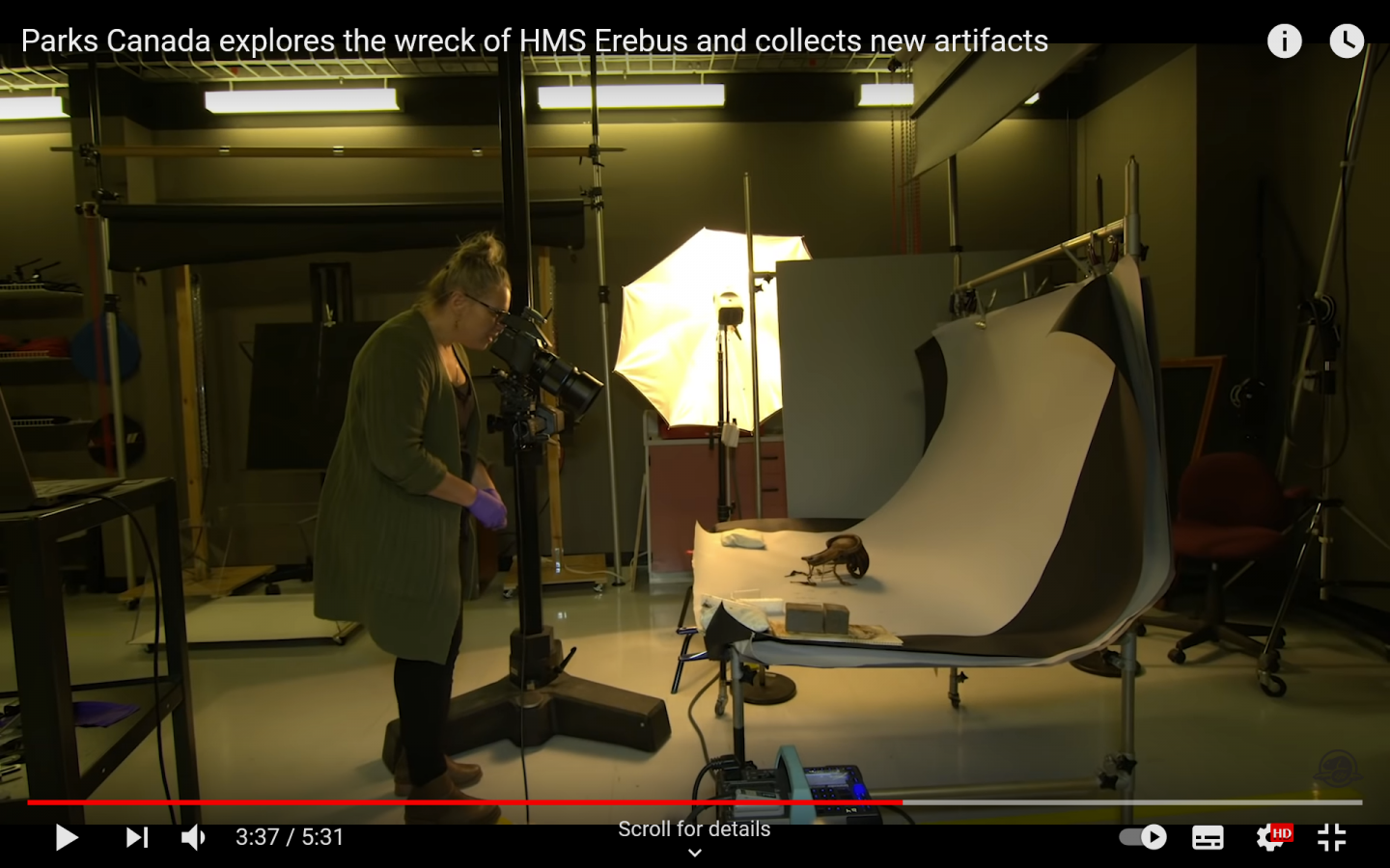
Whilst reading through Keith S' HMS Terror build ( https://modelshipworld.com/topic/23561-hms-terror-by-keith-s-occre-scale-175-as-she-disappeared-on-her-final-mission-1845-first-wooden-ship-build/?tab=comments#comment-693930 ) ... I saw mention of dives to inspect the ships' remains. So I went on a YouTube wander and saw this video where they are bringing artifacts to the surface, inspecting and measuring them and taking photographs.... 'GB Parks Canada explores the wreck of HMS Erebus and collects new artifacts' - https://www.youtube.com/watch?v=H33xOPlqrWQ At 3.37 mins in, we get a glimpse of the photographic set-up used to take the pictures Fundamentally, the set-up isn't that different from what a lot of the experienced members on this forum recommend. Richard PS: I've dicovered that on this side of the pond we spell it 'artefact' and on the other it's 'artifact'. 😉
-
Very educational. You're a dab hand at sketching with a pencil and a ruler. And the 'CNC' controlled milling machine for the counterbores was impressive 😉 Richard
- 156 replies
-
- 1
-
-
- marisstella
- marisstella model ship kits
- (and 4 more)
-
A lovely video on the new addition.... Richard
.jpg.5de37c13649c003d66ea7429361a9ee0.jpg)
.jpg.0111631f0410b0a41a51c5263af6354f.jpg)
.jpg.46bd3720ed6d063db5341cded4ce4923.jpg)
.jpg.a2d32efc28a3fe3c6851e7f9e69f2752.jpg)
.jpg.5c848f34b7ba0a8500d622795ab542e5.jpg)
.jpg.0a59c5aeec7c79bd8ef26e7db97ff0a5.jpg)
.jpg.4c30b0b8812a9c4750ef6011eab297dc.jpg)
.jpg.758408f7e8750e9067465db6a1139e6b.jpg)
.jpg.f013e559abb21315aceeed2ab9d9dcfa.jpg)