


AnobiumPunctatum
-
Posts
1,275 -
Joined
-
Last visited
Content Type
Profiles
Forums
Gallery
Events
Posts posted by AnobiumPunctatum
-
-
-
-
Really nice progress. I like the color of your stain
-
The color of the stain you used, is looking really nice.
Sorry to read about your problems with the hull shape. I hope you can solve the problem
-
-
It's a shame, that you planked the hull on both sides. So nobody will see your really nice frameing job.
Wonderful build
- Jeronimo, tadheus and giampieroricci
-
 3
3
-
-
-
-
-
I second Jürgen's wishes.
-
The frieze looks really good. Wow, I am really impressed.
That's exactly the appearance I like to get for my both models
-
-
Jürgen,
wouldn't it be easier to plank one side of the model and let the other perhaps until the whales unplanked?
-
-
Christian, thanks for looking in. Does Alert have any stern lettering? The same technique would be applicable.
Toni,
if I would follow the Marshall paintings, Alert has a frieze and a stern painting. But I will build my model with open sides, so I don#t know if I schould paint some frieze.
-
Thanks for the description, Toni. If I come back to my HMS Fly, I will have the same problem with painting the friezes.
-
@Mike
thanks for looking in. I use Autocad for the drawings.
@Nils
the frames are perpendicular to the keel and have an angle to the waterline.
Have a look at the NMM drawings of Cheerful 1806, Racer 1809 or one of the 1818 cutters. All drawings show this frame arrangement.
- Mirabell61, AntonyUK, Jaekon Lee and 1 other
-
4
-
Really nice progress, Lee.
Your build log is a big motivation, to work on the drawings for my build.
- Jaekon Lee, Dubz and Mirabell61
-
3
-
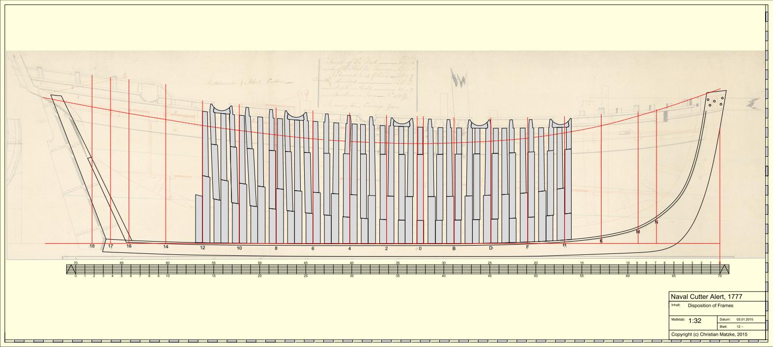
The design of the parallel frames is finished. I tried to follow the original drawing as close as possible without one change.
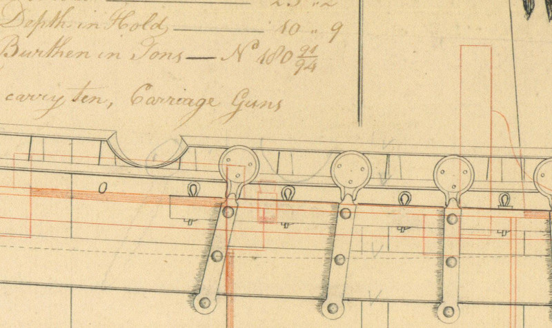
If you have a closer look at the gun port position of the original drawing you will see a pencil note, which indicates that there was added a 5th deadeye, which is not common for cutters. I did not know any other cutter drawing with more than 4 deadeyes.
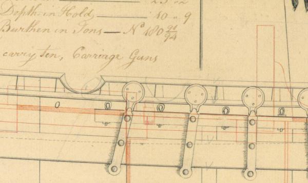
So I decided that I like to show this update of the original design - the Marshall drawing also shows 5 deadeyes. For this change I modified the gun port position and the top timber heads in this area.
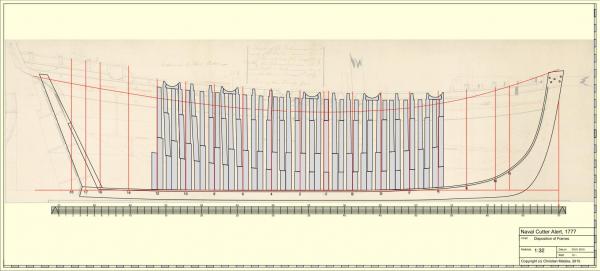
My biggest problem during the design was, that the gun ports and top timber heads did not match the position of the double frames. I could not solve this problem with using another design, so I decided to shift the futtocks as I've seen in some contemporary drawings.
If you compare this design with the known design of the Aots-book (I don't like adding a scan to avoid problems with Copyright issues) you will see that this design is much more rugged. The gunports ar not put on top of the framing as Goodwin did.
I don't know but I hope that it's a little bit closer to the original framing. If you think that I can optimize the position of some frames, please let me know. Next I start with the fore cant frames.
- jaerschen, qwerty2008, Jaekon Lee and 4 others
-
7
-
-
Happy New Year
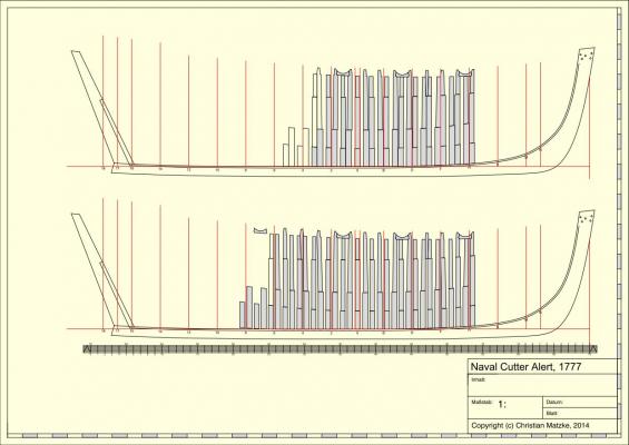
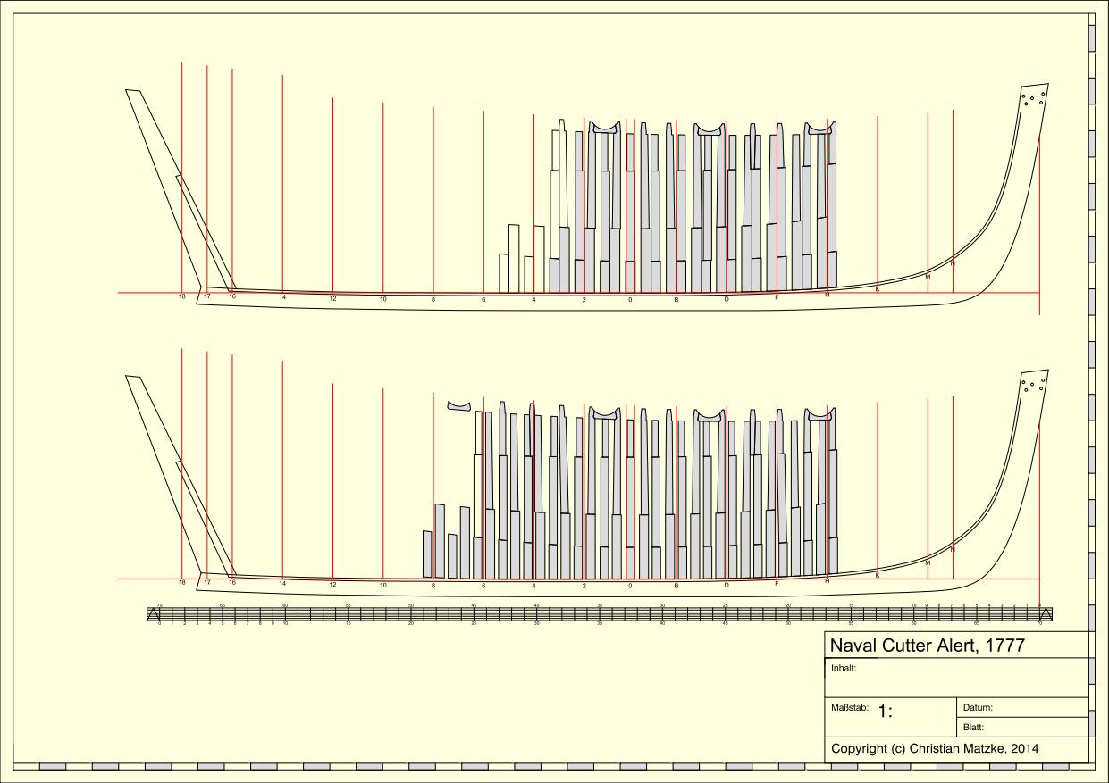
It's time for another short update. The design takes more time than expected. I notice that I don't have any experience in doing this. I reconstructed the square frames from station line H to station line 4 for both options.
I don't know which one could be right.
Both options have their advantages and disadvantages
Option 1:
+ The real double frames are more common than the design in option 2
+ The relationship of room and space is more common comparing with other (bigger) ships of that time
- The width of the floor timber given through the two station lines for station 0 does not fit.
Option 2:
+ The width of the floor timber fits two the station lines at station 0.
+ The frame design allows a better ventilation between the frames
+ The frame design is very light which is positive for a fast sailing ship
- The relationship of room and space is very uncommon
In my opinion the given historical dimensions for framing a cutter are not very helpful for a cutter of the Alert-Class
The shipbuilders repsoitory is from 1788 and Steel from 1805. There was a very important change in the armament of ships between the design of Alert and the two documents: the introduction of the carronades.
In the older repositories the cutters would not mentioned.
What do you think, which is the solution you would prefer?
- AntonyUK, tadheus, Jaekon Lee and 1 other
-
4
-
She has a really nice design and will be an interesting project.
-

HMS Pegasus 1776 by Trussben - 1:48 - Swan-class sloop based on TFFM
in - Build logs for subjects built 1751 - 1800
Posted
Ben,
really nice practice.