HOLIDAY DONATION DRIVE - SUPPORT MSW - DO YOUR PART TO KEEP THIS GREAT FORUM GOING!
×


AnobiumPunctatum
-
Posts
1,280 -
Joined
-
Last visited
Content Type
Profiles
Forums
Gallery
Events
Everything posted by AnobiumPunctatum
-
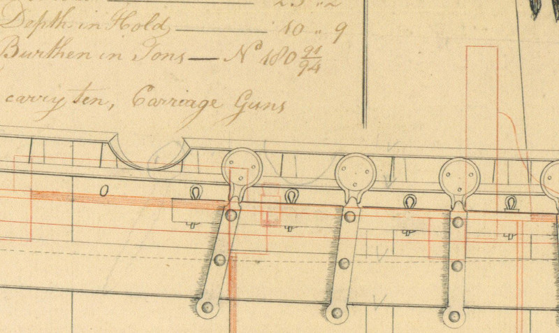
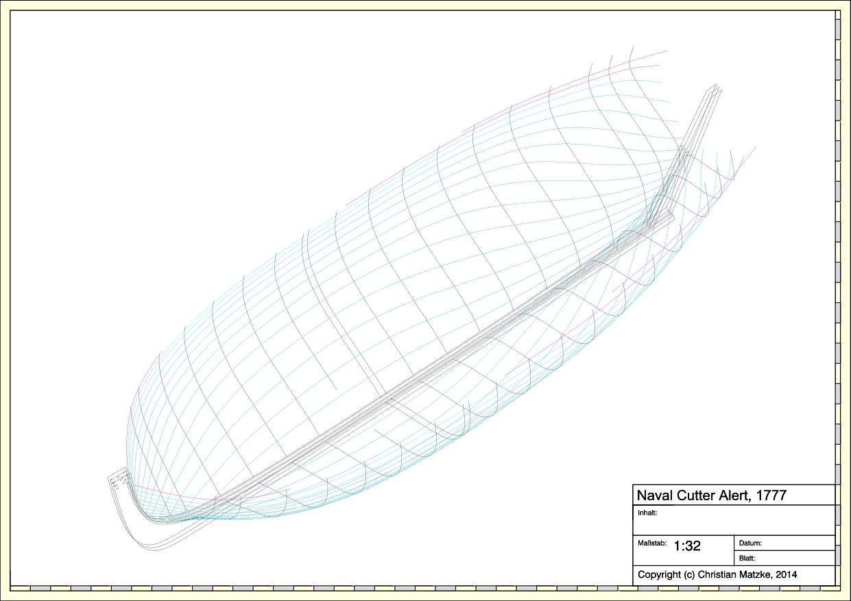
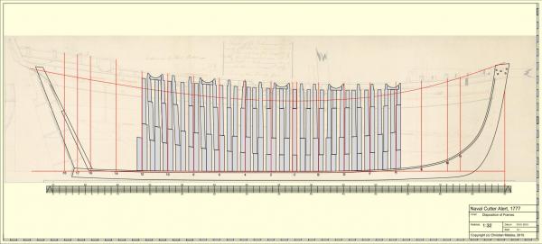
The design of the parallel frames is finished. I tried to follow the original drawing as close as possible without one change. If you have a closer look at the gun port position of the original drawing you will see a pencil note, which indicates that there was added a 5th deadeye, which is not common for cutters. I did not know any other cutter drawing with more than 4 deadeyes. So I decided that I like to show this update of the original design - the Marshall drawing also shows 5 deadeyes. For this change I modified the gun port position and the top timber heads in this area. My biggest problem during the design was, that the gun ports and top timber heads did not match the position of the double frames. I could not solve this problem with using another design, so I decided to shift the futtocks as I've seen in some contemporary drawings. If you compare this design with the known design of the Aots-book (I don't like adding a scan to avoid problems with Copyright issues) you will see that this design is much more rugged. The gunports ar not put on top of the framing as Goodwin did. I don't know but I hope that it's a little bit closer to the original framing. If you think that I can optimize the position of some frames, please let me know. Next I start with the fore cant frames.
-
Thanks very much for your reply, Druxey. I will follow your advice and finish option 1. You confirmed what my gut instinct said.
-
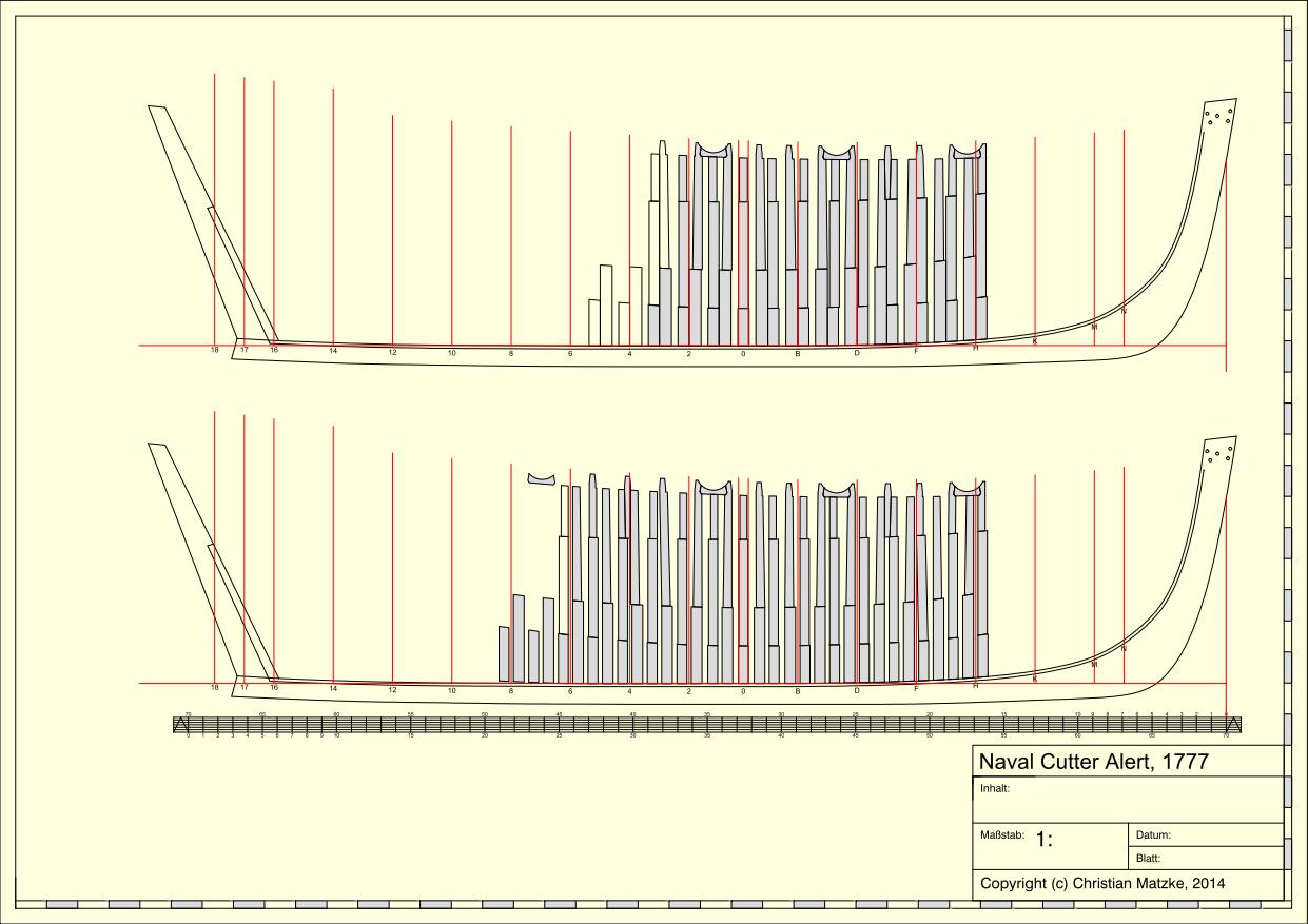
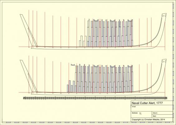
Happy New Year It's time for another short update. The design takes more time than expected. I notice that I don't have any experience in doing this. I reconstructed the square frames from station line H to station line 4 for both options. I don't know which one could be right. Both options have their advantages and disadvantages Option 1: + The real double frames are more common than the design in option 2 + The relationship of room and space is more common comparing with other (bigger) ships of that time - The width of the floor timber given through the two station lines for station 0 does not fit. Option 2: + The width of the floor timber fits two the station lines at station 0. + The frame design allows a better ventilation between the frames + The frame design is very light which is positive for a fast sailing ship - The relationship of room and space is very uncommon In my opinion the given historical dimensions for framing a cutter are not very helpful for a cutter of the Alert-Class The shipbuilders repsoitory is from 1788 and Steel from 1805. There was a very important change in the armament of ships between the design of Alert and the two documents: the introduction of the carronades. In the older repositories the cutters would not mentioned. What do you think, which is the solution you would prefer?
-
She has a really nice design and will be an interesting project.
-
Really wonderful pictures Ed. I will also by a copy of this book. I like the Tea Clippers and your model will be a fantastic possibility to build one in the future
- 3,618 replies
-
- 1
-

-
- young america
- clipper
- (and 1 more)
-
Hi Giampieroricci, I've take the time to look through your complete build log. It's a real interesting log and a nice representation of the "French shool of shipmodelling". I'll follow your log next year with great interest
-
Really nice progress
-
Really nice drafting skills. I like to see more of your drawings.
-
Seventy degrees Fahrenheit. I don't knowhow much this in °C is, but I think it's very hot. In Germany we have around 0°C. Best weather for working on my model drawings. Have you thought of using different colord timbers for framing and planking the model? Or do you like to paint your model later?
-
Aldo, it's good to hear from you. I am happy that you are doing better and find time to continue your log.
-
Mery Christmas, Jürgen. Your Triton looks really good
-
Wow, really wonderful small Modell. It's unbelievable that's build of wood.
-
Wow, that's a really beautyful planking. Do you like to copper her?
-
Back to the framing dimensions. I got the values of the SR, but there are mostly the same as in Steel. But both dimensions are for a 273 tons, 16 gun cutter which is much bigger than Alert. I also got the values for Weazle, a 201 tons brigantine, which is nearly the same size as Alert and has the same room and space. (Thanks very much for the help) Unfortunately the framing dimensions do not really fit with the proportions of SR and Steel. So I decided to go with two different options: 1. On the basis of Steel I calculated the relationship between 2'2'' and 2'0'' room and space and make my frames 92.3% of the dimensions of Steel. 2. I use the given distance between the station lines for frame 0 (8'') and calculate all other timbers in relationship to Steel. The first design I will do with option 2 and the frame layout of Cheerful and Racer. These drawings are around 30 years younger but the oldest which I found with framing information. If the design don't work, I will give the first option a try with real double frames. What do you think, could both options a possible solution for the framing of the small vessel? Which option would you prefer?
-
Very interesting solution for keeping your fingers away from the blade. Did you made this by yoursel?
-
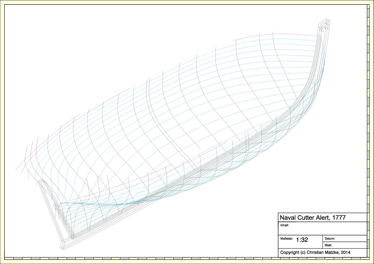
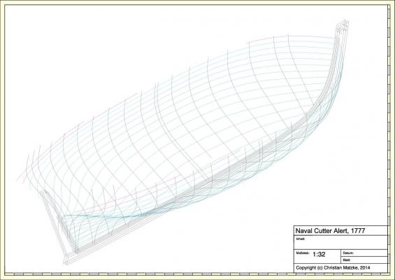
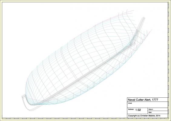
Yesterday I experimented a little bit with 3D views of my line drawings. The result is not a real 3D model but very helpful for checking the reconstruction. The two pictures are only an impression, because on the PC I can rotate the model and have a closer look to the details.
-
Ben, Allans book is on my wishlist for Christmas.
-
The framinglooks really well aligned. Superb work, Ben
-
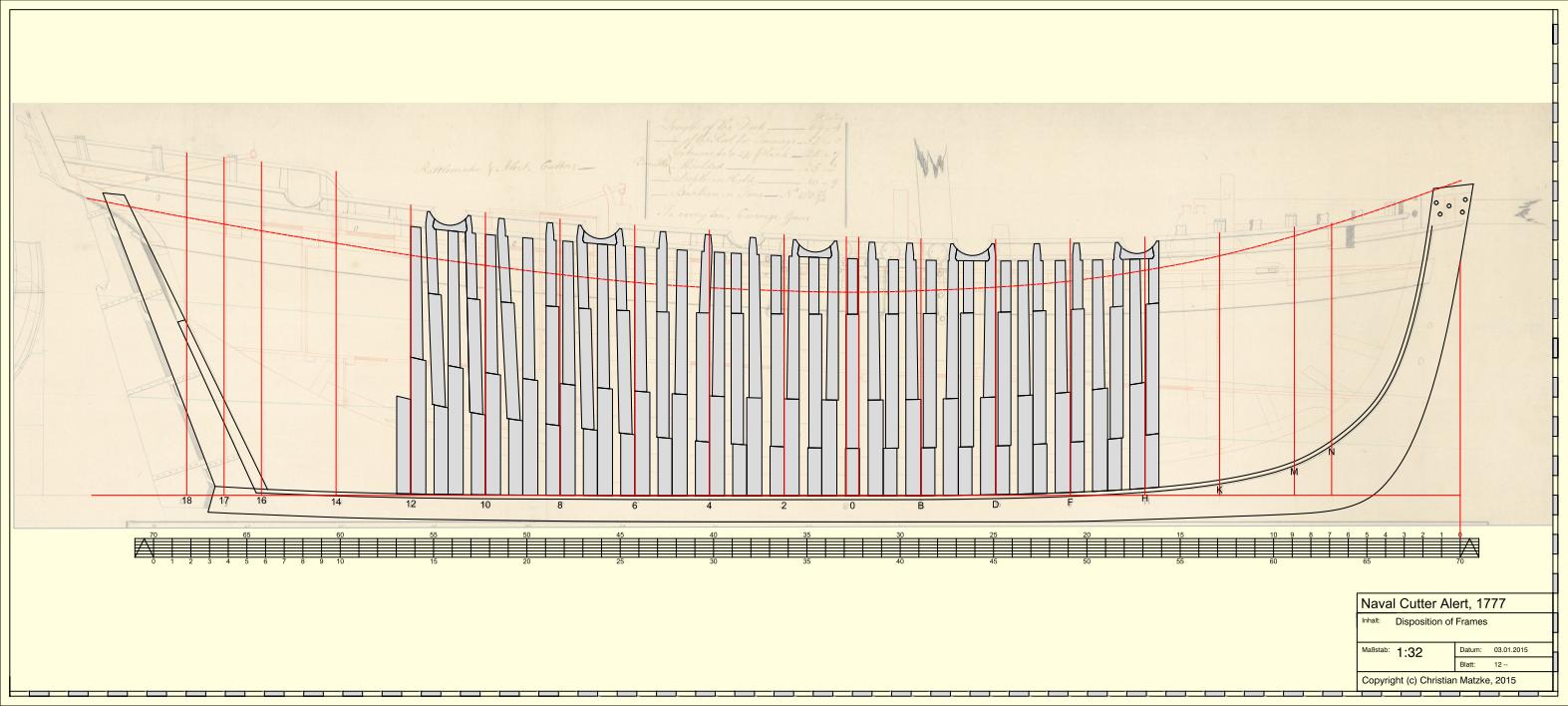
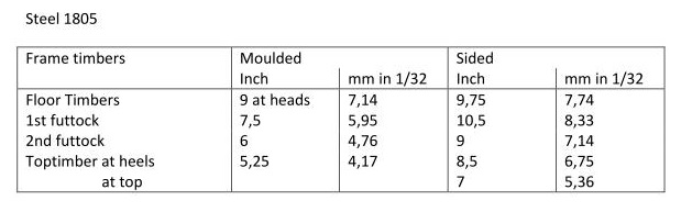
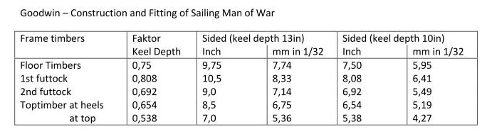
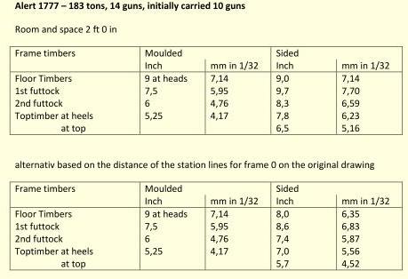
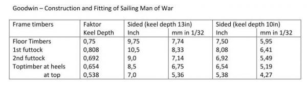
My stylised frame design is nearly finshed. As written in JK Lees build log I will now try to design a possible framing for this cutter. All cutter drawings which I know show only double frames. The drawing of Cheerful 1806 and Racer 1809 show double frames with a spacing on both sides. The drawing of Speedy 1818 shows normal double frames. So I think that also the two cutters of the Rattlesnake class will also have only double frames. First source for the dimensions of the frame timbers is Steel "The Elements and Practice of Naval Architecture, 1805": (Thanks Druxey for the values) Steel gives a Room and Space of 2ft 2in. The original drawing of Alert only show a Room and Space of 2ft 0in. My first try with this dimensions show that the spacing between the double frames is very small (3.75in). Goodwin gives in his book "The construction and fitting of Sailing Man of War" a factor to calculate the sided dimensions of the frames. If I calculate the sided values with the keel width of 13in, which Steel gives in his book, I get the values of the above table. The original drawing shows only a designed keel width of 10in. So I calculated the sided dimensions of the framing again. With these values I get a spacing of 8,42in, which is perhaps a little much. edit: I got the infos I searched. Thanks very much.

-
Lee, as I've written earlier I think that the frames design in the AotS is wrong. The shifted top timbers are only a fix for this design. Also the positions of the gun ports don't match the position of the original drawing. I could only find double frames for cutters. If I read Allans comment he confirmed what I think. There exist no contemporary drawing of the framing design for the Rattlesnake class. I've drawn a simplified framing but will now try to make a new reconstruction of the framing to check if my ideas are possible.
-
Wonderful. That looks really perfect.
-
Tony, there is not really a problem. I buy my timber at a supplier in Germany, who cuts it to every size with a precision of 1/10mm. I think that this is precise enough for a scratch build model. http://www.modellbau-holzleisten.de/
- 1,051 replies
-
- 1
-
-
- cheerful
- Syren Ship Model Company
- (and 1 more)
-
Thanks for posting the pictures. That helps me a lot. I don't think so. I found hints on it at my Alert drawing, on the drawing of Racer 1808 and on the Speedy drawing of 1818. If a kit does not show this detail it's not a reason that it was not there.
-
Nice fix, Jürgen