HOLIDAY DONATION DRIVE - SUPPORT MSW - DO YOUR PART TO KEEP THIS GREAT FORUM GOING!
×


AnobiumPunctatum
-
Posts
1,280 -
Joined
-
Last visited
Content Type
Profiles
Forums
Gallery
Events
Everything posted by AnobiumPunctatum
-
Found your log this morning. Really wonderful. I'll follow your log with great interest
-
Grant, welcome to the very dark side of model building. I am sure you will have a lot of fun with your build. So you never find back the way to the other side
- 456 replies
-
- 1
-

-
- finished
- bomb ketch
- (and 2 more)
-
looks really good, Kevin
-
Congrats for reaching this milestone, Jürgen. Your hull looks really impressive. I am nosey to see your hull when we meet next year .
-
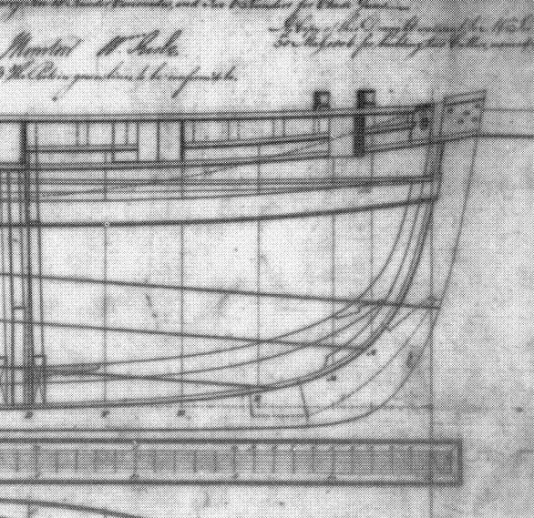
Thank you for posting this part of the Cheerful drawing, Chuck. This detail was not to identify on the small picture I have. You confuse me. The Alert is from 1777 and I thought that the Cheerful is from 1806.
-
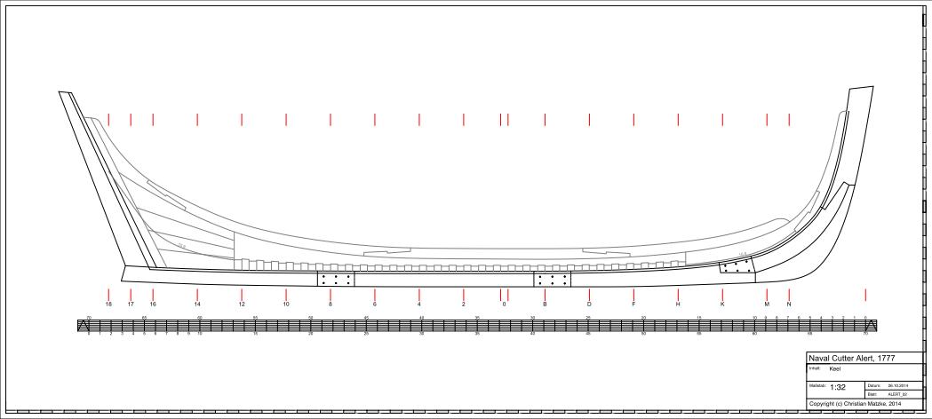
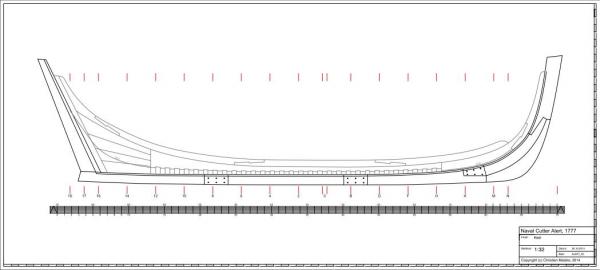
Here is the modified drawing.
-
Thank you, Druxey. I will follow your advice and modify my drawing. Your input is the reason, why I post my drawing, because I am sure that there are things which can be done better. And so I am very happy that you show me possible improvements,
-
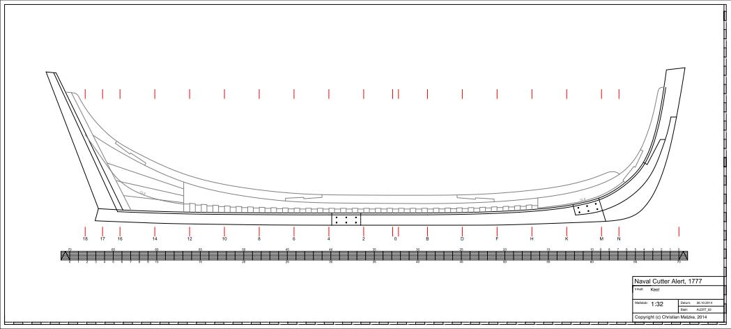
Thanks for the hints, Druxey. I found this solution for the stem joints at a contemporary drawings of HMS Cheerful, 1806. Do you think that the drawing has there a mistake? I will change the numbers of joints at the keel.

-
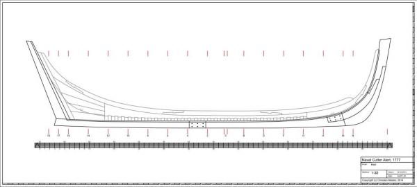
My new keel drawing is finished. Next I will draw the frames and build the new bigger version of my keel
-
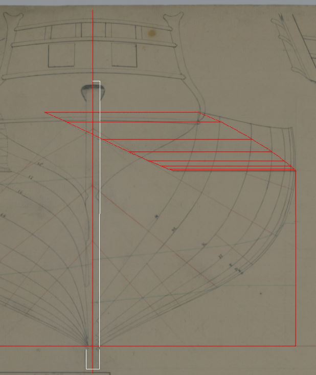
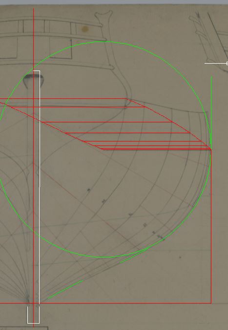
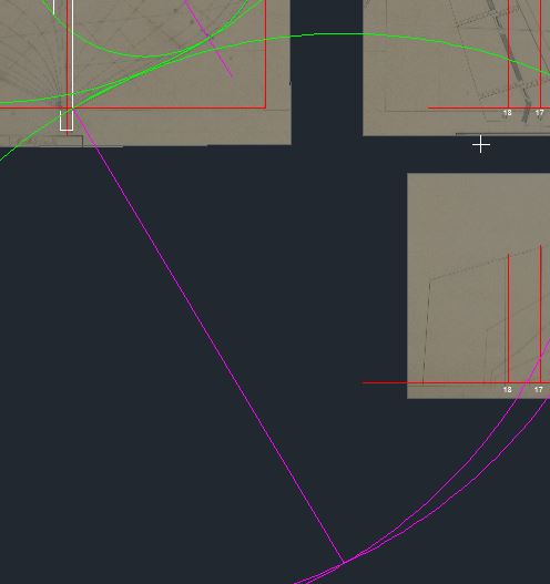
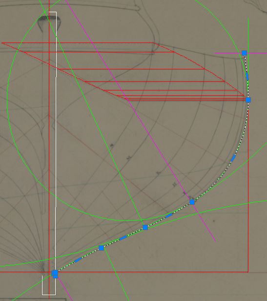
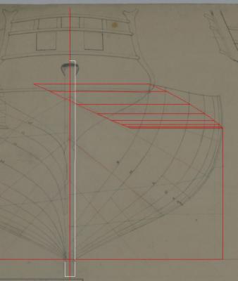
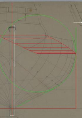
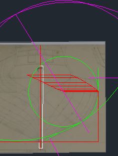
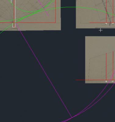
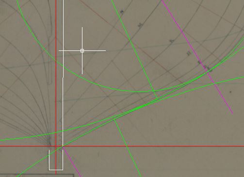
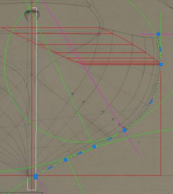
Daniel asked me to show how I get the different center points and radii for the construction of an frame. Please be in mind that there are a lot of other steps necessary before you can start with the frame construction. First let me refer to two articles which I think that they are very helpful in understanding the lines of an original drawing 1. David Antscherl: Understanding Eighteenth-Century Admirality Drafts, Nautical Research Journal Vol. 52, No. 2 Summer 2008 2. David White: Understandig Ships' Draughts, Model Shipwright No. 48 ff. I made some screen shots during the construction of the main frame of the cutter. After creating the "Breath Extreme" line in the Body-Plan, I define the Center Points for the Lower Height of Breath. Next I determine the radii of the arcs, which don't have the center points in the original drawing (most of this arcs were drawn with French Curves). The list gives the different values: Lower height of breath: 72.53 first: 260.35 second: straight third: -319.9 Next I calculate the center point of the first curve: I draw an arc with the radius 260.35 from the endpoint of my help line and a radius from the center point of the lower height of breath withe the radius 260.35 - 72.53 = 187.82. Then I draw a line from this center point to the center point of the Lower height of breath and stretchit to the circle of the Lower height of breath. Now you can draw a circle with the first radius. Now I repeat these steps for creating the center point of the third curve. I draw to circles with the determined radius, one from the keel and one from en point of the help line. Next I draw a straight line to both circles. There exist an Autocad function to do this, so nothing to construct for me . At last I draw the frame. I start at the Lower height of breath. Then I draw the upper height of breath and complete the frame with the other arcs and straights. I hope that this small description is helpful for someone.
-
Really wonderful. Can you give some descriptions, how do you paint the frescos?
-
Antony, I found your log today. Your section looks really wonderful. I love these big scales
-
Really wonderful, Mike
-
@Antony Thanks for the info. @Daniel I've scanned the NMM-drawing and work with the digital copy in Autocad. There I can take the measurements of all lines much easier than by hand. Also it's possible to get the information of the radii of the different curves. Be aware that the original drawing has some distortion which you have to calculate out. The diagonal and horizontal lines in the half breath except the breath extreme line are the result of the construction work in the body plan. There I use splines. All curves in the body plan are arcs with tagential transition. I will try to describe what I did, but it's not so easy to do in English. So please give me bit of time.
-
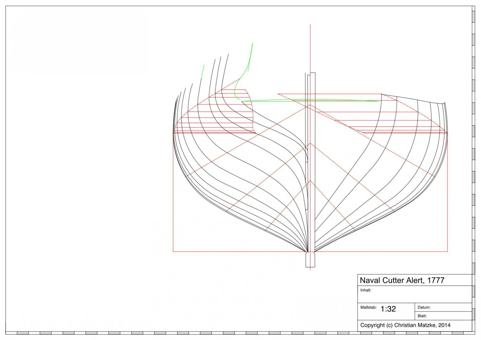
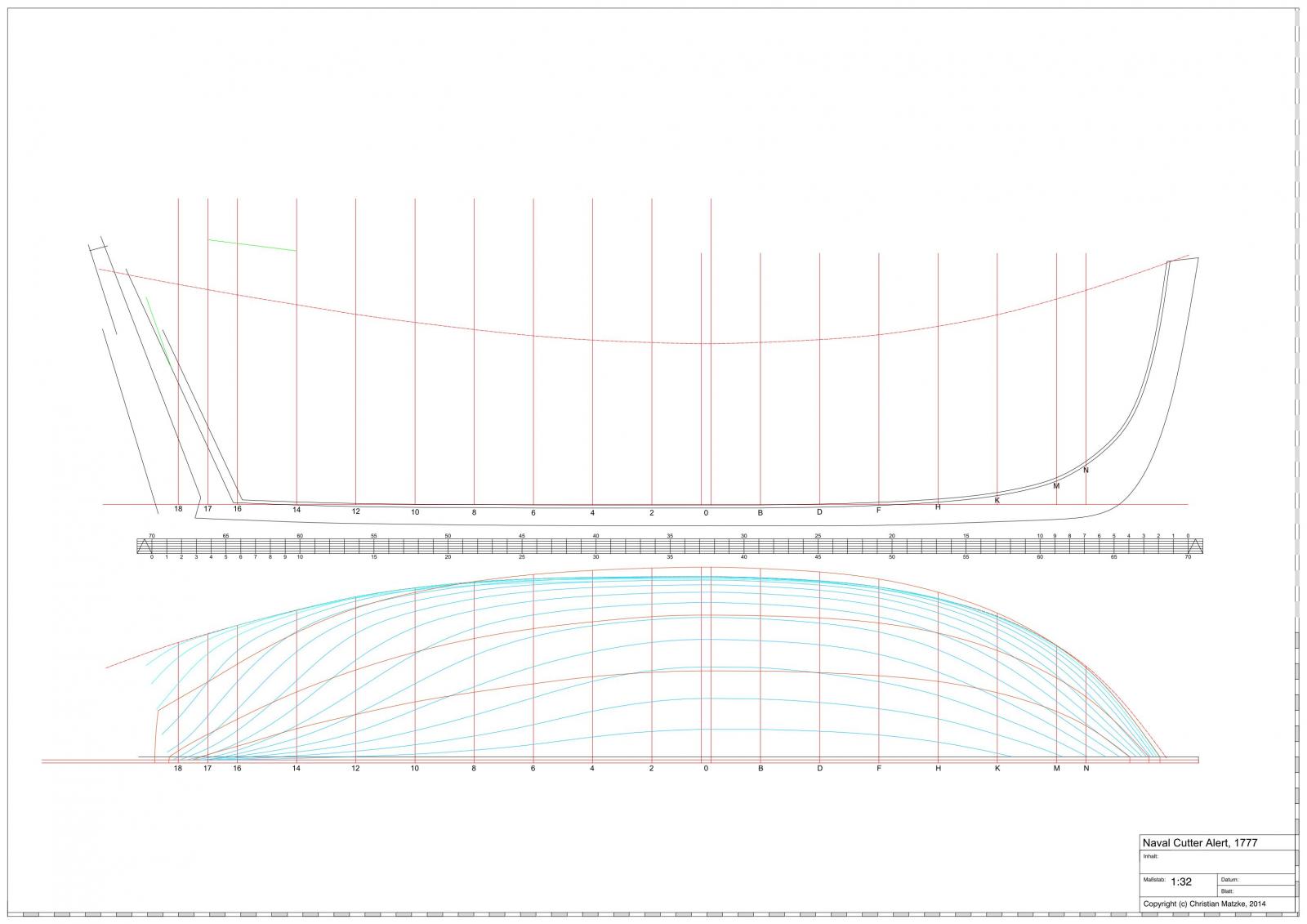
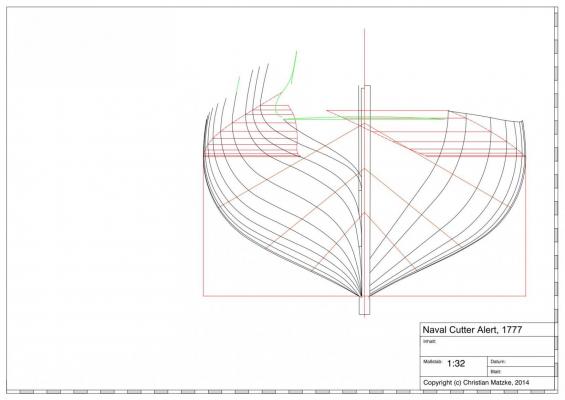
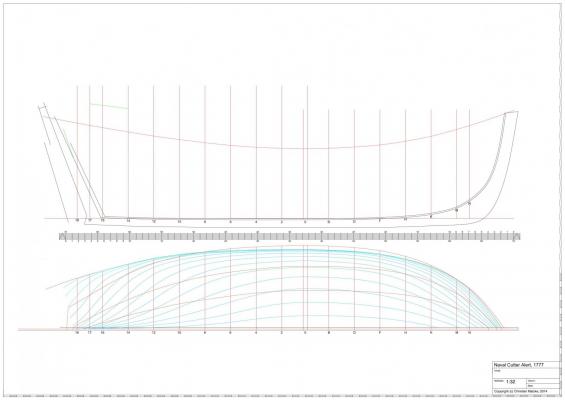
As written in my last post I bought last month the design drawing for Alert/Rattlesnake at the NMM. With my new knowledge about reconstruction of a line drawing I started to redesign the ship on basis of the NMM drawing. For this I did not use any information of Goodwin, because it's not a primary source. I don't have access to the archieves so I will only use the NMM drawing and later the vademecum for the scantlings. I am not sure if I like to show my model as designed and shown on the drawing or as shown on the Marshal painting. Both presentations have the same origin: they should show the design for a ship to the people who allocate the funds. The drawing isn't finished but I like to hear your meaning about the the reconstructed lines: It#s my first reconstructed ship, so I am not sure if everything is right.
-
Really wonderful progress, Jürgen.
-
Your new cannons are looking much nicer than the kit ones
-
Congrats for reaching this milestone. Your model is looking really nice.
-
There are some very interesting items on the agenda.Damned that Germany is to far away from St. Louis
-
This book looks like a good Christmas present for myself
-
Christian, as Mark has written, you can follow Goodwin in this detail for your model
-
Really wonderful windlass. This is one very tricky part and you make to look it so easy.
- 1,051 replies
-
- 1
-
-
- cheerful
- Syren Ship Model Company
- (and 1 more)
-
Hi Daniel, very impressive progress in the last month
-
Andy, the kit and most models of this beautyful ship are based on drawings from Höckel or Quinger. Quinger published a book in the 70th of the last century. I don't know if there exist an English translation of the book.
-
Chuck, very intresting build log. I will follow with great interest.
- 1,051 replies
-
- 1
-
-
- cheerful
- Syren Ship Model Company
- (and 1 more)