


Josh Williamson
-
Posts
117 -
Joined
-
Last visited
Content Type
Profiles
Forums
Gallery
Events
Posts posted by Josh Williamson
-
-
Nice job once again, Tom! Always impressed with the clean work. Cool choice with the hull paint - seems like that will give the model a nice, period-authentic character. Can't wait to see more
-
-
21 hours ago, MrBlueJacket said:
A general word of caution:
Using tea or coffee to stain cloth is not good for longevity. The acids in them will very slowly degrade the cloth.
Nic - perhaps you can help with a question I have:
I am looking for some information or photos of where the jib sheets lead to on Spray. The plans show them leading along the deck to about midships. I am assuming there is a location towards aft (probably near helm) that would enable Slocum to adjust from an aft position?
Thank you,
Josh
-
6 hours ago, MrBlueJacket said:
A general word of caution:
Using tea or coffee to stain cloth is not good for longevity. The acids in them will very slowly degrade the cloth.
Advice heeded! Thanks Nic.
-
Getting caught up on the last week of the build (worked 3 days for a couple hours each day). Focused primarily on the mizzen sail, and developing some standard work for working to the larger sails.
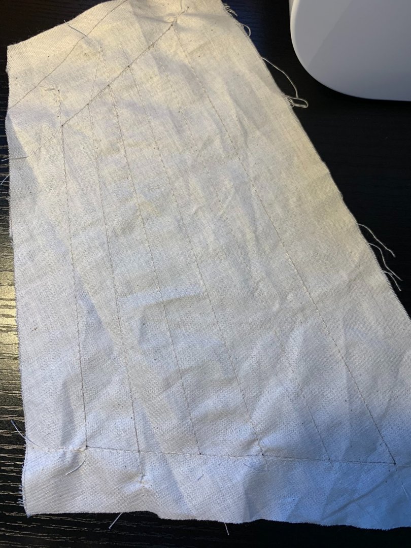
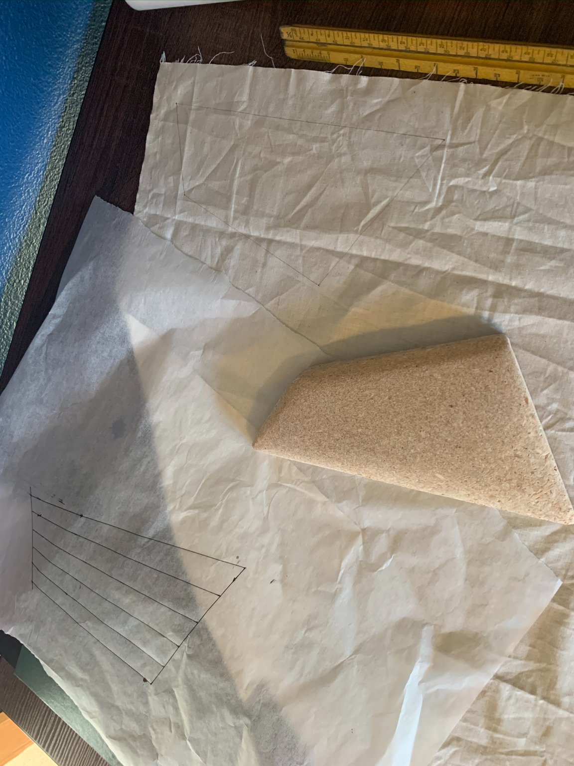
1) Having not spent much time behind a sewing machine, I thought it would be good to do a small test sail before moving forward with the actual mizzen sail. Also, I wanted to try staining the sail material with some diluted black tea to give it a more aged look (in the end, decided that this wasn't necessary as the sail material already has a nice warm tone).
Further, I made a decision that in the model's final form, I wanted it to look like it was sailing... So, I needed to make some decisions: Firstly, I decided that in the mounting cradle, the ship would be facing to the left (sailing westward when placed in my office). Wanted to be able to see the boom and majority of the deck when viewed, so it would have to be on a port tack. So decision made! : sails will be set for close-hauled, port tack (or something in that range).
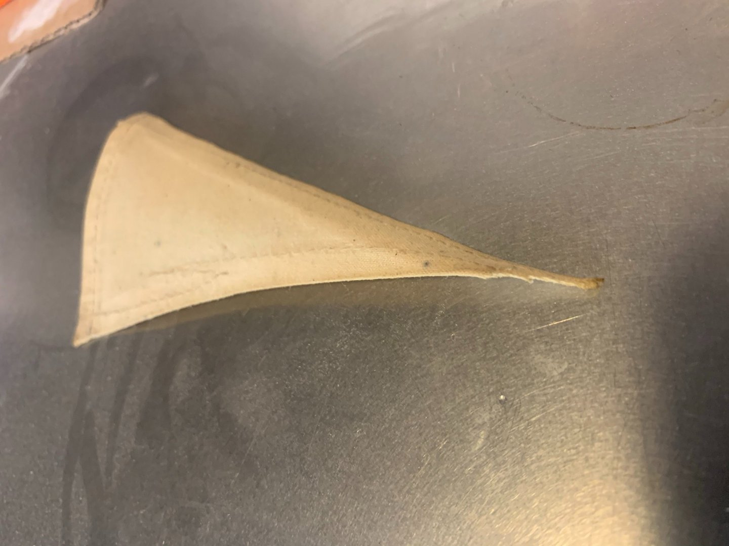
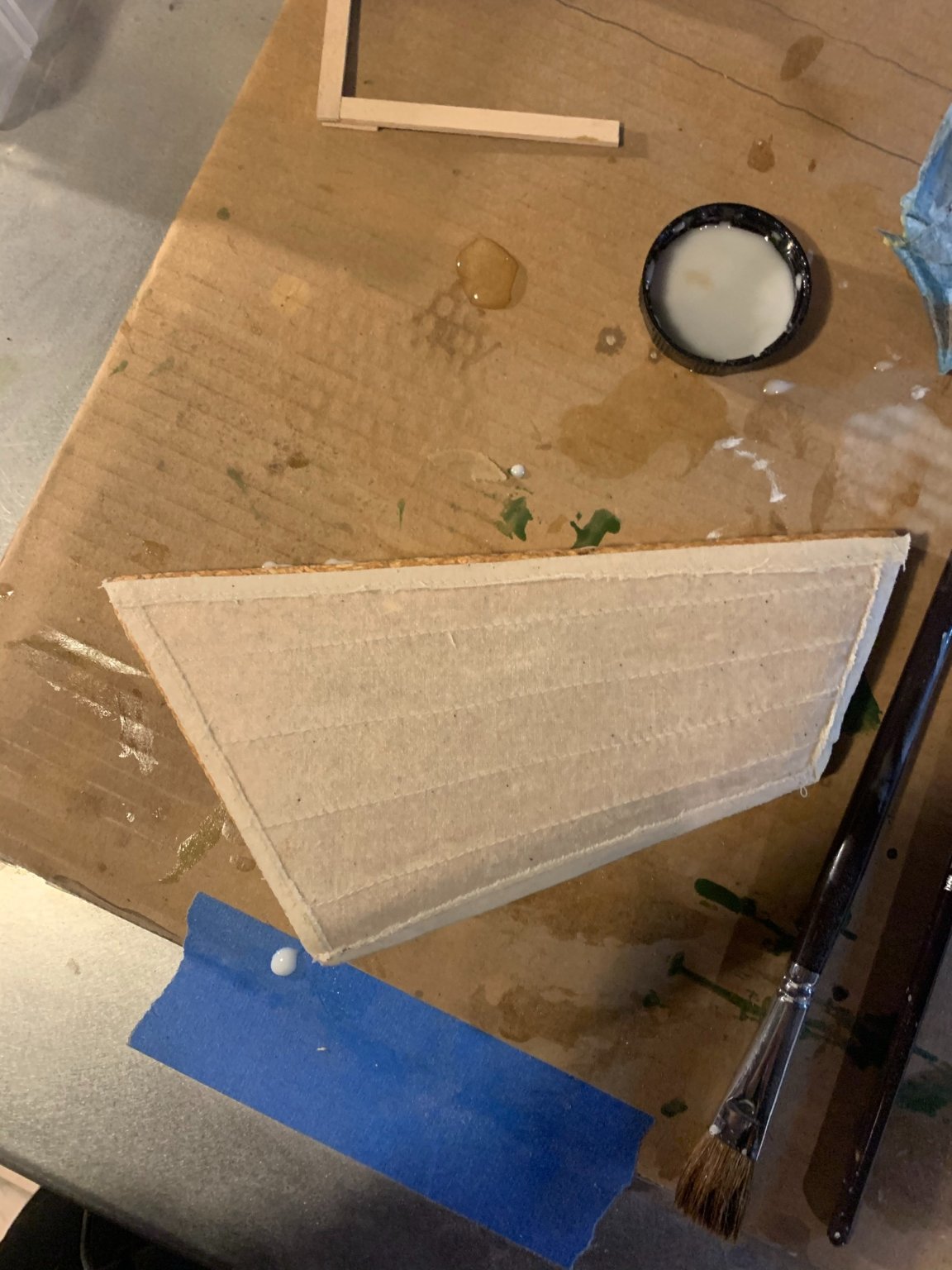
I have seen some blog posts of other modelers that have given the sail a nice full shape by shaping blocks and applying a diluted glue solution to the sail, then allowing to dry. Below is the small test sail I made, and the result thereafter with the dried sail. It seems to have worked well.

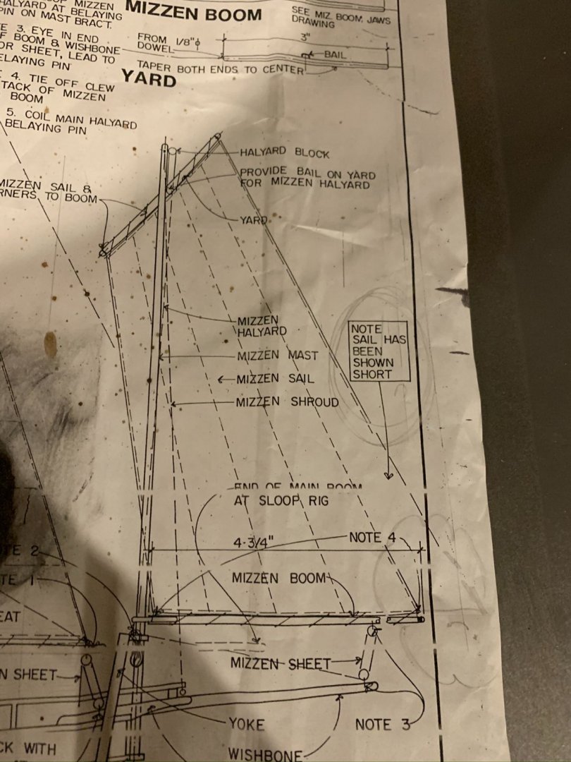
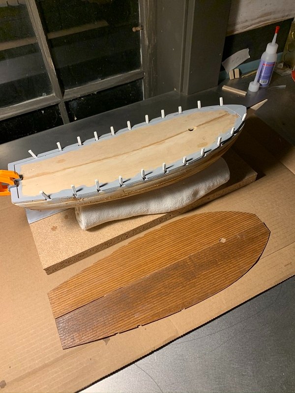
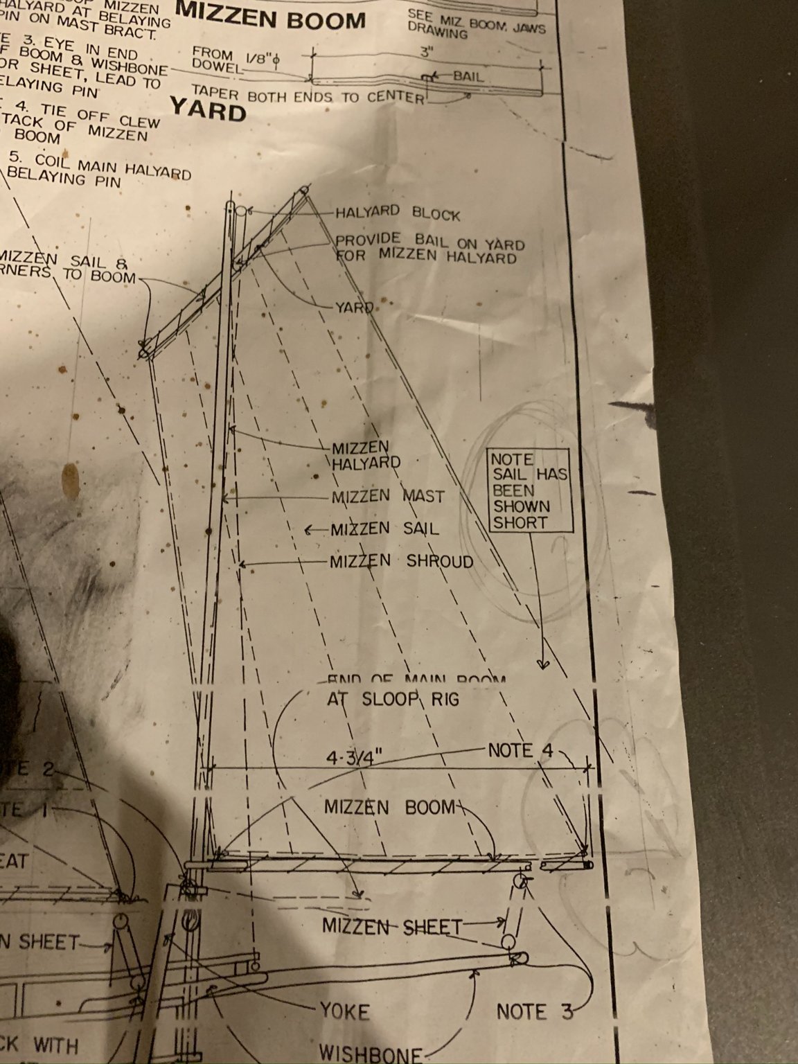
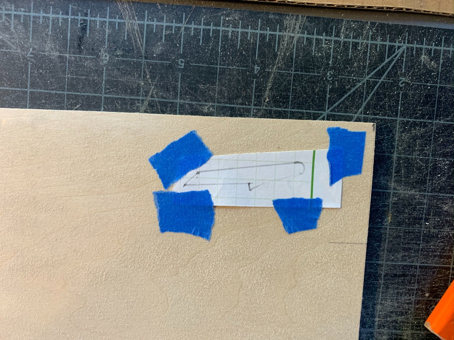
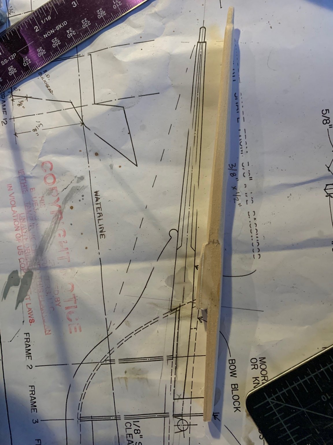
2) Tests complete, I went about tracing the shape of the mizzen sail (note that the plans show a shortened sail foot and mizzen boom in order to fit on the page. You need to continue the line of the leech downward to get the actual shape).
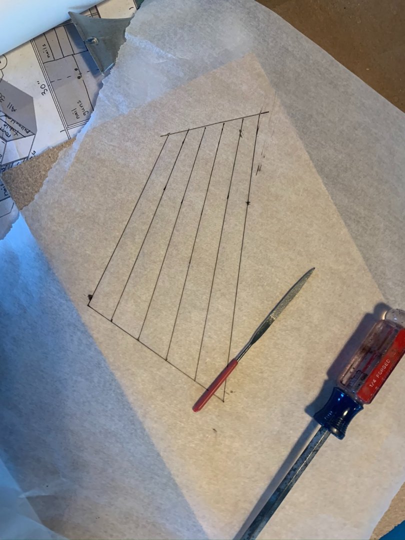
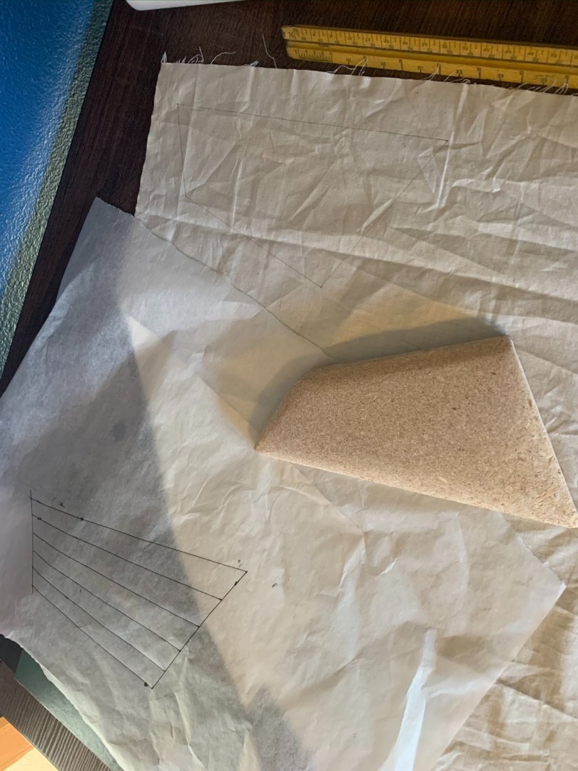
3) I transferred the sail geometry to a piece of plywood and cut that out using a skilsaw. Taking some time to sand down the edges with an orbital sander, was able to generate a curved sail shape. Below, the shaped plywood form, outline on sail material, and original sail plan traced to sketch paper.
3)
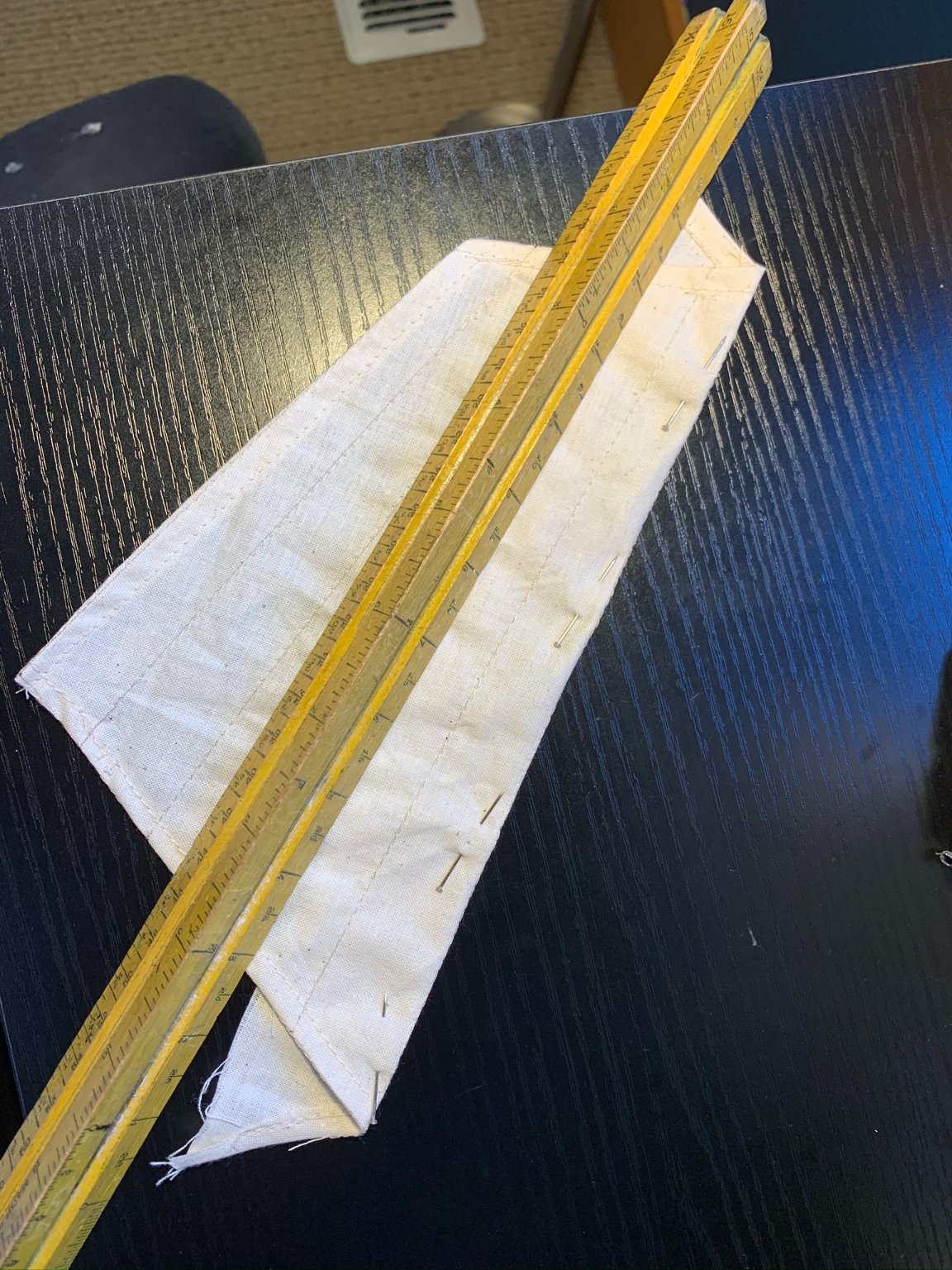
4) Using a very thin pigment liner, traced the outline of the sail, a seam margin for overlapping and sewing the edges, and the reinforcement points. Did some more tests with stitch width to give the appropriate stitch scale, and then started on the reinforcing seams of the sail...
5)
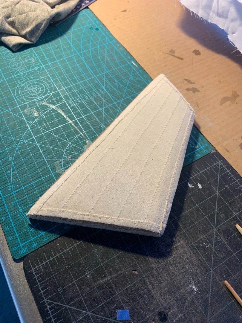
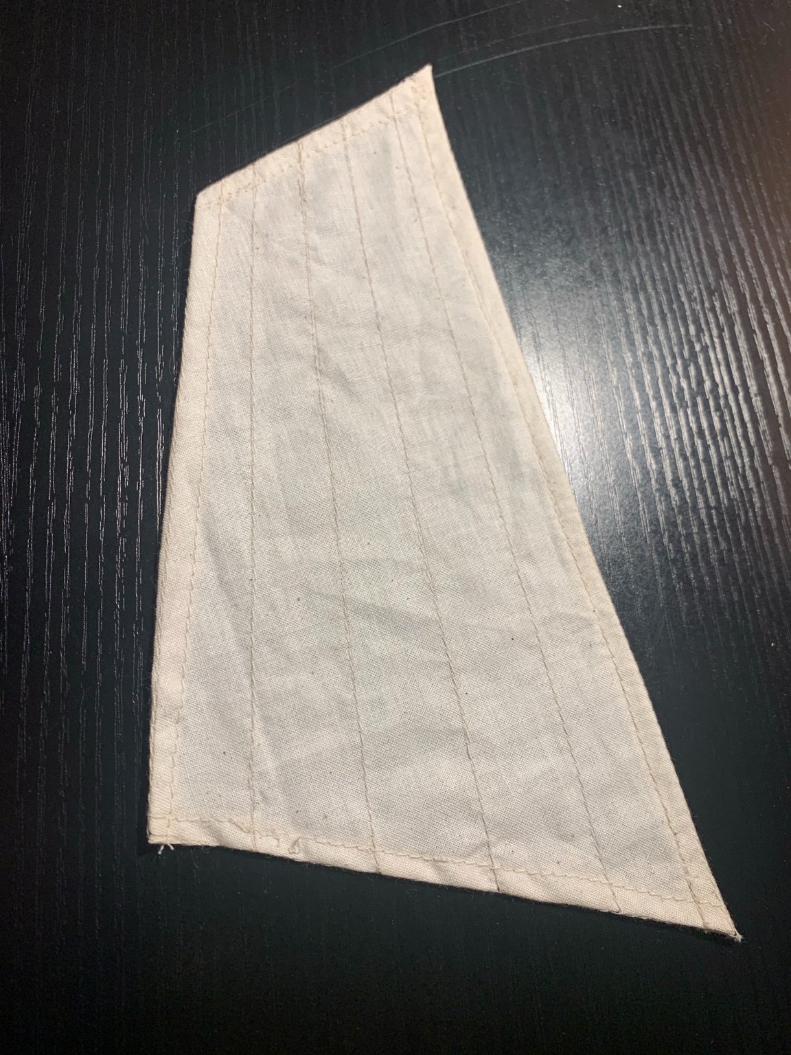
Here is the final result after sewing complete.
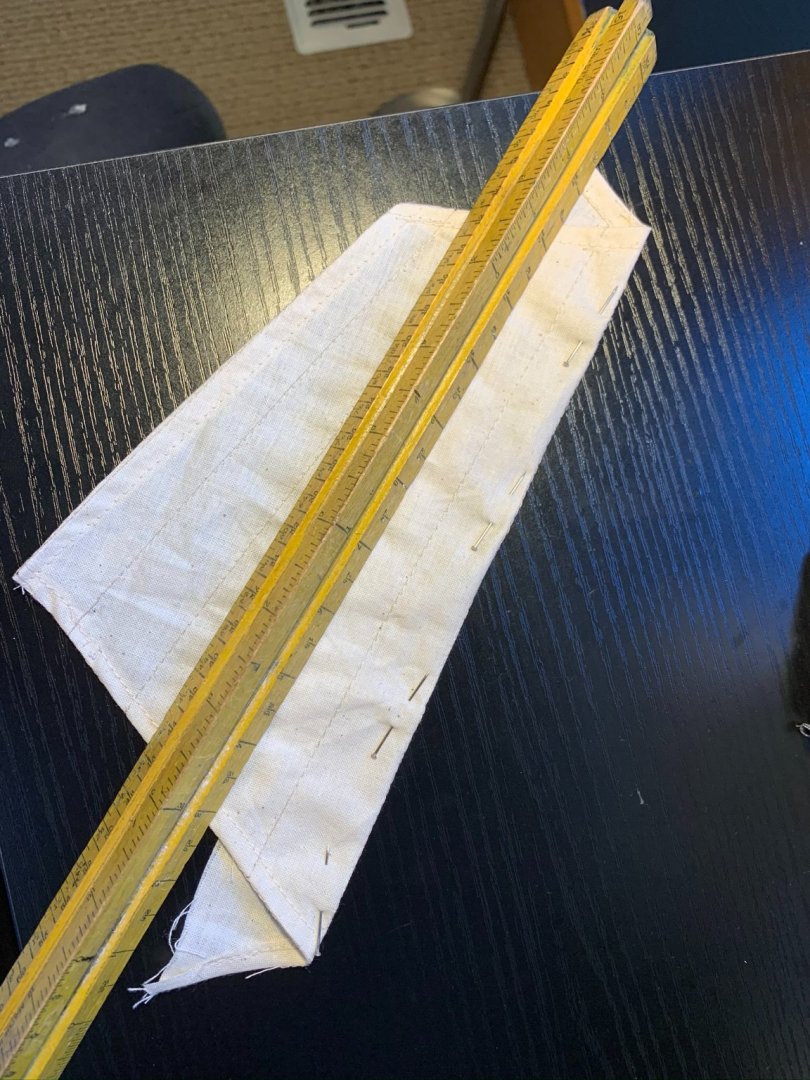
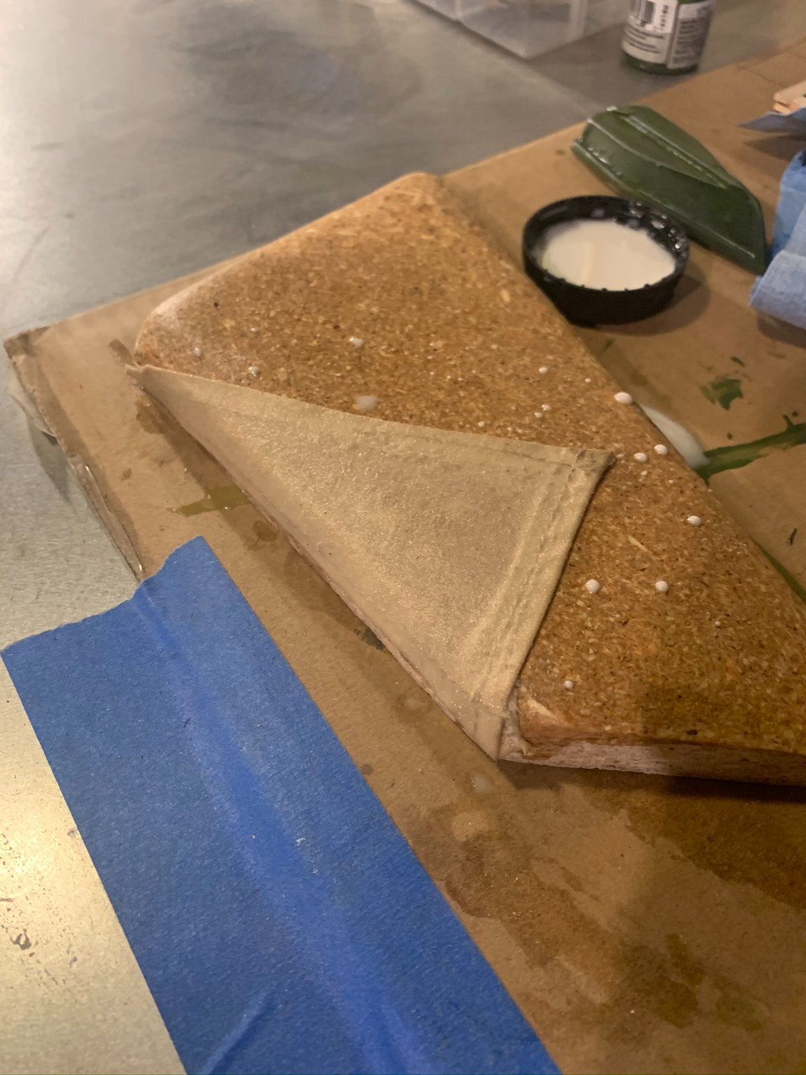
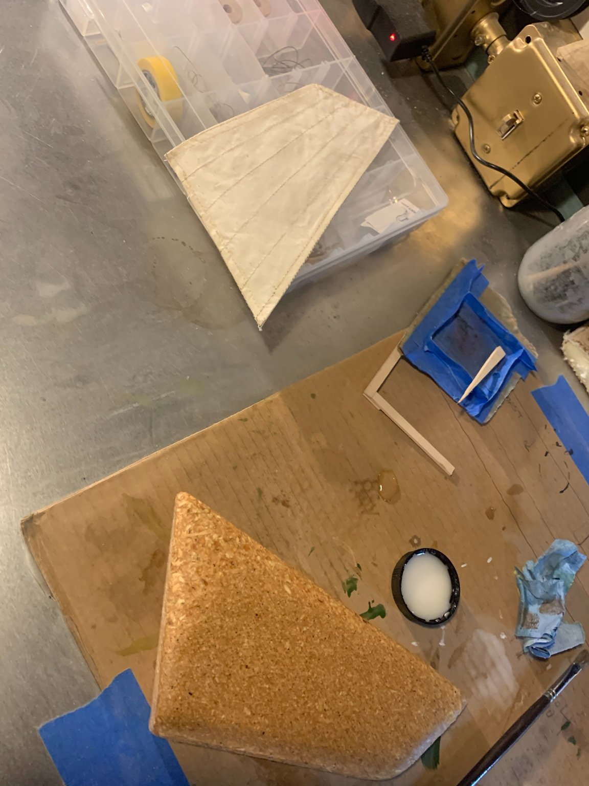
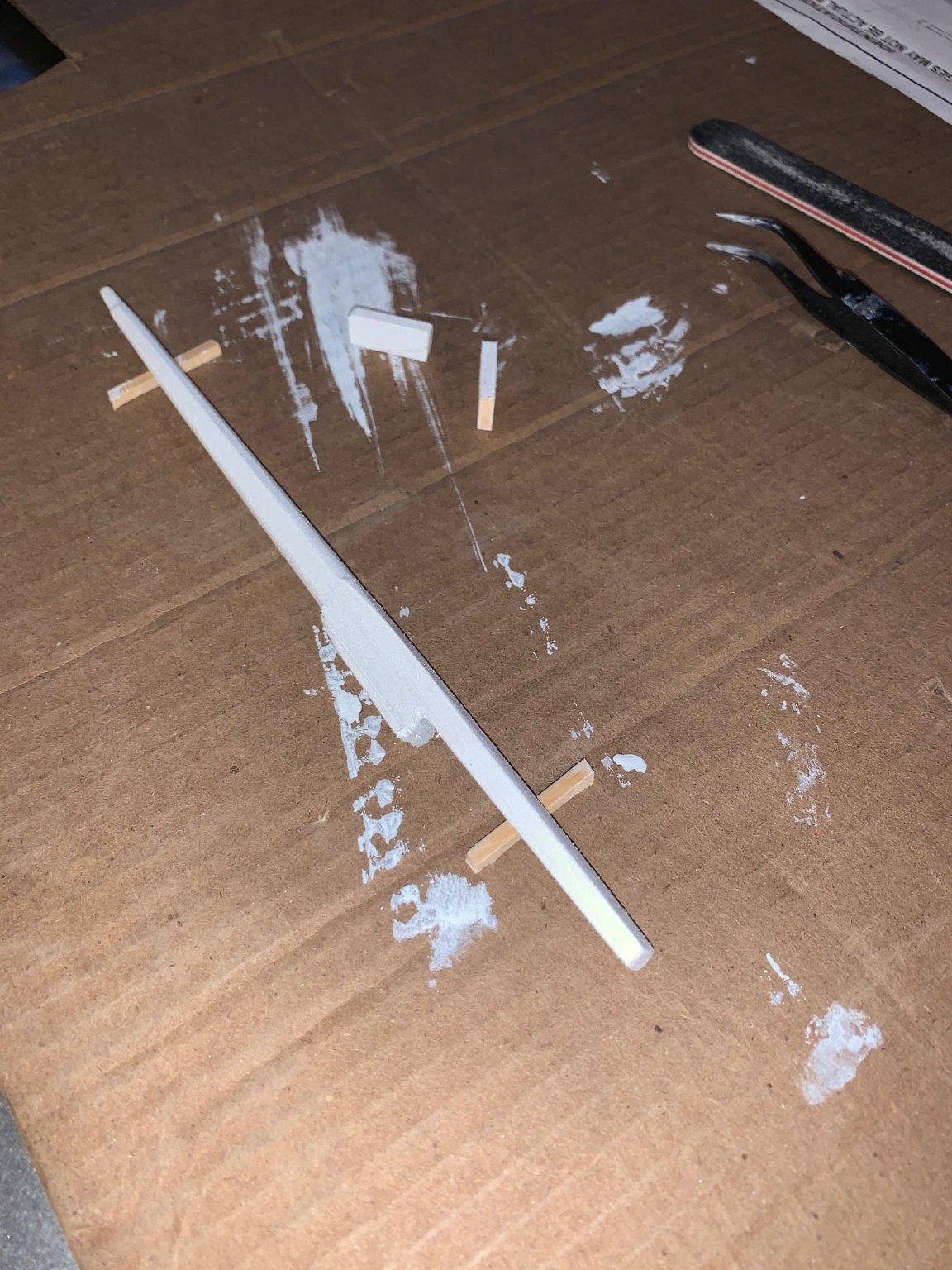
5) The form block was made from plywood (Note: the cutout is actually the mirrored image because on a port tack the sail is a concave shape if looking at the port beam, and convex if looking at the starboard beam) . Two coats of spar varnish were added to the surface. Once those were dry, I took some wax and put that on the surface to aid in the removal process.
Did a mixture of white glue with equal part water and brushed that onto the surface of the sail. Let dry overnight, and removed from the form in the morning.


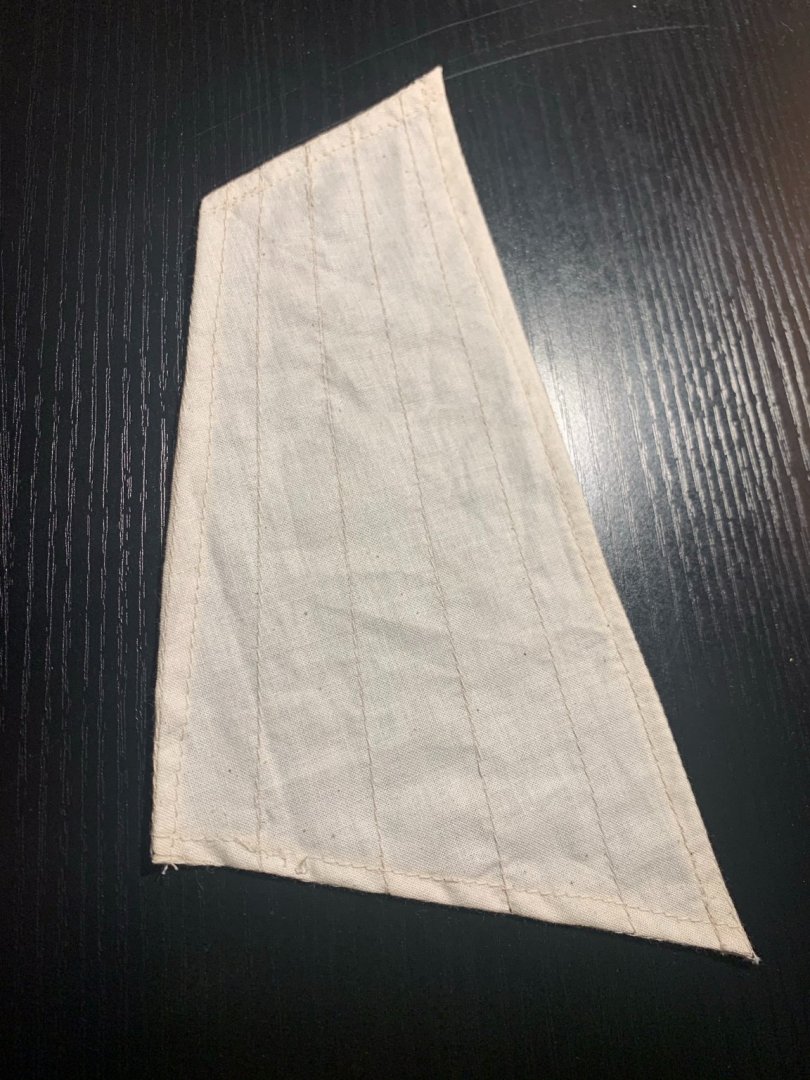
Here is the sail after letting dry overnight. It removed easily from the plywood:
r
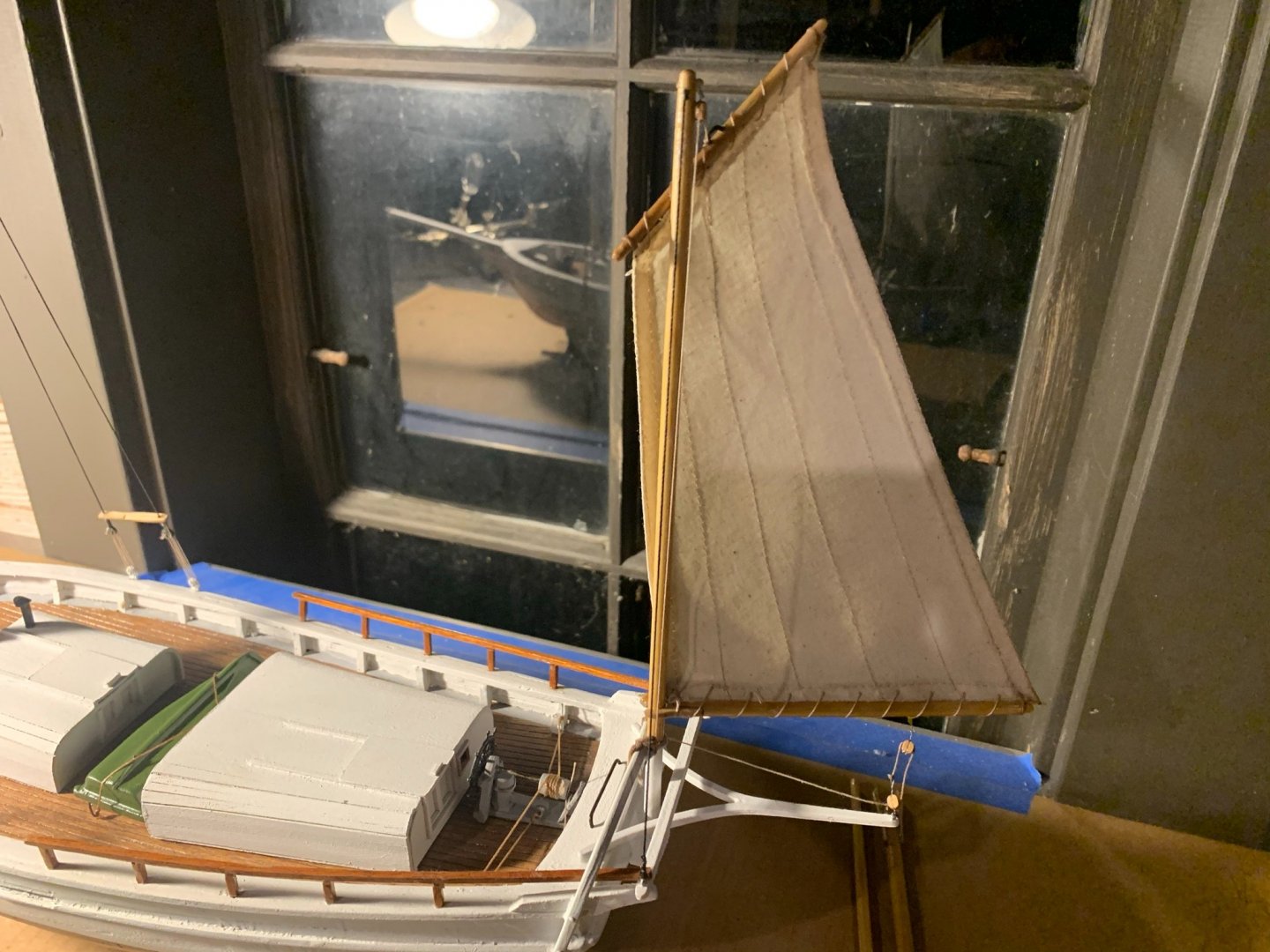
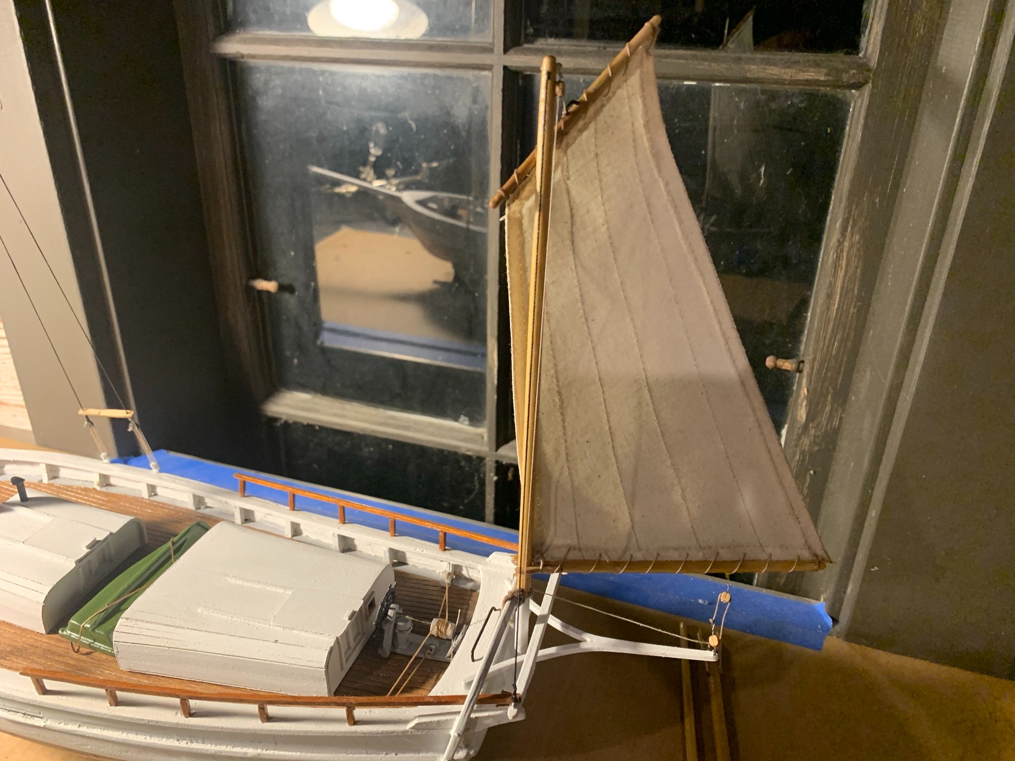
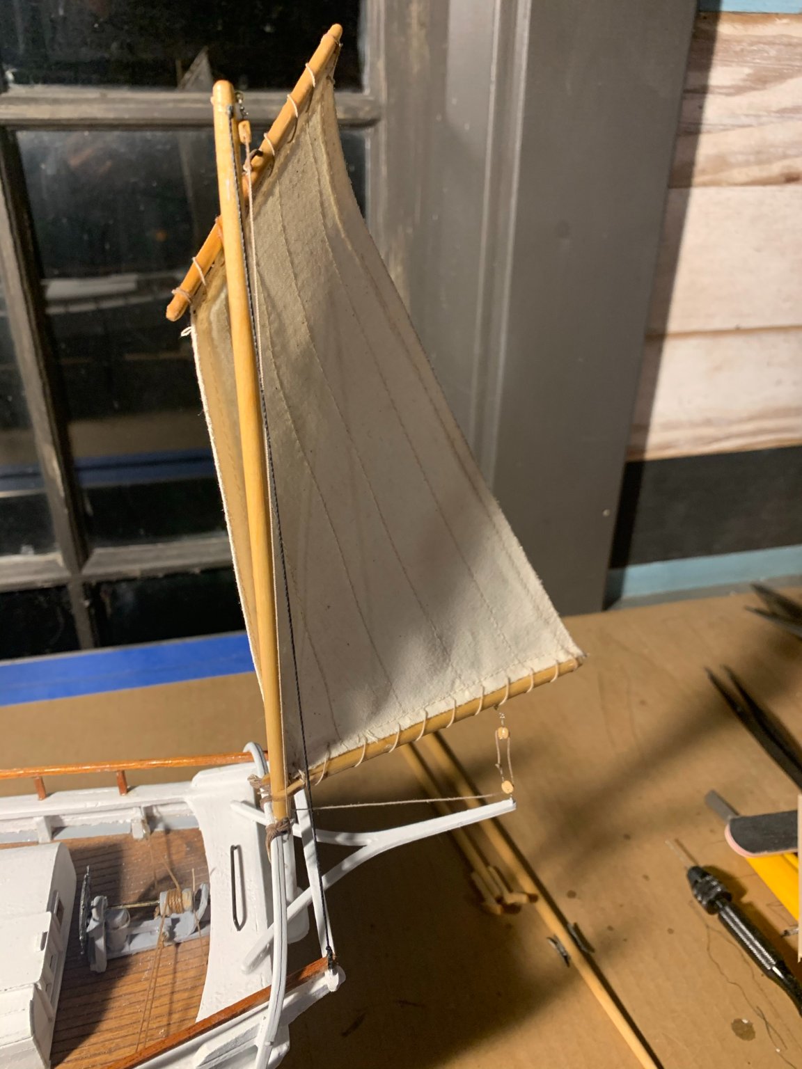
6) After removing from the form, proceeded to stitching the sail to the yard and boom. Rigged the sheet blocks and lines, hoisted the halyard and positioned the sail. Added a drop of glue where the yard touches the mast to help keep in position. Coiled some line around the pins at the base of the mast...

- lmagna, Duanelaker and ThirdCoast
-
 3
3
-
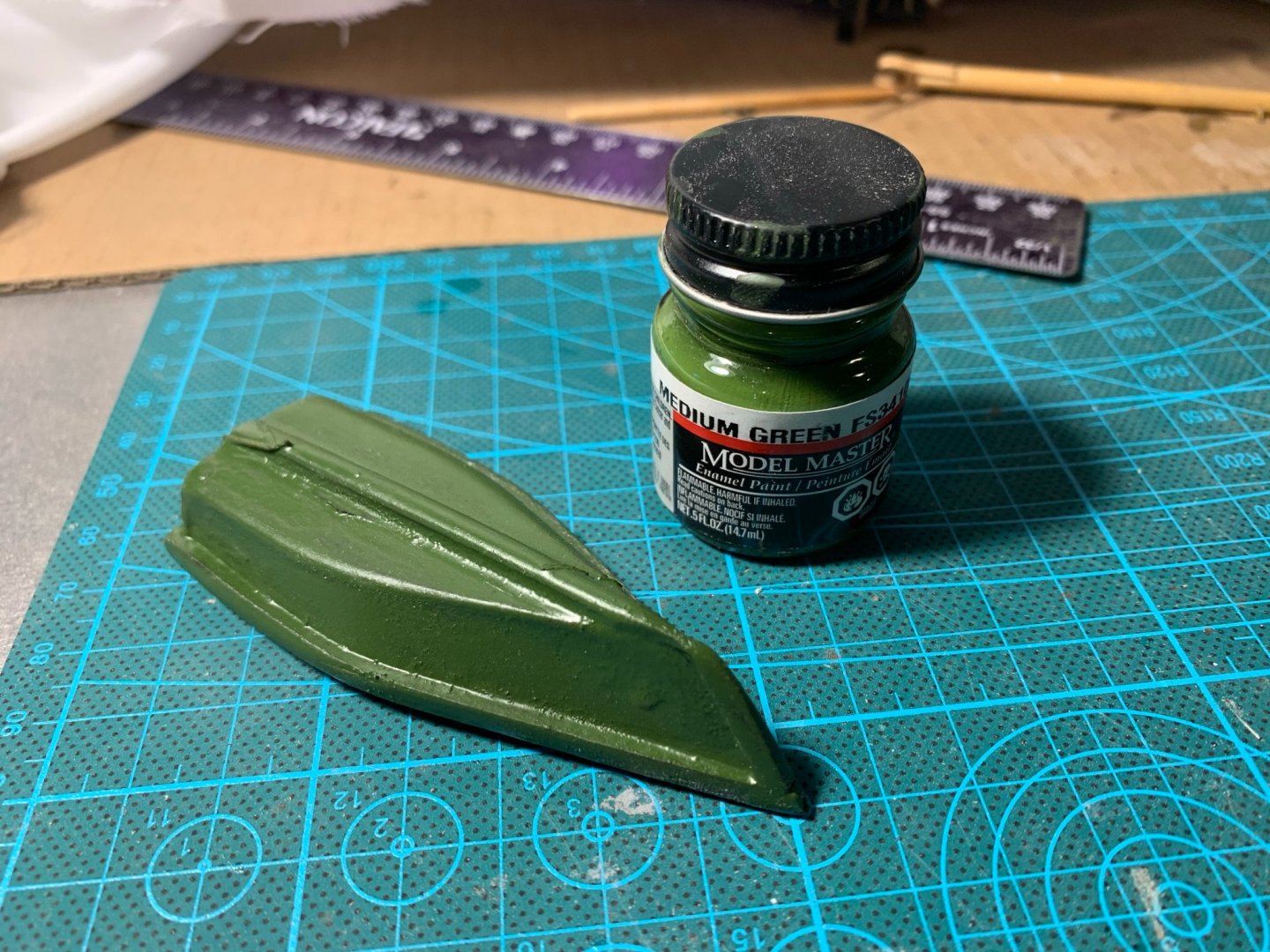
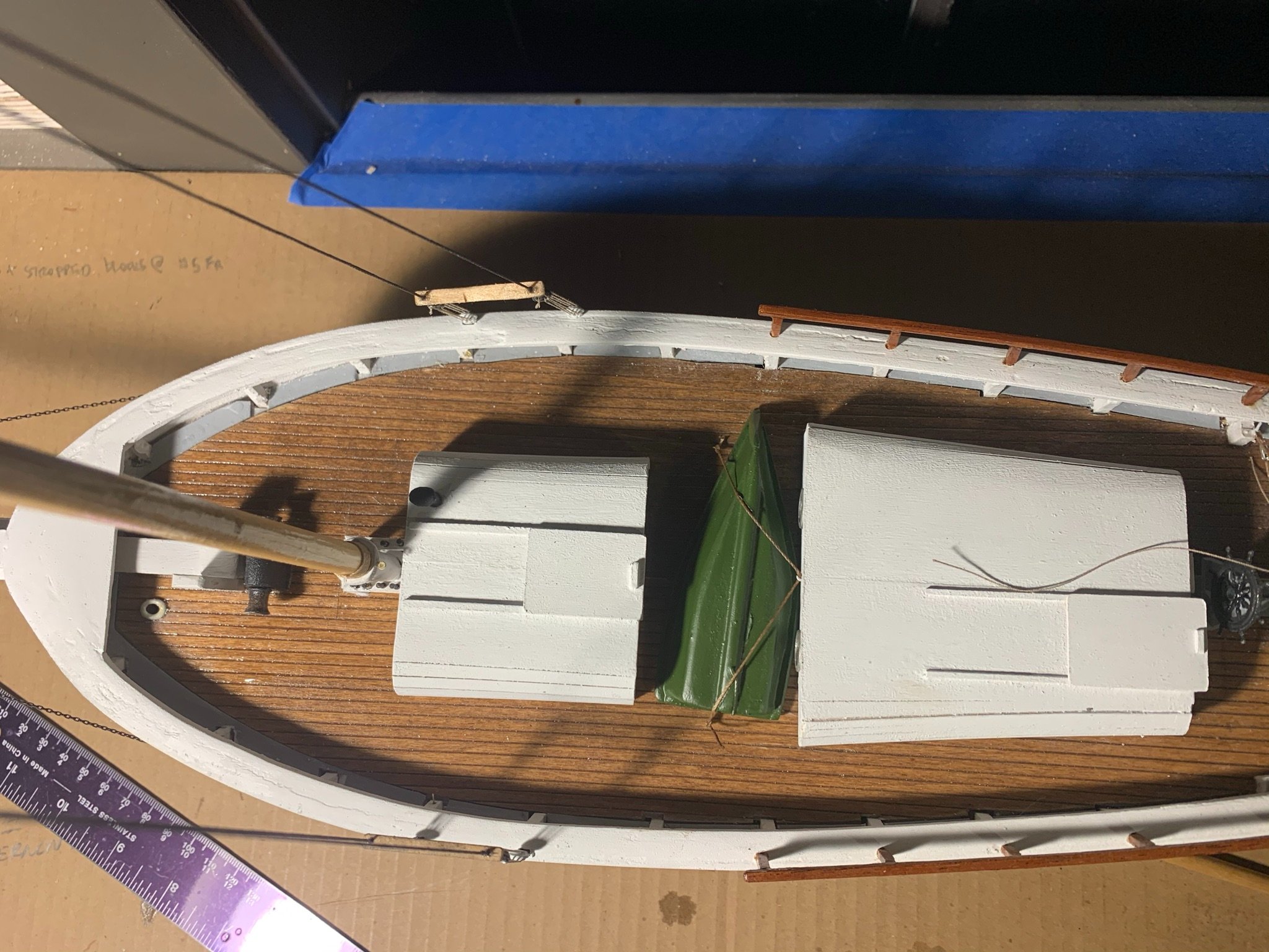
Ordered this Model Master "Medium Green" enamel for the skiff and repainted over the black.
Below is how it turned out. I think the green compliments well and isn't obnoxiously bright.

- lmagna and Keithbrad80
-
2
-
On 9/16/2020 at 6:31 AM, Tomculb said:
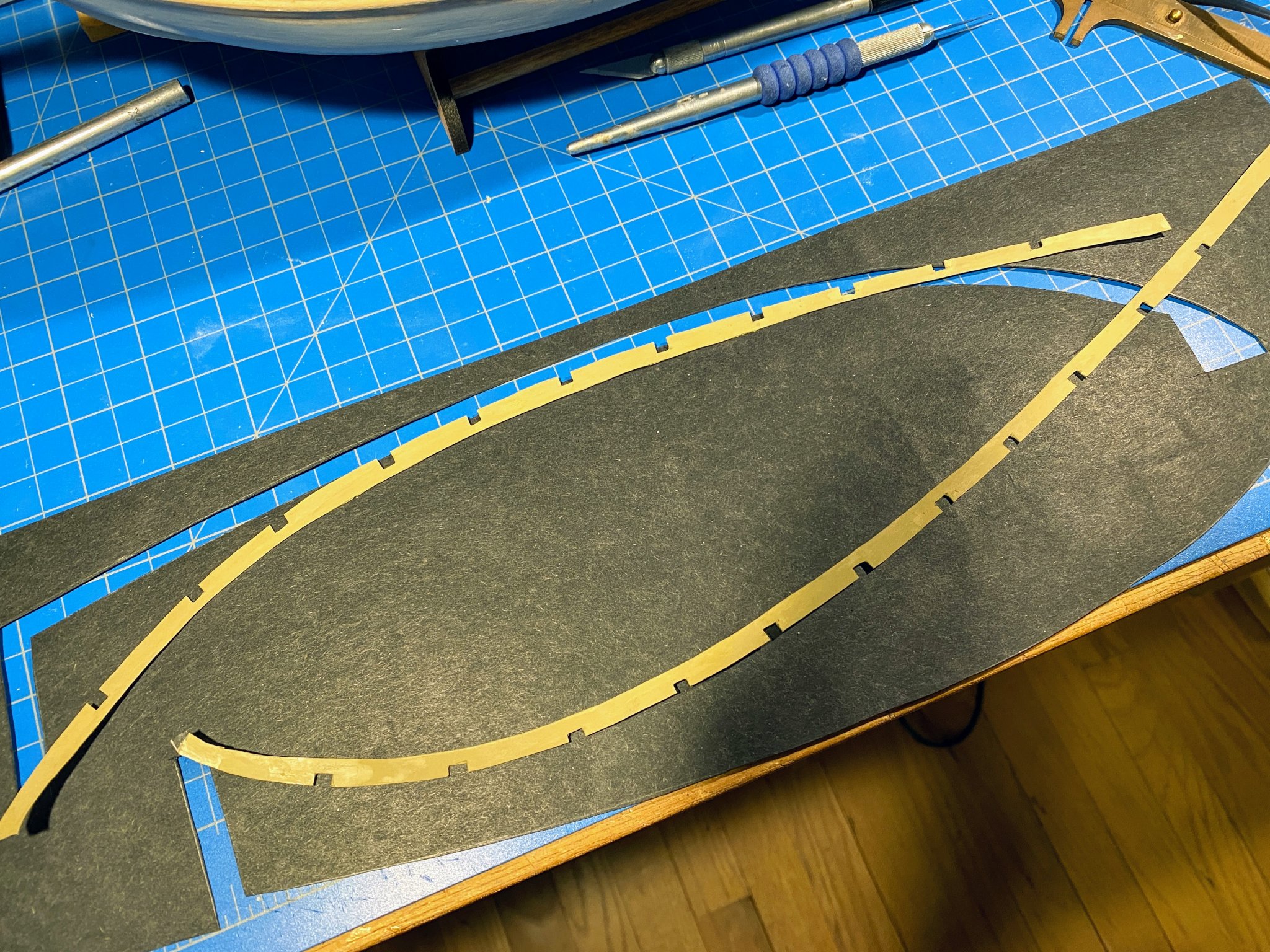
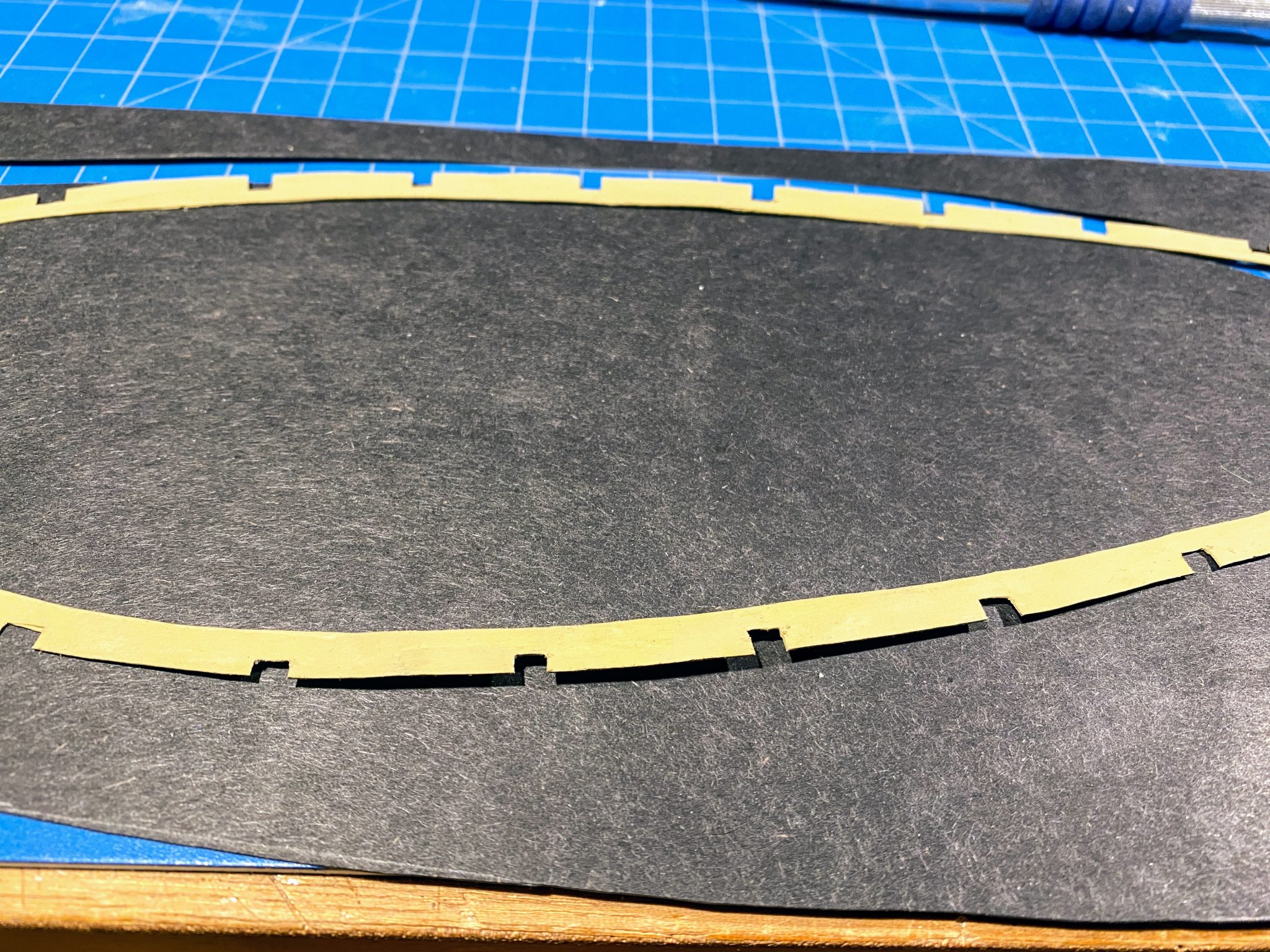
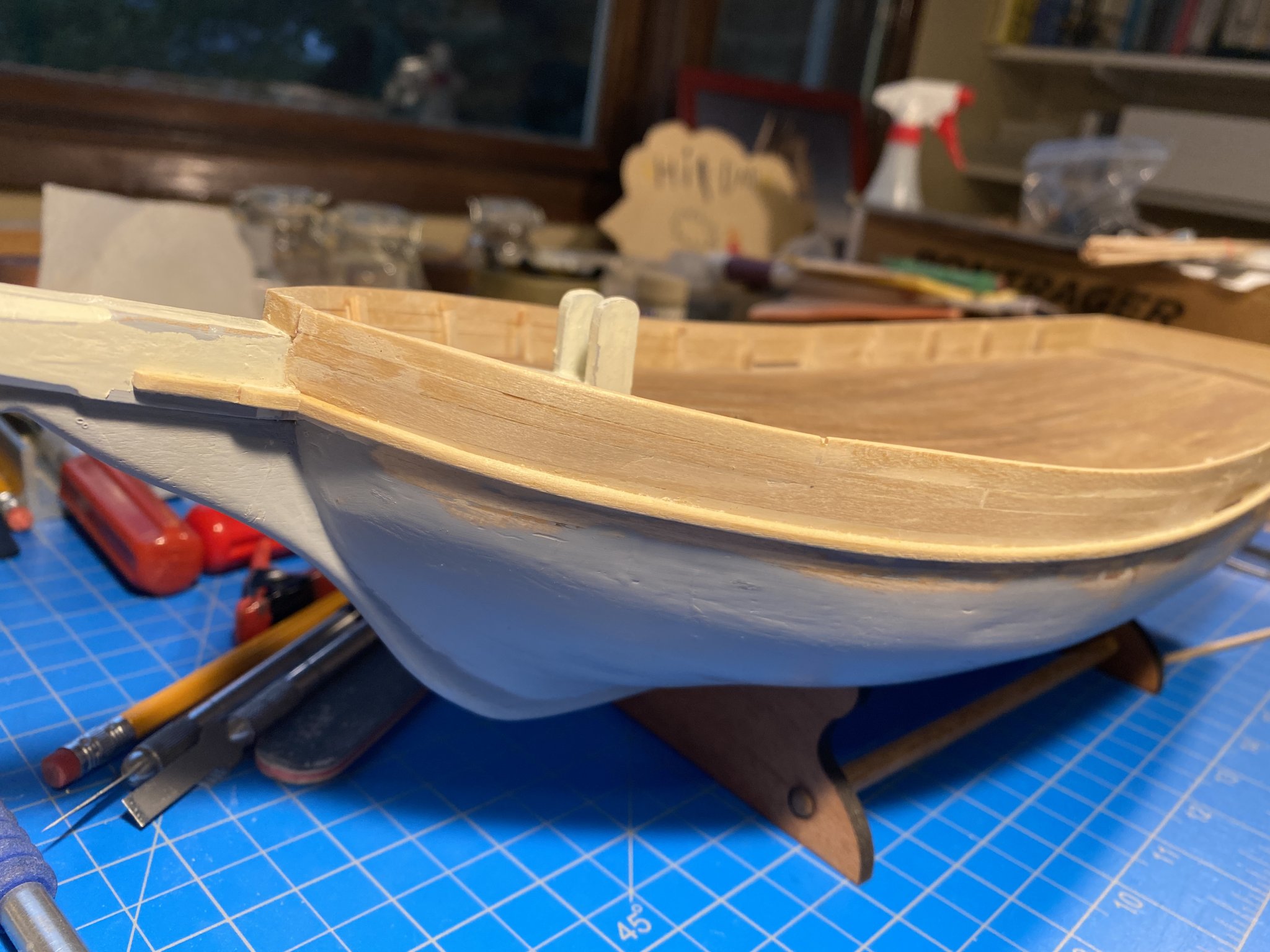
In my prior post I mentioned creating margin planks (or waterways) which would lie on top of the deck planking, not adjoining it. Basically I was too lazy to try to make the edge of the deck planking precisely meet the edge of the margin plank. In retrospect that may not have been a great decision, but it is what it is. The kit-supplied laser cut pieces would be too thick and too obviously lying on top of the deck. The instructions say they are to be painted along with the inside of the bulwarks (I’m wondering a bit why), and I felt they had to be thick enough to absorb the paint without wrinkling. After looking at a few alternatives, I settled on some construction paper (that happened to be black). I cut them out with an X-acto knife, then used some small sharp scissors (usually used for cutting rigging line) to cut the insets for the stanchions. Then they were painted the same Buff color I used on the cabin trim. They will be installed later.


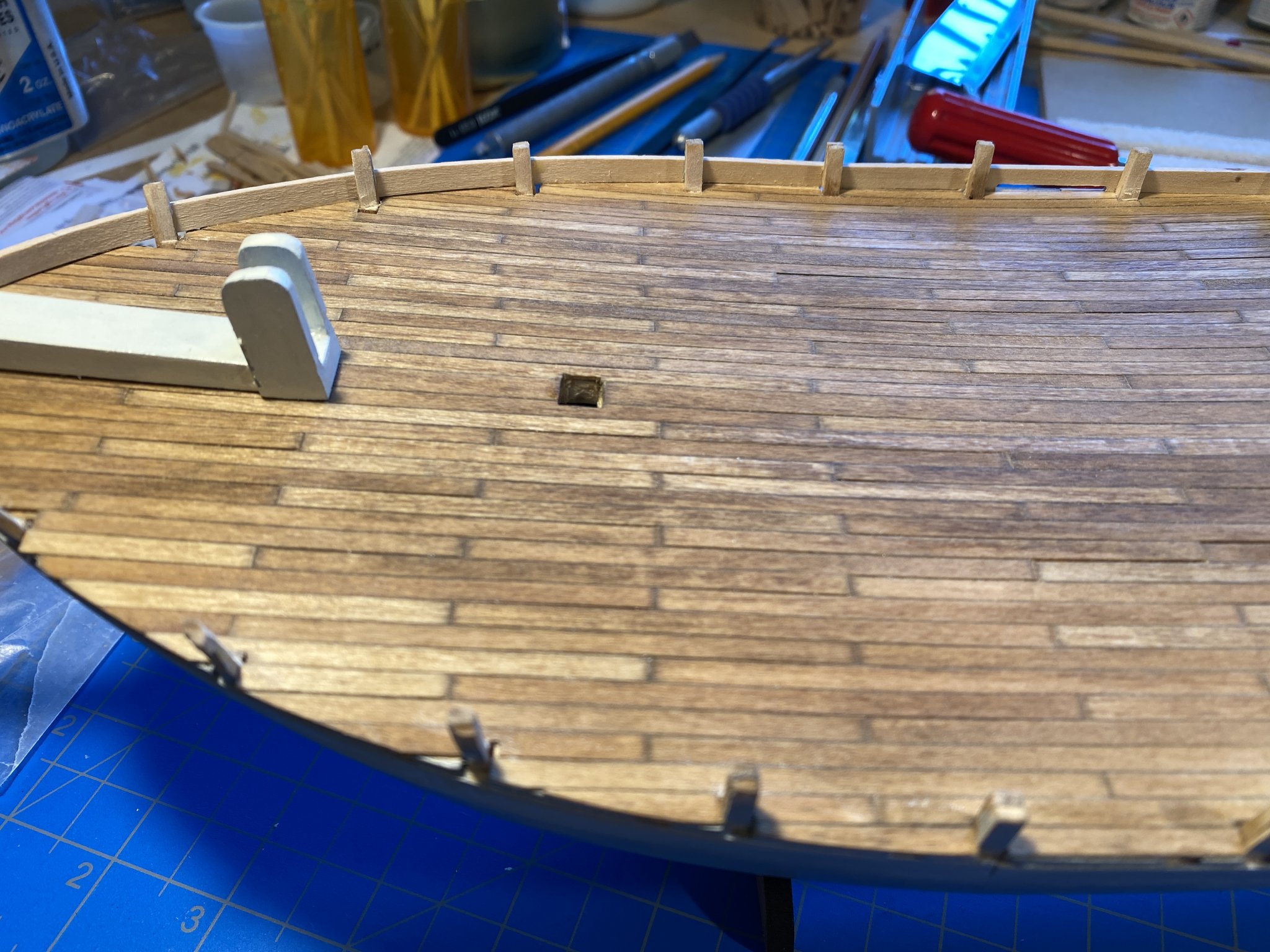
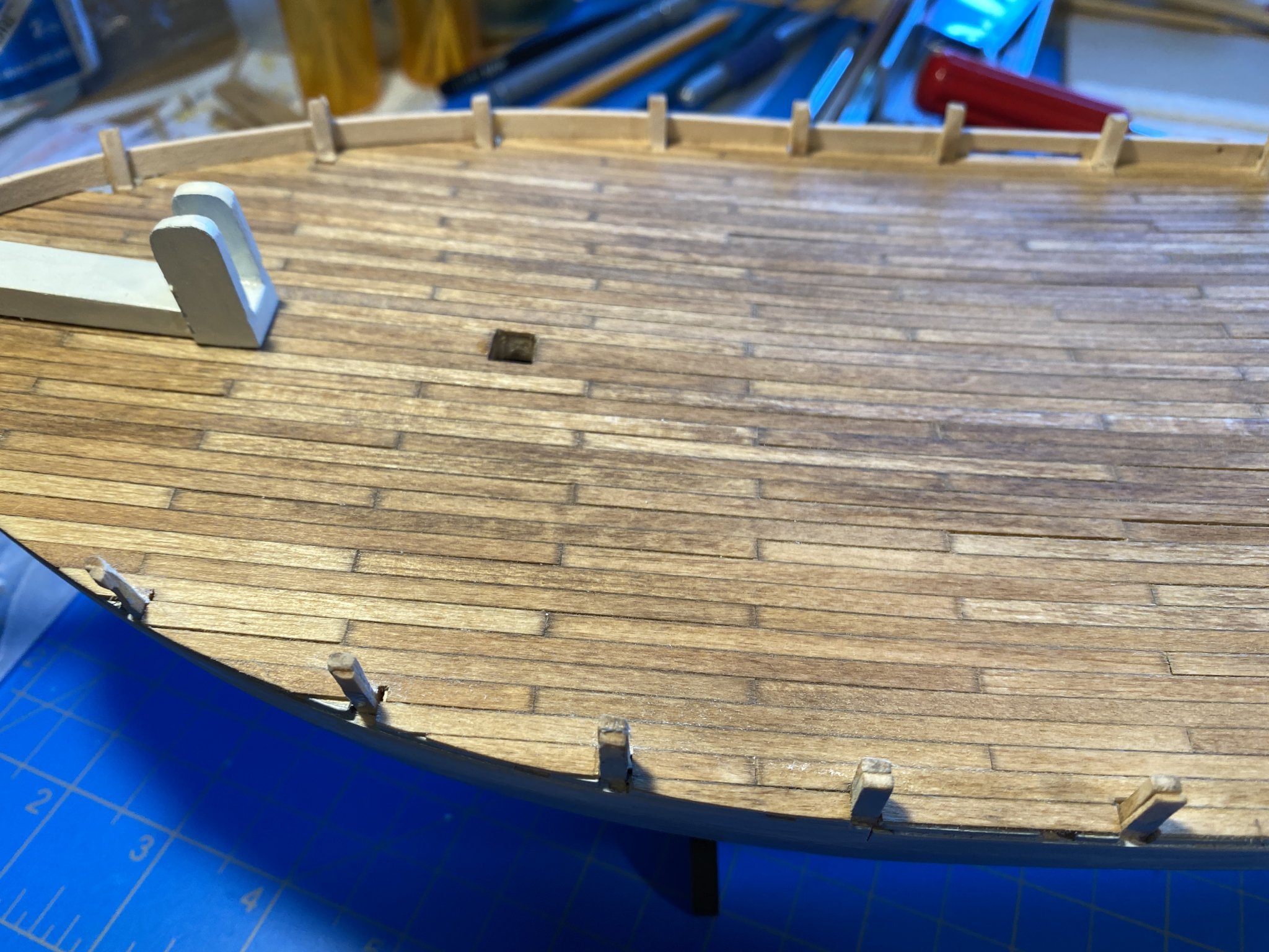
Next was bevelling the stanchions to accept the bulwarks planking, which involved a bit more work than I anticipated. A lot of wood was removed in some places, shims added in others, etc. No pictures of this task.
I also realized that if the bulwarks are to be a consistent ½ inch above the shear line as shown on the plans, then most of the stanchions were a little short, and they certainly weren’t consistent in height. That I would deal with another day.
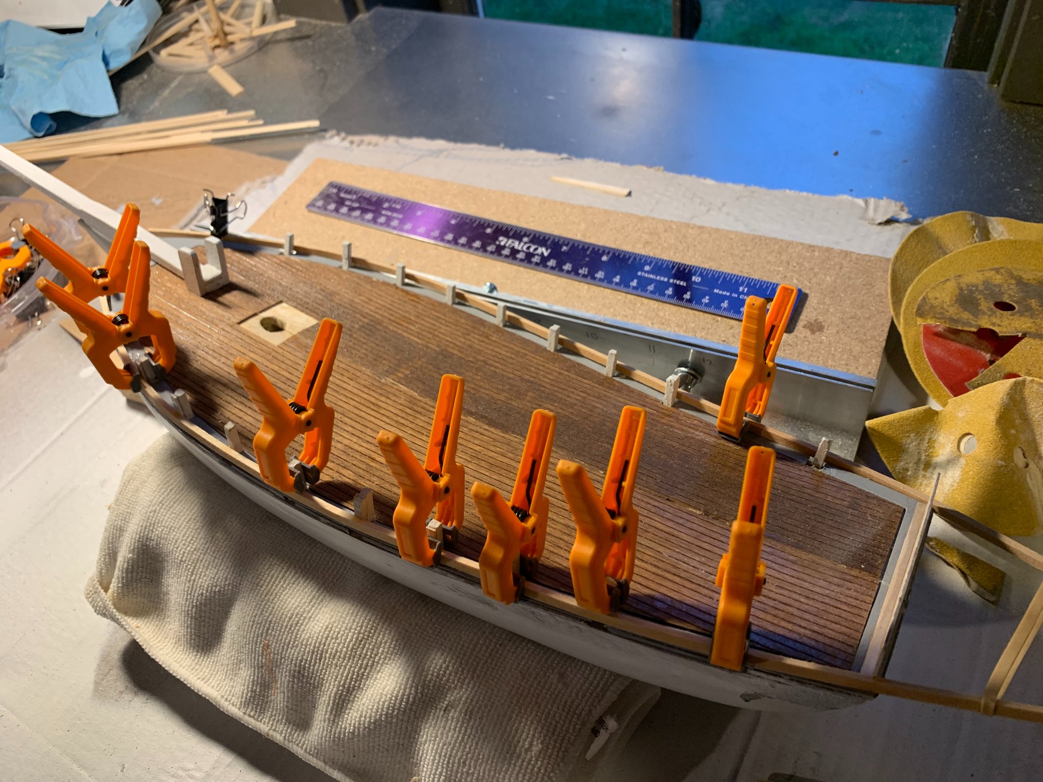
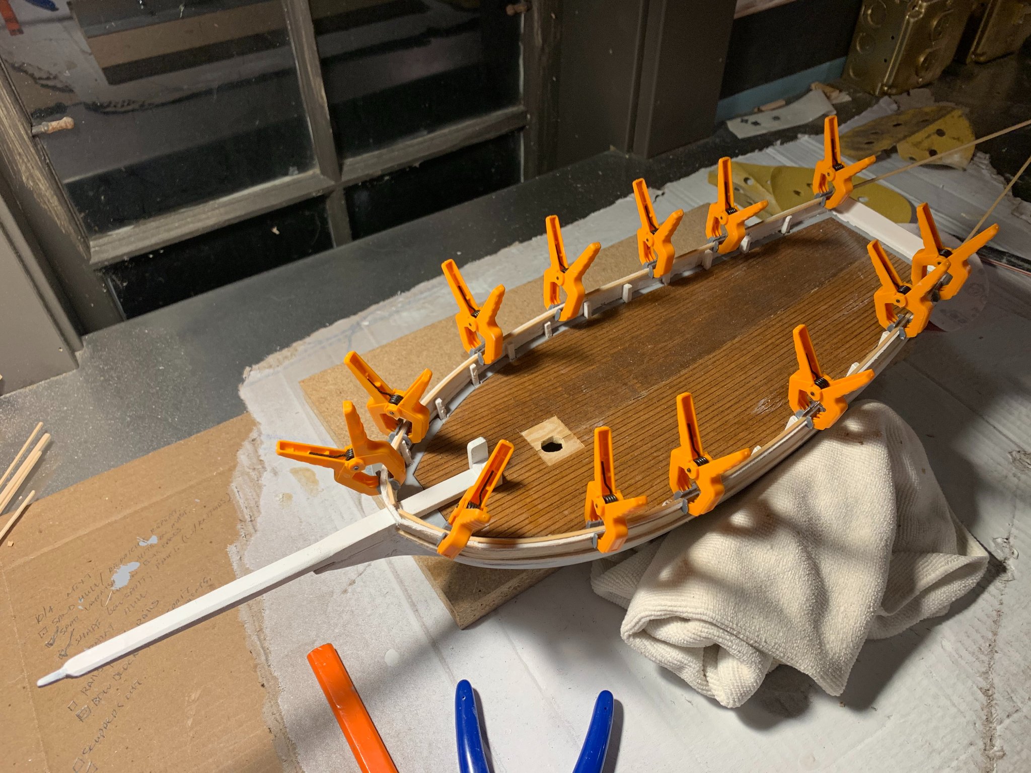
Nothing very exciting about planking the bulwarks. As I started to do midway through planking the rest of the hull, I used Chuck Passaro’s recommended method of wetting but not soaking the planks, then using an iron to bend the wood around the stanchions. The iron I’ve been using is left over from applying Monocoat to R/C gliders I built another lifetime ago.


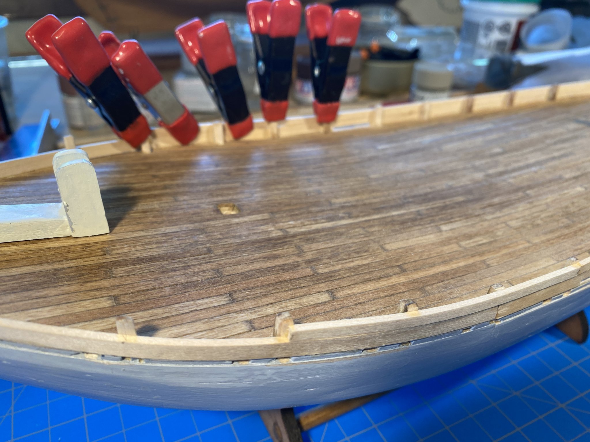
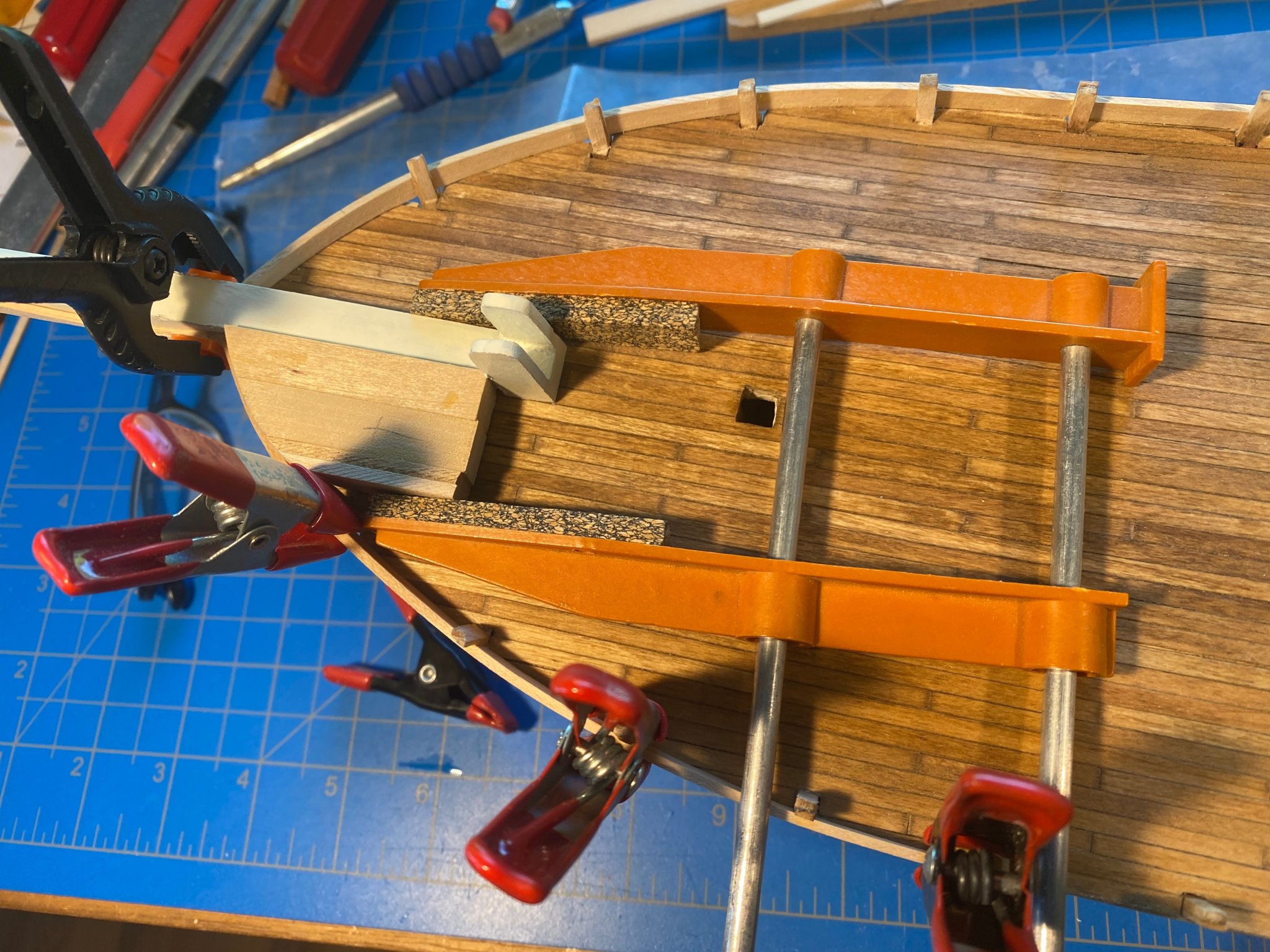
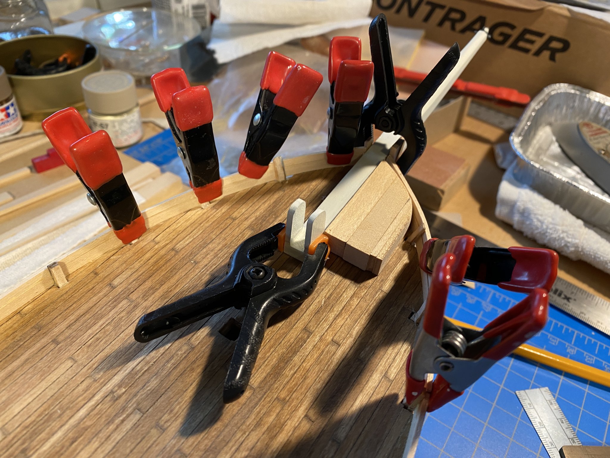
At the bow there isn’t anything to bend the planks around, so I built a block to serve that purpose. Holding everything in place sometimes required some creative clamping.


I made the transom bulwarks by first gluing the first plank onto the hull and deck, then adding the stanchions at each corner, then adding the remaining planks.
Along the way I started building the steering apparatus, none of which has been glued together or painted yet. Also below, transom planking further along than above.

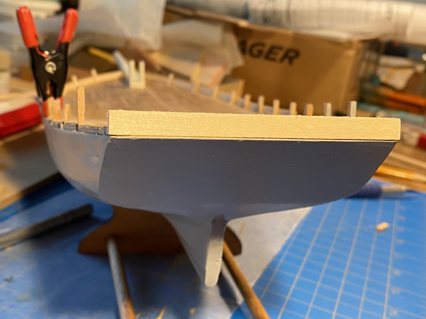
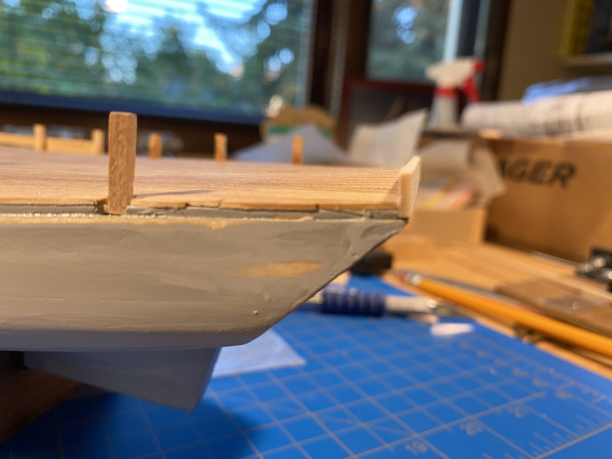
What followed of course was a great deal of wood filler and sanding. Here are a few "before" photos; "after" photos are further below.


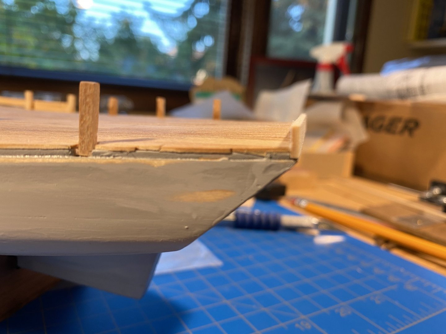
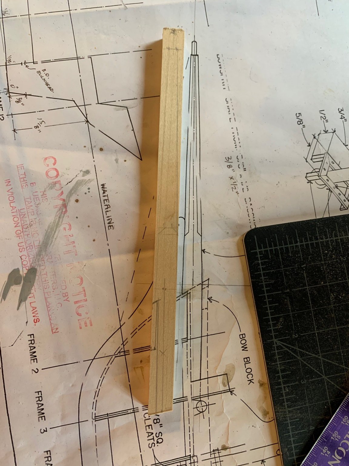
Next came the rubrails. The plans show them to be 1/16th of an inch from top to bottom, and the inventory shows 1/16 x 3/32 strips to build them with. I took a couple of those strips, rounded the sharp corners, and glued the 1/16th edge to the hull. I also used a single strip for each one, wanting to avoid any sharp bends where two strips join. The rubrails run part way out onto the sides of the bowsprit, and I made those parts with two short 1/16 x 3/32 strips glued side by side. All in all the process went pretty well.

At this point I made some decisions about the caprails. The deck plan shows them to be 1/4 inch wide, which looks about right. But a cross section of the hull shows them to be quite a bit wider -- 3/32 strip outside the bulwark, 3/32 width of the bulwark plank, 1/8 stanchion, and another 3/32 strip inside the stanchions, for a total of 13/32 (or easier for my mind to grasp, a gnats eye wider than 3/8). That just seems too wide. As mentioned earlier, I used 1/16 for planking, and the part of the rubrail outside the planking could also be 1/16. Most of the stanchions were thinner (after beveling) than the 1/8 square they started with, and a 3/32 stanchion seems like a good width. And the inner plank might even be 1/32 (left over from planking the deck). Moving outward in, that’s 2/32 + 2/32 + 3/32 + 1/32, for a total of 8/32, or 1/4 as shown on the deck plan. I think that will look better.
Having made that decision, I added shims to some stanchions, shaved some stanchions, and added tiny caps to most so that they are all a consistent thickness and height. The photos below were taken when I was close to finished with that task.
As I write this I'm ready to start installing the cap rails. But first I think I will glue the waterways in place, then paint the inside of the bulwarks.

Tom, looking at your post again in more detail, I'm amazed at how smooth your hull looks. What kind of wood filler have you found works best for you? And I assume there were several sessions of filler/sanding? Good job, it really is coming together!
-
Some odds and ends from Days 16 and 17 of the model build:
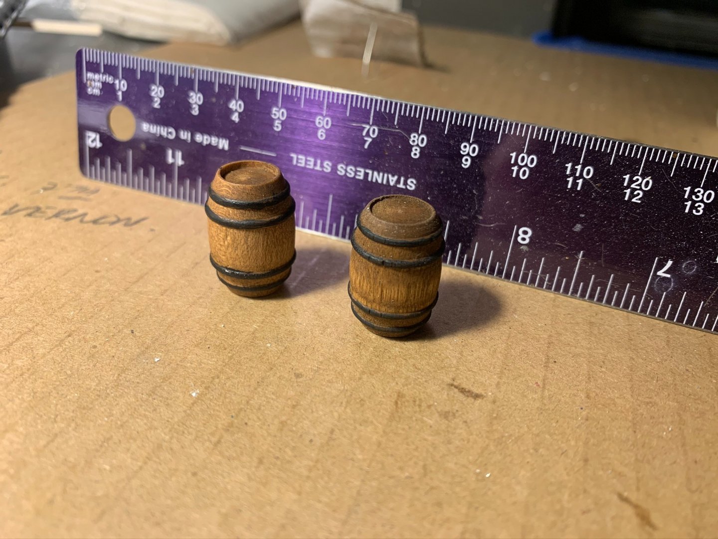
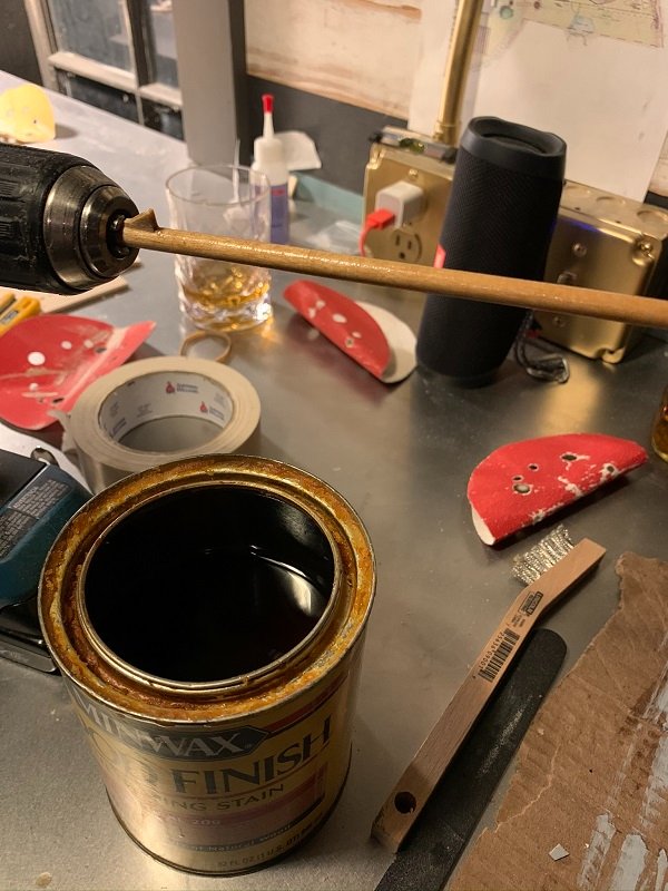
1) Took some time to work on the barrels: These were first coated with some Early American stain, and then finished off by painting the barrel straps black.
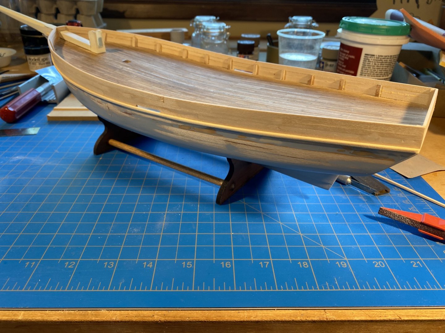
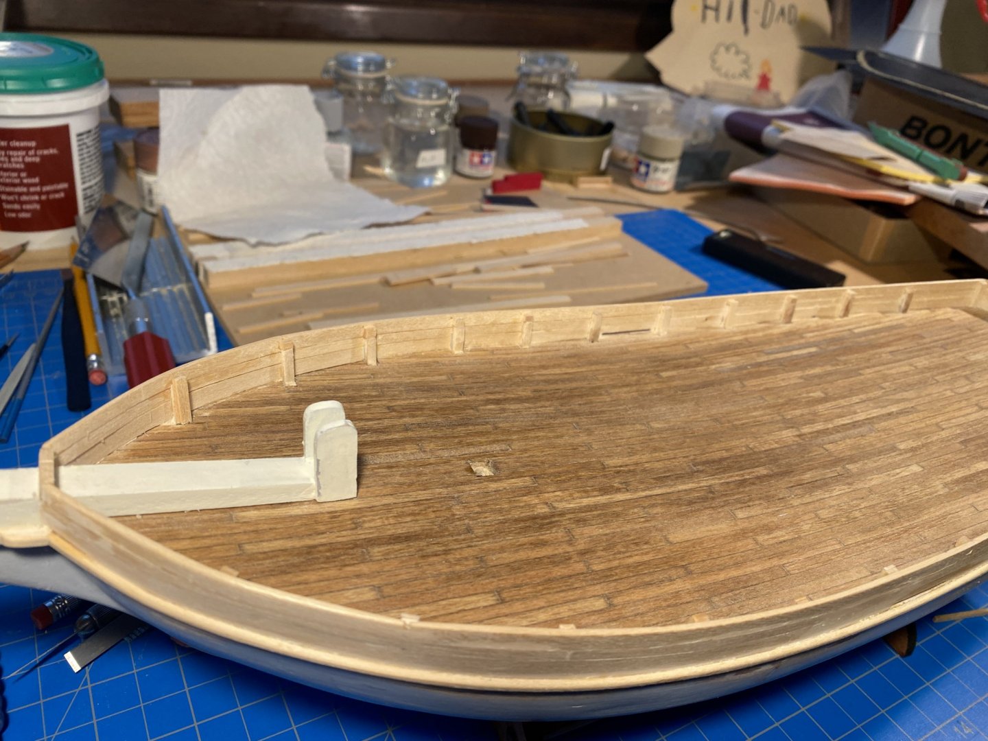
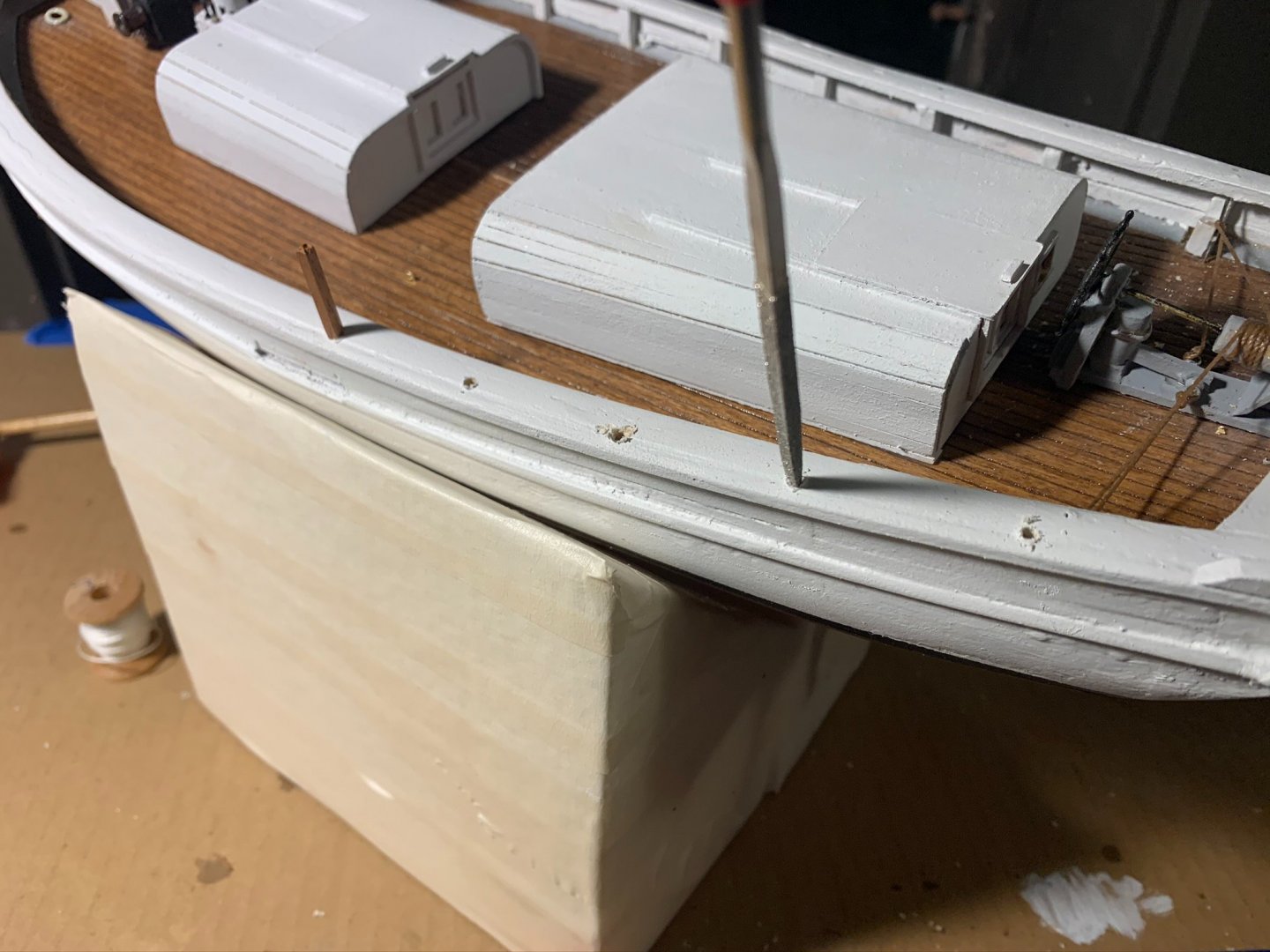
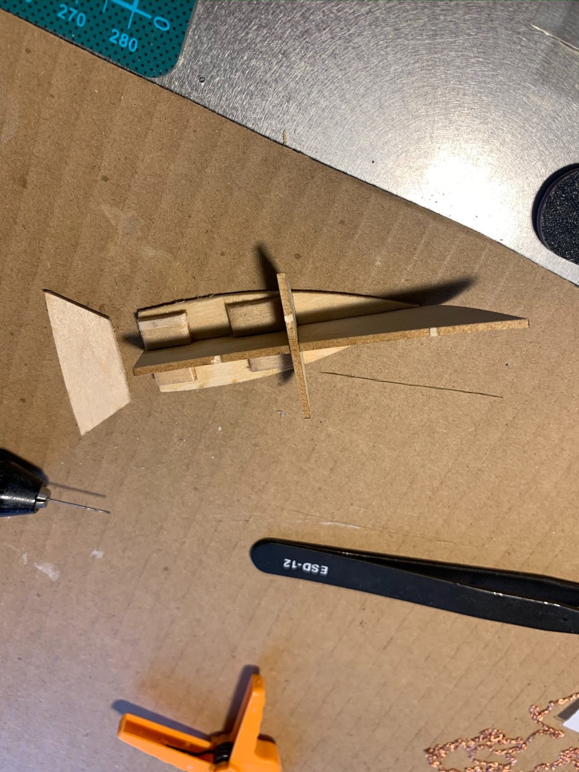
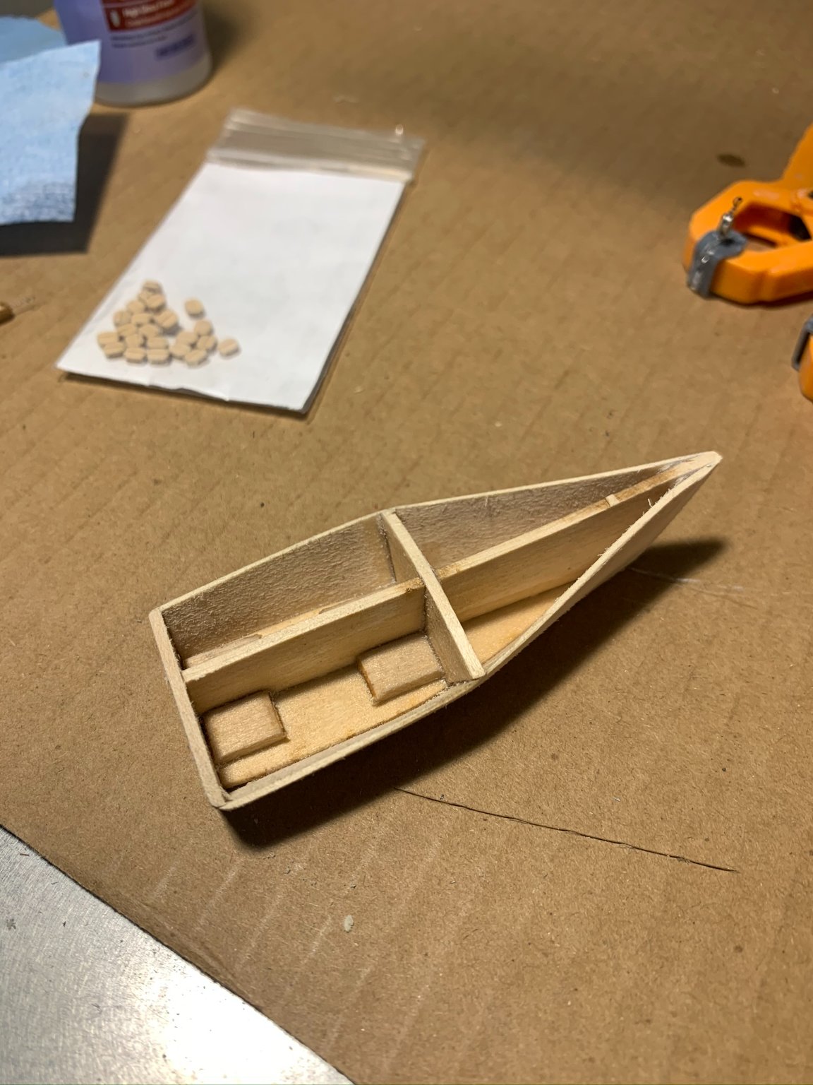
2) I have been excited about starting the dinghy since I opened the kit; so no better time to start than now!
At about this time, I compared the dinghy size to what is drawn on the deck plan, and realized it was a bit larger in the modeled form. It still fits in between the two cabins, but the barrels do not fit along with the dinghy as drawn - there's just not enough room. I believe all of this is stemming from the steering gear being a little forward from where it should have been placed.

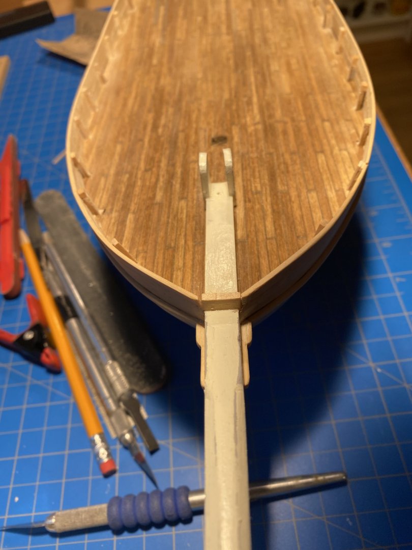
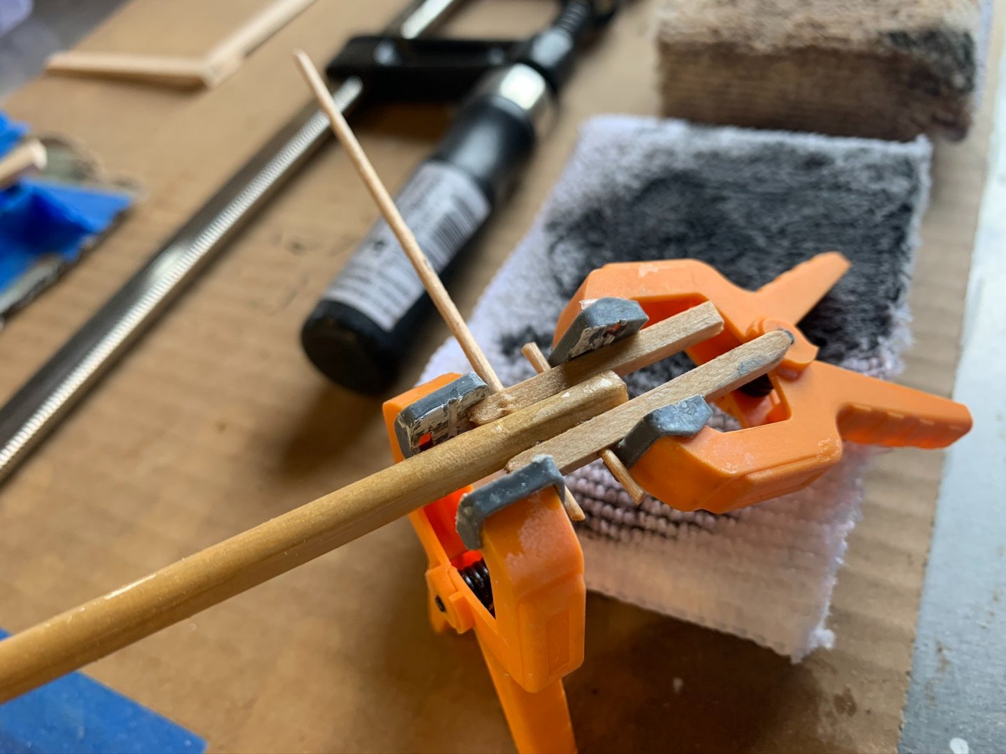
I placed some rails, and a strip along the center for the keel:
I only had some flat black rattle primer, so that's what I used (for now).
The reference from "Sailing Alone Around the World" that gives indication of the dinghy color is this:
"The Spray being in the stream, we boarded her from the beach abreast, in the little razeed Gloucester dory, which had been painted a smart green. Our combined weight loaded it gunwale to the water, and I was obliged to steer with great care to avoid swamping. The adventure pleased Mrs. Stevenson greatly, and as we paddled along she sang, "They went to sea in a pea-green boat."
So, I will search for a period-appropriate dark green to paint over the black later...

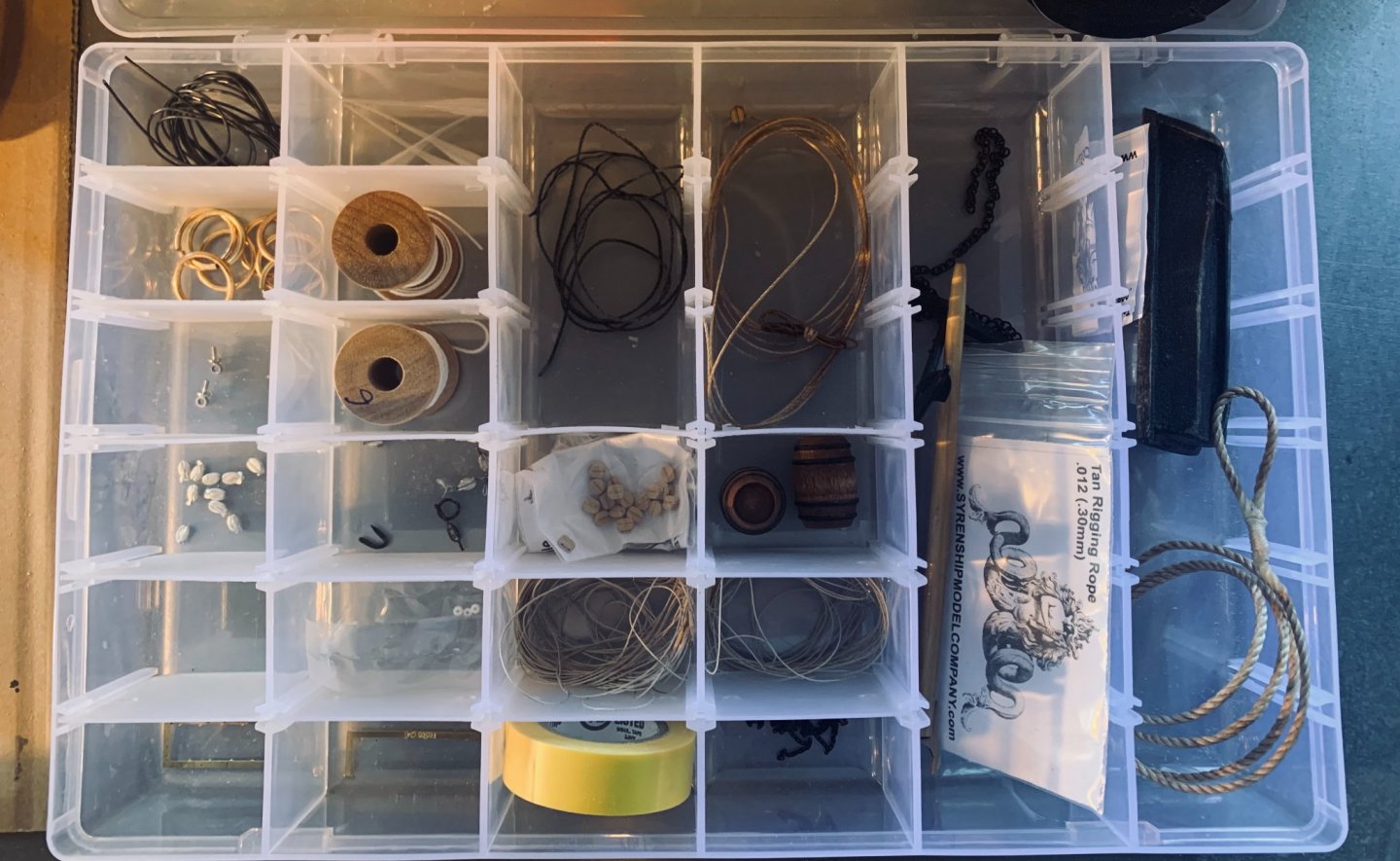
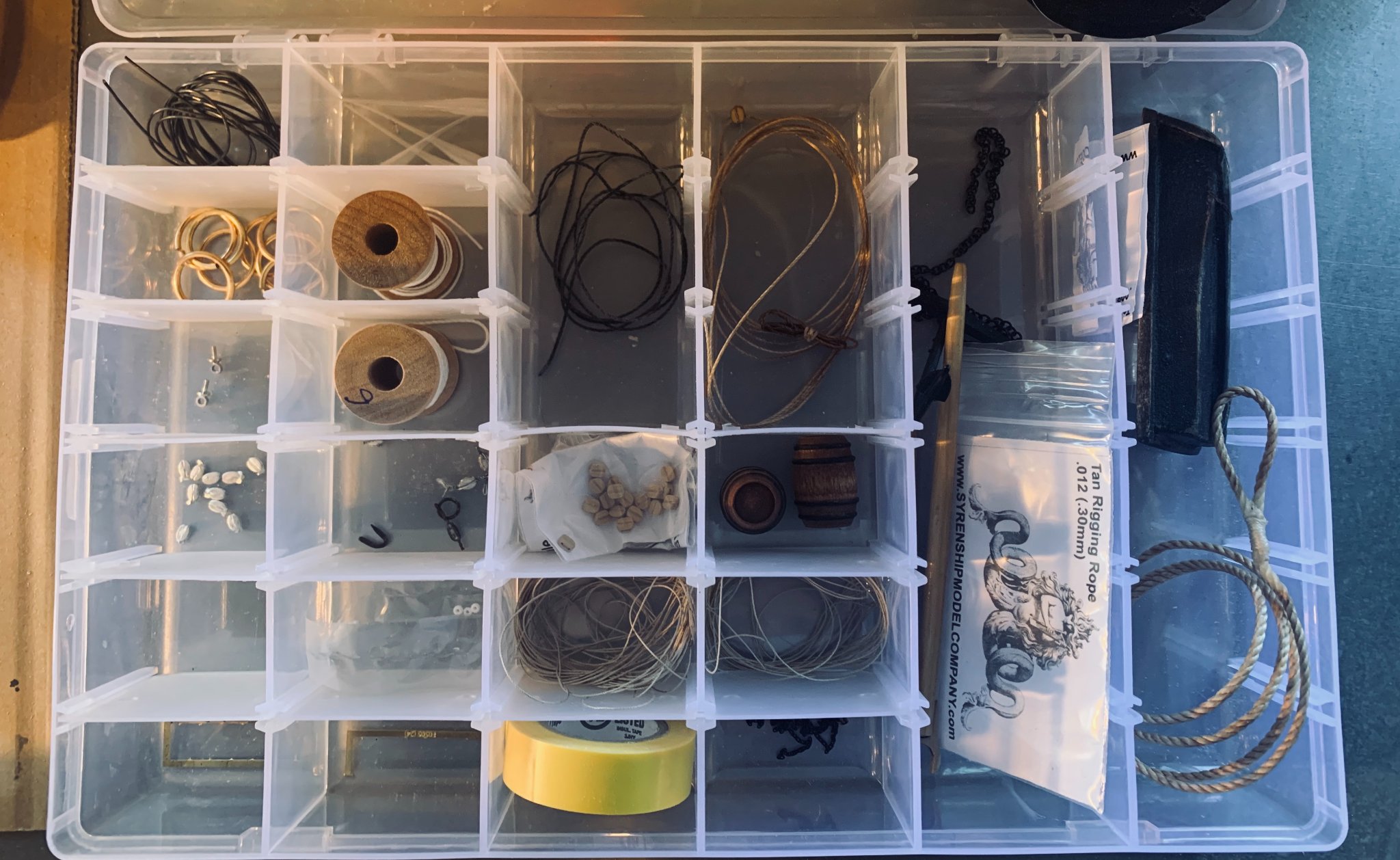
3. Albeit somewhat late in the process, I wanted to get organized with my fittings , so I finally acquired a little plastic case to keep everything dust-free and organized.
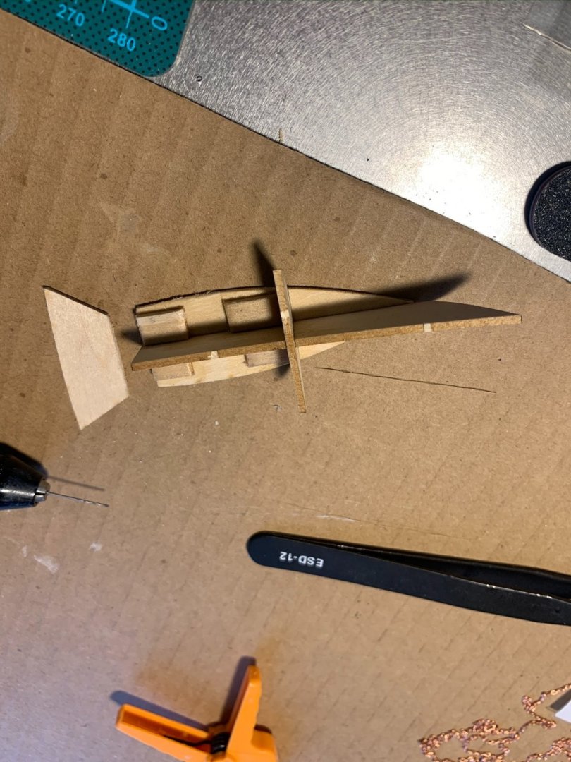
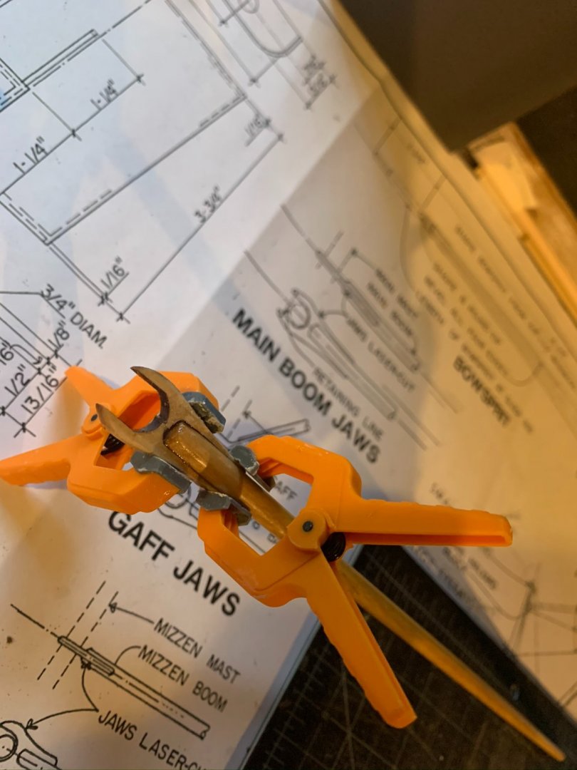
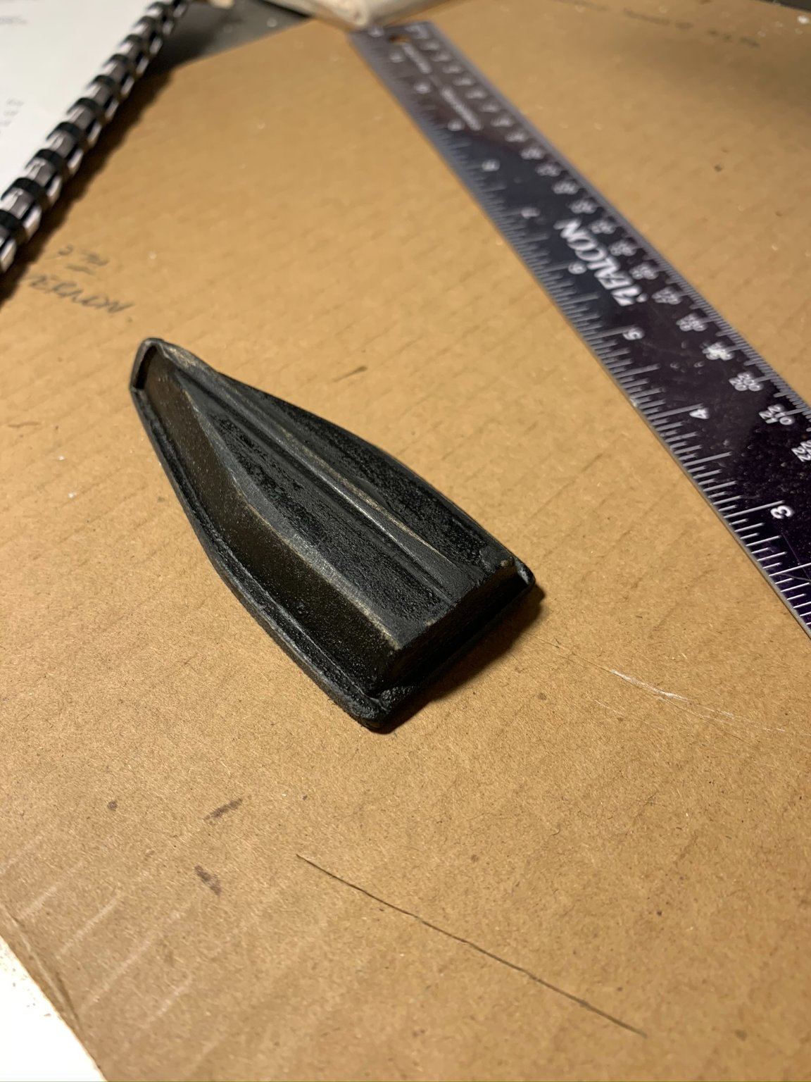
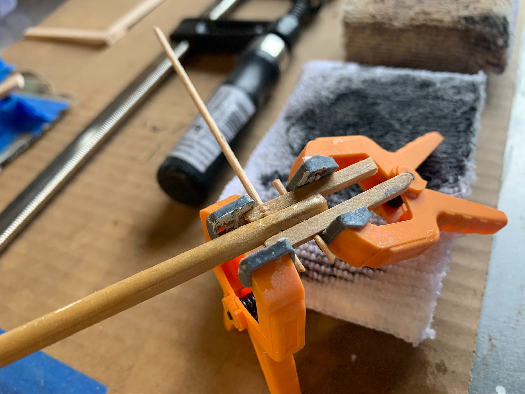
4) Lastly, I am still working through a solution to making the gaff jaws. Not sure what the next steps will look like here, but I am hoping they will look a little more realistic as I continue to work on them.
All for now-
-
14 hours ago, MrBlueJacket said:
Just curious - how many hours a day are working on this model?
Nic
Hi Nic,
Every day is a bit different: I usually spend at least 3-5 hours working when I sit down for a session, but there have been some 7-8 hour days as well as one or two "all-nighters." I would guess I have about 80+ hours into the model by now. I am really enjoying this model - starting to think about what may be the next one!
Good job on putting together a solid kit Nic!
- dsmith65, Keithbrad80 and Duanelaker
-
3
-
Following up with the remainder to my previous post...
Spent the latter part of my 15th model build day working on the mahogany rails.
15-B:
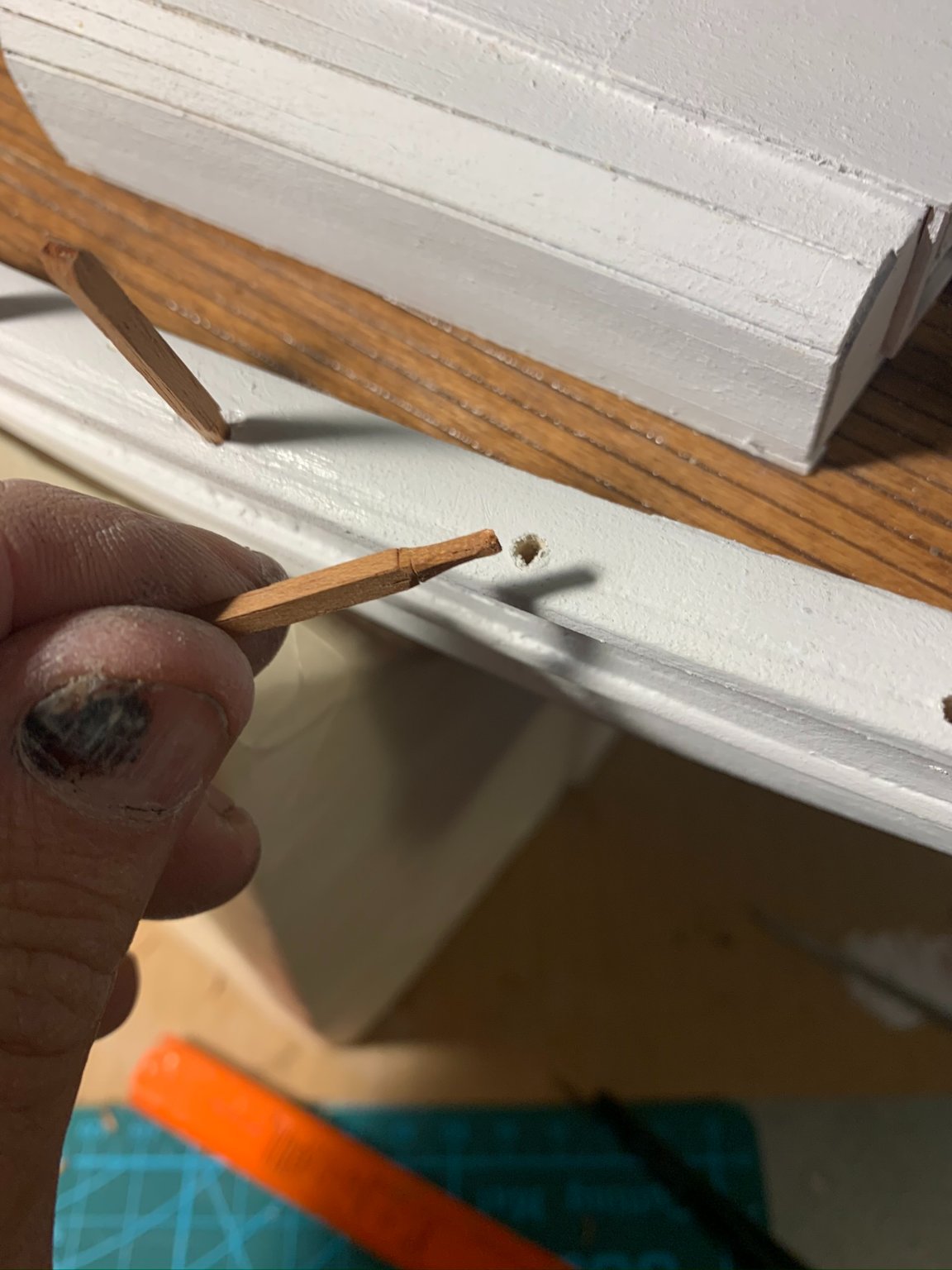
1) Laid out for the spacings, and drilled a small 1/16" pilot hole in the cap rail. Finished hole with a file, and cut rounded ends on 10 mahogany stanchions. (I cut them long so that I could place a long continuous piece against all rails to strike a line and cut to height).
Close up view of the rounded ends:

2) Once I had test fitted all of the stanchions in their respective places, I took them all out to stain them with a coat of gloss.

3) Glued them in place and measured out the height of each stanchion by placing a long mahogany piece along the edge, and then marked the tops.
Below: I had a couple stanchions that depending on if my drill hole was perfectly perpendicular tended to "lean" one way or another. This was my attempt to straighten some out in the gluing process...
Same step, different view:

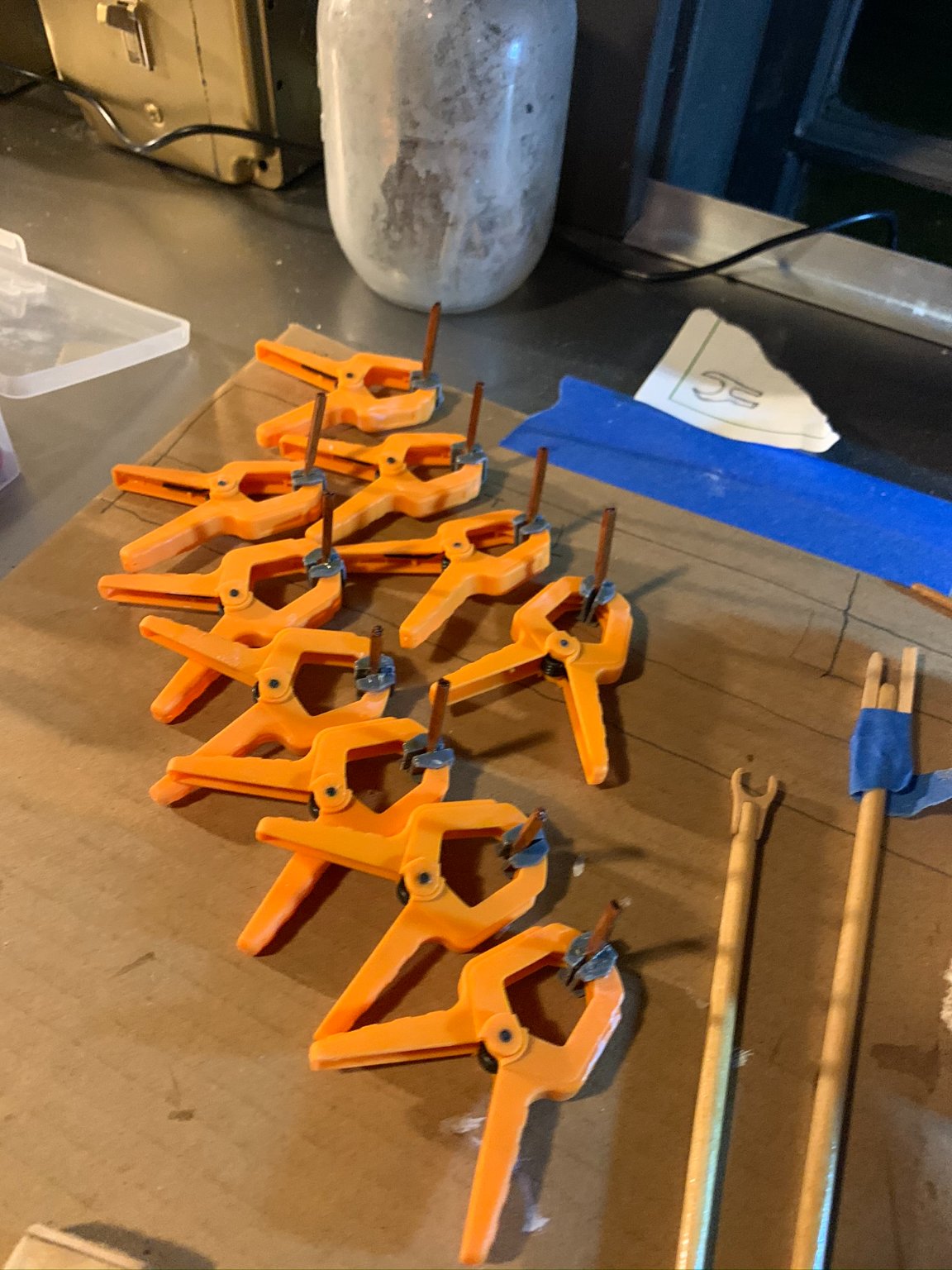
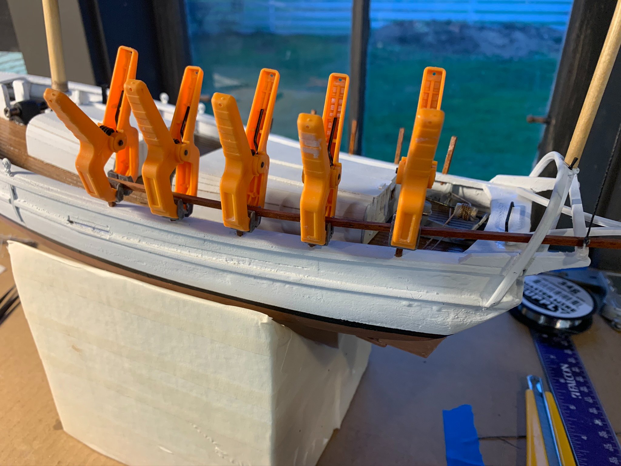
4) After sufficient time gluing, I set the final top rail in place and clamped.
NOTE: In this process unfortunately, I had some CA glue run down the side of some stanchions...also some of these clamps had actually glued themselves to the mahogany. Boo! I broke some glued connections when unclamping and had to re-glue where needed. Also not shown is some significant post-sanding that needed be done to clean up some "over-glued" areas that ran. The result of this is that the efforts of pre-staining the stanchions was wasted effort. Oh well...

5) Below, (and after some time fixing some connections and messy glue), is the final product, sanded. Next will be a coat of the "gloss" again, and will call this step done.
- Tomculb, Ryland Craze, lmagna and 2 others
-
5
-
-
On 10/28/2020 at 7:48 AM, Friday Dog said:
Josh - Nice detail work. Is the blacking solution you used primarily for modeling, or a more general use product?
Great job, so far.
Thanks Friday Dog. The blackening solution was something I had in the shop already for some metal blackening projects but found it worked well on the model work. The pieces only need several seconds in the bath to achieve a nice patina.
-
Day #15-A
In preparation for rigging blocks and lines, I took some inventory of what was included in the kit, and decided to purchase some additional materials. I found the thinner of the thread included with the kit would serve well for standing rigging (dipped in some ebony stain to mimic a tarred look). The larger thread included, I don't think I will use on this kit.
This post will be the first of two documenting Day 15 of my "Spray" build, this one focusing on fittings.
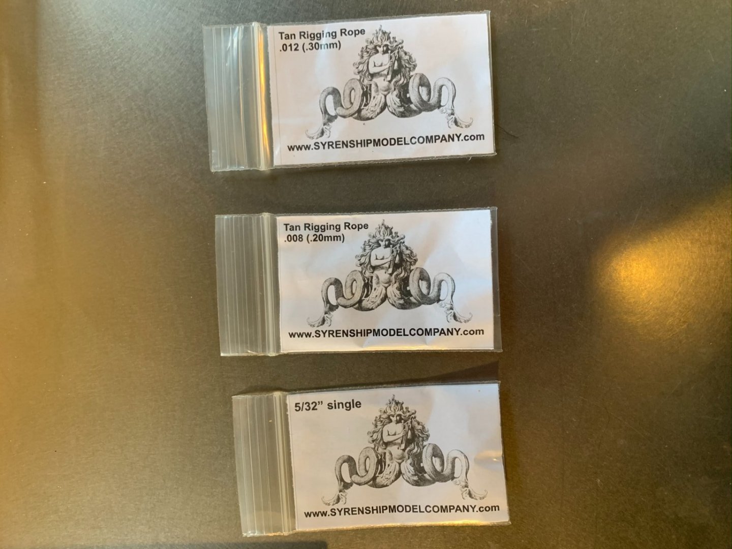
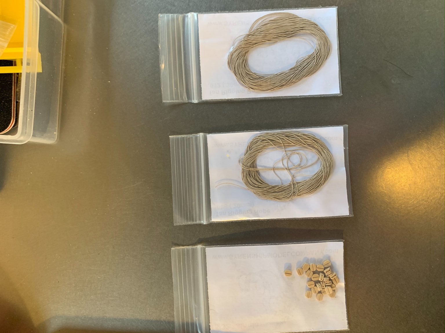
For halyards and sheets, I purchased some .30mm tan thread from Syren Ship Model company, along with some .2mm for seizing. Below are the pictures of the packages and reverse, the corresponding picture of what was included.

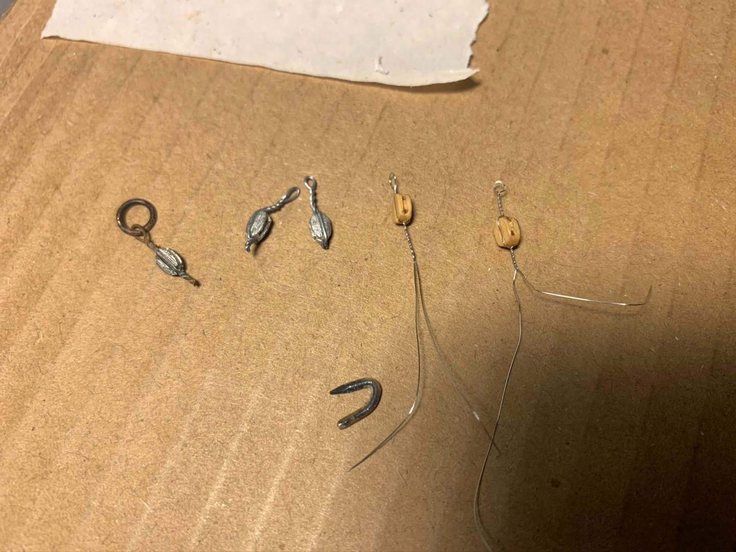
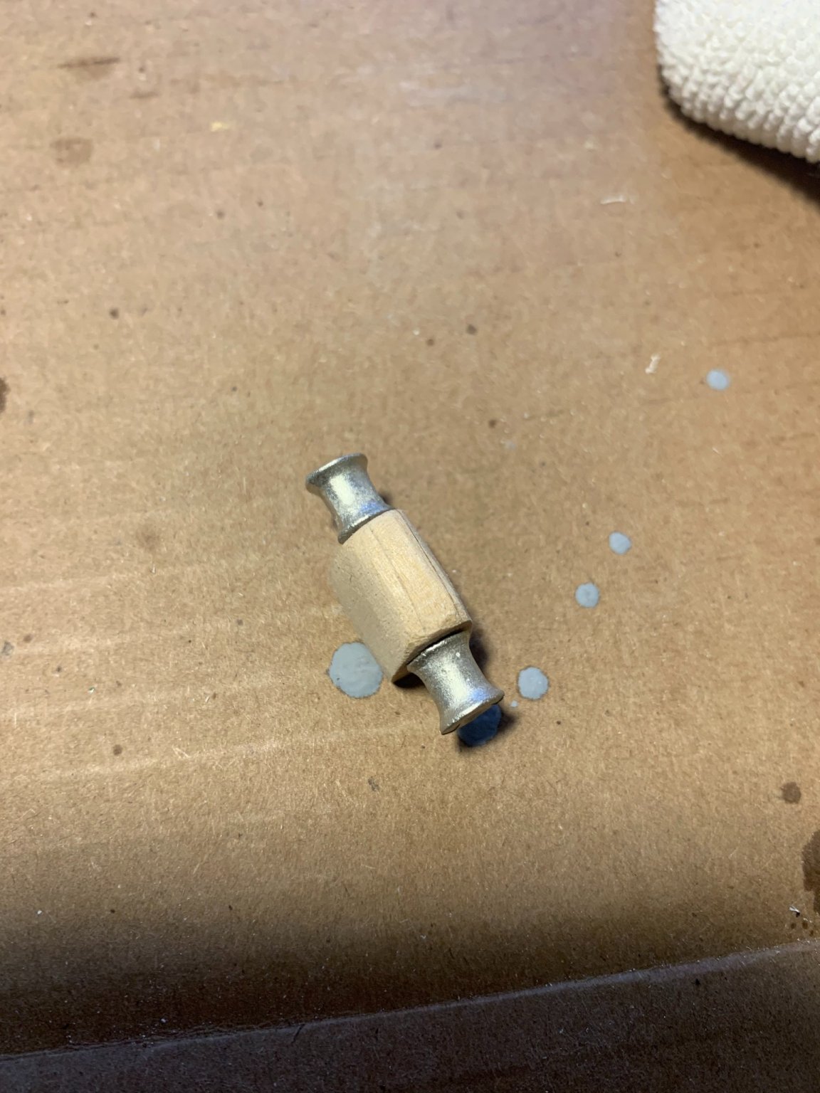
The diecast blocks that come with the kit are definitely workable, but after experimenting with some small single blocks (also from Syren), I am choosing to proceed with rigging using those wood blocks only. I will probably apply a light stain to the block and blacken the annealed wire. Below are some examples of the wood vs. diecast blocks (wood ones using 34ga stainless wire).
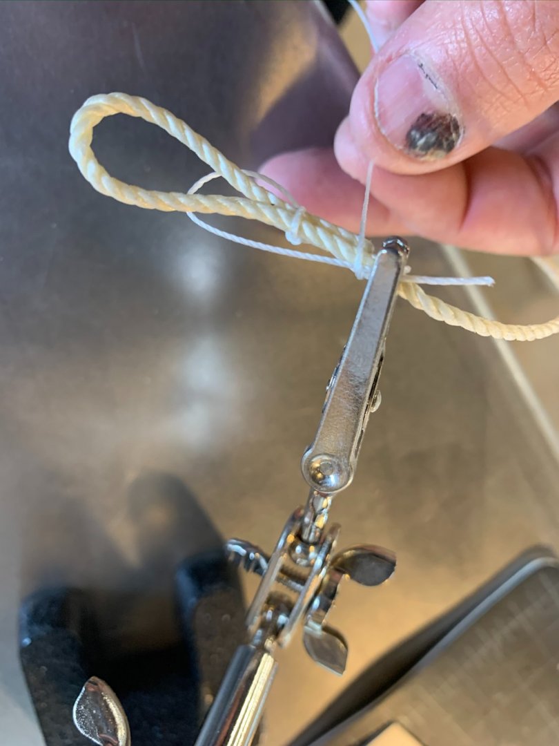
Below, showing applying seizing to the large dock line. Using alligator clip to hold things in place. Using methods as described by J Brent on his YouTube tutorials:
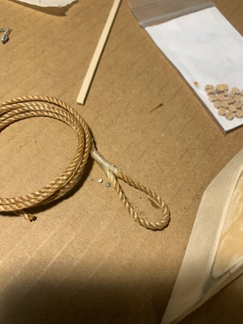
Further below, the final product after being stained (i.e. "weathered") with some wood stain
And completed:
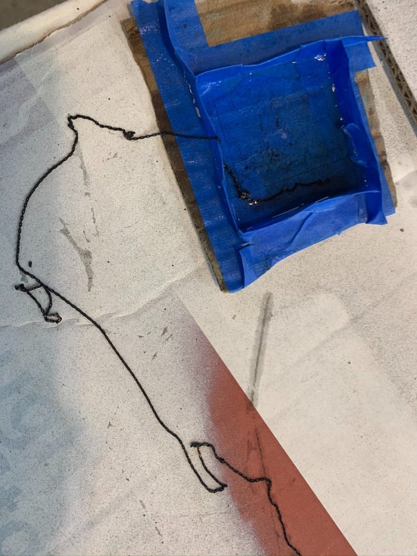
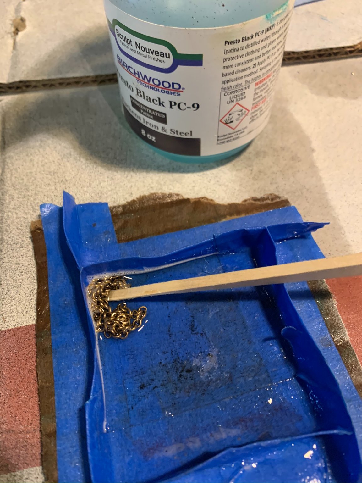
For all chain used on the model (at bowsprit and larger chain for anchor), I blackened with a solution prior to fitting.
Below is my blackening process, with finished product below.

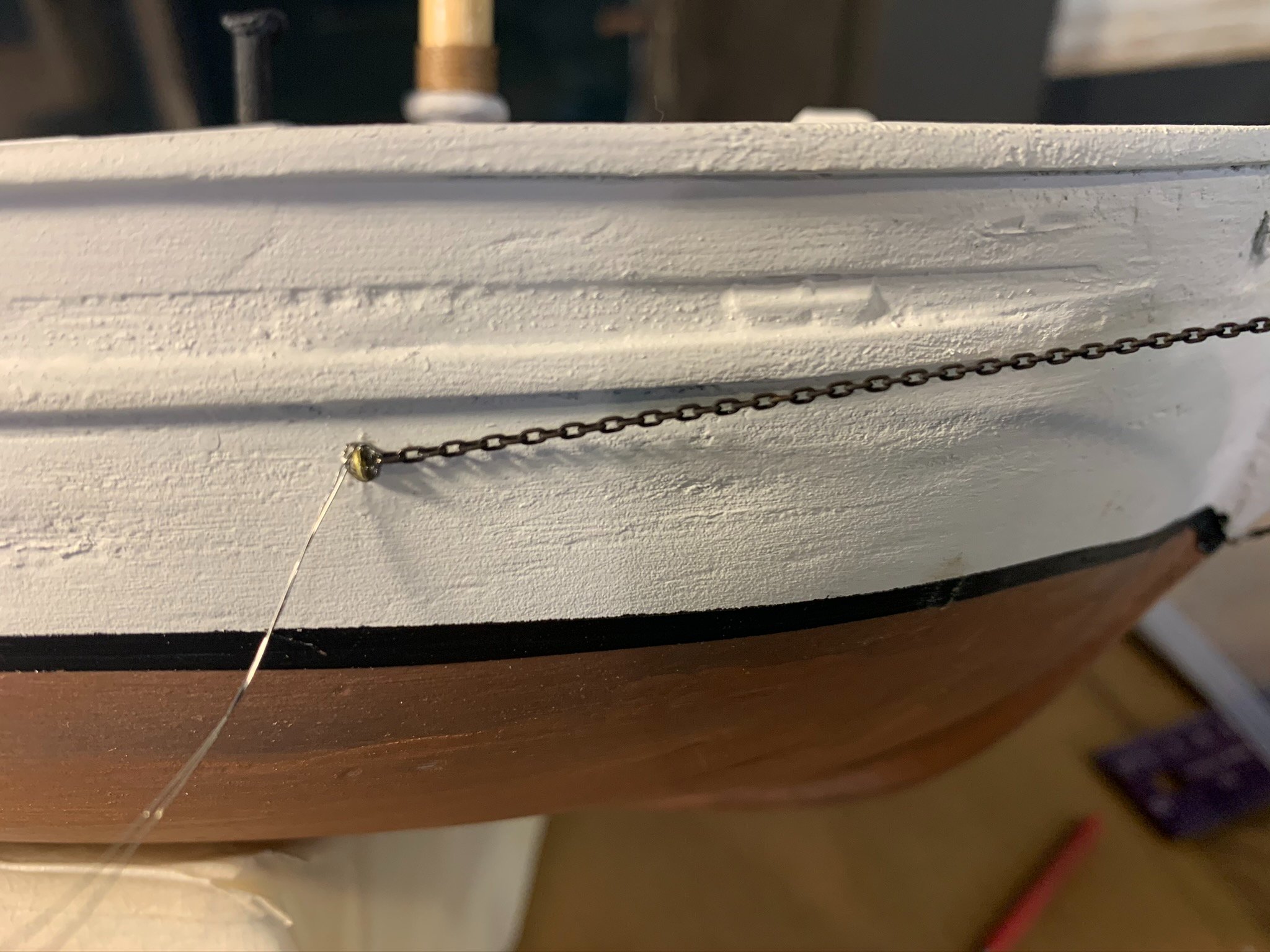
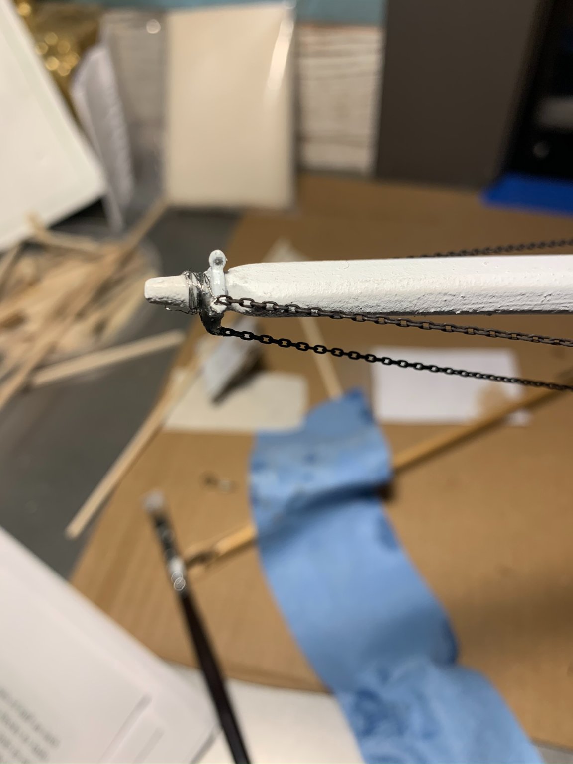
Using thin 34ga jeweler's wire, made a small loop in the hull-mounted pad eye for connecting the chains at bowsprit. Same method with connecting to the eye band loops at the forward tip of bowsprit.
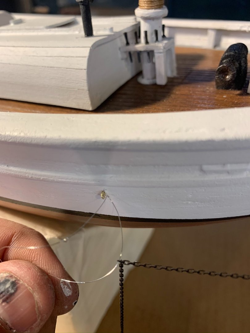
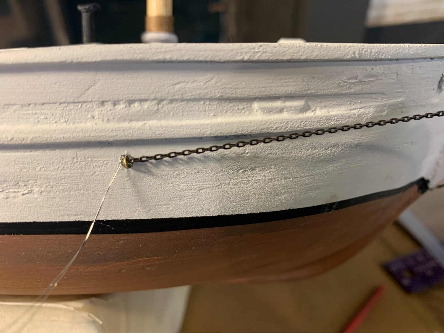
I left some length on the tail ends of the wire for re-tensioning at eye band should I need to later. I will clean up the tip of bowsprit and paint over any remaining wire upon completing the rigging.

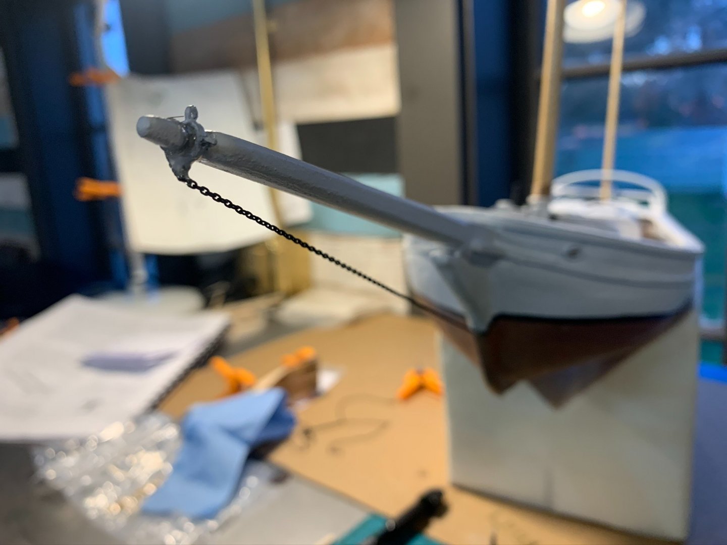
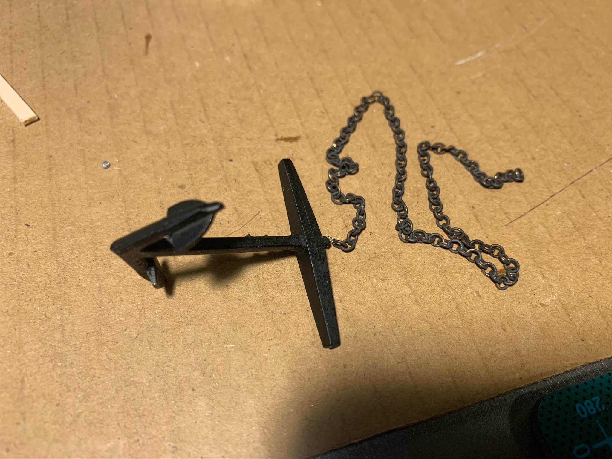
Below, completed anchor and chain, ready to be stashed away safely until the model is completed...

- Friday Dog, lmagna, dsmith65 and 2 others
-
5
-
Posting for my Days #13 and #14 of the Bluejacket "Spray" build:
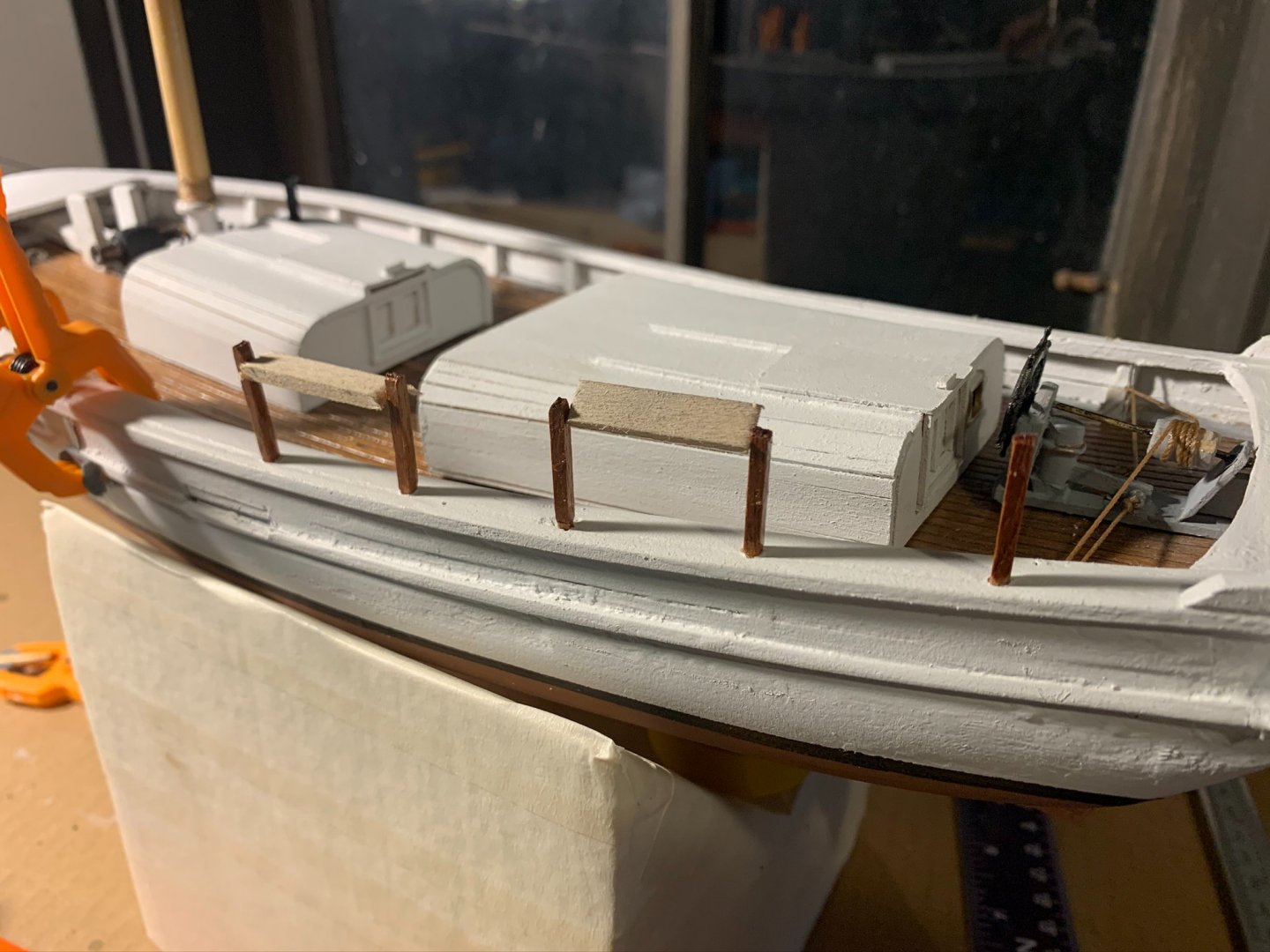
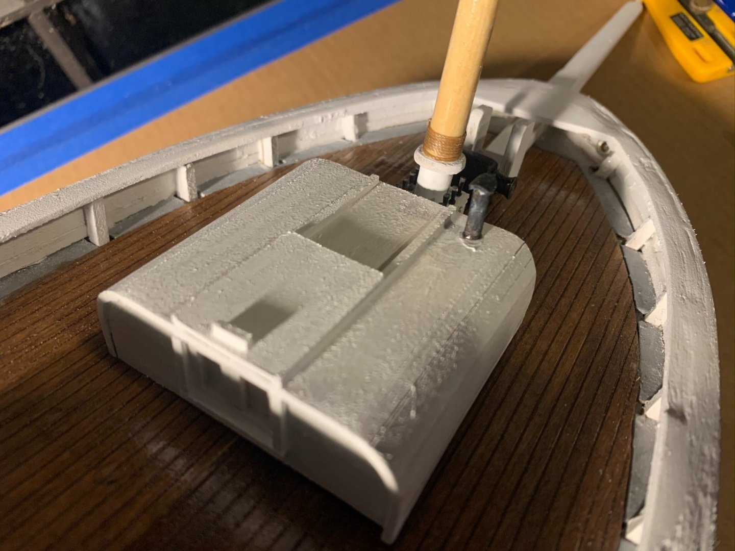
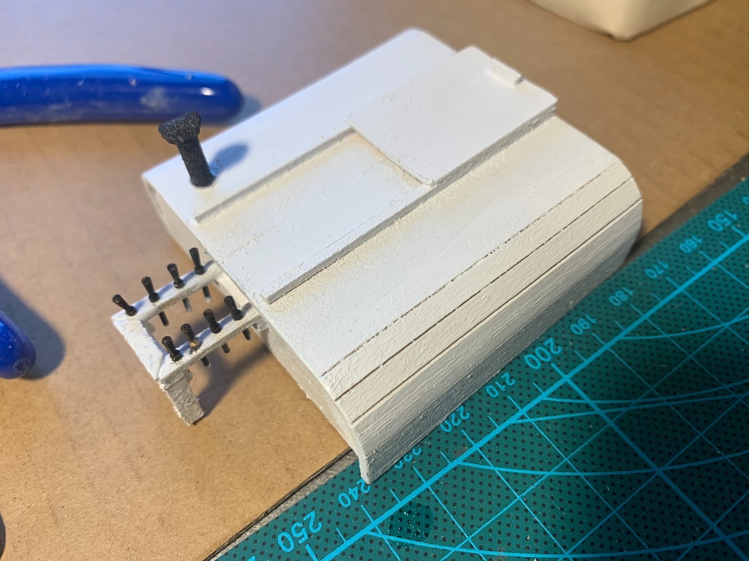
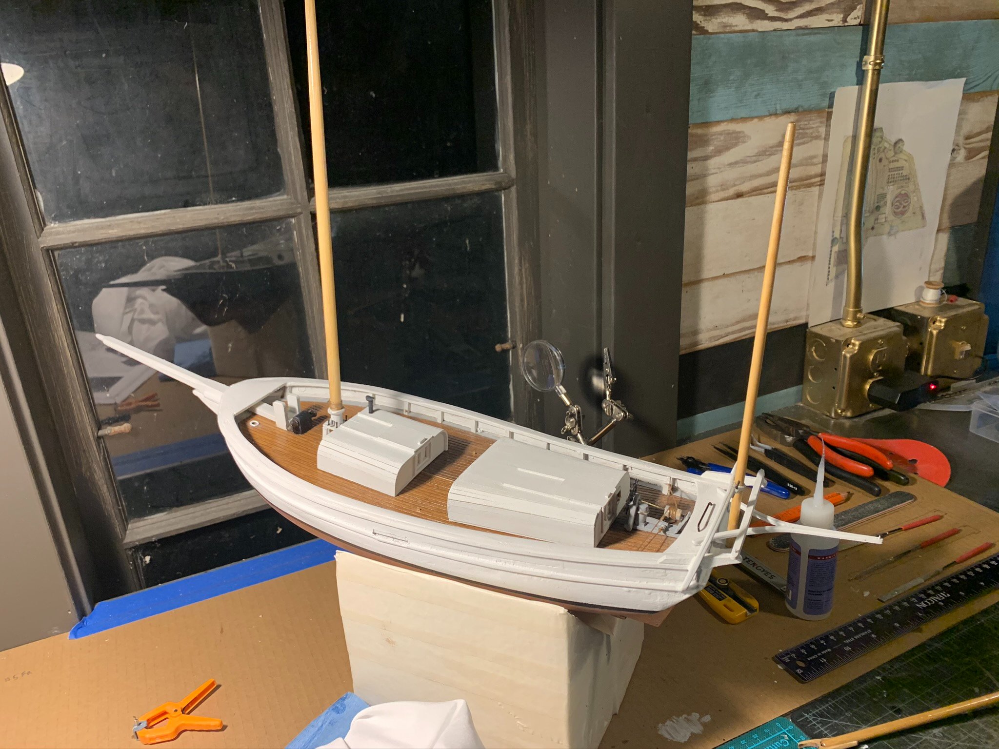
1. The previous build day concluded with completion of the cabins as well as the steering gear. The belaying rack is attached to the forward wall of the forward cabin, and fits around the mast. I thought it would be easier to build this piece first on its own, then attach to the cabin, then slide the whole thing over the mast. But first, I needed to spend some time shaping the bottom of the cabin to mate well with the deck. What I found was that both cabins were rocking back and forth from a generally high point along the center of the deck. What was needed was a good sanding starting in the center of the cabins and gradually working outward. Lots of test fitting, and in one place on the forward cabin, I placed a small strip shim to bring up one edge. Below is a picture of the completed belaying rack (the brass pins were soaked in a blackening solution). Per the instructions, I made the vent pipe out of 1/8" dowel and small piece of construction paper.

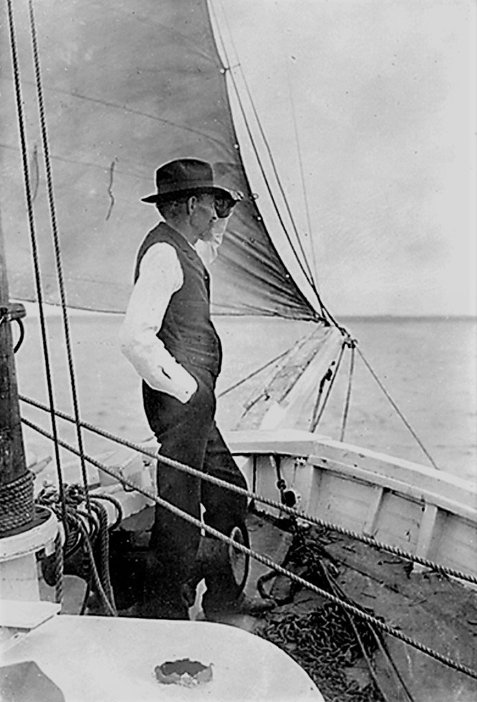
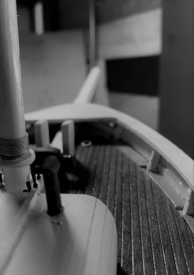
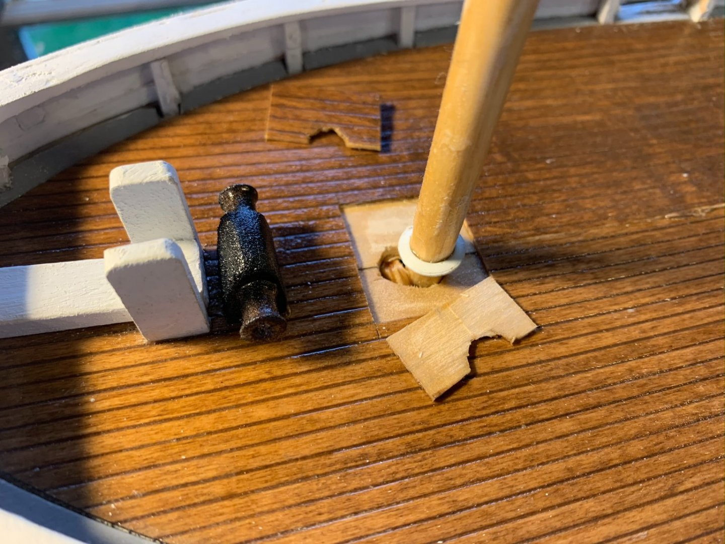
NOTE: I got to this stage, and was just about to glue the cabin in and started looking at some reference photos of Spray. I found this one picture below of Slocum standing at capstan and noticed the mast had a substantial seat for the boom jaws that look to be rope-lined and painted white below the seat. I wanted to replicate this as best as I could, and needed to do this before sliding the cabin/belaying rack over the mast. So, that was the next task..
To do this, I cut a small circle out of 3/16" thick scrap basswood, and made a 5/16" hole in the middle. I sanded with a small file until it sit snug at the approximate height on the mast. Wrapped a few turns of stained line above the seat, and painted the lower areas white. Below is the final result, and my attempt to recreate the same perspective from the Slocum photo.
Here is the completed forward cabin.
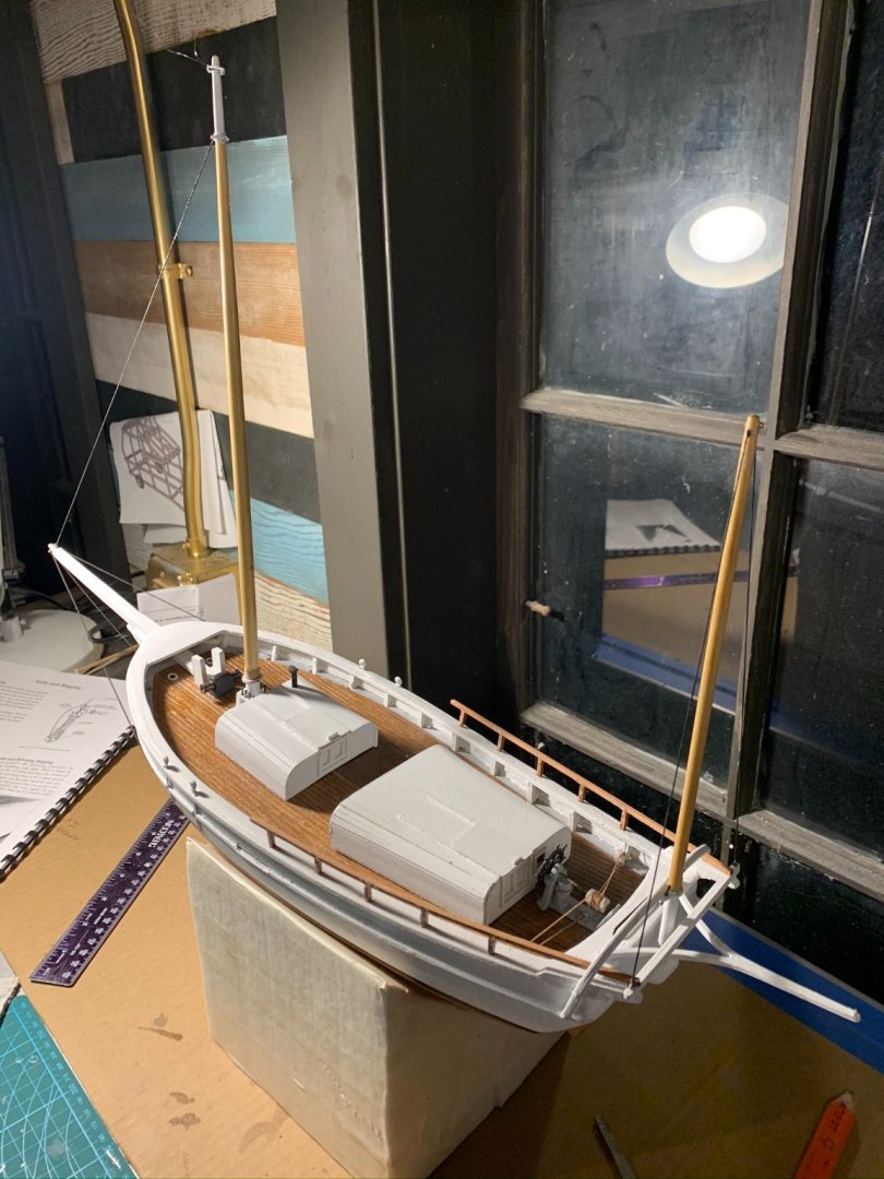
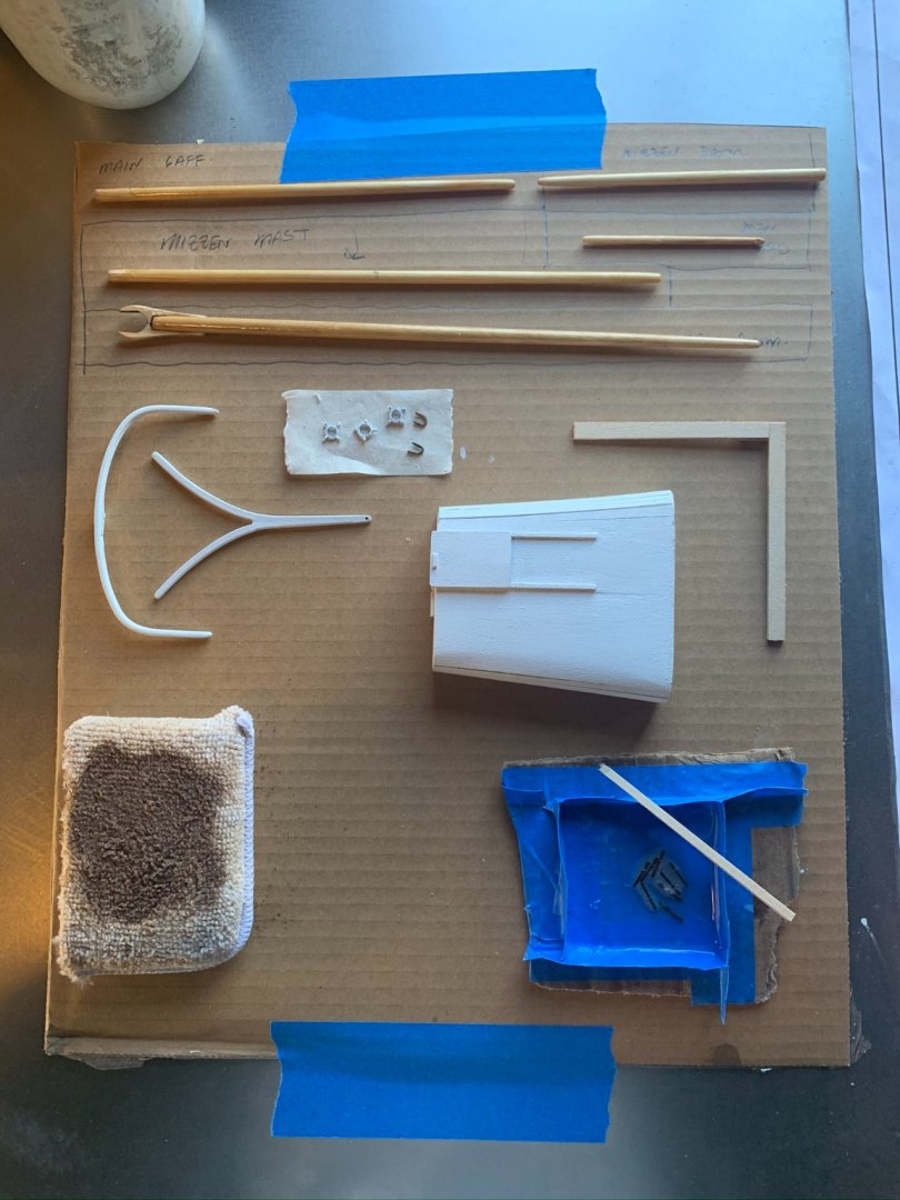
2. I will be moving forward with assembling the aft supports necessary for the mizzen mast rigging after the cabins are installed. I took some time to put one more coat of spar varnish on the mizzen mast, mizzen boom and gaff. The hole in yoke that supports the mizzenmast needed to be drilled out a bit for the correct fit. (A step drill bit would be smart here, but I just gradually worked up in 1/32" increments to the appropriate size. The worry here if you're not careful is you could easily bend the metal if your drill catches too much material). The wishbone and yoke are painted white and ready to install. Below is my prep area for these parts (you can also see the little blackening bath I made for the brass parts).
3. Placing the aft cabin was much the same process (less the belaying rack). I found the cabin needed sanding in the center to fit a bit more snugly to the deck.
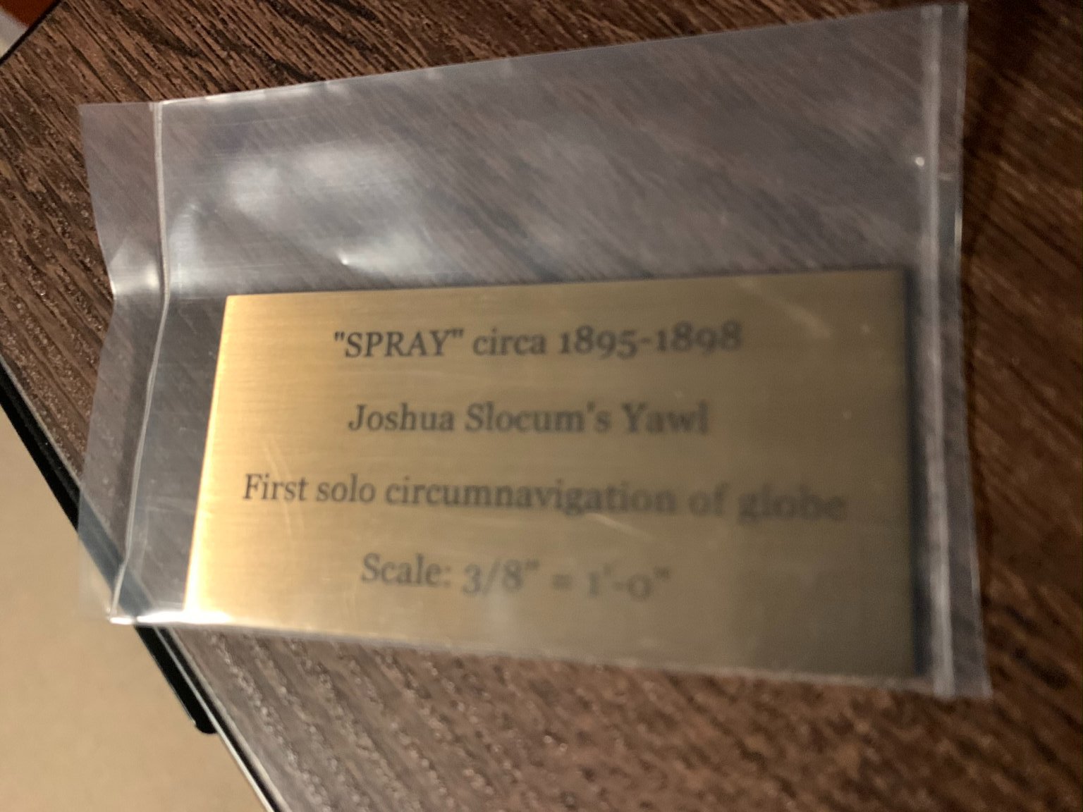
4. In the meantime, I just received this small engraved plaque I ordered for the future mounting plate.
I am sure there are many others sites that can make these, but this was from the EnMEngraving company:
https://www.amazon.com/stores/EnMEngraving/page/7E19C564-3C46-4768-BA8B-A1B0DB5D7C2D?ref_=ast_bln

5. Shaping the brace brackets that support tie brackets (cut from 1/8" thick basswood).

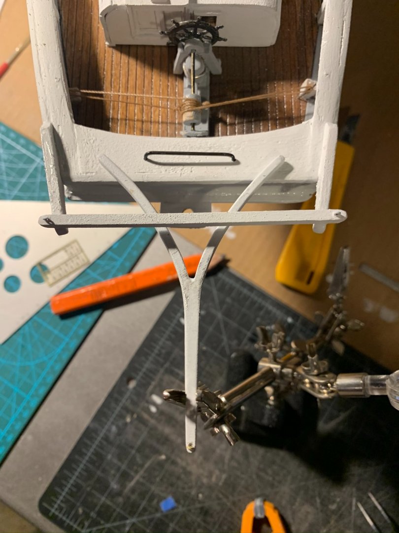
6. Like others have commented, there is no real description of how the wishbone is to be installed to the transom, so I just assumed it should be glued. To do this, I used a soldering station "helping hands" to clamp and hold the part down. I applied glue and let set for some time. If this proves not hold tight, I will look at cutting some grooves into the taffrail that would fit the wishbone arms and provide more structural holding for the piece. We will see...
*Also below in this picture is the main sheet traveler, built and bent from the brass rod supplied. The instructions tell to paint white, but I like the look of the blackened brass in this case.
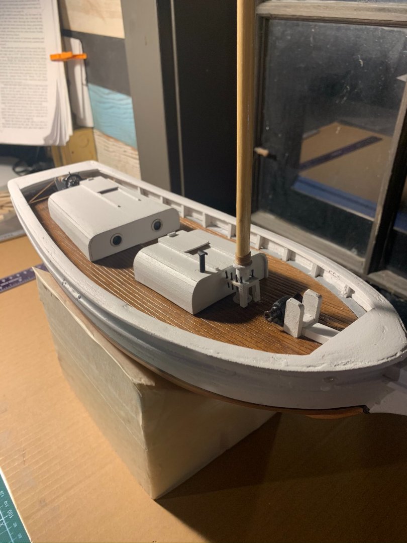
7. Test fitting the mizzen mast...some small adjustments to the angle of the yoke needed. I double checked the distances from the centerline base of main mast to mizzen (at top and bottom), and found them to be within 1/8" of what the plans indicate. Relative to the waterline, the mizzenmast appears to be 90 degrees (perpendicular), whereas the main mast has a slight rake aft.

- Duanelaker, lmagna, BobG and 1 other
-
4
-
8 hours ago, lmagna said:
Nice work Josh
I was Lucky enough to get the Laughing Whale version of what appears to be this same kit from Ron here on the forum. I have known of Joshua Slocum and the Spray since my teen years when I read his book "Sailing Alone Around The World", and it made me a life long fan.
I will be following Tom's and your builds with considerable interest.
Thanks for the interest in the build Lou!
-
21 hours ago, Tomculb said:
Really enjoying your posts Josh, and great work! You're at a point where you are passing me, and moving at a much faster pace. Now I get to learn from your challenges and good work. I finished the cap rail, got a few coats of paint on the rails and hull, and this morning I glued in the waterways (or margin planks). I will do another post within the next week or so. Your blog is in the correct forum--1850 to 1900. When they changed the forums around, mine got put incorrectly into post 1900 for some reason.
Incidentally, my mask rake seems to have worked out correctly when locating the hole as shown in the plans. The rake is definitely forward relative to the deck (which slopes upward at that point), but it is slightly aft relative to the waterline.
Looking forward to more of your posts.
Thanks much Tom! I have enjoyed reading your posts, and have learned a lot from them. I look forward to seeing your progress as of late! The rigging and sail-making are going to be challenges for me, so I will definitely be reaching out to you an others for feedback regarding those tasks! I'll post another update soon by the way. Best, Josh
-
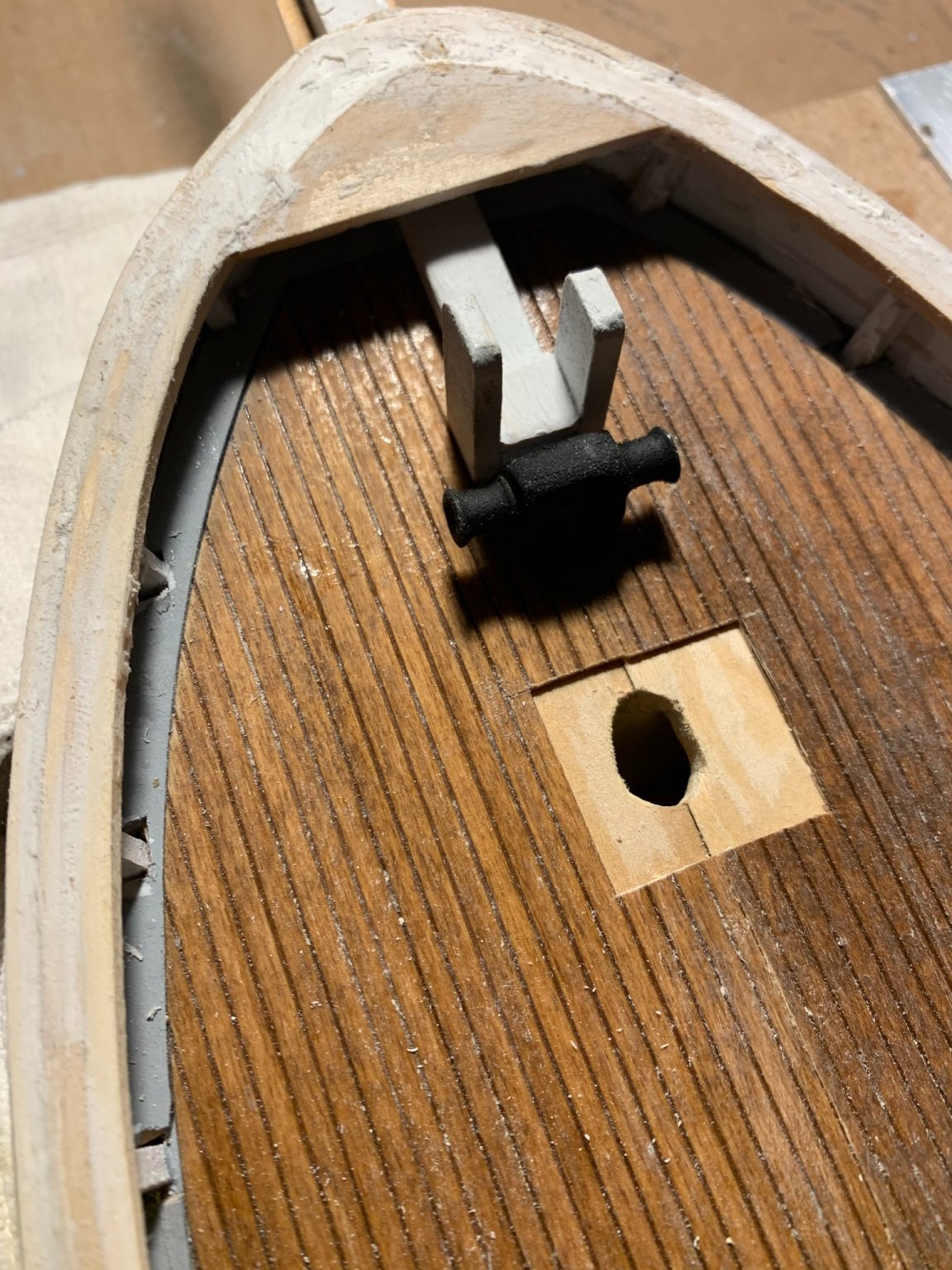
Day 12 build log:
1. Finally got to setting the mast. Took some final measurements on the correct rake aft, and placed a small wedge in the enlarged deck hole to correctly position. (Recall from previous posts that my original deck hole placed the mast in a slight forward-leaning position. Needed to enlarge the hole towards aft to correctly position).

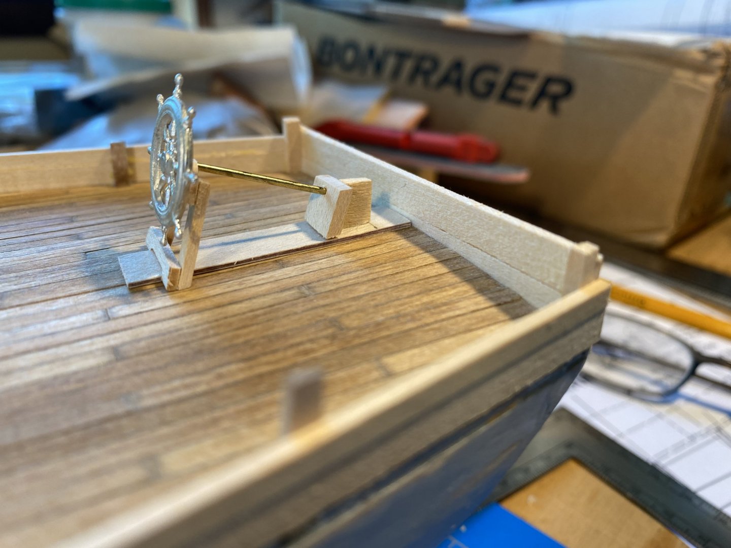
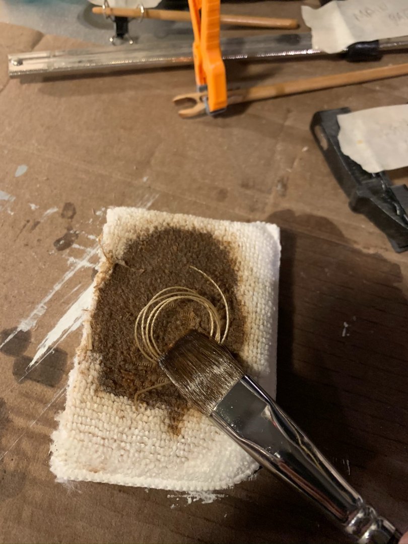
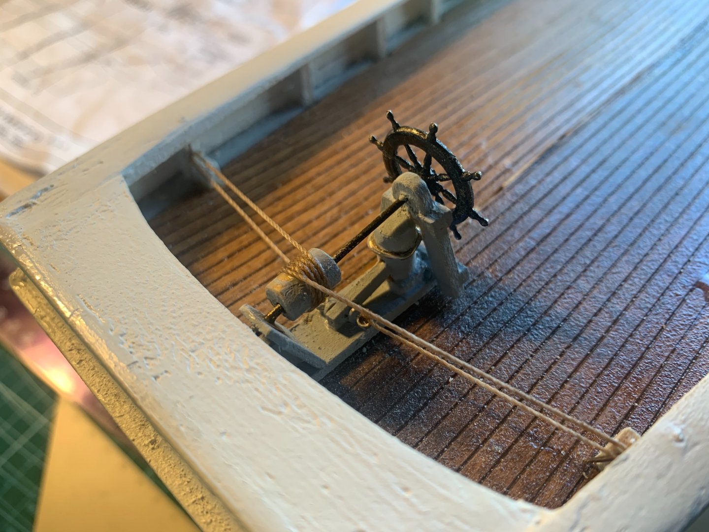
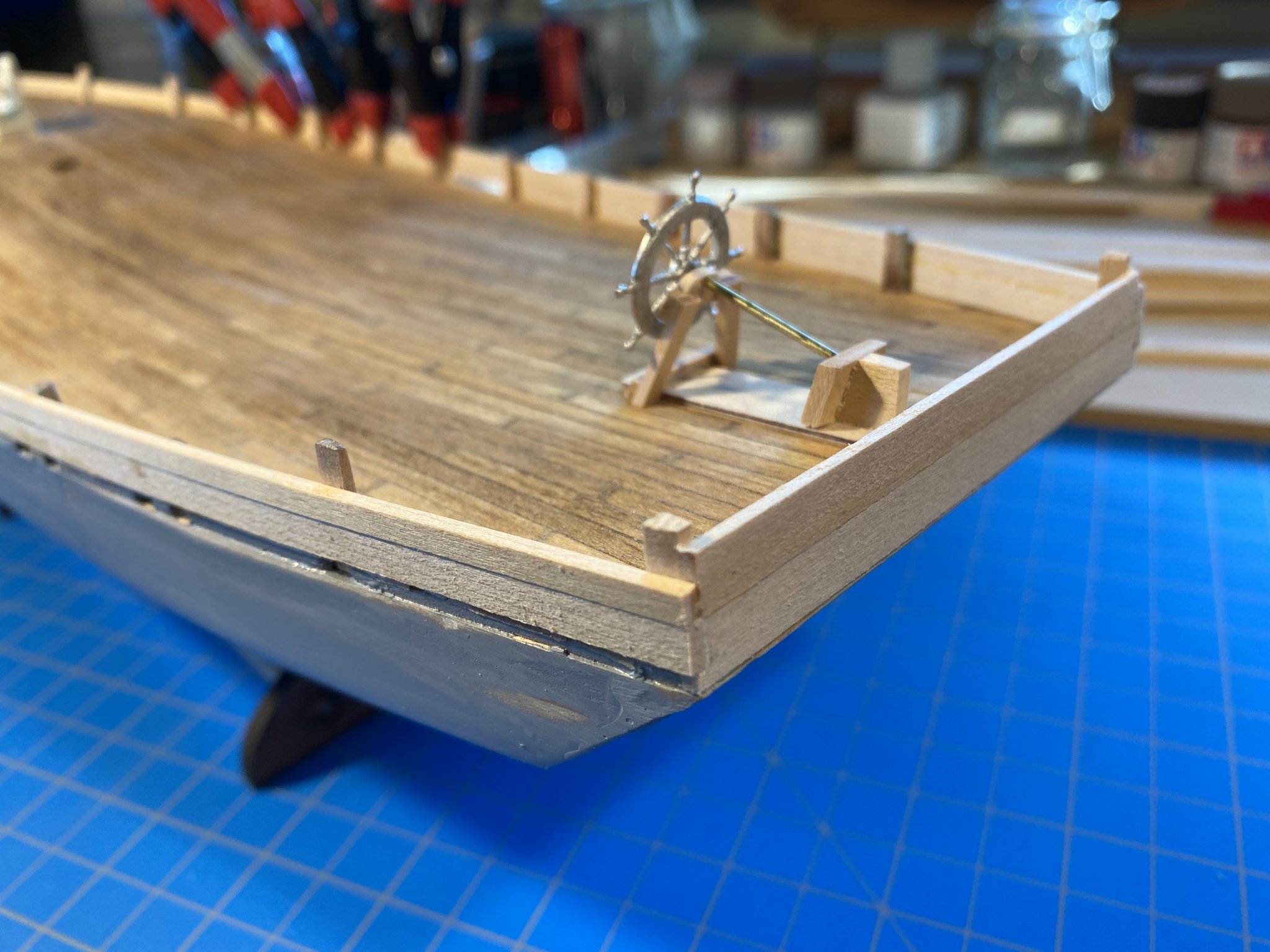
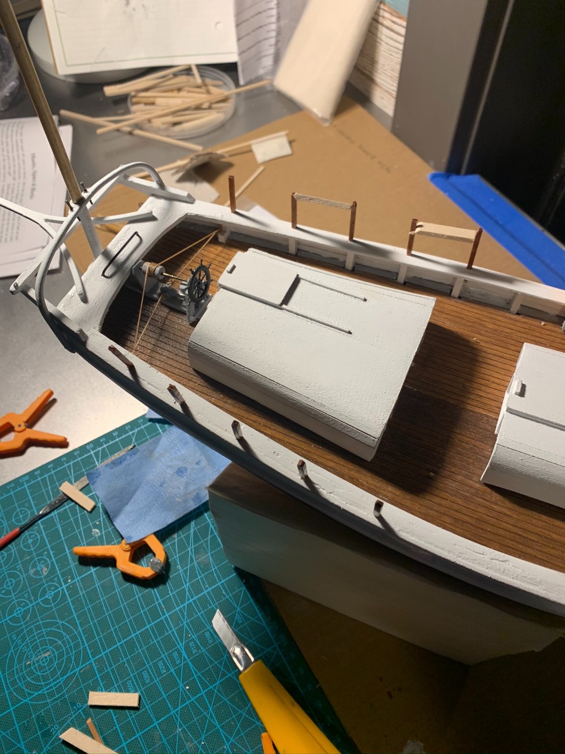
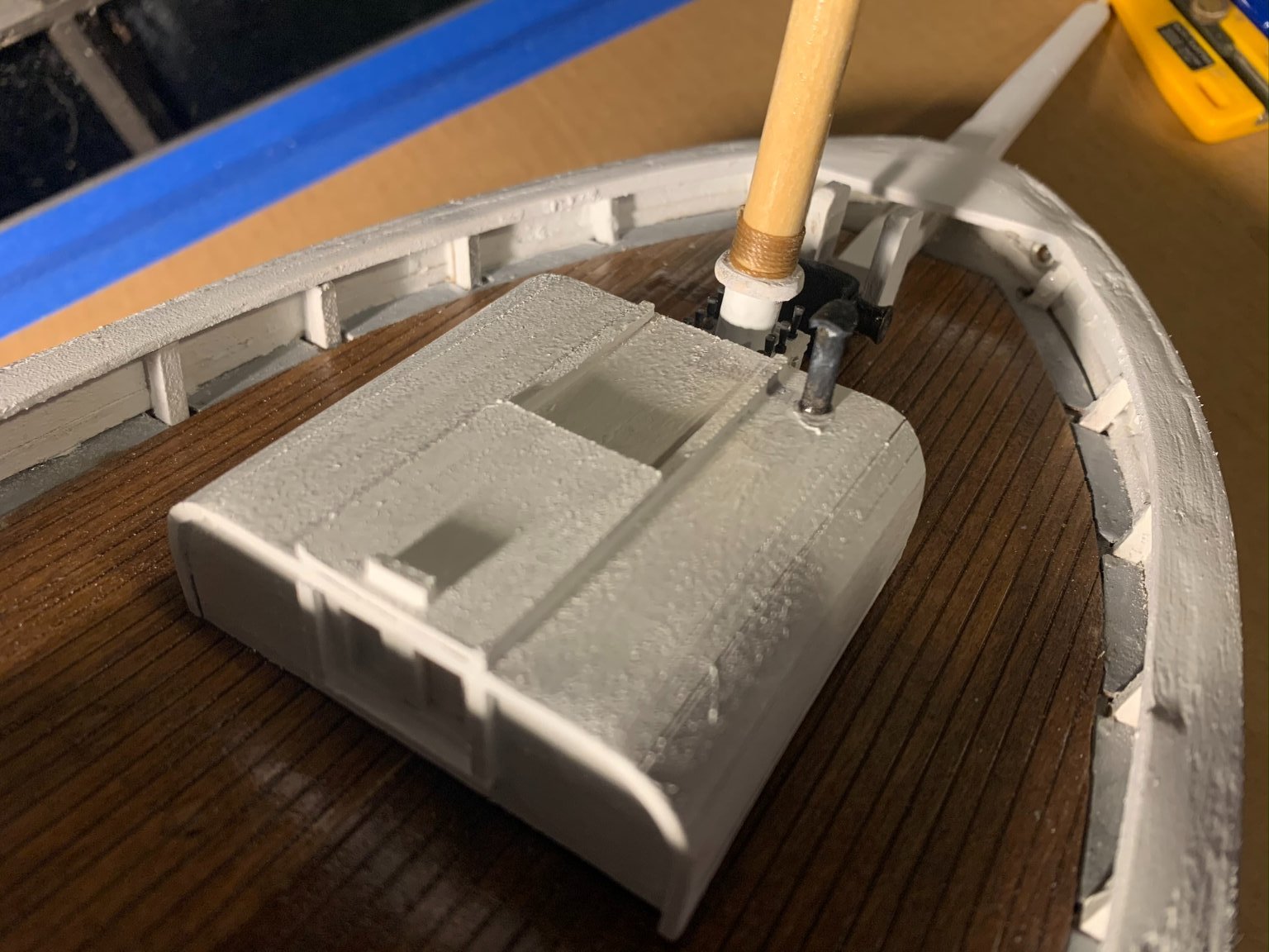
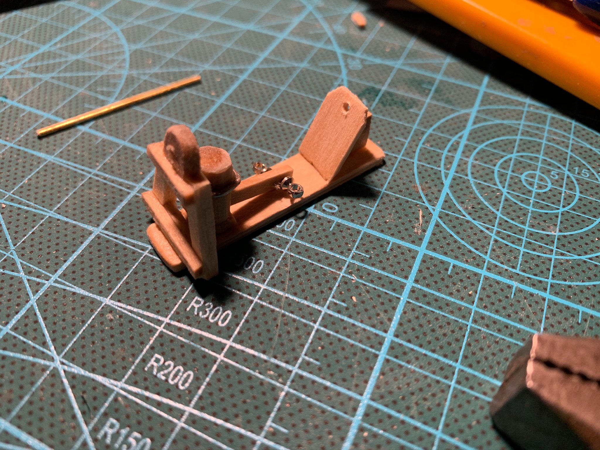
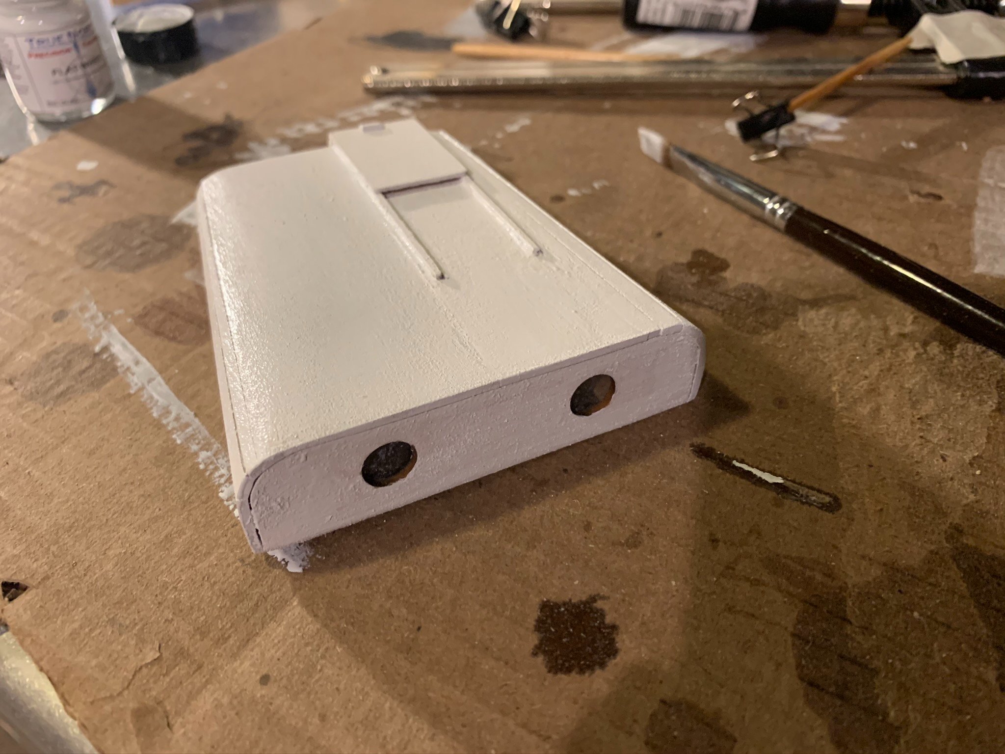
2. Next, per the instructions, is to assemble the steering gear. The parts are small and rather delicate, so it just takes some time to get things right. I chose to paint all wood components gray primer as the instructions would suggest; although I have seen some images of Spray that make it look as if Slocum had all of this painted white. The tiller control line was "weathered" by staining it on a pad with Minwax "Early American." This I found, makes for a more realistic hemp rope look. The brass dowel was soaked in some Sculpt Nouveau blackening solution, and the wheel painted flat black with rattle can.

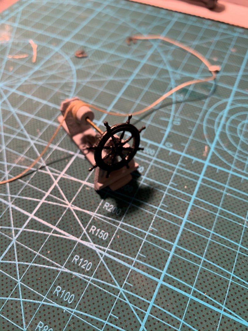
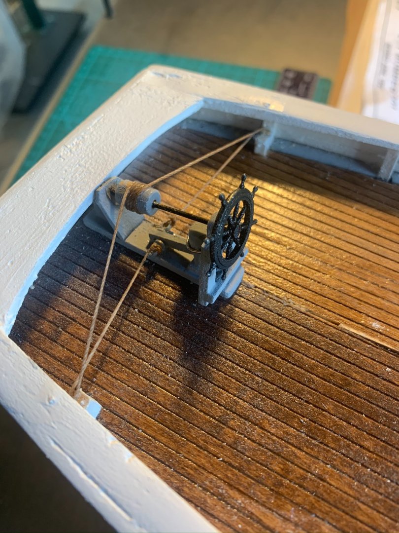
3. With this steering gear, there were some lessons learned. Admittingly, I had some issues with rigging the stropped blocks on either side of the rope controls. The wire that was supplied with the kit was too large to correctly strop, so I simply tried to glue the block down and tension the tiller line. Not surprisingly, this pulled out every time. In an effort to get this piece rigged and completed, I made a solution where I drilled two vertical pins through the cap rail and down to a support abutting the stanchions to catch the tiller lines. The serves as a structurally sound solution, albeit not a completely accurate representation of the true rigging mechanics. I may attempt to "cheat in" a block to visually approximate the more accurate condition. For now, this keeps me moving forward.
NOTE: the aft most end of the barrel tiller control is meant to sit below the taffrail. Something in my measurements made this support piece higher than the taffrail - thus not allowing it to sit fully aft where it wants to be. Consequently, the whole steering gear sit forward of their intended location about 3/16" of an inch. With the aft cabin in its correct position, it is a bit crowded it seems. I will choose to split the difference on the clearance required at wheel and the clearance between cabins (where dinghy sits). The location of the forward cabin is pretty much determined based upon the mast and belaying rack, so there is not much I can do there to buy some space.
** Below is a completed image of steering gear. Before gluing in place, I gave the deck surface a clean with some mineral spirits and recoated with a fresh layering of the "gloss" varnish supplied with the kit.
- Stimpy, ThirdCoast and Duanelaker
-
3
-
Day 11 of the build:
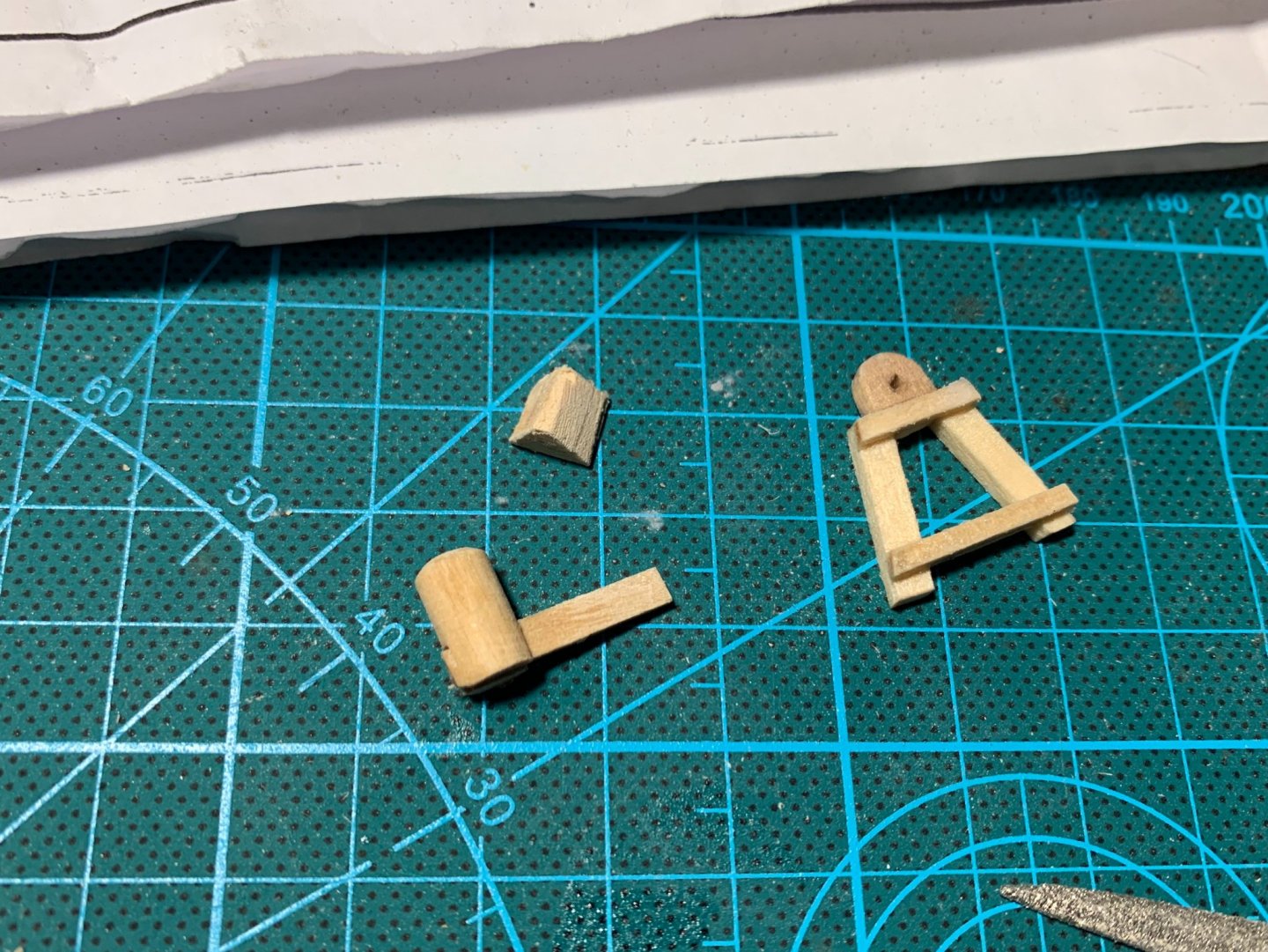
1. Was working on assembling the main boom jaws, and took to sanding them to a more curved and believable shape. Snap!! (They are quite delicate)...so needed to re-glue and re-affix. Below, you can still make out where the crack is. Before any final assembly of the boom, I will get after the jaws opening with a small sand paper and jewelers file to smooth out this area.
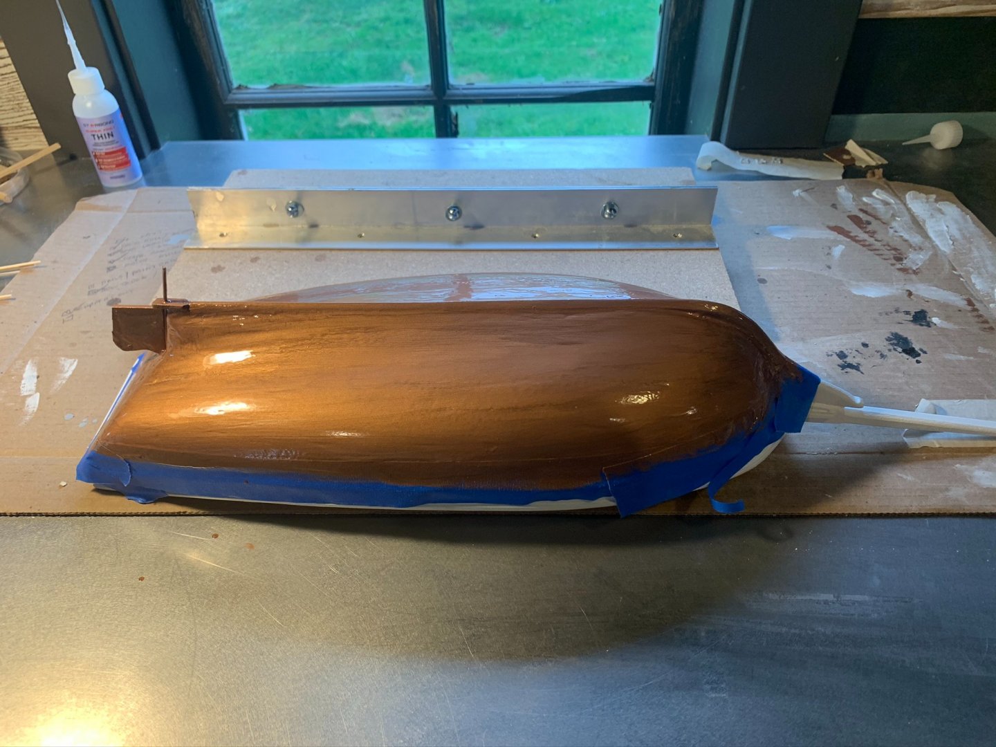
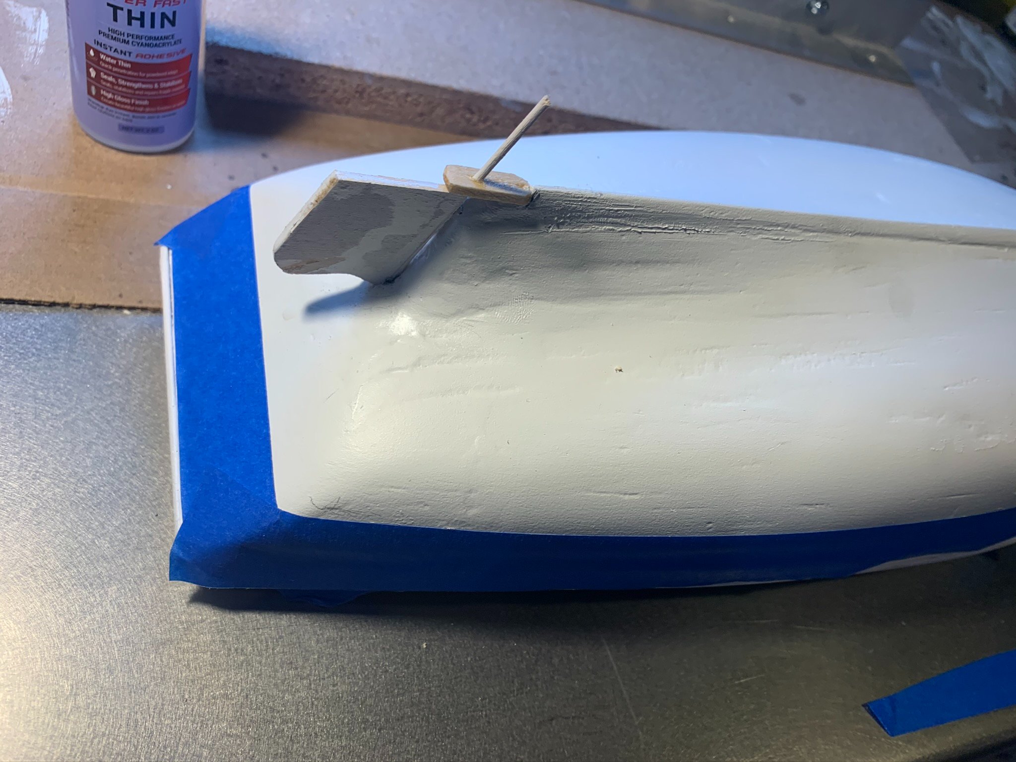
2. Unfortunately, my rudder encountered a similar fate as it cracked in half as I removed it from the clamp that was holding it while gluing the rudder post to it. I had to trace another rudder out of scrap and start over. Over some fussing around with the small dowel that attaches to the rudder, I was able to get it mounted to the gudgeon and glue in place. Also, below you can see some prep starting for the copper bottom paint.
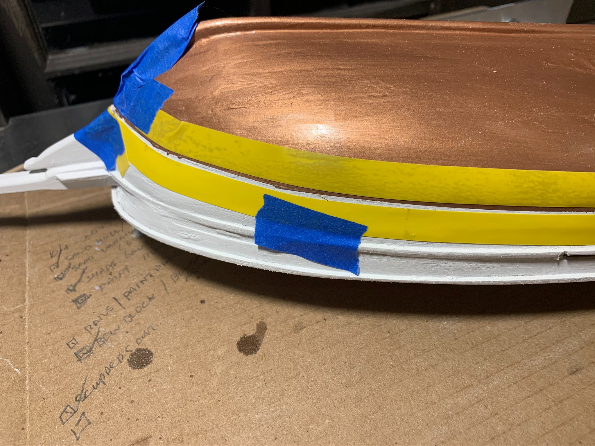
Although I didn't get a picture of it, I established the waterline again by making measurements on the plans and then transferring tick marks to the hull. Then "connected the dots" with the blue painters tape.

3. After one more fine sand of the hull below the waterline, I started with the bottom copper paint. Found the paint to be quite viscous (perhaps because the shop is starting to be a bit cool); so as alluded to in a previous post, added some mineral spirits to the paint cap and mixed in a bit of the paint. I found with a couple drops of spirits to about a 1/2 tsp of paint to be a good mix. I applied two full coats to the hull and let to dry.
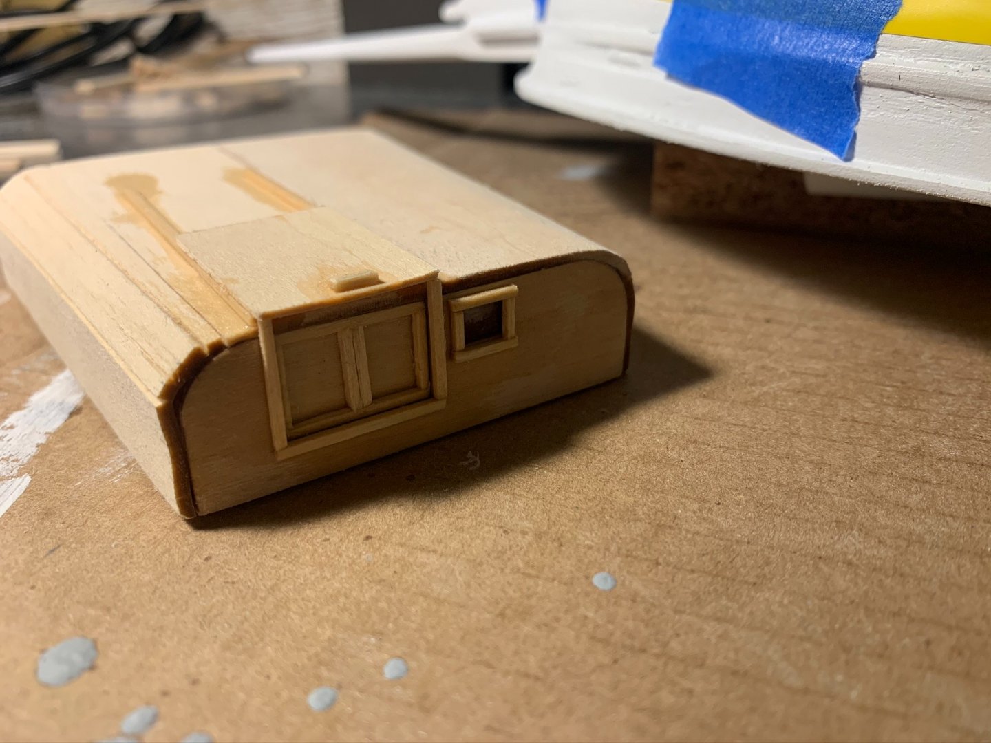
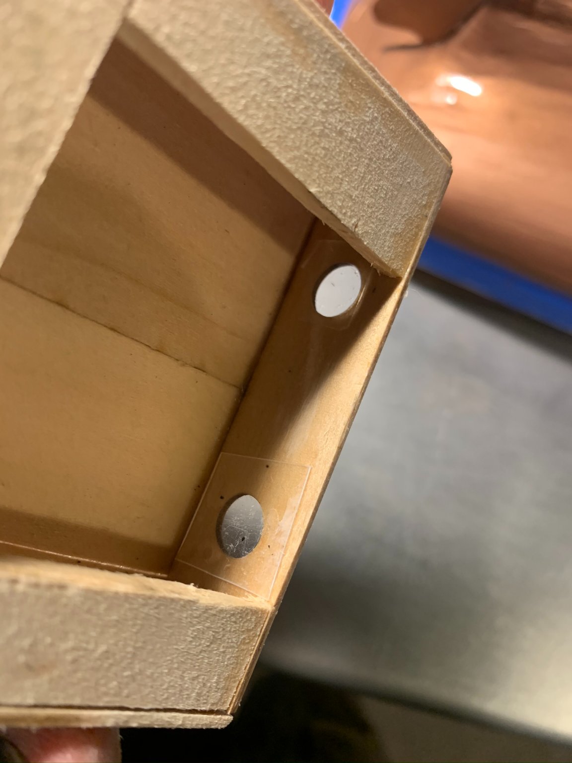
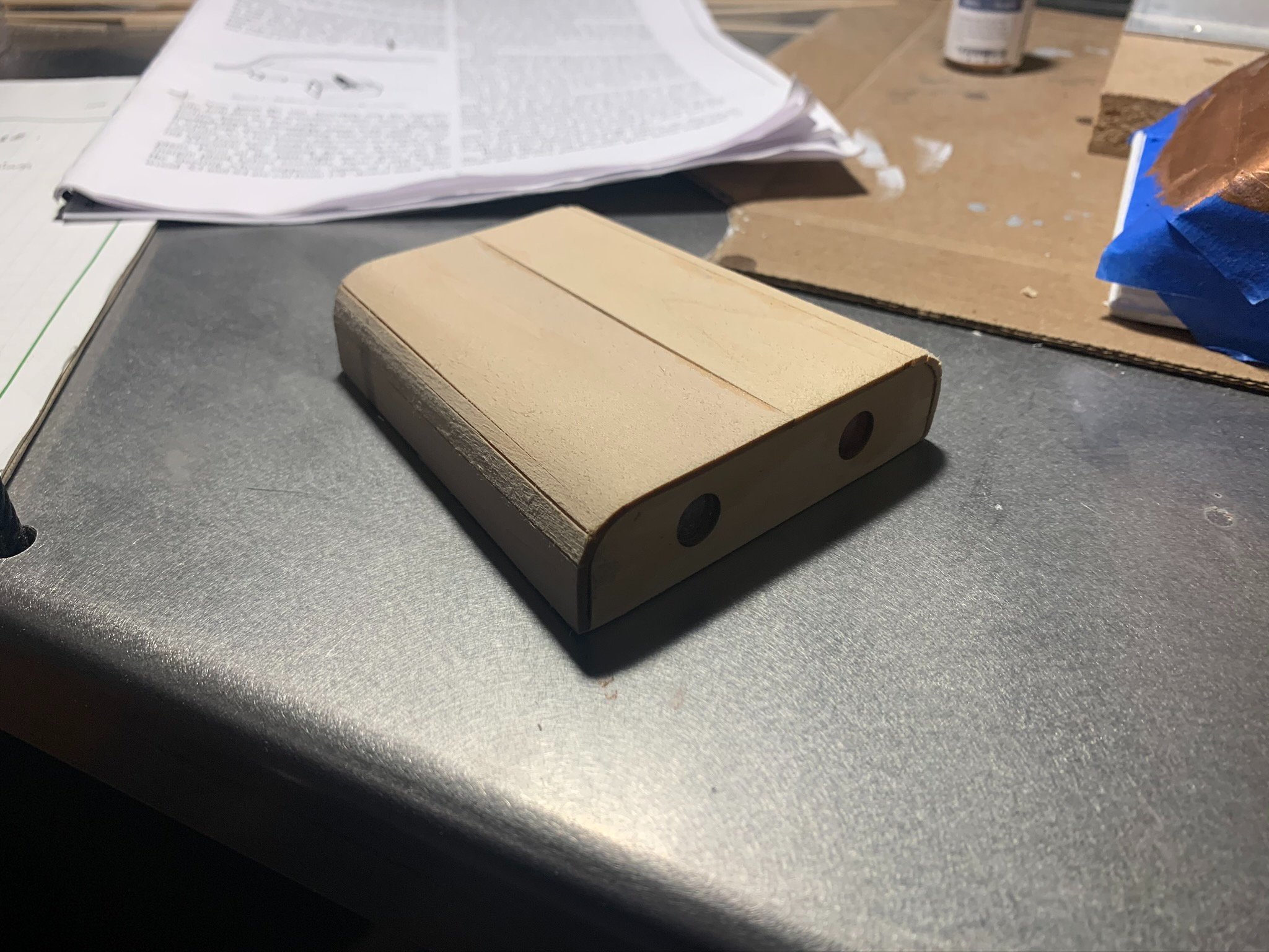
4. While waiting for paint to dry, I focused some attention on the cabins. I found the pieces (which are laser-cut), to nicely mate with each other. One addition made was to make a base which fit inside the interior walls of the cabins to allow for more rigidity and also more gluing surface area. Below, you can see the base and access opening made for the larger cabin. Was also experimenting with placing a small piece of acrylic at the portholes to simulate glass. NOTE: This was before I realized there were diecast porthole inserts that are supposed to be installed. I since removed these plastic "windows," sanded out the hole a bit and installed the diecast porthole frames...then put in new plastic for the glazing.

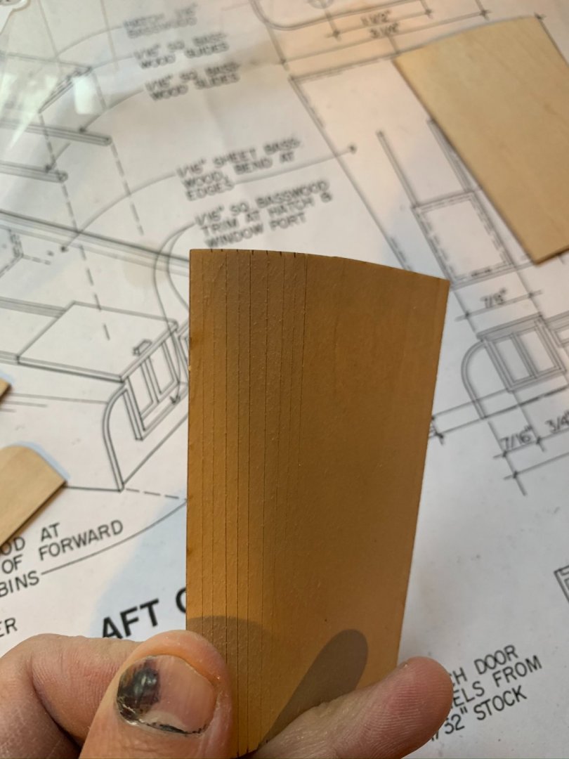
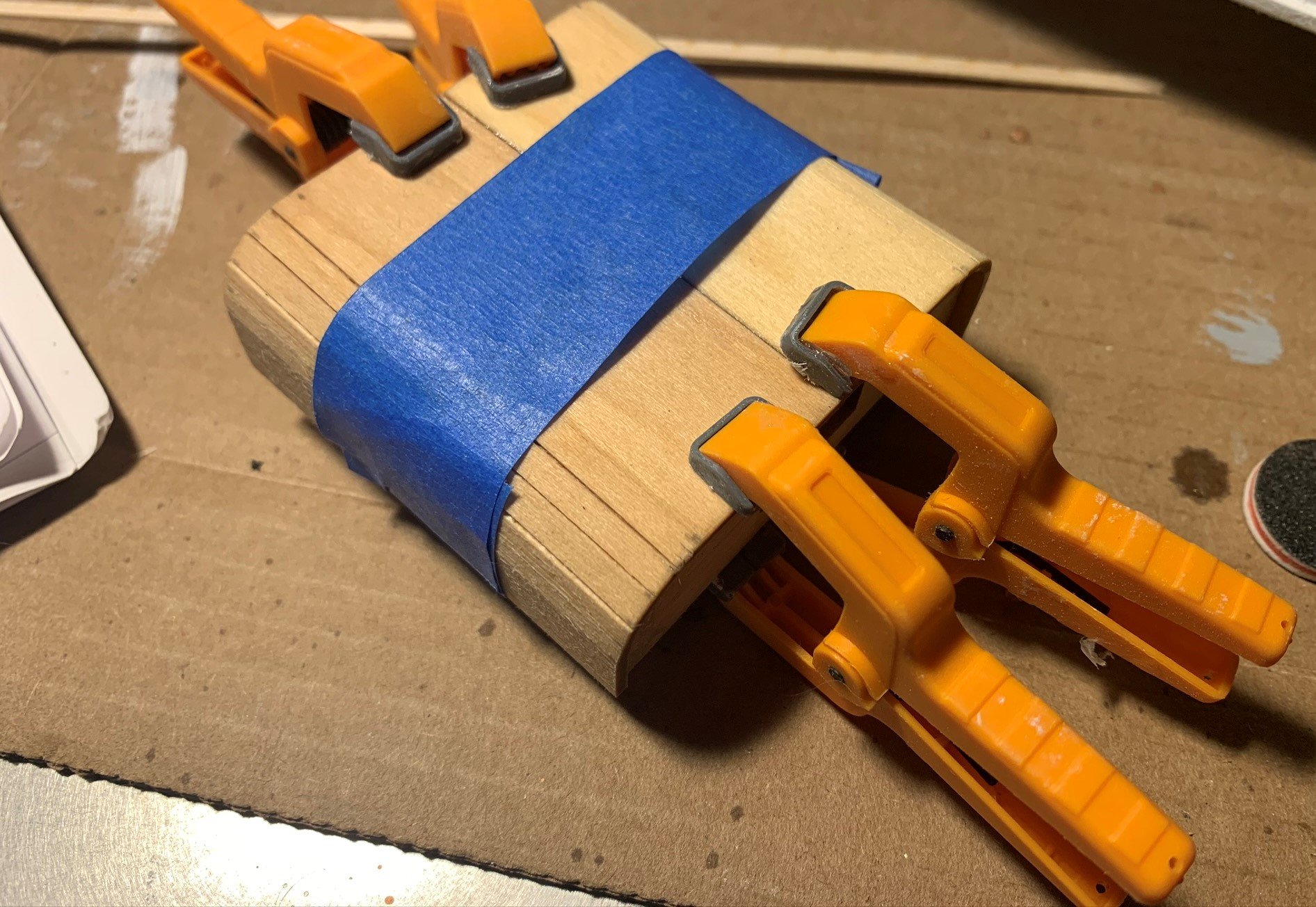
Where the roofs curve down towards the vertical wall plane, I scored some small lines at 1/8" increments to allow for an easier time bending. That coupled with a short soak, made the basswood sheet pliable enough to make the curve easily.
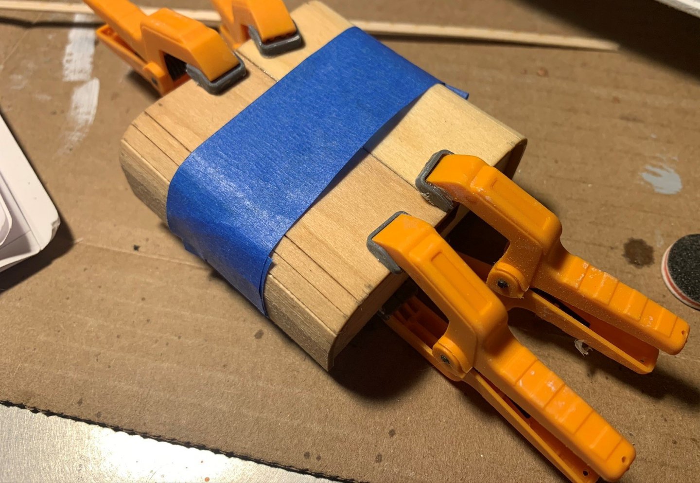
Working from the center of the cabin roof, applying small amounts of glue and working towards the curves seemed to be a good strategy. Once the walls had been glued, I wrapped and braced the cabin with some painters tape and clamps:
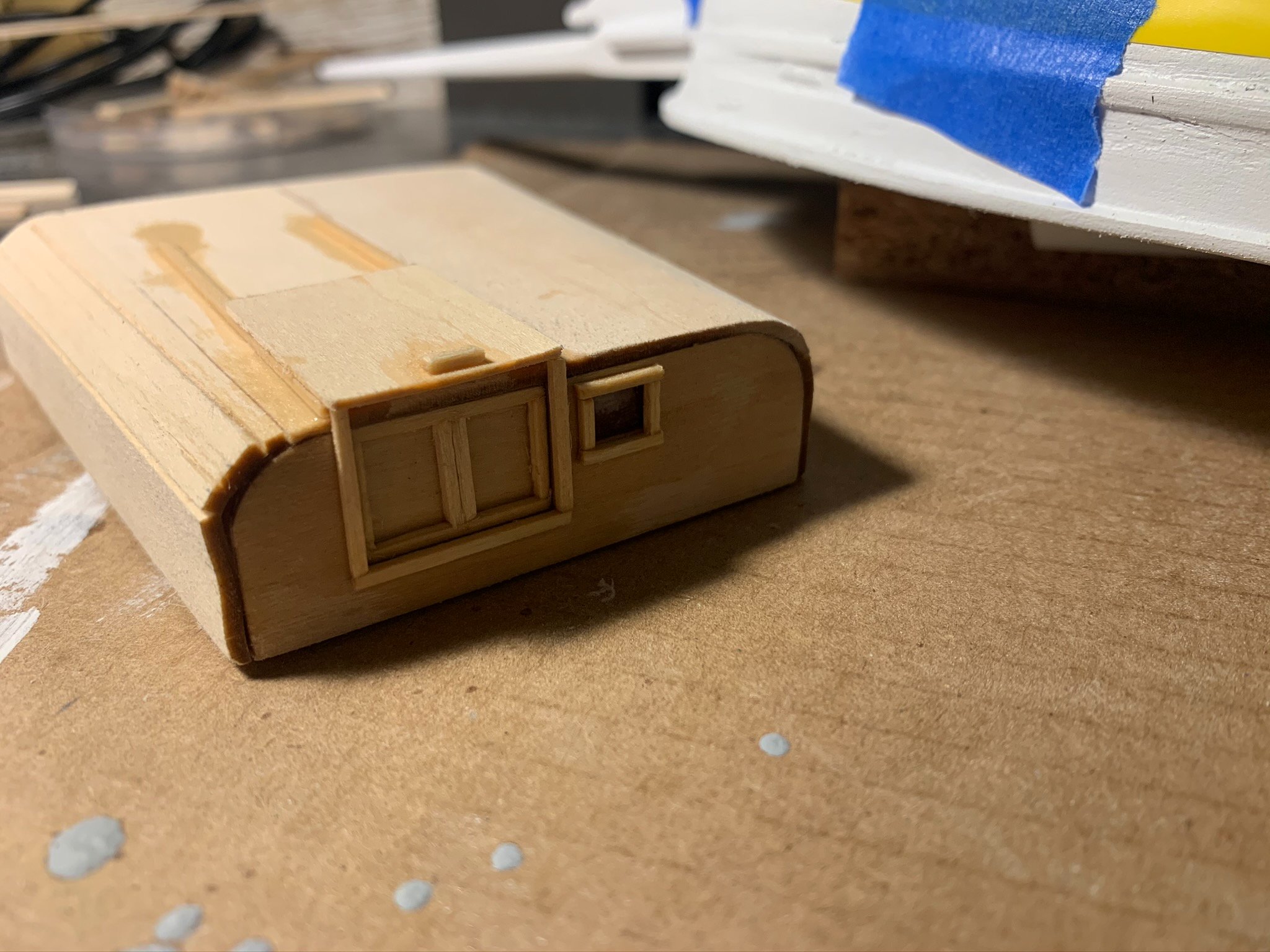
There was a little bit of trimming necessary at the bottom of the cabin where the walls met the base. No more than 1/8" was needed to be trimmed from each side. Trimming out the hatch covers, rail and casing was with 1/16" x 1/16" stock... Then some white paint...


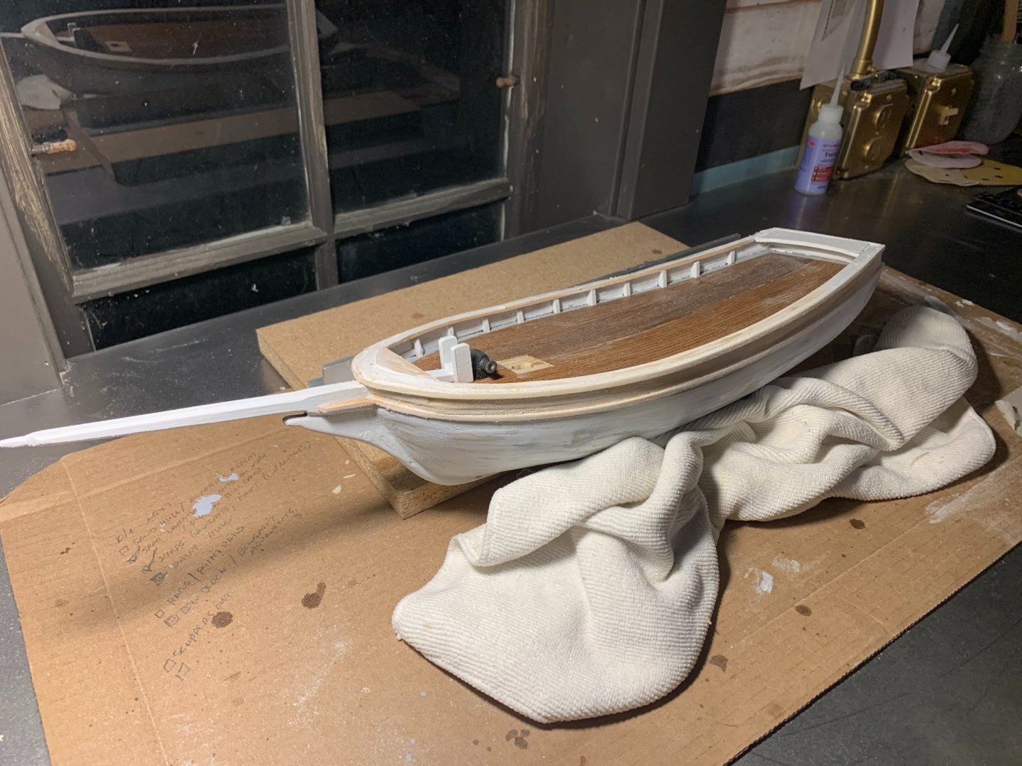
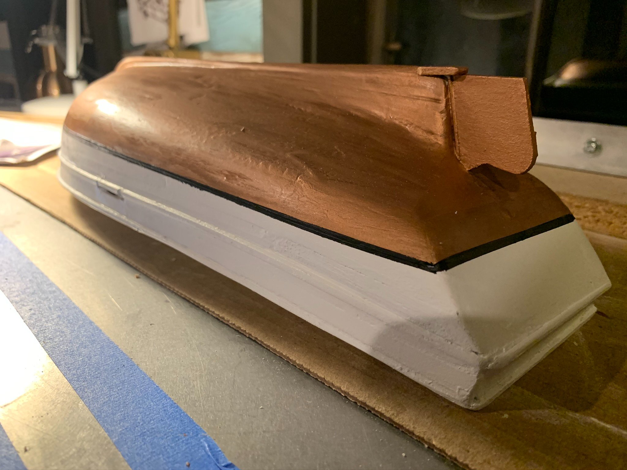
5. After some time working on the cabins, I found the copper hull paint to be dry. Seemed like a good time to start prepping for the black boottop line at water line... The instructions called for a 3/16" thick line, but I opted to go for a thinner line, so mine is 1/8". I admit I tried a few different types of tape before I settled on normal electrical tape (albeit yellow). When using the blue painters tape originally, it just didn't make the fine curves like I wanted. The electrical tape worked well, and only used the blue tape to reinforce at certain areas. NOTE: Make sure that the leading edge of the tape is REALLY stuck to the surface. I had a bubble at one area that bled through which needed to be touched up. Overall, the electrical tape did well, and the overall effect is to my satisfaction.


- Duanelaker and ThirdCoast
-
2
-
Here is some documentation on Days 9 and 10 for my "Spray" build:
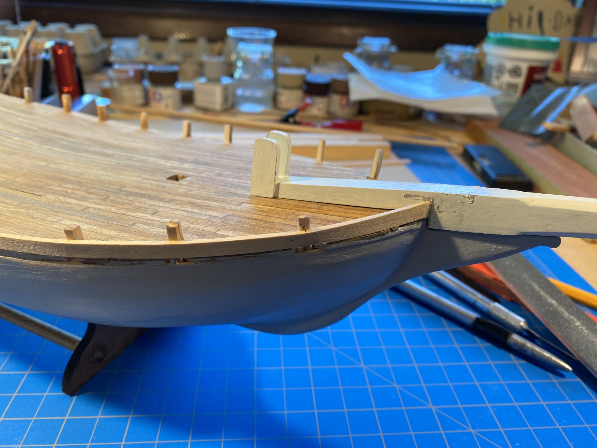
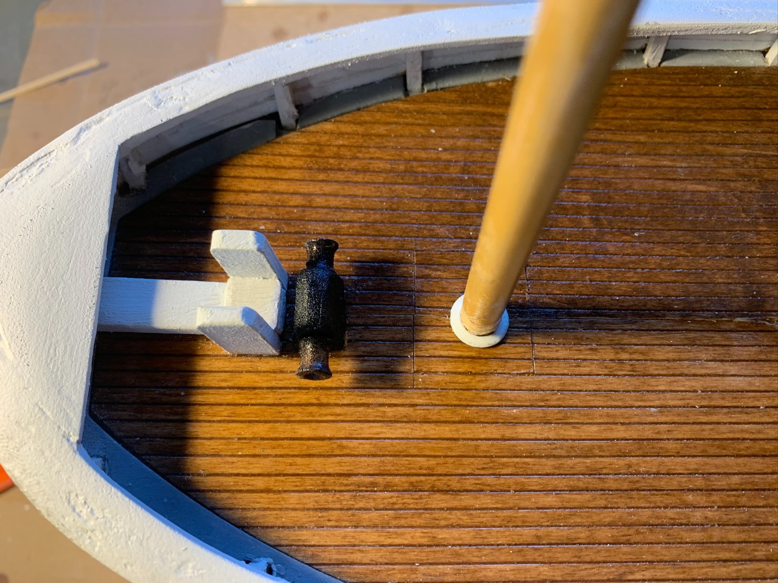
1. Fashioned the capstan and prefit just aft of the knightheads. Gave a quick coat of flat black and let dry, then glue.
NOTE: You will notice the portion of deck I removed when I had to enlarge the mast opening. These pieces I have kept safe in a little container, and I will glue them in once the mast gets seated permanently. One thing I will implement for next build will be a systematic method of storing all the small kit pieces (I am thinking something like a tackle box or pill containers. I have kept the pieces in the bag they came in, but as I open up some pouches to remove pieces, there are others that fall out. Lesson learned - will need to be more organized next time. So far, nothing lost though.


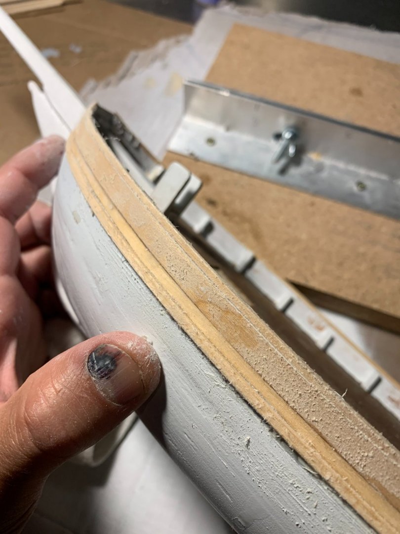
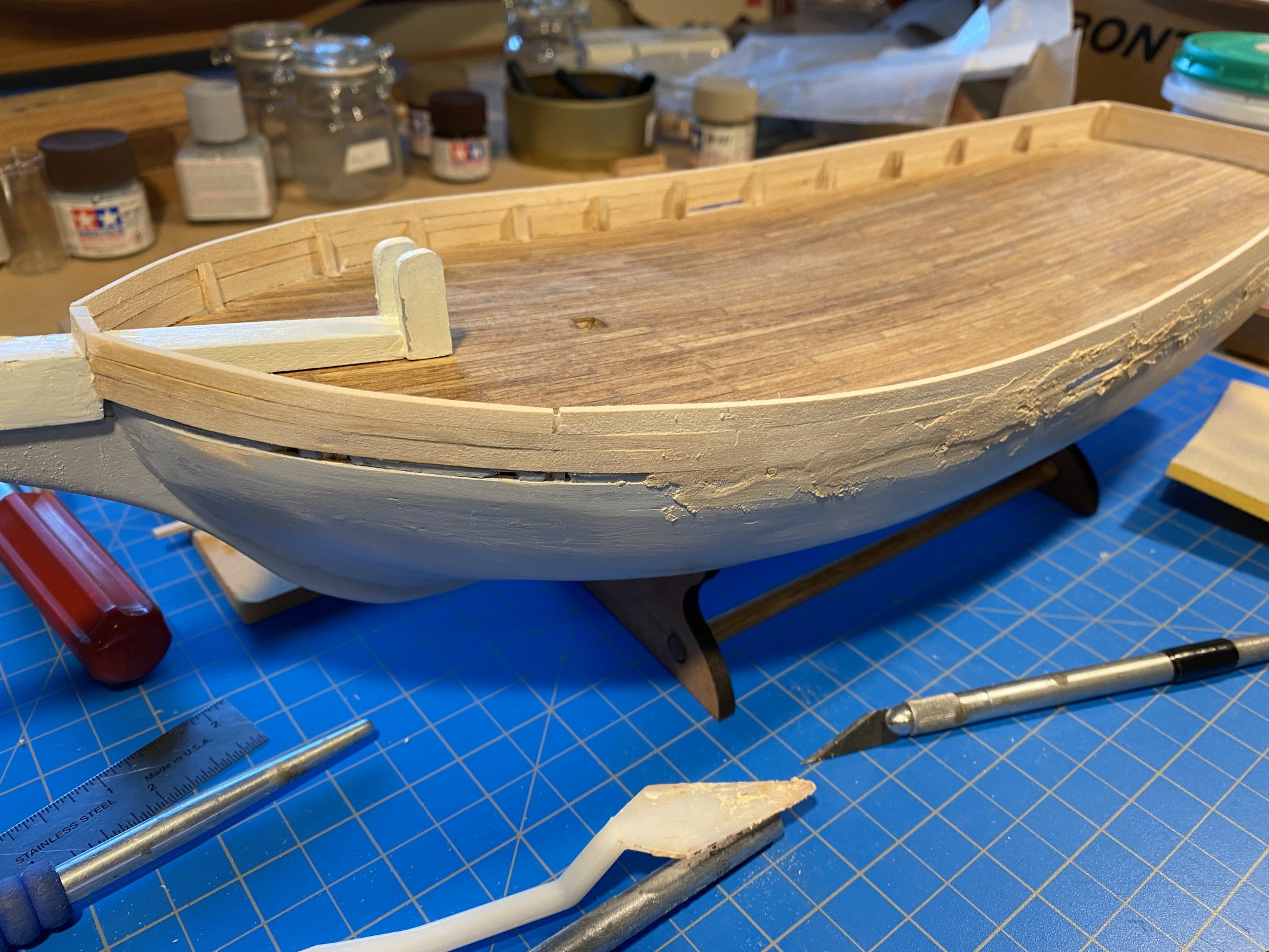
2. With the caprail and gunwales installed, I found some areas that needed to be filled and sanded a few times. Similarly, the hull required 4-5 fill/sand iterations before being sufficiently smooth. There are still some imperfections I am sure, but I do think the overall look is believable. NOTE: The rub rail extends onto the bowsprit...
This is a shorter report for today - next entry will be a little lengthier.
Until next time-
- BobG and Duanelaker
-
2
-
On 10/12/2020 at 9:09 AM, Friday Dog said:
Nice progress. Starting to look seaworthy. Have you thought of thinning your primer?
I did try this on my latest modeling day. Used some thinner with the copper hull paint specifically - and it did help quite a bit with the flow and coverage. A little bit goes a long way!
-
Hello again-
Getting caught up on some further work developments with "Spray." The below work concluded my Day #8 of working on this kit:
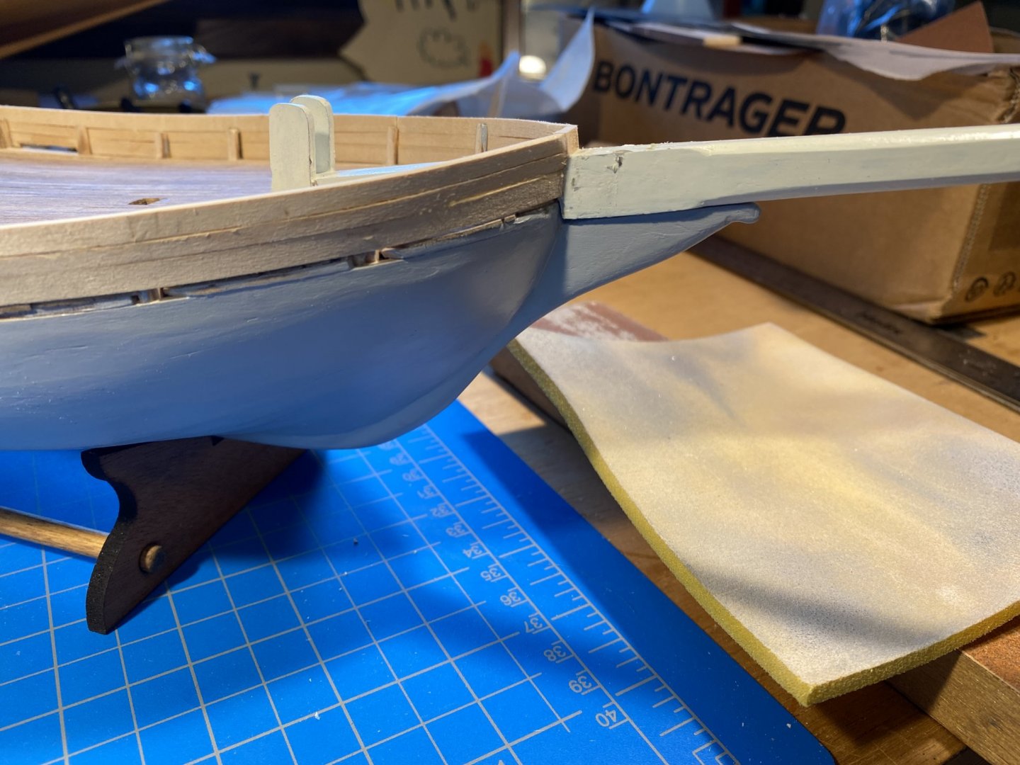
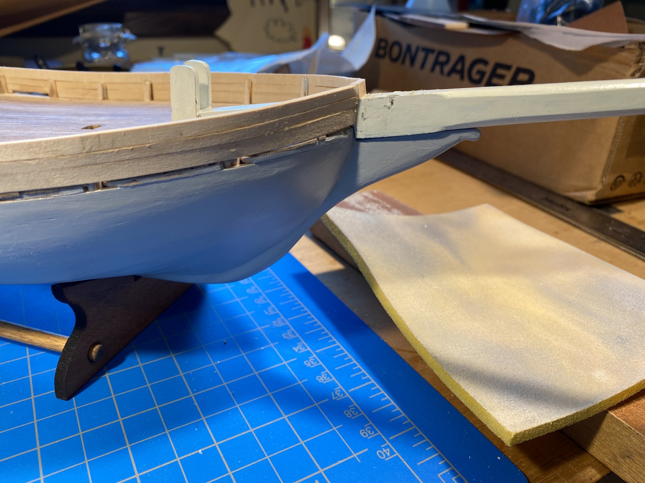
1. Where I left off prior, I had just formed the bowsprit and knightheads. After receiving their coat of flat white paint (included with the optionally purchased paints kit), those were fit and glued. ( I did check the alignment of the bowsprit with a small string down the centerline of the boat and to transom prior to gluing. Followed up with the "eyeball test" and all looked correct.)
2. Next, moving on to gunwales...
Per the section detail on plans, the vertical courses of the gunwales are made up of 1/16 x1/16" strip, followed next by 1/16 x 3/32. I seem to have somehow inverted this and now have a slightly different plank spacing... nonetheless, the overall height corresponds to the plan and I think this will be ok. the only place this mistake could be noticeable is that the scupper may be a bit taller than intended.
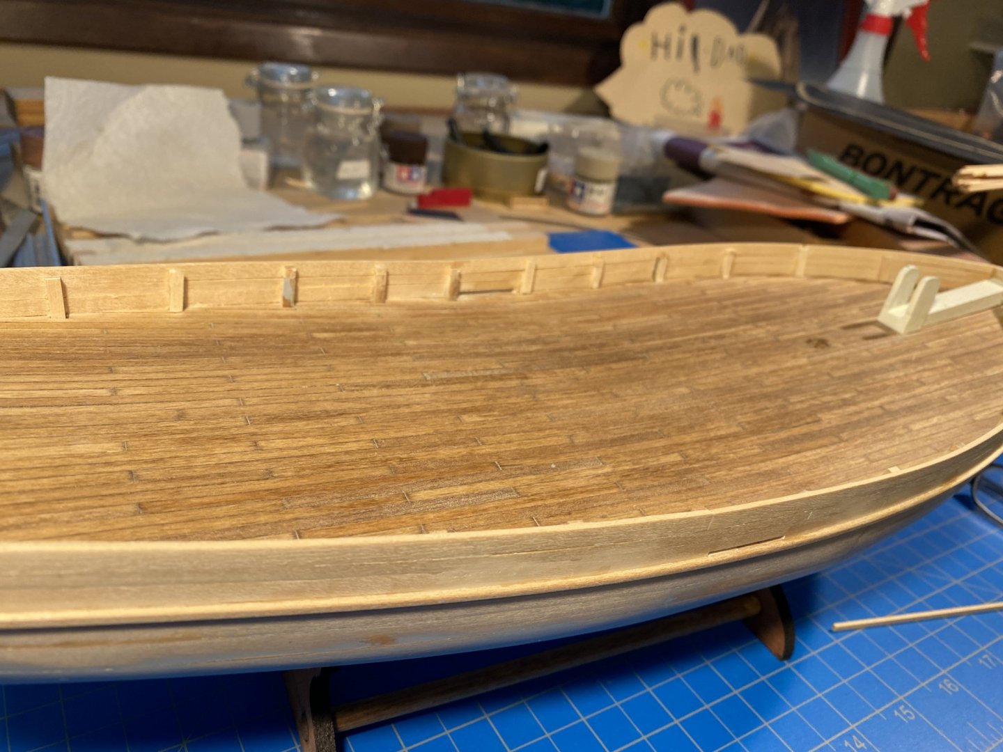
3. Moving slowly, I finally get to the rails that define the gunwale height:
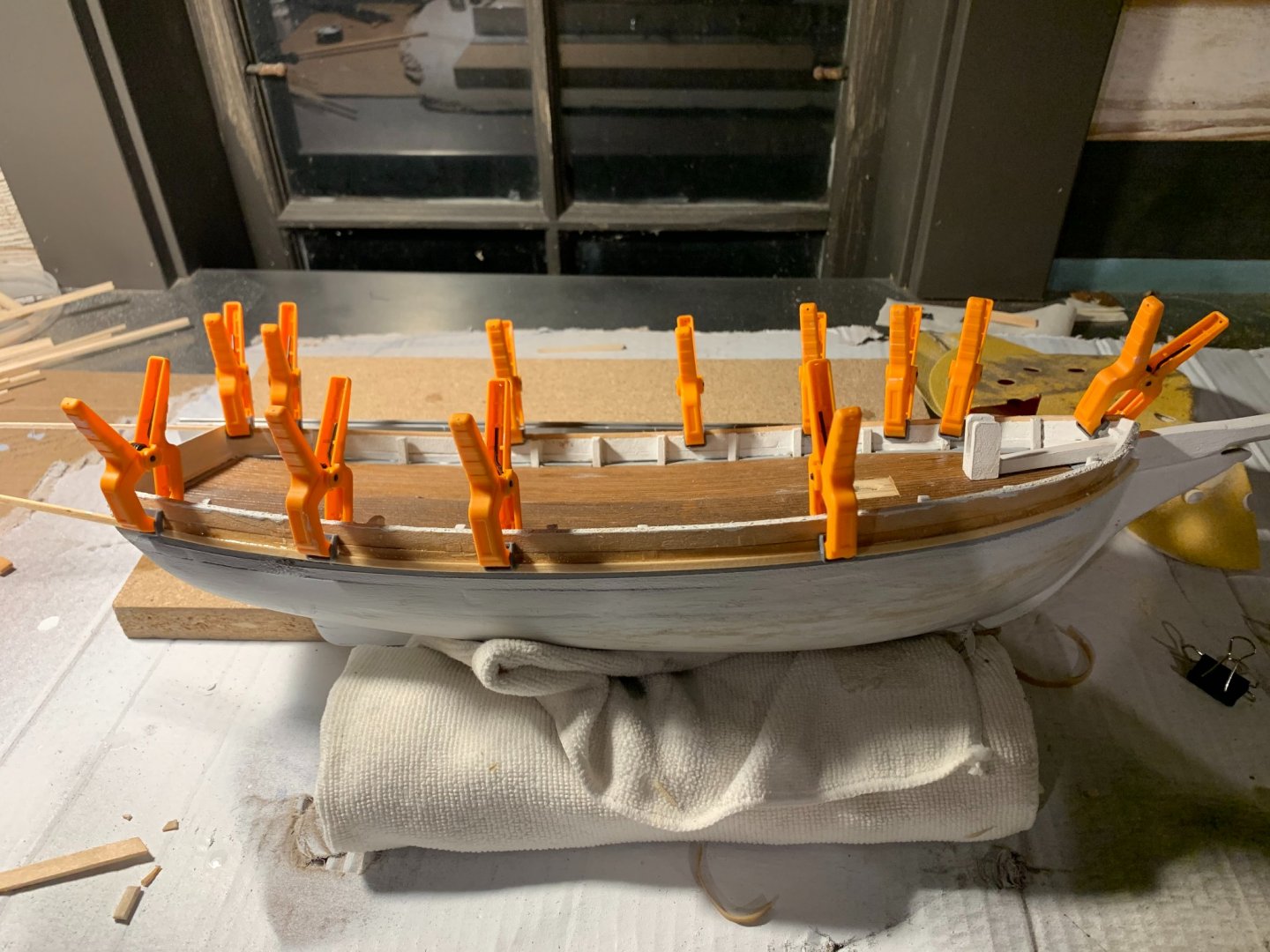
NOTE: I have sanded and filled the hull probably three times now; I have also sprayed a flat white primer in between sanding to help even out gaps, transition less-than-perfect joinery and overall give the impression of a smooth hull. While I think it needs some work yet, I think it's getting there. Perhaps it's the brushes I am using, but the brushed work is leaving visible strokes larger than I think looks believable at this scale. I am preferring the sprayed approach, and will seriously consider an airbrush for future work at this scale and smaller.
4. Further work on the top rail seen below. I will let this soaked piece set overnight, and get to the gluing of it another day.

- Duanelaker, BobG and lmagna
-
3
-
-
19 hours ago, Friday Dog said:
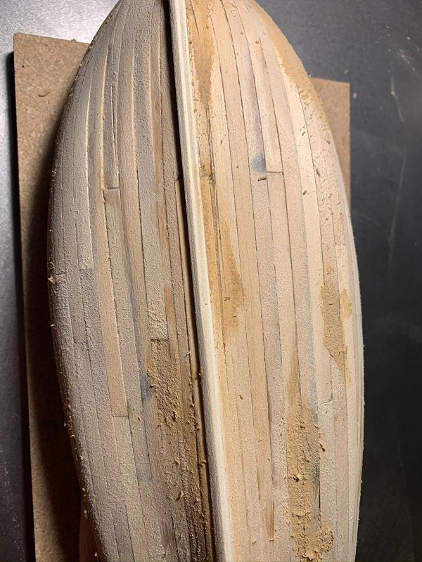
Did you try a little surface sanding on each, or is it really just a different piece of wood?
Thanks Friday Dog - this has been a fun process with lots of trial and error! I did try sanding the starboard section down a bit, but it was more about the softer grain of the piece than anything. Plus, the more sanding, the more the lasercut deck grooves start to disappear. It seems as with the pieces curing a bit more that the darker areas have lightened up. The biggest dissimilarities are at the centerline - and fortunately, the two cabins, dinghy, water barrels and steering gear will all help to cover this seam.
- Duanelaker and BobG
-
2
-
Hello again-
Getting caught up on my last couple days of build (I had some more time to dedicate to the model).
Day 6 of the "Spray" build :
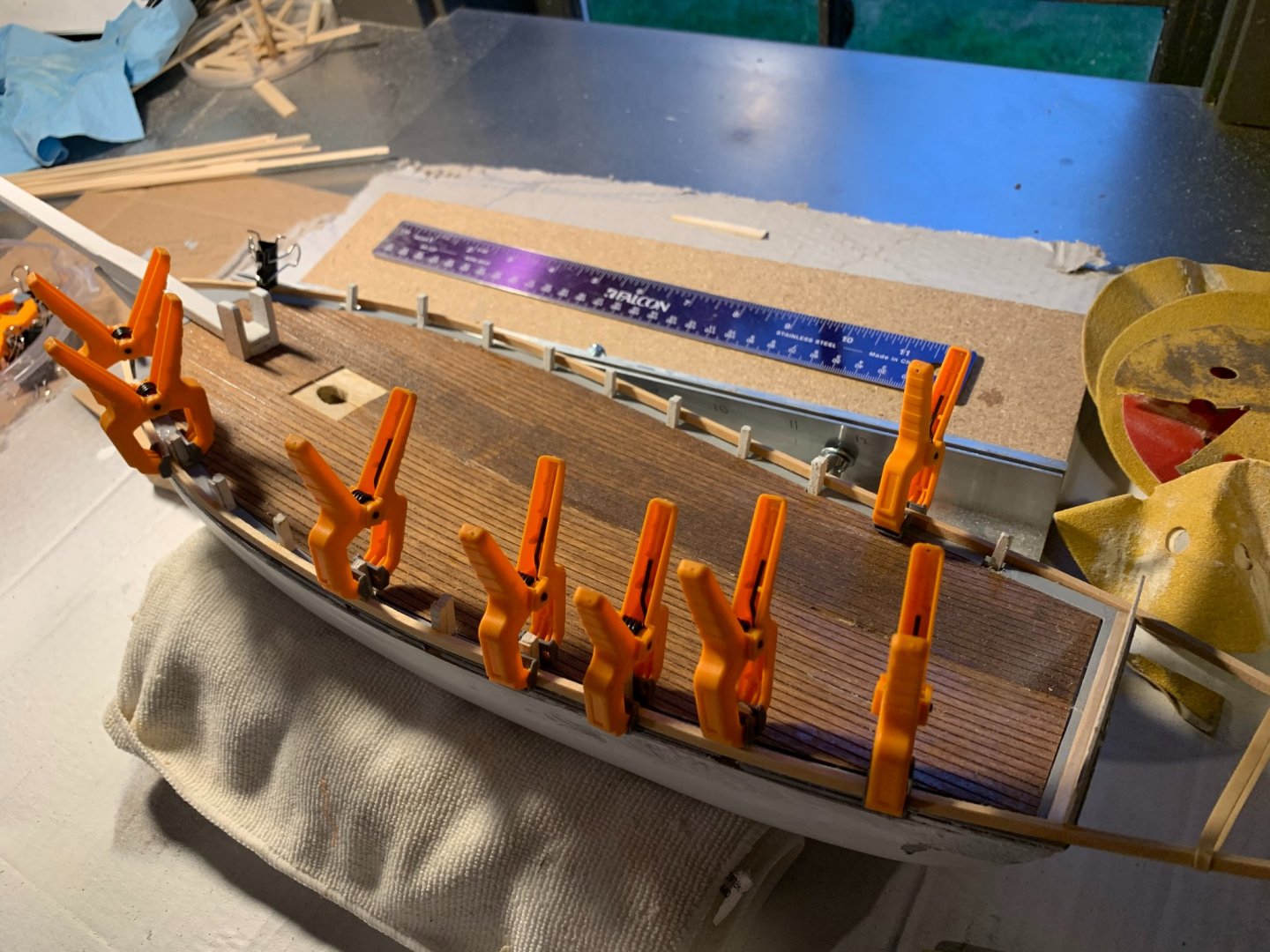
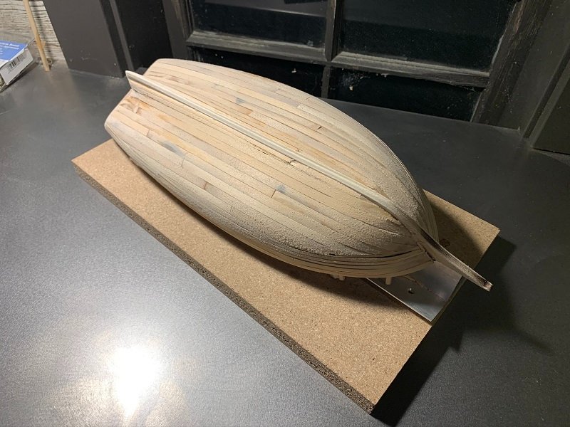
1. As described previously, I started a small plank at the keel and then proceeded to placing the wide planks midway between the bottom of keel and sheer line. This gave me a better idea about the spacing and where stealer planks would be needed. Again, using the same procedure as I did before, I would soak some planks for about an hour...start on one side, and then do the same respective piece on the other side. Prefit, clamp, set with glue, clamp, repeat... A little bit of trial and error on some sections (and I am sure there are some areas that could have been done cleaner); nonetheless I think the general shape is where it needs to be.
2. Over the course of about 4 hours, I was able to complete the hull and start examining the areas that would need more attention. I did a fairly thorough sand at 80 grit to start shaping spots where the planks edges didn't quite sit as snug to the bulkheads as wanted. I followed up with another sand at 120 grit. Mixing a bit of basswood sawdust and some Titebond wood glue, I made a putty and filled the lower areas.
At this stage, I also removed the small pieces I had near bow to assist in terminating the planking at the stem. As well, sanded and eased the keel and stem to give a more realistic shape (removing sharp edges of lasercut material).
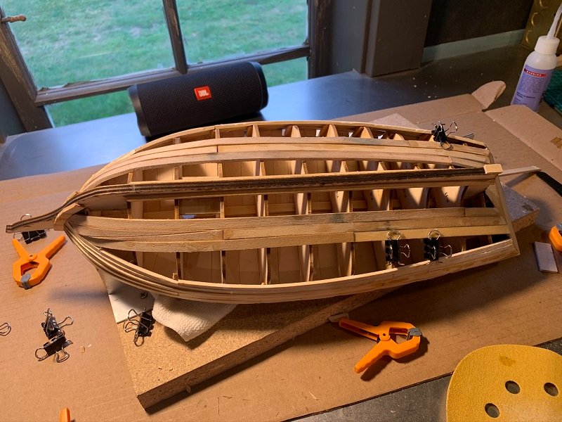
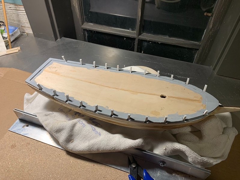
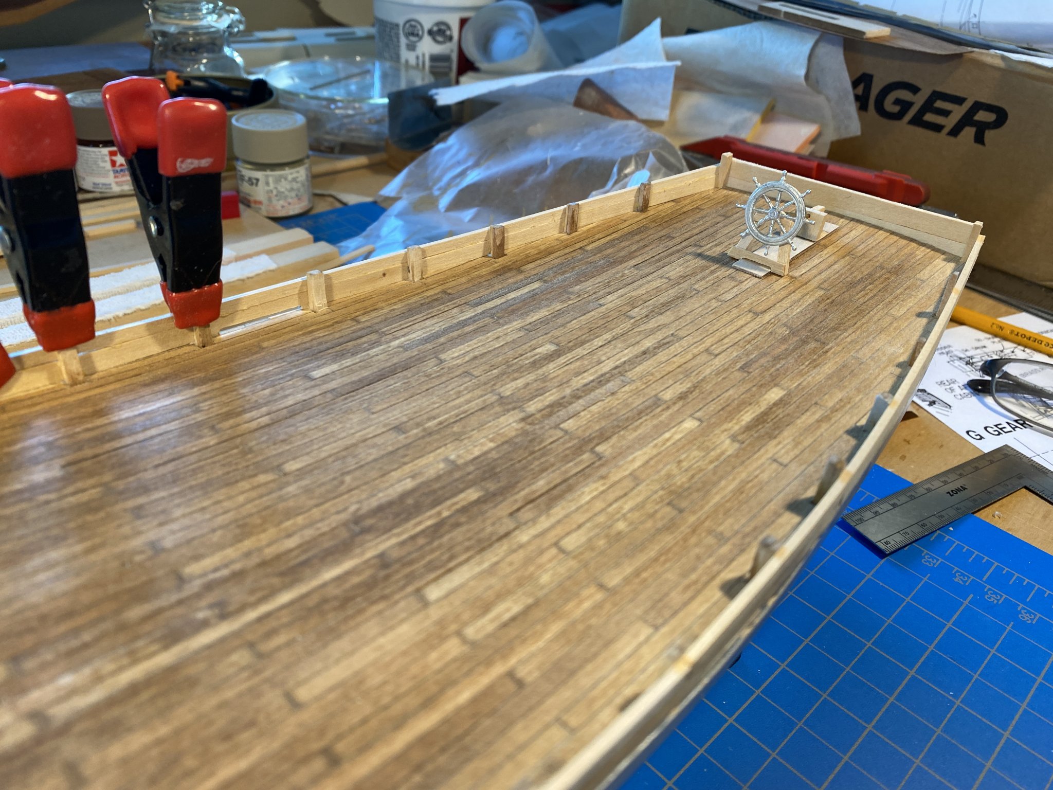
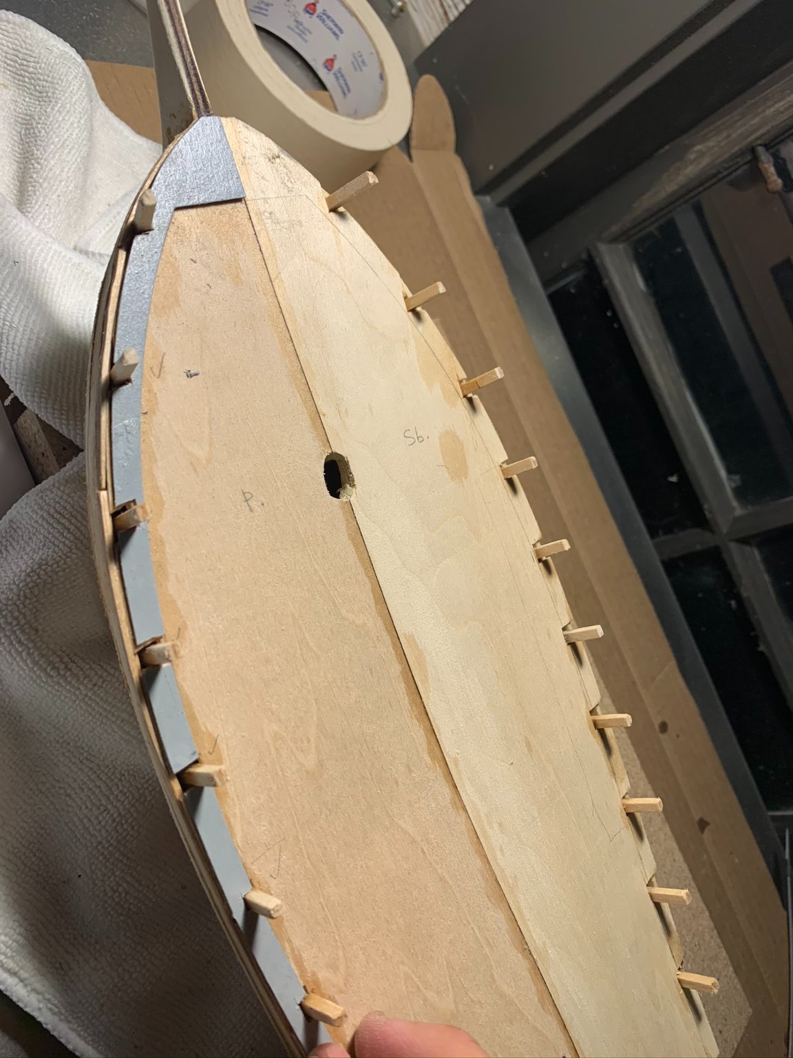
3. Allowing the wood glue to start drying, I flipped over the model and decided to put some attention towards the deck: more specifically, cutting and affixing the margin planking and pre-fitting the lasercut decking material.
NOTE: On placing the mast, I found that the location of the mast step as that transferred from the plan, as well as the corresponding hole cut out in deck plan, resulted in an overall lean forward to the mast. I measured and determined I needed to enlarge the hole towards aft, and then glue a little wedge to keep the mast at the correct "slight lean towards aft" position. Knowing that the finished deck will cover up the larger-than-needed hole, I decided this wouldn't be an issue. Nevertheless, you will see that the hole in subdeck is a bit larger and elongated than what would be ideal.

4. The location of the stanchions I found were generally too far inboard so as not to allow for a continuous margin plank as designed (see above and below images). I can see one more reason now as to adhere to the model instructions on installing the stanchions post-subdeck install. But moving along, I carefully cut the margin plank as tightly as I could.
NOTE: Before gluing the margin plank down, I decided it would be a good idea to paint the stanchions white (thinking it would be progressively more difficult to access them as the finished decking and bulwarks assembly get installed). Additionally, I chose to paint the grey primer on and around the margin plank areas so that any areas either showing between the plank (or where deck meets margin may not be perfect), there would not be raw basswood.
5. I pre-fit the finished deck material and had to make some very small trimmings to the aft side and the adjoining edge down the center (noting more than 1/32" of an inch.
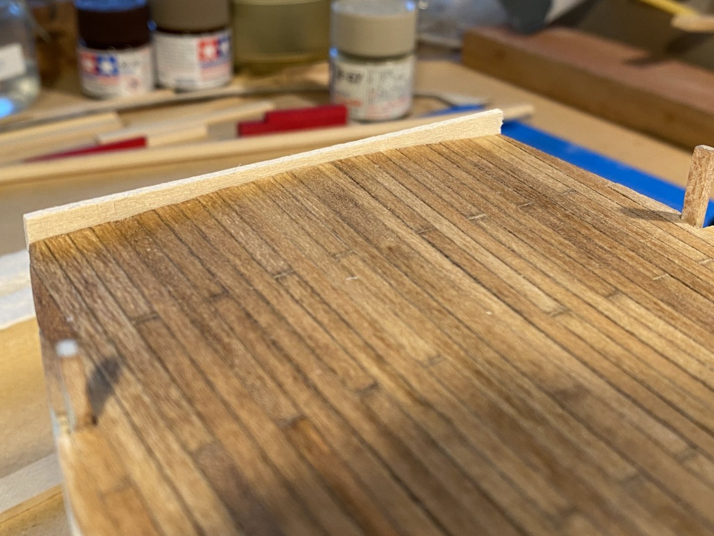
I chose to stain the deck with a Varathane penetrating wood stain "Early American." After that dried, I followed up with a coat of urethane spar varnish.
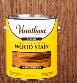
NOTE: One thing I noticed was that the two deck pieces are cut from different basswood sheets, and the starboard section has taken the stain much differently that the port side. You will see in the below picture that there is some blotchiness near the mid sections of the starboard deck. I am hoping that with the cabins and other deck accoutrements installed, this will be less noticeable. The port section, however, looks great in my opinion. (I am still deciding on whether I want to put a grey putty in the deck seams as the instructions would have me do. I have some time to decide on that as I will be painting the hull first before installing decking).
6. Lastly, I did some color tests with the kit-provided options, and there wasn't one that I much liked. Instead, I decided that what looked best was a Minwax Natural 209 (something I already had). I believe I will use this and a coat of urethane spar varnish for all spars and masts.
NOTE: You will see below the little wedge I needed to install to set the mast at the proper rake aft as mentioned above in Number 3.
That's a wrap on a long day!
- BobG, lmagna, Friday Dog and 1 other
-
4


Spray by HIPEXEC - FINISHED - Joshua Slocum's Sloop
in - Build logs for subjects built 1901 - Present Day
Posted
Nice work Rich! Really enjoying seeing this come together.
-Josh