Supplies of the Ship Modeler's Handbook are running out. Get your copy NOW before they are gone! Click on photo to order.
×

Mike_H
-
Posts
240 -
Joined
-
Last visited
Content Type
Profiles
Forums
Gallery
Events
Everything posted by Mike_H
-
Thanks - I’m sure all my stylistic details are copied from others - so copy all you like.
- 109 replies
-
- 1
-

-
- snake
- caldercraft
- (and 1 more)
-
You seem to be going great guns. Keep it up! Mike
-
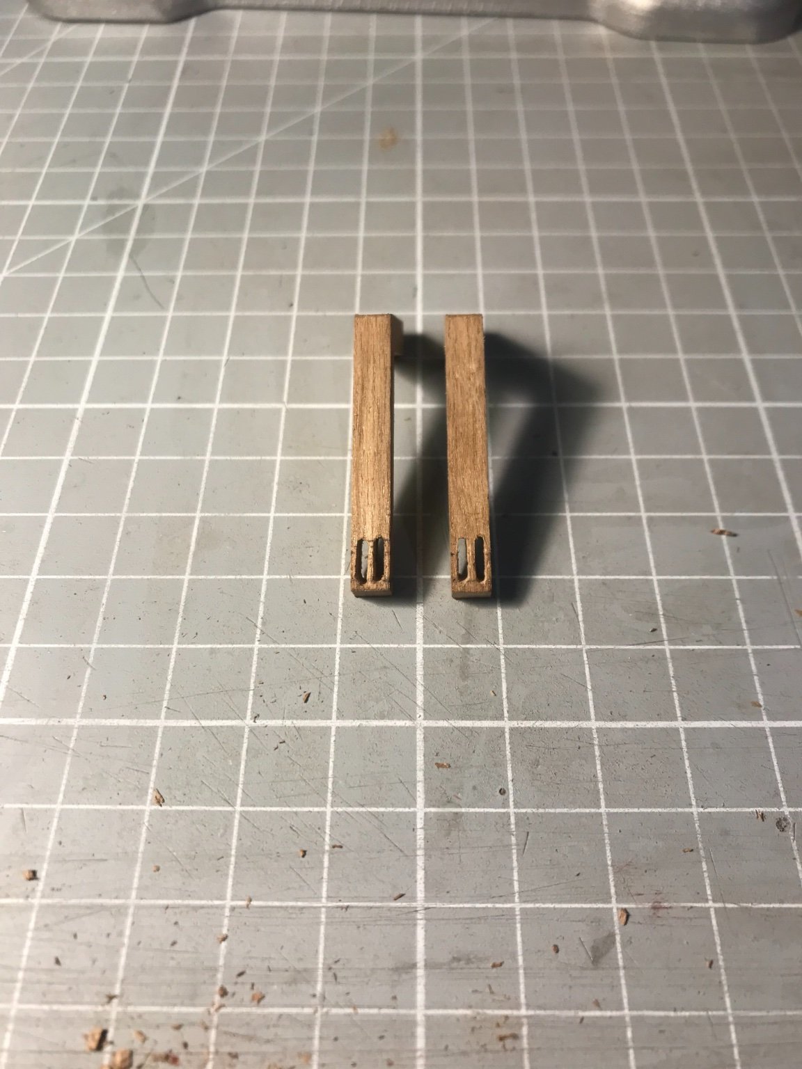
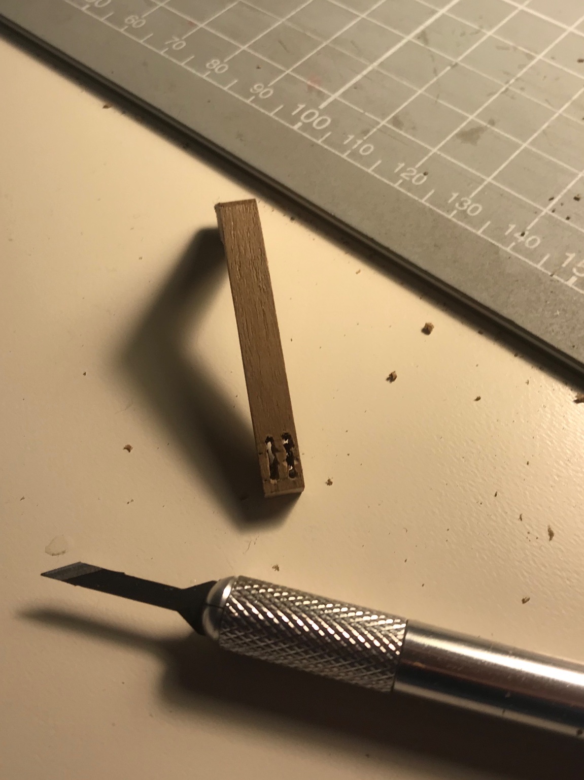
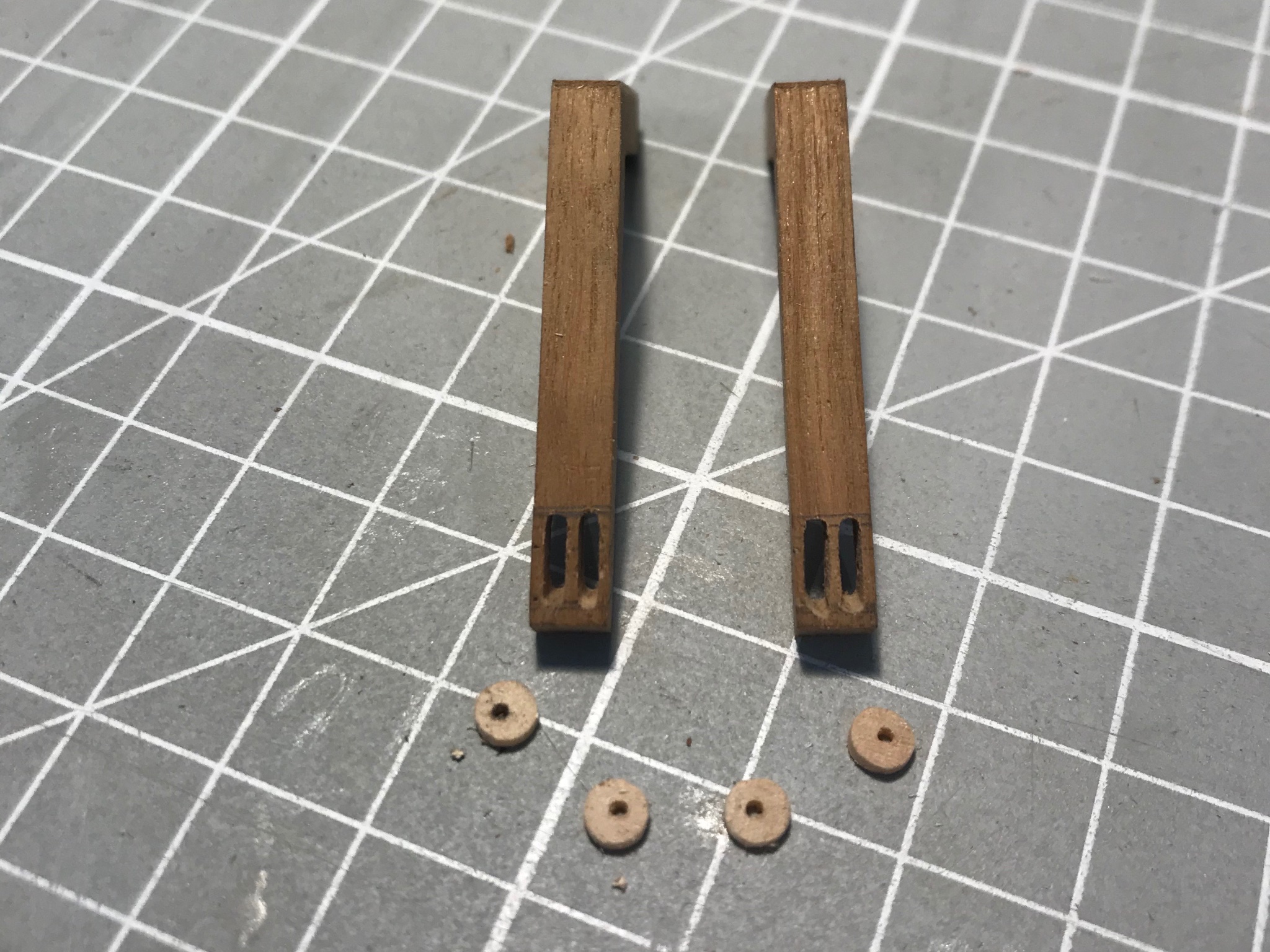
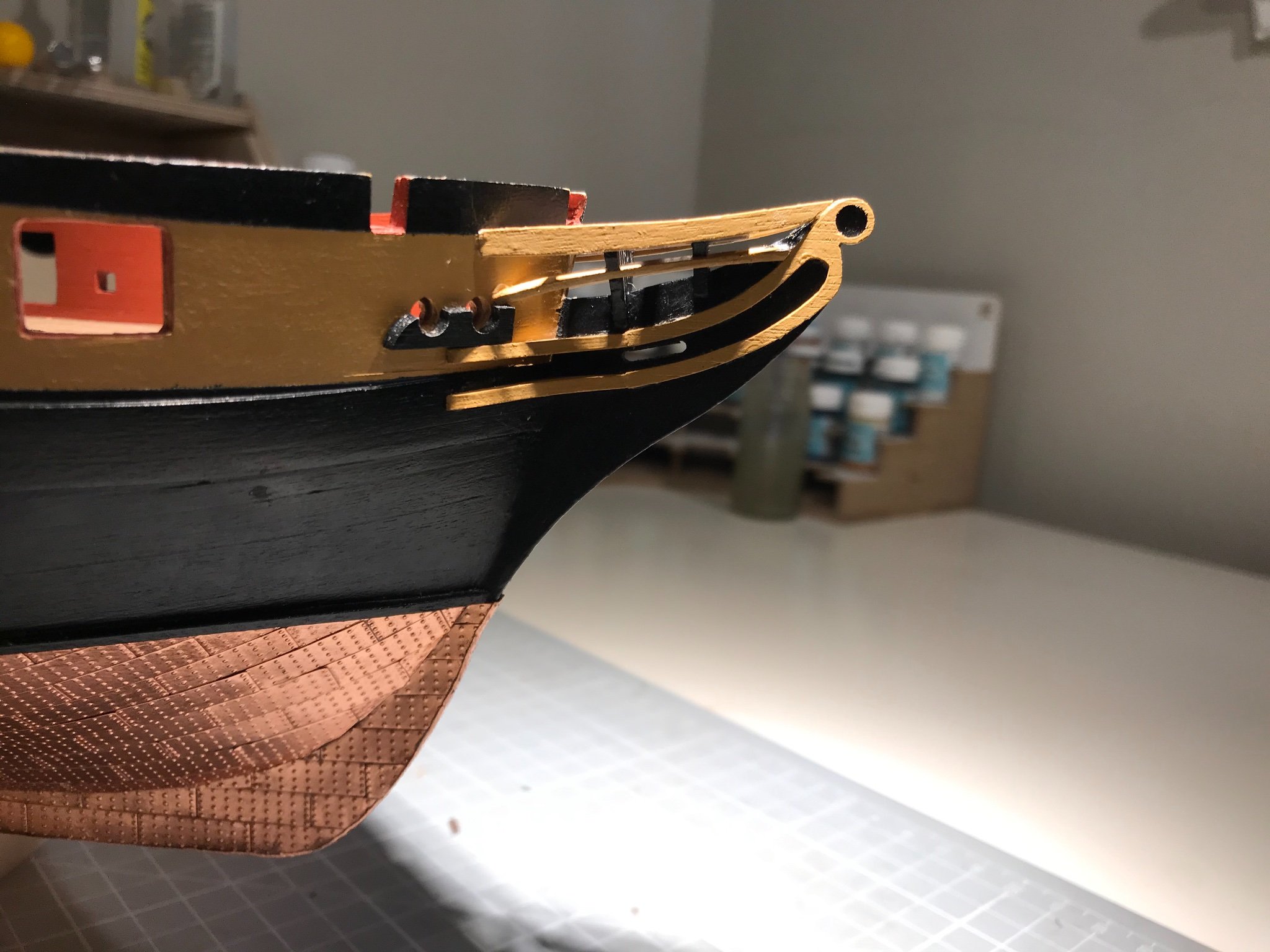
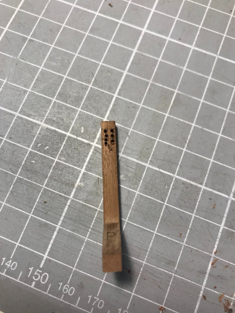
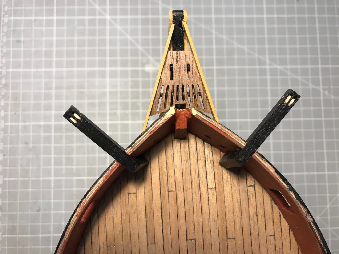
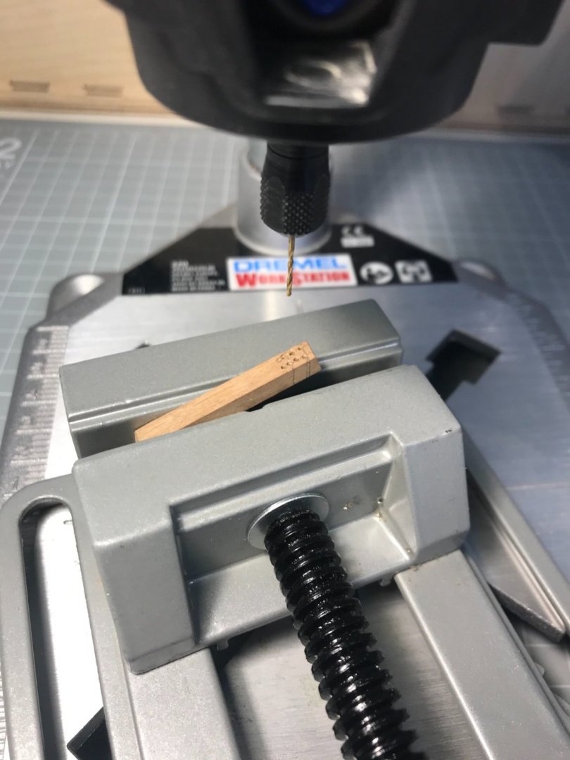
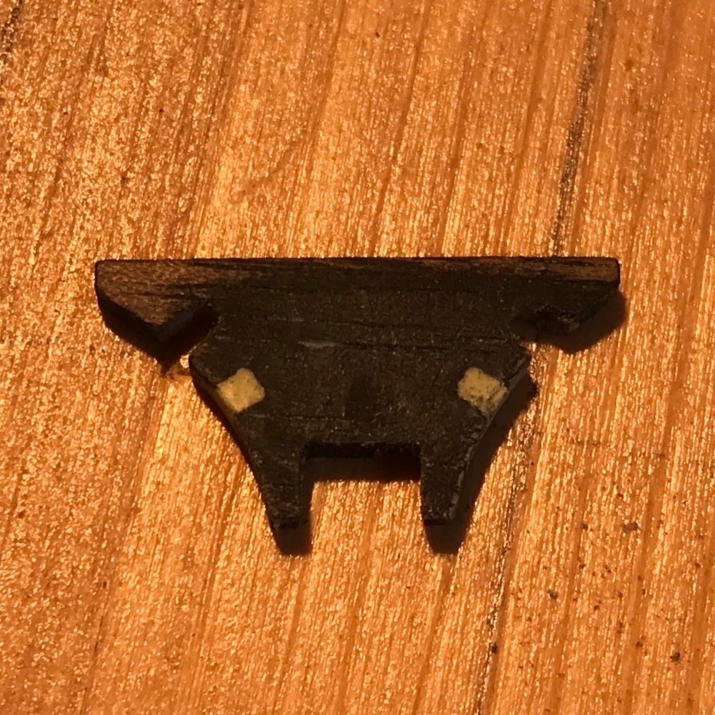
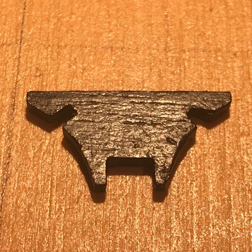
And here are the catheads. For the first time I embellished the kit design: rather than just drilling four holes where the catfall would run through the sheaves, I drilled-out and then-chiselled out slots into which I could fit some sheaves. Holes drilled at an appropriate angle to be vertical when installed. Reverse side shows that the dremel is only a fair drill press Best description is probably gouge-, not chisel-out the slots. Here they are with 1 mm discs cut from 3 mm dowel. Centering the holes in the discs proved beyond me. A trial fit using two pins (nails) seems to look ok And the finished product now pinned in place with 1 mm brass rod Quite a lot of fun!


- 109 replies
-
- 8
-
-
- snake
- caldercraft
- (and 1 more)
-
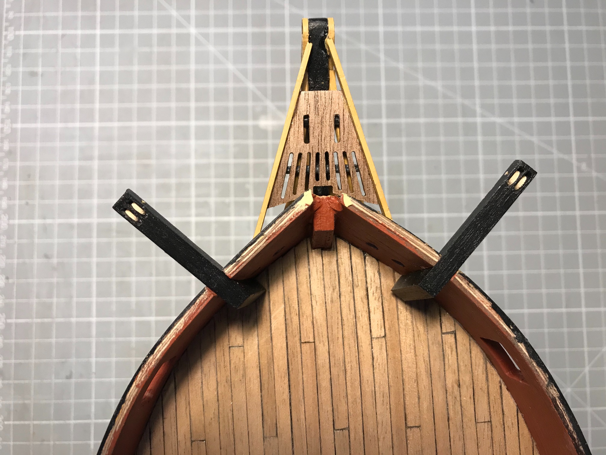
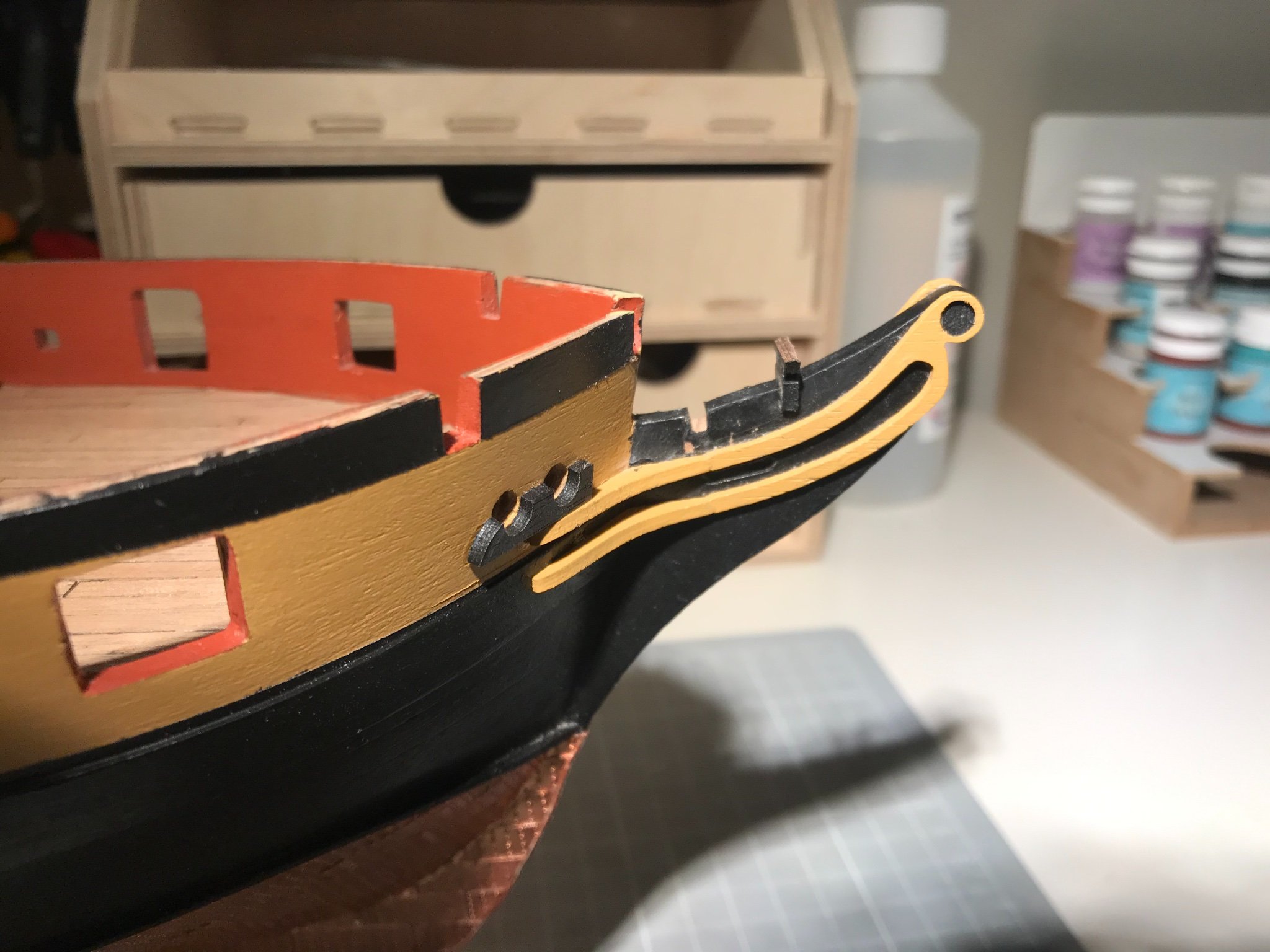
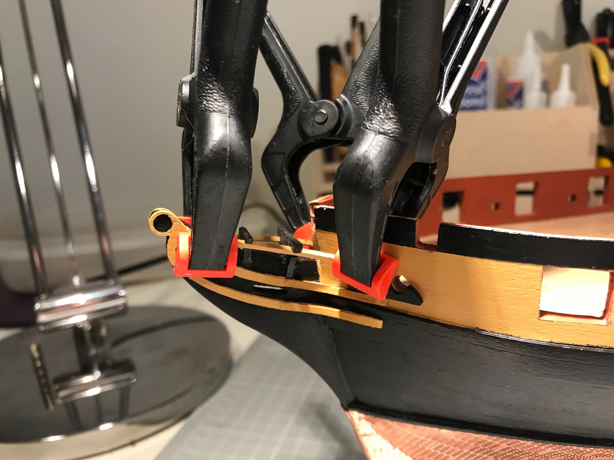
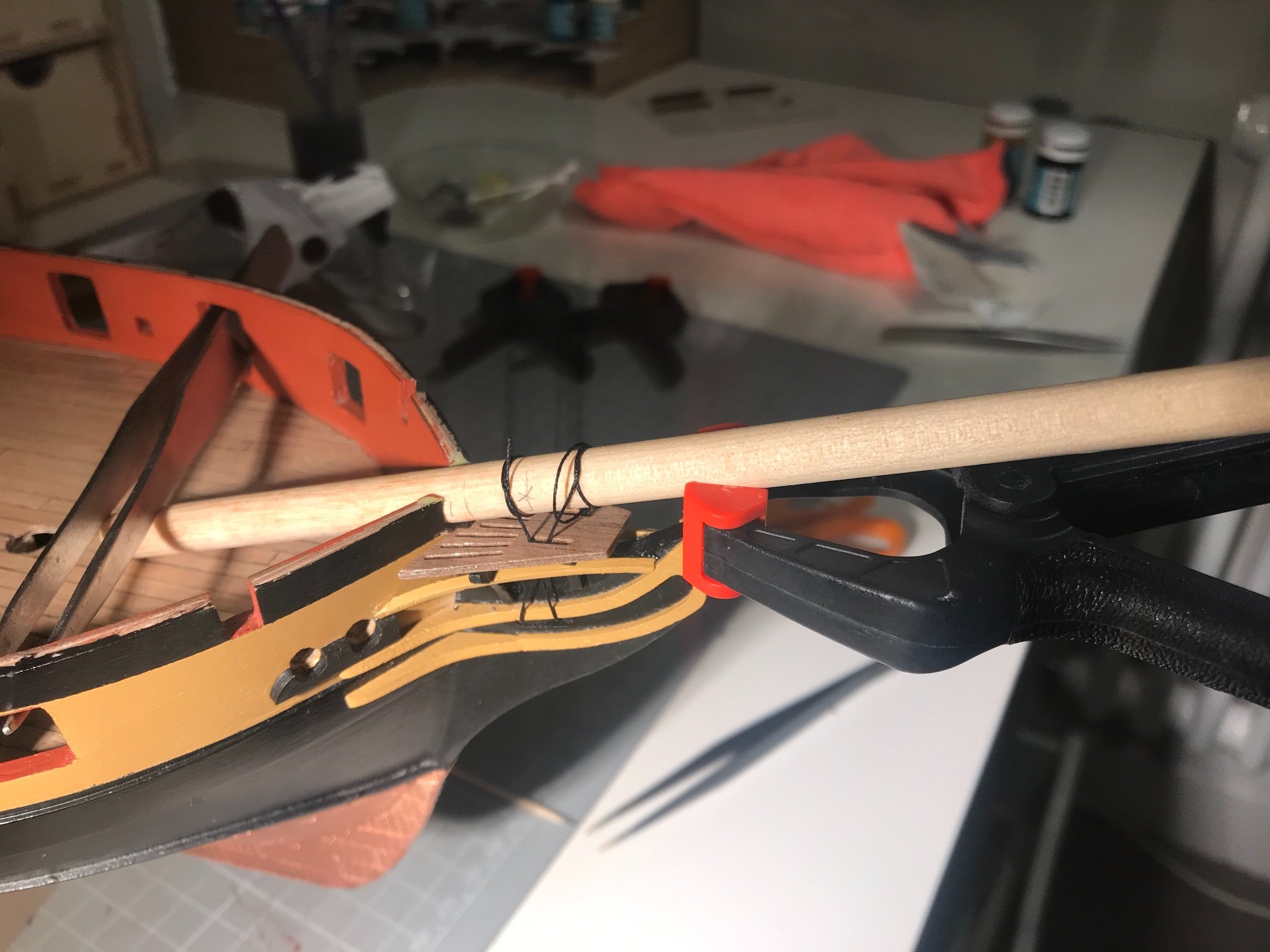
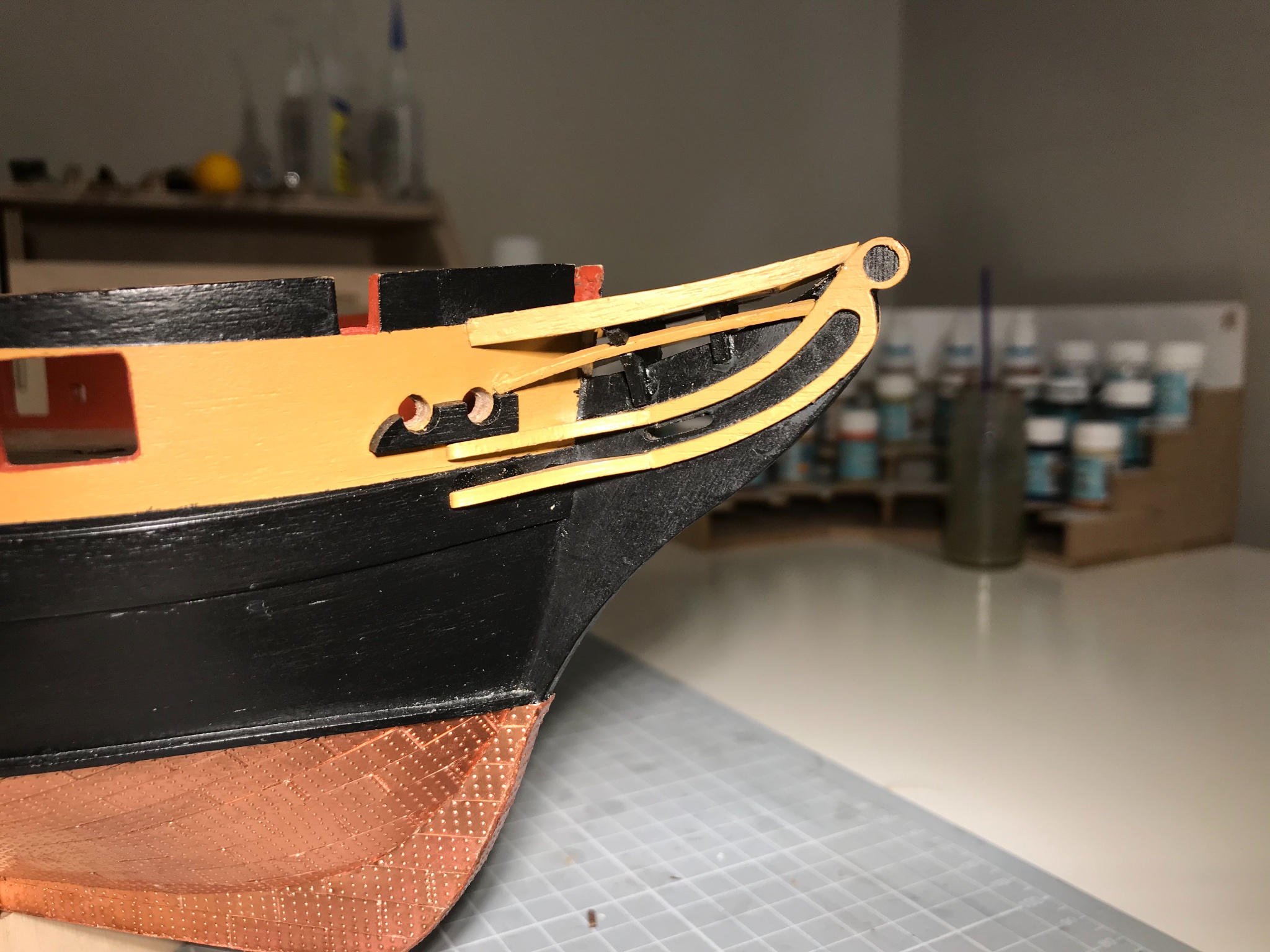
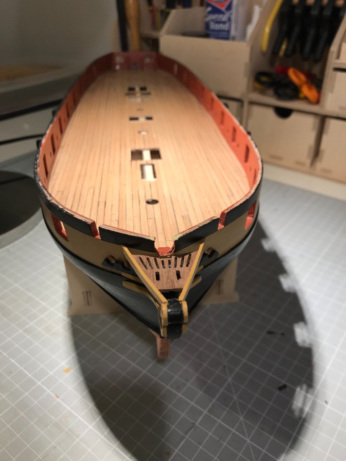
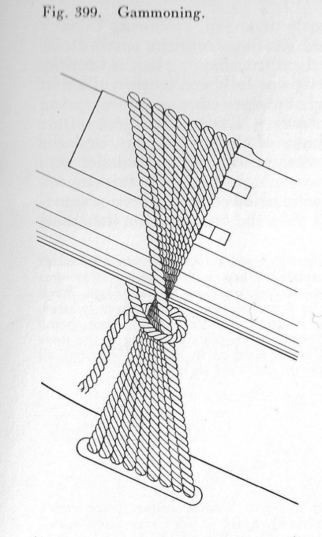
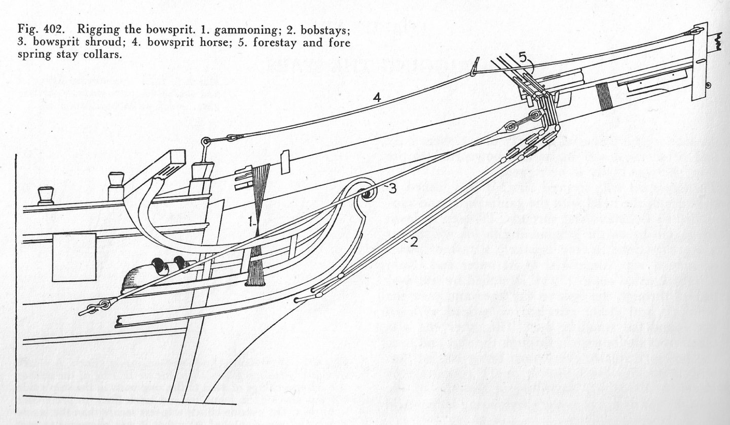
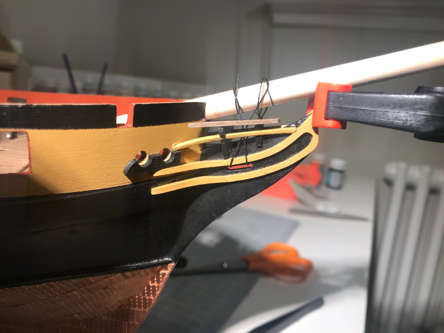
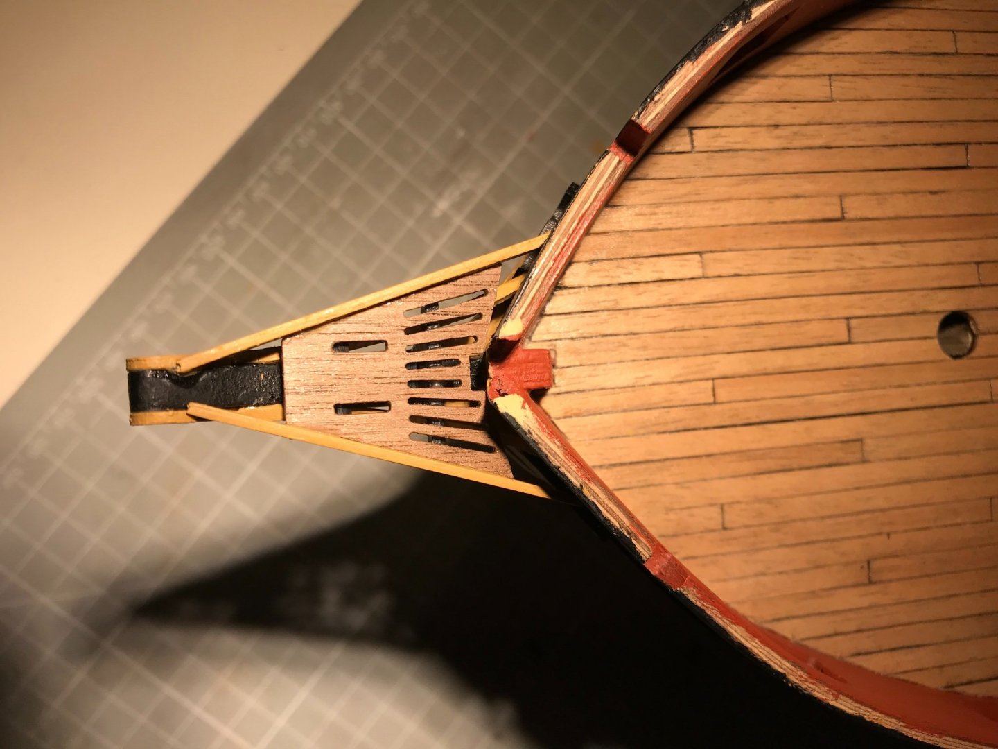
Headworks done. Not trivial as the provided parts and drawings are what a draftsman wold describe as being of nominal scale. Once you work that out, and engage low gear and defensive driving mode, it was all quit pleasing. The bow rails and cheeks go on first, and take quite a lot of sanding (cheeks) and trimming to length (rails) before all is good. Next comes the "bow head rail frames", or grating supports, as might be said with fewer words. Easy enough to paint and glue, at which point it is apparent that the grating sits much too high (wish I had re-read @Beef Wellington before I glued). The fore support was firmly glued in place so I just took a saw to it, and chopped the top off. For the aft support, I could prise it off, and then filed-out the slot as deep as would allow the support to fit above the bow rail. Photographed it at that point: That meant that the lower rail slots in the aft support were not in the right place - so I "moved" them, filling the old slots with milliput, sanding down and filing new slots, and then painting, again. Not the RH slot has been eased slightly to allow the rail to rotate With that, the supports could be glued again and the lower rails added. I used thick CA, but the rails needed a little persuasion to adopt the right position, so needed clamping while the glue set. Now, the next job is to fit the grating, but as many have discovered before me, the slots in the grating and in the knee of the head, for the gammoning, do not aline, at all. BUT Petrejus says they shouldn't, because the gammoning is not simply would around the bowsprit and through the slots. Instead they cross over to create an "hour-glass' shape. (Steele say the same, too) I bit of fiddling with a dummy bowsprit and a bit of thread shows that all is good! Upper rails to install and then we are done! (naturally I had a glue nightmare at this point, but deep breath, clean it up, all's good) Quite a lot of fun, really, and IRL it looks good. In these photos you can see that the paint has taken a bit of a hammering, and the glue is not as neat as some manage. I used gloss varnish on the grating, which I think looks great. It should be said that this really was a painstaking process, as a great deal of dry fitting is needed, but you cannot do that for a part until the previous parts are glued and secure. It's a case of gradually trim and sand to shape, paint, wait, glue, wait, repeat six times, on both bows. Fun though, as I say. Catheads next.


- 109 replies
-
- 6
-
-
- snake
- caldercraft
- (and 1 more)
-
Hi Sjors Thanks for the comment. I’m not quite sure what you mean by separate the the paint with the copperplates. If the paint you are referring to is the black-painted hull, then the separation is by a “waterline batten”. In my case a 2x2 mm walnut strip. But if it’s something else do ask. I guess English isn’t your first language but I know from experience that the Dutch are very good at making themselves understood in half a dozen languages. By the way, my experience of the Dutch was from very near you, I think. I spent a lot of time in Delft and unless I’m mistaken Bleiswijk is nearby. In fact I think I rode my bike through there. If I’m right - small world! Mike
-
Looks sweet, Sjors. I’ll have to keep moving or you’ll catch me! Mike
- 53 replies
-
- 2
-
-
- brig-sloop
- Caldercraft
- (and 2 more)
-
That is some tease, James. I wonder if @chris watton remembers the conversation and the thought...
-
Cheers! I think the real lesson is the more you do, the better you get - so your Snake will be a beauty.
-
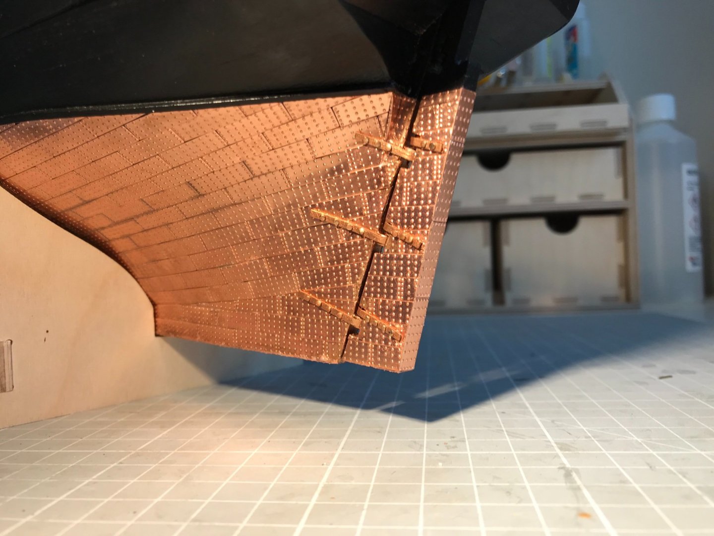
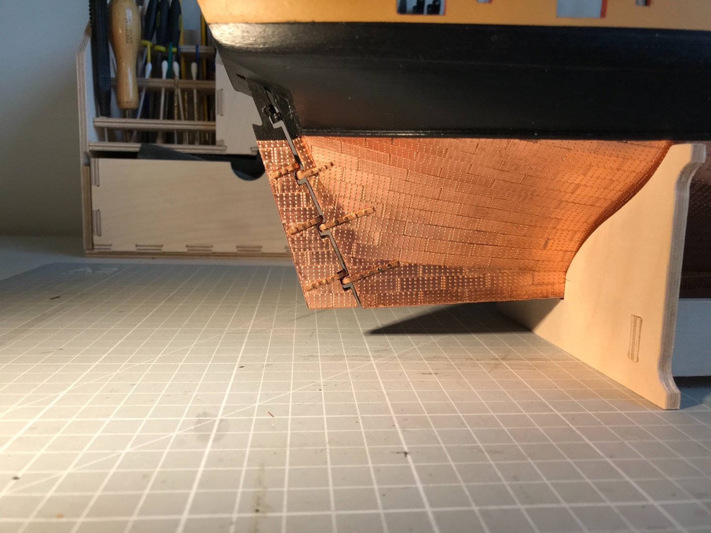
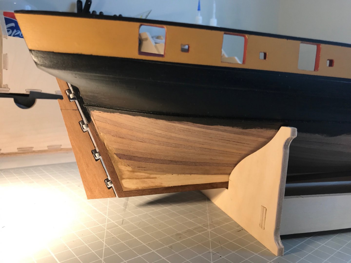
The straps on the gudgeon and pintles (you can never use those words too ofter) are done, and with it everything to do with copper is completed. I'm happy with the outcome, but I must say I found it more frustrating than expected. I attempted to followed Jason's, @Beef Wellington, workflow of: bend strap around a dowel, glue at the bend onto the gudgeon/pintle, drill for a trimmed nail and attach the strap square to the stern-post. In fact I did this on the rudder and I rather messed it up as the glue was remarkably reluctant to bond. This arose because I had pre-painted the straps with undercoat and two coats of copper, and between them adhesion was not strong enough. On the hull I marked a pencil line square to the sternpost held the strap in place and then marked for drilling at the extreme hole. I trimmed a nail to about 3 mm long, and then inserted. The nail were leftover from my Artesania Latina build as they had round, un-countersunk heads. A 0.7 mm hole gave a slight interference fit with the nail, so no glue was needed. I then did the extreme hole on the reverse side. Drilling and nailing the other holes then completed the strap. The concave nature of the hull naturally pulled the strap tight around the pintle. Getting the nail heads to sit flat was a struggle and I wasn't willing to brute force them (given my experience with fitting the false deck all those months ago). I also don't much like the paint finish. In retrospect I certainly wouldn't add the the copper paint before attaching. So as in everything to do with this project, I reckon I know a lot more at the end of task than at the beginning. And here are the results of that journey: What next? Bow rails I think.
- 109 replies
-
- 6
-
-
- snake
- caldercraft
- (and 1 more)
-
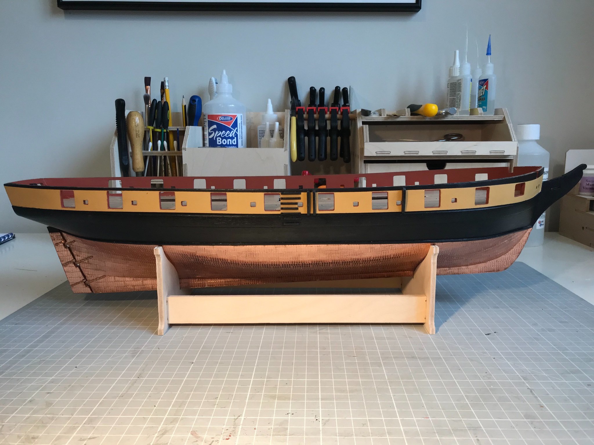
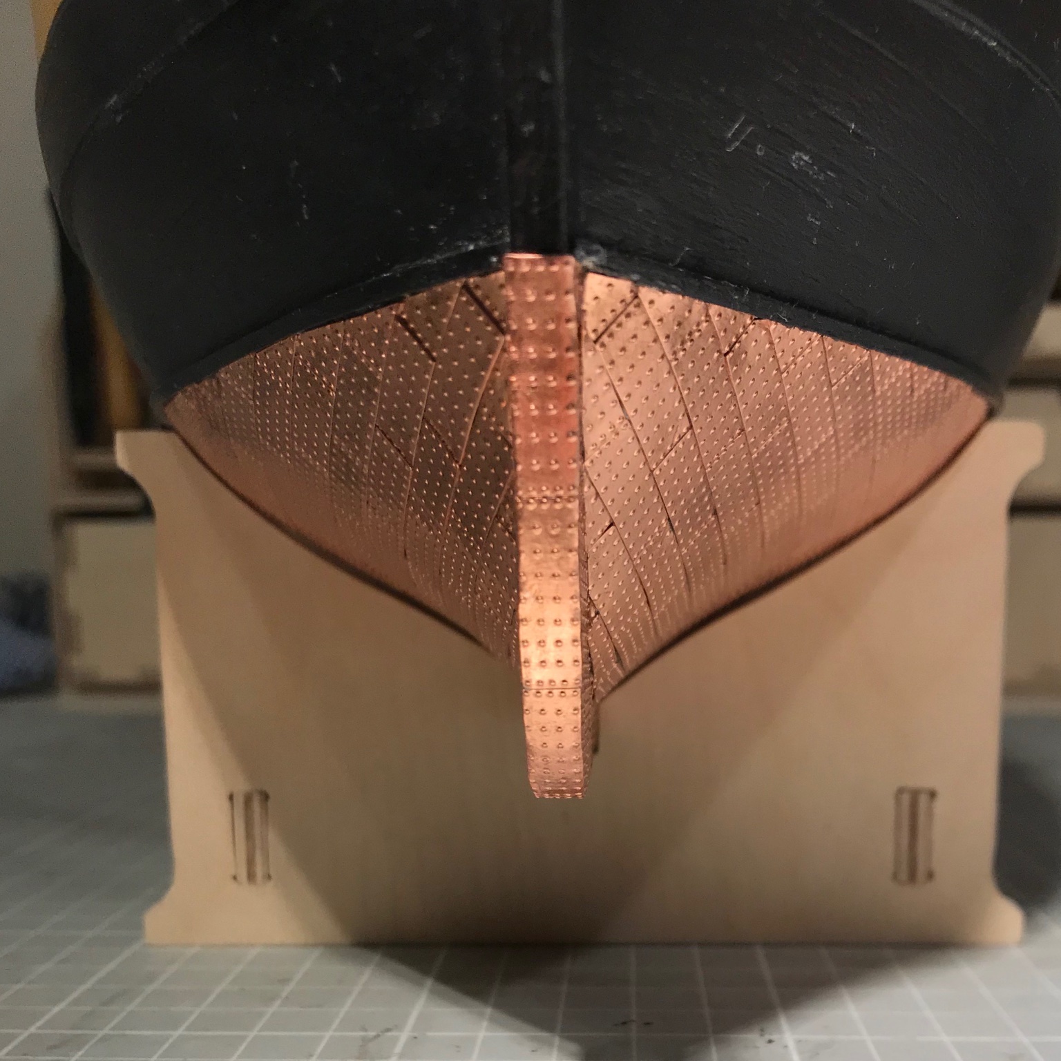
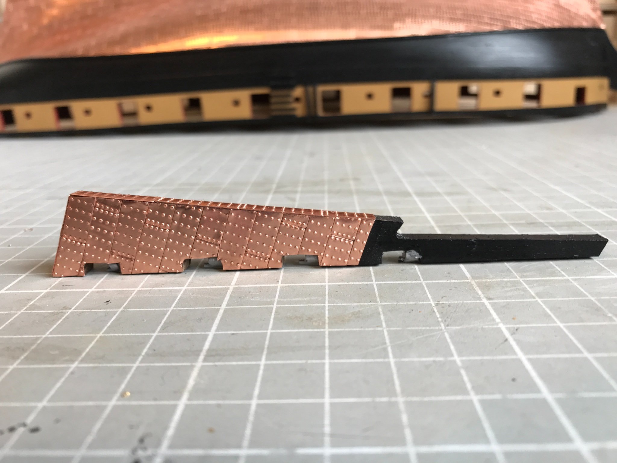
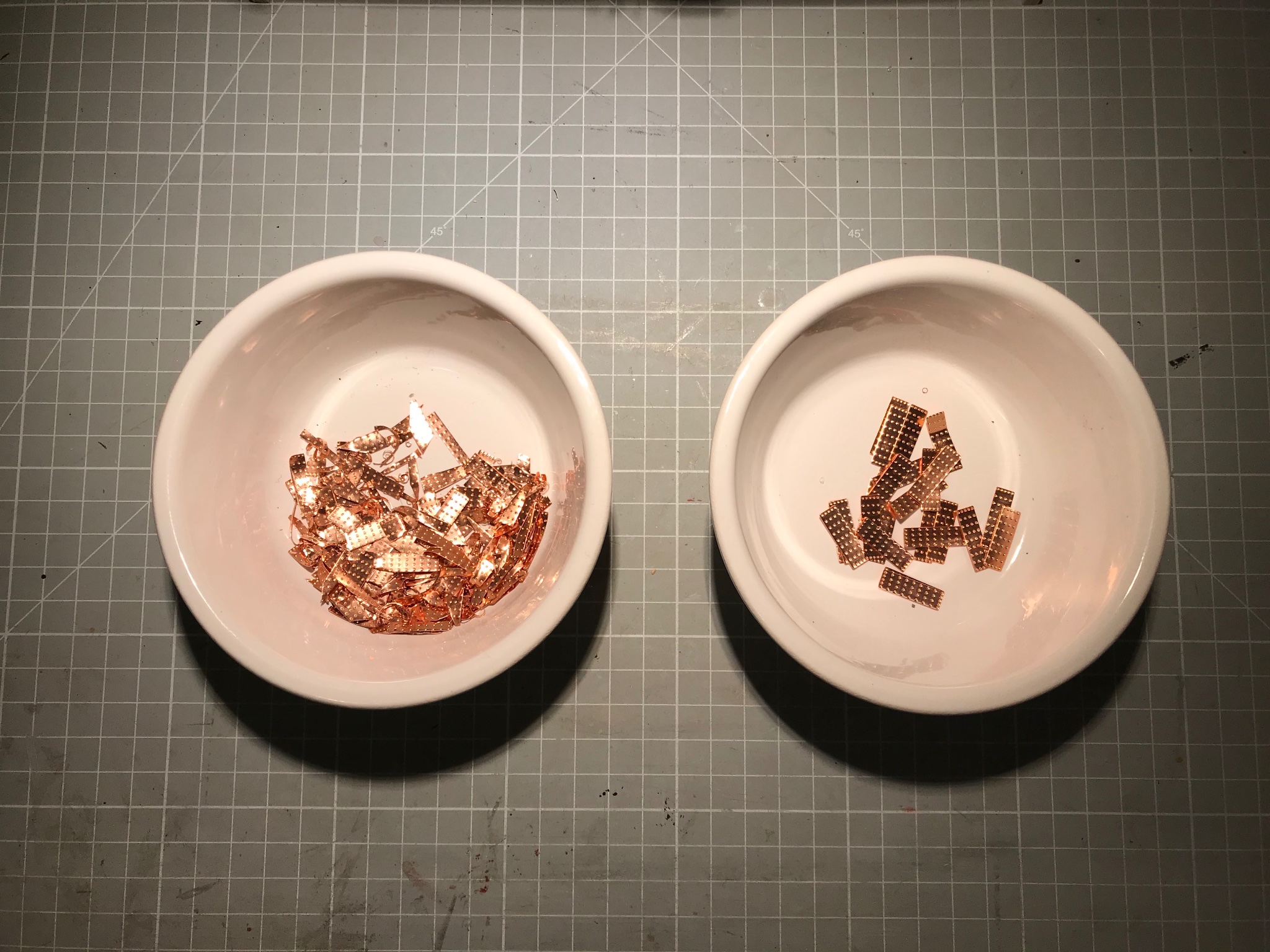
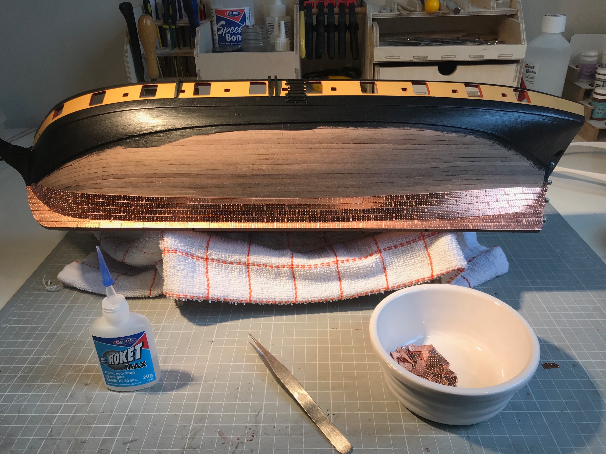
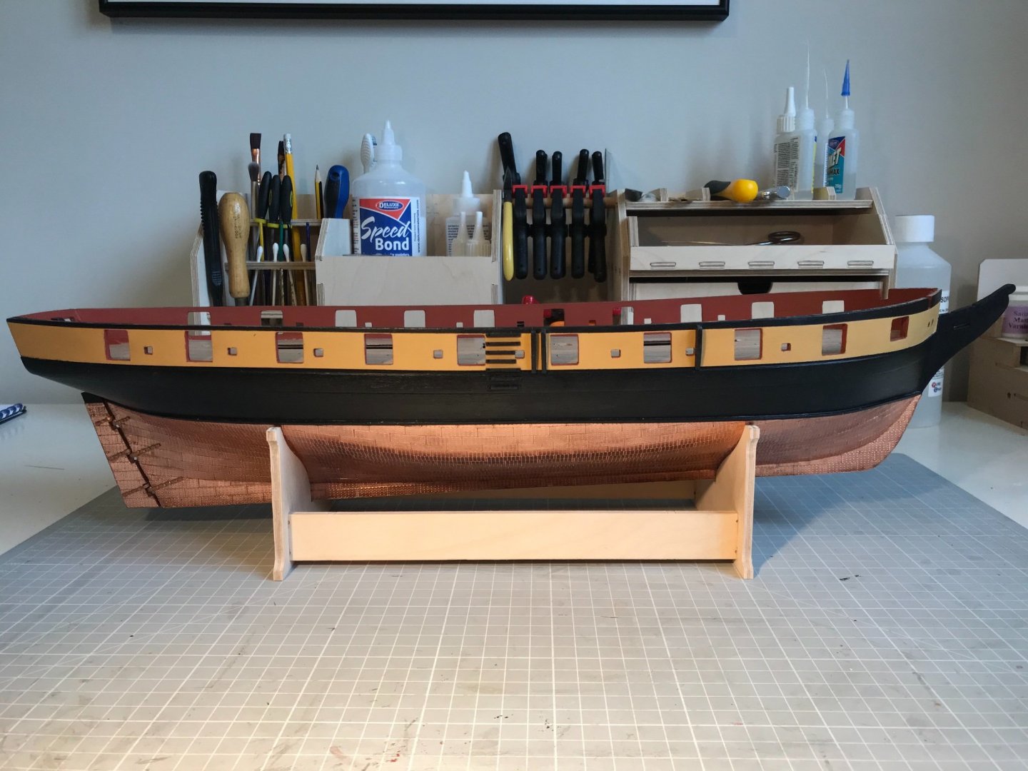
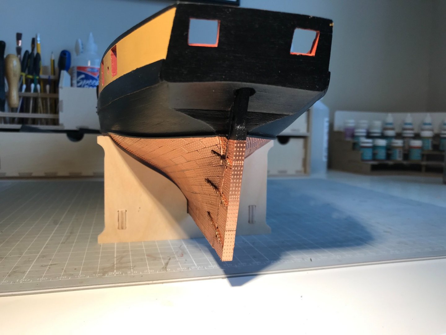
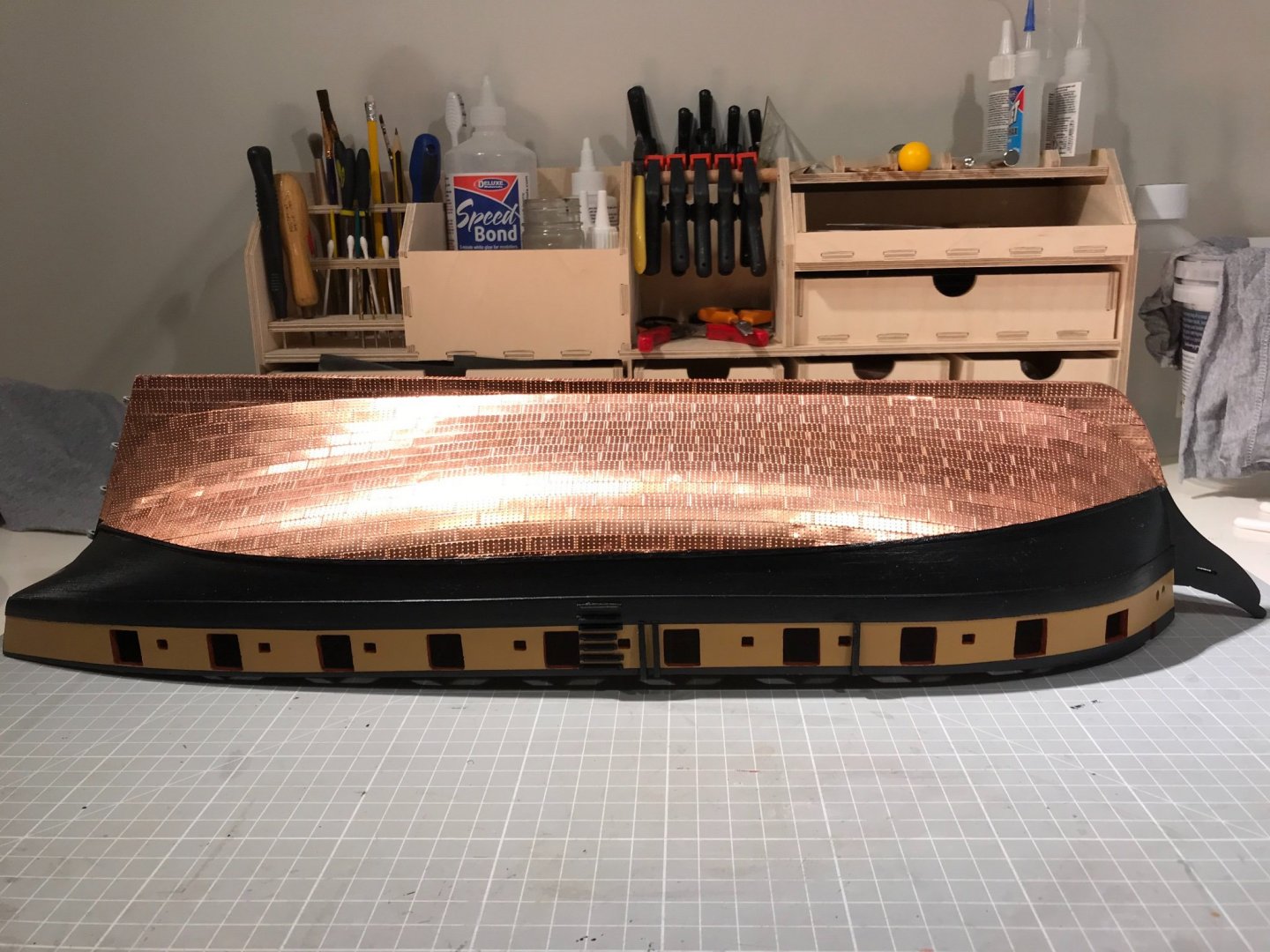
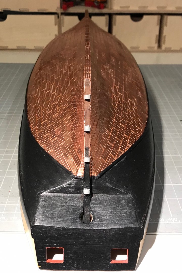
Copper is done! Just need to paint the sternpost, the leading edge of the rudder and the straps, and then attach the straps to the gudgeons and pintles. The learning: 2 drops of thick CA per tile hold a tile in place with a finger and a the tips of a pair of tweezers (I reserve a pair for working with CA since then end up with a coating), remove finger, remove tweezers, in that order, or you risk the tiles coming off stuck to your finger A little bit of glue seepage occurs - but don't worry (see cleaning!) cut with a pair of scissors. each tile takes about a minute to lay, unless it needs trimming, then it's about 10 minutes the waterline batten makes the final edge pretty easy and hides the inevitable imperfections getting a perfectly aligned edge on the sternpost is hard, but I left an overhang and then filed with as small metal file. Worked very well there, and on the rudder. The file tends to wrap the edge of the tile around the edge which is useful... the keel, rudder and sternpost are all 5 mm wide, a tile is 0.2 mm thick, so the covered thickness is 5.4 mm, but a tile is 5.6 mm wide, giving a 0.2 mm overhang (more if you have been a bit zealous with the sanding). I tried trimming the tiles but couldn't get the width accurate or indeed the cut edge straight. But really, who cares about 0.2 mm overhang? I would have left it but it was very obvious in the few places where I had sanded too much. I tried filing and it worked a treat, eventually wrapping the tile around those butting up to it be sparing and reuse your trimmings, there are very few spare tiles. In the picture below the pot on the left is unused trimmings, and on the right is the remaining tiles (26 of them), and there are about 800 on the ship So cleaning: Whatever patina you want on your copper I think you need to get the glue off, and probably the finger grease so I soaked a scrap of rag with CA glue remover and gave the copper a good rub down. It took about 5 minutes but i could see the large marks softening and coming off. I then soaked another rag in iso-propyl alcohol (propan-2-ol to the chemists - see more in minute) and wiped over again. It came up clean but the tarnish was obvious from some angles and quite blotchy. Patina: You can find many an article on this forum, but most usually conclude that it's a matter of taste. Well my taste owes quite a bit to Patrick O'Brian who refers periodically to a glimpse of salmon-coloured copper appearing as Surprise heels in the wind. I was reluctant to use an abrasive polish as they almost inevitably leave a powdery residue. And, full transparency, I'm a chemical engineer, so chemical cleaning seemed natural. You can find a discussion of "pickling" here where "Sparex" is used to clean brass. Sparex is an expensive form of sodium hydrogen sulphate (NaHSO4), which in turn is a partly neutralised form of sulphuric acid (and much safer in concentrated form). You can buy it very cheaply from pool-supply companies (described as sodium bi-sulphate) where it is sold for lowering the pH of things like hot tubs. make up a volume of acidic solution. I use a recycled 600 ml supermarket soup tub. Aim for about 50 ml of NaHSO4 in about 250 ml of hot water (add the powder to the water, not vice versa. This way the solution starts weak and gets more concentrated, where as the other way it starts very concentrated and then weakens. If anything goes wrong, you want the former, not the latter to spill on your workbench). You end up with a solution at roughly pH 1 which is not all that dangerous, but glasses and gloves are called for. I do this at my model building desk, but a a kitchen sink might make more sense. make up a volume of alkali solution. About 60 ml of sodium bicarbonate (baking soda) in about 250 ml of hot water - it won't all dissolve but that's ok. wearing gloves, dampen a cloth in the acid solution and wipe the copper all over. Don't go crazy and soak the whole ship. I wiped one half of the hull for about 2 minutes, then dunked the cloth again and wiped that half for another 2. then take another cloth, and dampen it in the alkali solution and wipe over the acid-treated copper. You will hear a bit of fizzing, nothing worse. You now have copper tiles covered in a dilute sodium sulfate (Na2SO4) solution, which when dry would leave a dusting of white crystals. take another cloth soaked in clean water and wipe off the Na2SO4 solution. Dry with a cloth and repeat. now do the other half of the hull. To dispose of the solutions it seems best to neutralise one with the other. In a sink very gently pour a little of the acid into the alkali container - it will foam like mad, so start very slowly, eventually it will calm down and once you have mixed them all it should be a pretty neutral solution of Na2SO4 that can go down the drain. Rinse out your cloths - I give the acid cloth a slow dunk in the alkali first This gave a very shiny uniformly coloured copper finish. Which is what I want. To keep that finish I then applied two coats of acrylic satin varnish. Here are the results:


- 109 replies
-
- 8
-
-
- snake
- caldercraft
- (and 1 more)
-
Well, what a beauty. And absolutely worth the wait for the update. I was telling myself that I would wait for the model after Sphinx (since Snake has some time to go). But now I'm not so sure, she is so damned beautiful. I think we should all recognise that detail and quality of the kind you are offering won't be cheap, but I certainly hope there is high demand and decent margins for you, meaning that making this your full-time job becomes realistic. Just imagine what choice we would have then!
-
Thanks Jason. I’ve carried on following the natural line. It looks fine where it meets the waterline. It had occurred to me that I could stick a horizontal band on top, but doubt I’ll be tempted.
-
What a beauty. And how you find the time while working, I cannot imagine. BW Mike
-
Hoorah! I’m sure you are steaming along, so we’ll just have to wait until bandwidth arrives.
-
Thanks James - of course I’ve also got used to building boats at super-human speed.
-
Hi Chris. Hope things are going OK with you, the business and Sphinx. I had got used the breakneck progress you were making, and miss the frequent updates. I'll try to be patient (and concentrate on the build in hand). Mike
-
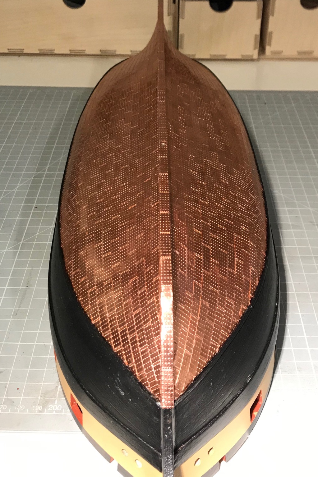
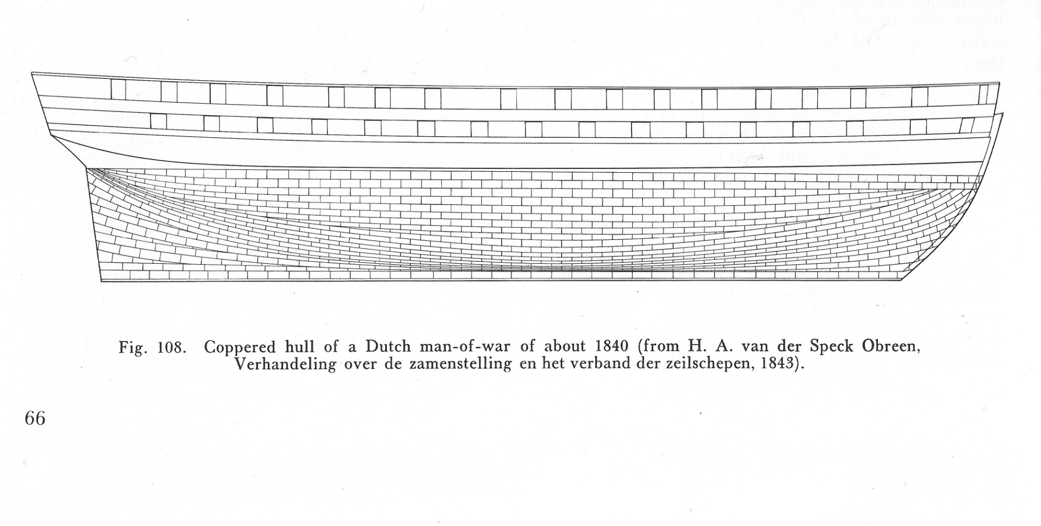
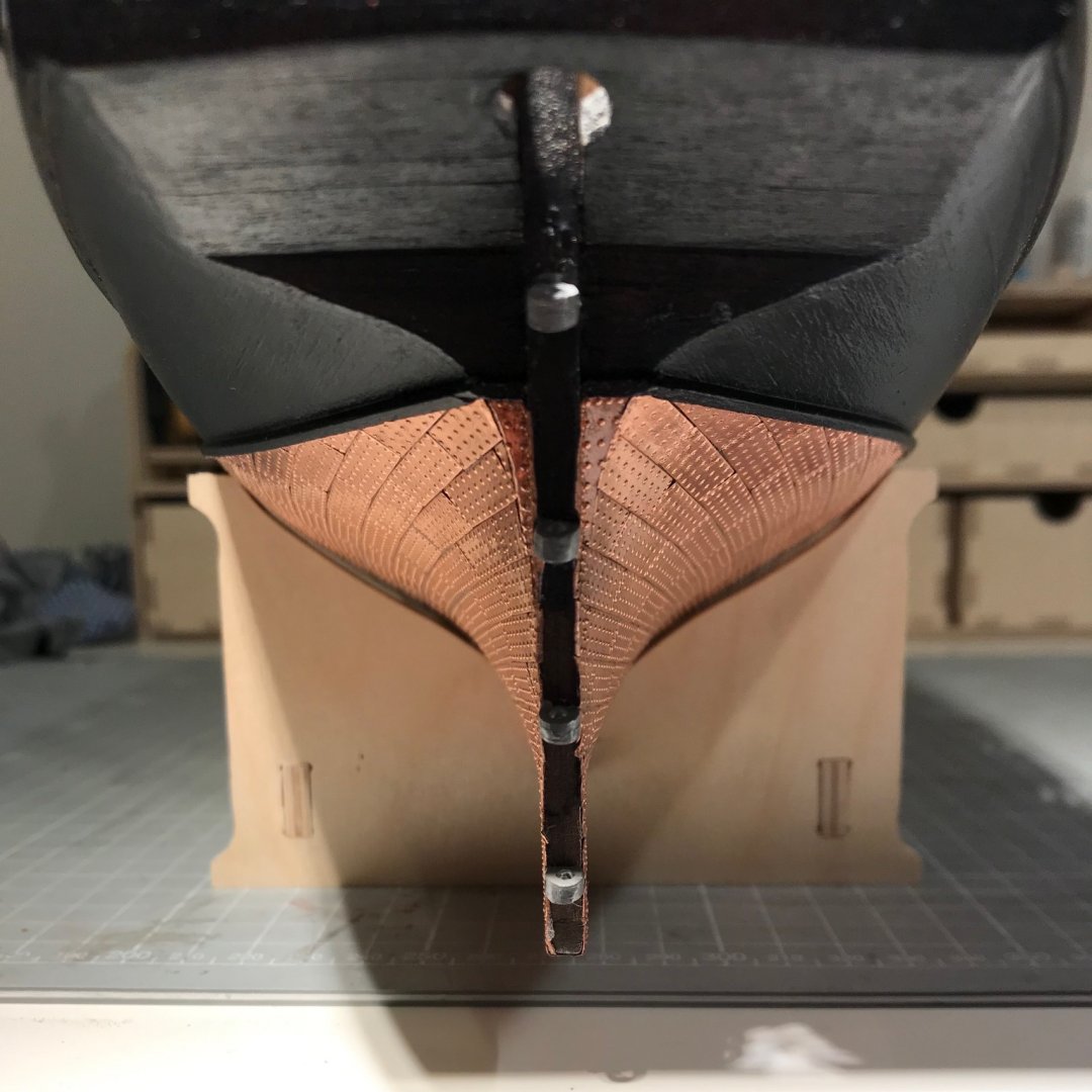
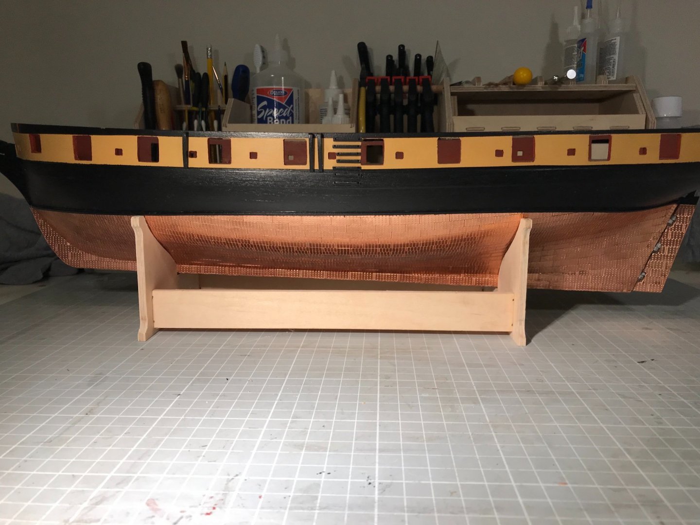
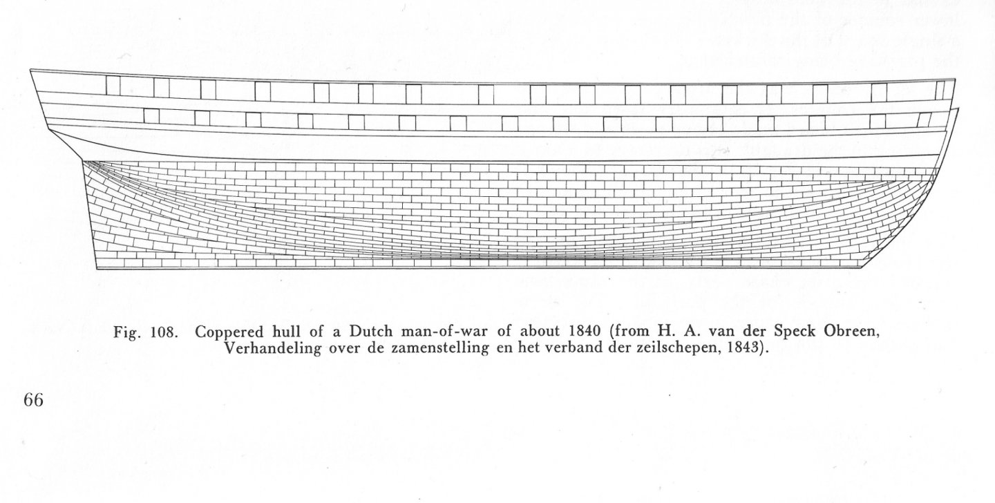
Well Joe, here's the thing. The two decker (image) has copper 30 mm in depth and 230 in length - a ratio of 1 : 7.67. My Snake (model) has copper 60 mm in depth (amidships) and 460 mm in length (exactly twice of the 2- decker image) so also a ratio of 1 : 7.67! It could be that the relatively speaking they differ in their beam - and certainly the Cruizers don't have the most elegant of lines, but then nor did two deckers. I've given your coppering quite a lot of attention - mainly on the subject of patina and natural (or should I say nature-enhanced) ageing. Yours seems to run quite happily in horizontal rows, where as mine was very keen to wrap around the hull vertically - perhaps because I kept quite an abrupt transition from planking to keel. Anyway I took the day off work while but Admiral and Rear Admiral were head-down WFH (the Vice Admiral is hundreds of miles away very close to Snakes birthplace) . Gave me ample opportunity to push on with copper, and I'm quite pleased with how it looks (that's acquired British understatement, I'm thrilled). Onwards!
-
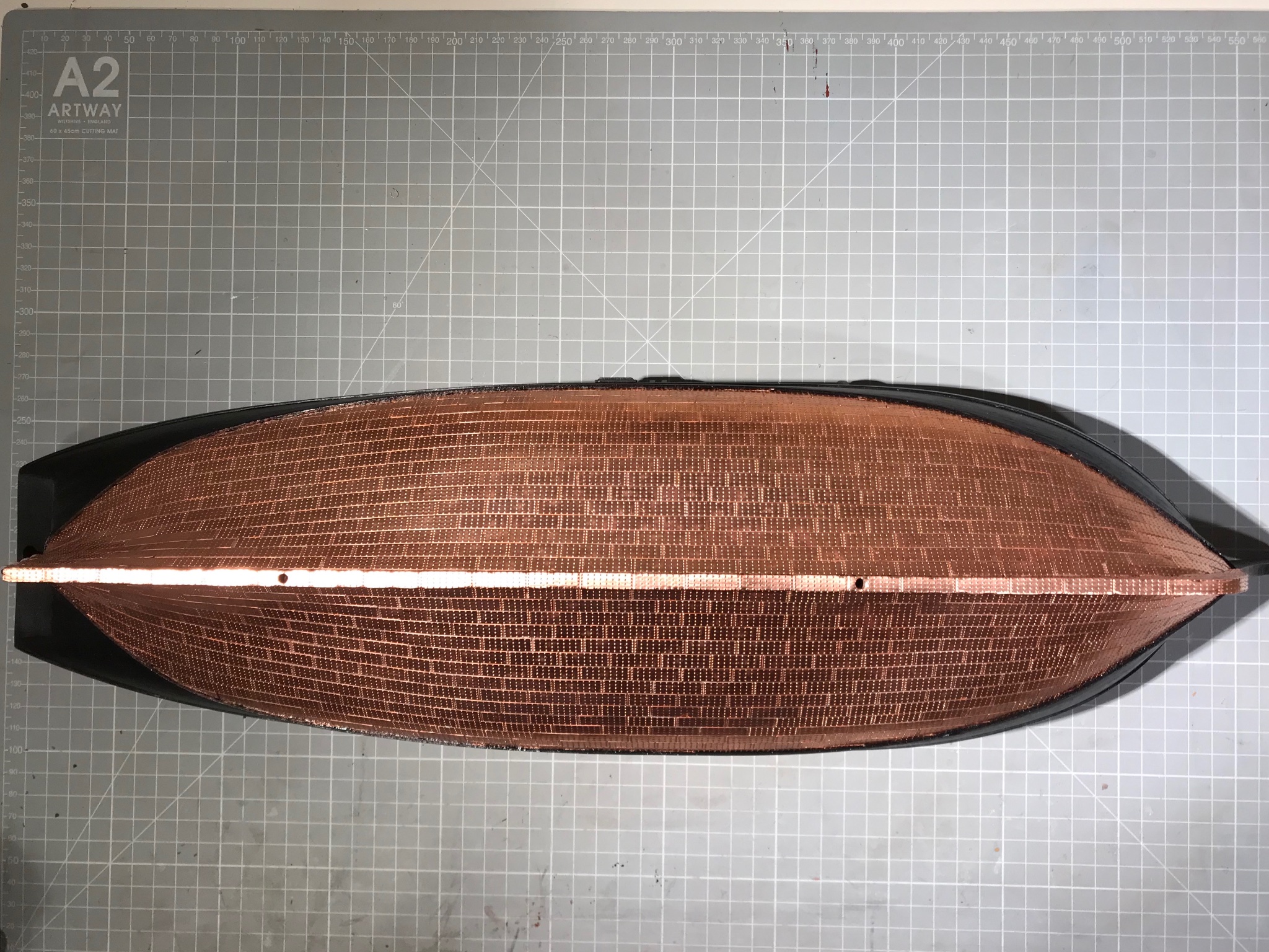
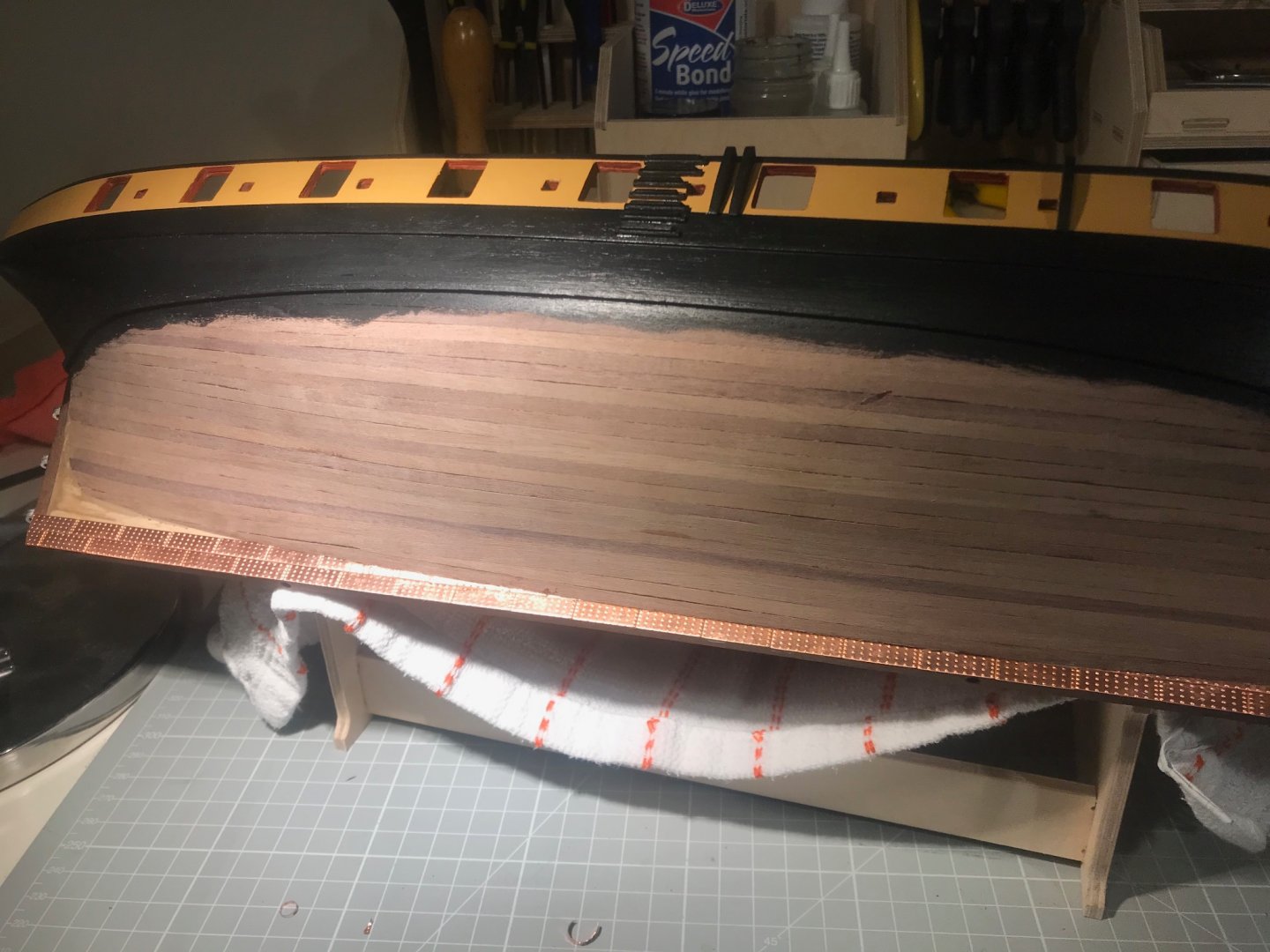
And so copper... In short, it's a joy. Slow and steady and according to a plan - pretty much the heart-beat of model ship building. I find the copper tiles really quite forgiving: nicely annealed so they bend very easily, cut with a small pair of scissors, the rolled edges are very helpful with slight gaps, since the reflections at the joins make it very hard to detect glimpses of walnut with two dots of medium-gel CA they "float" about on the hull surface waiting to be aligned And the plan? Broadly inspired by the Petrejus' drawing in his incomparable Modelling the Irene (as an aside, if, like me, you are new to modelling, this book has such a wealth of beautiful line drawings, that it doesn't matter what you are trying to build, from wherry, to four-decker, there is so much to be learnt). Anyway, his plan... From the keel up he shows the copper sheets laid following the natural run of the hull until about the belly-line of the hold (that's my plan), a set of stealers fore and aft before another band eventually meeting a band of two laid horizontally at the water-line. Because the Snake's keel is not parallel to the water-line, I'm not convinced that a horizontal band is sensible, or indeed that steelers for the converging lines are needed. This is where I am up to. And I think I have decided to carry-on just following the natural line of the hull, meaning that the line of tiles will "droop" below the water-line batten. But I might go and have a look at others' work.

- 109 replies
-
- 4
-
-
- snake
- caldercraft
- (and 1 more)
-
Yes, the invitation is quite a distinction, as is the display of your paintings. Sorry you can’t go, though.
-
Hi Jim, I just stumbled on these, and will concur with everyone else - you have an exceptional talent. The thing that most impresses me is the way you catch perspective and line, on objects that have such subtle, graceful shapes ie ships, waves and clouds. And then skimming through again, your use of a splash of colour. Your paintings of the Arctic convoys bring back memories of my youth - not in the 40s, but the 70s - where they were frequently referenced, and featured in an Alistair MacLean novel (HMS Ulysses, I think). But for all that water-colour and your talent lend themselves to grey ships, grey sea and white wave tops, it is your paintings of sailing ships moored, or near the coast, that have brought me most joy. So let me give you every encouragement. We know of the great ships of the 18th and 19th centuries as being the largest and most complex machines of their time, but that might lead us to think that they were manufactured in the very methodical ways in which - post Henry Ford - we manufacture most things today. Early in the your posts here, you showed a small painting of a ship under construction at Bucklers Hard, which correctly shows that ship-building was often closer to cottage industry than industrial production. I recently read Peter Moore's Endeavour, whose descriptions of 18th century Whitby (then Britains most productive ship yard), describes ships on props stuck up creeks, rather than the crisp dockyards of Portsmouth. As it happens I'm drawn to both Whitby and Bucklers Hard - I live in Yorkshire, but have family near Bucklers Hard, and am currently building a model of HMS Snake which (I'm tempted to say who!) was built there. So if either of those locations attracts you, please feel encouraged. Best wishes, and, well, thanks for sharing Mike
-
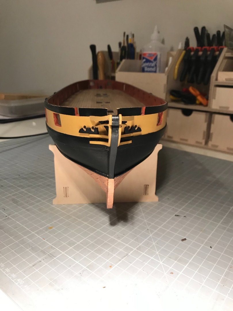
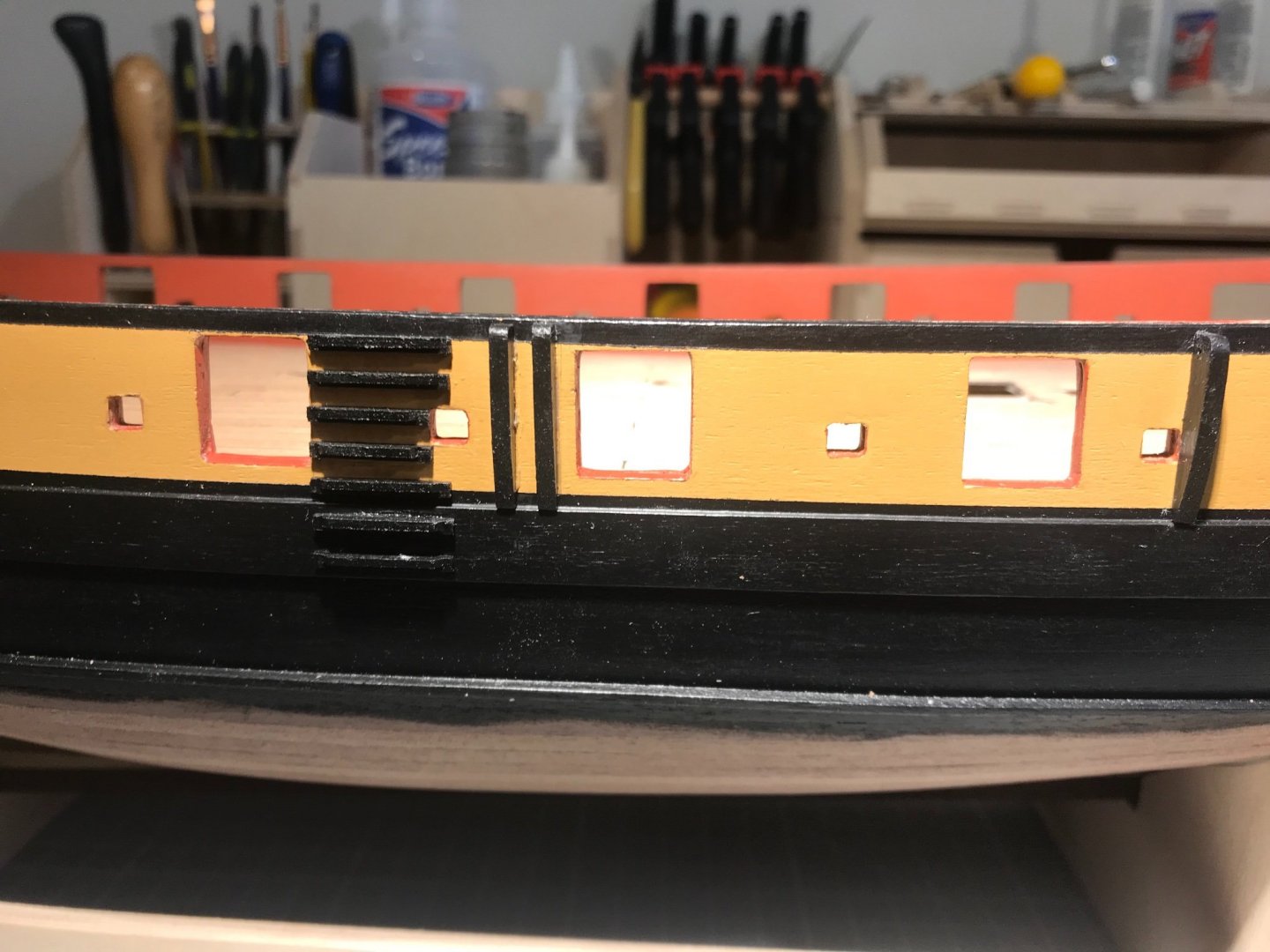
A little light relief: Stern Facia Knees. Quite the easiest installation to date. Angles easy to sand, dab or two of CA, and it's done. Side Steps and Fenders. Keeping the steps aligned was a challenge, but not really a great one. The Fenders I made entirely from 4x2 walnut strip, rejecting the pair (not six?!) provided in 2 mm ply. Took the radical decision that in my work-a-day ship the 1st Lieutenant would not be paying for yellow ochre paint on parts to be rubbed against quays, boats and other surfaces, or stamped upon by tarry feet. So all are work-a-day black. I'm pleased to have them visible. Fitted the rudder. A modest challenge since the white-metal castings varied from fair to poor, but most importantly varied. The length of the pins on the pintles needed to be trimmed, the spikes on the gudgeons were elliptical, and the holes in the gudgeons needed drilling out. Squared-up the cutouts on the ruder first, and then glued the pintles in, snug in the top corners of the cutouts. Clamped the rudder in place and then marked a level on the sternpost giving the bottom of each pintle, so the top of each gudgeon. Fixed the top gudgeon: drilled for the locating pin 1.5 mm lower than the marked level. Glued the gudgeon. Checked for alignment. All good, repeated for 2nd, 3rd and 4th. Naturally everything was fine until the last one - as I hurried to get done by lunch. Hole too hight, cutut too short, locating pin snapped. Had some lunch, then carefully remedied. But now onto some serious stuff. Here's a glint of copper:

- 109 replies
-
- 5
-
-
- snake
- caldercraft
- (and 1 more)
-
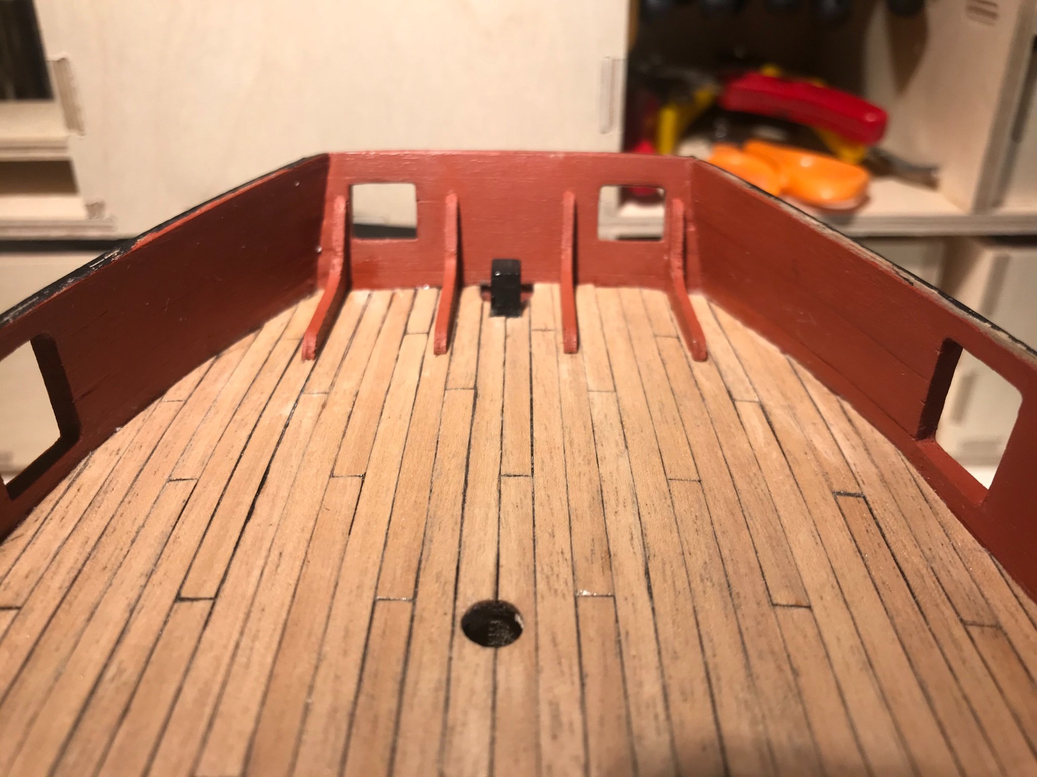
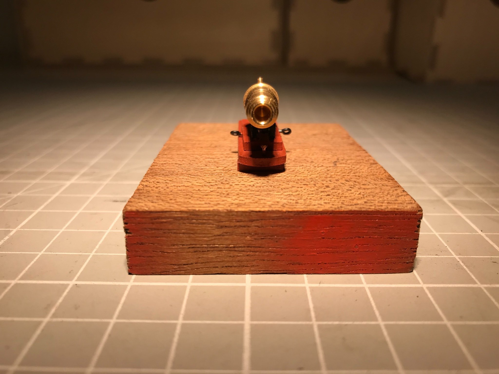
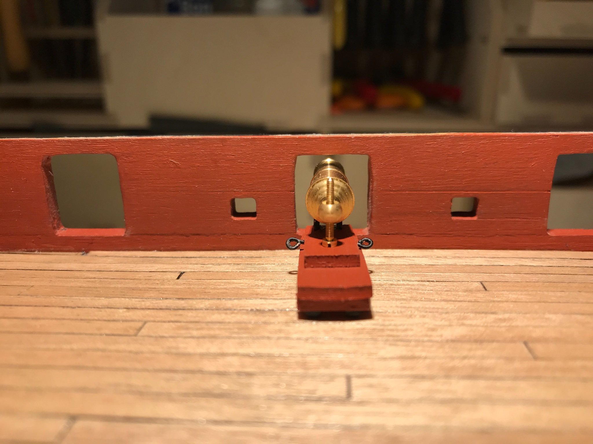
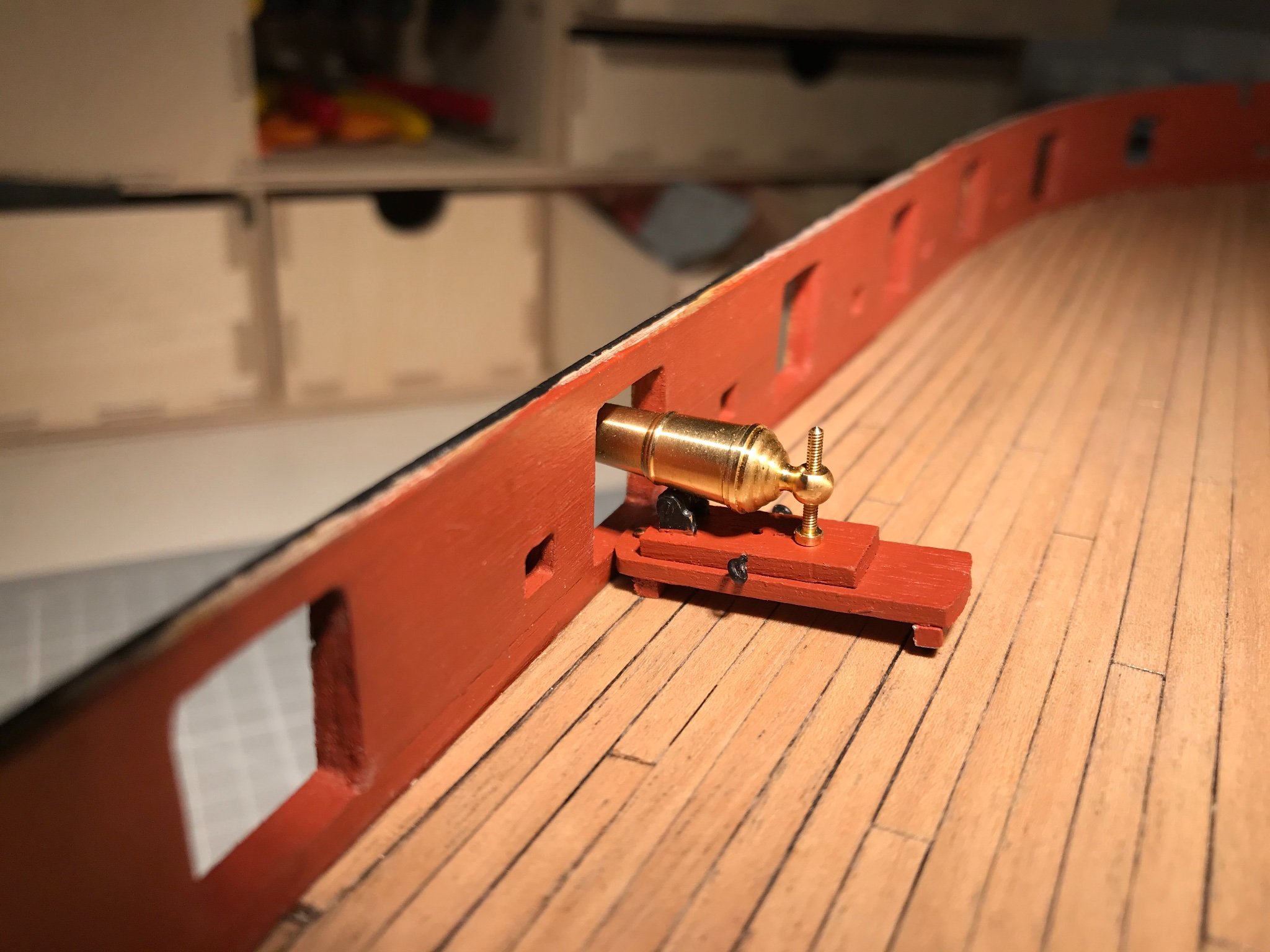
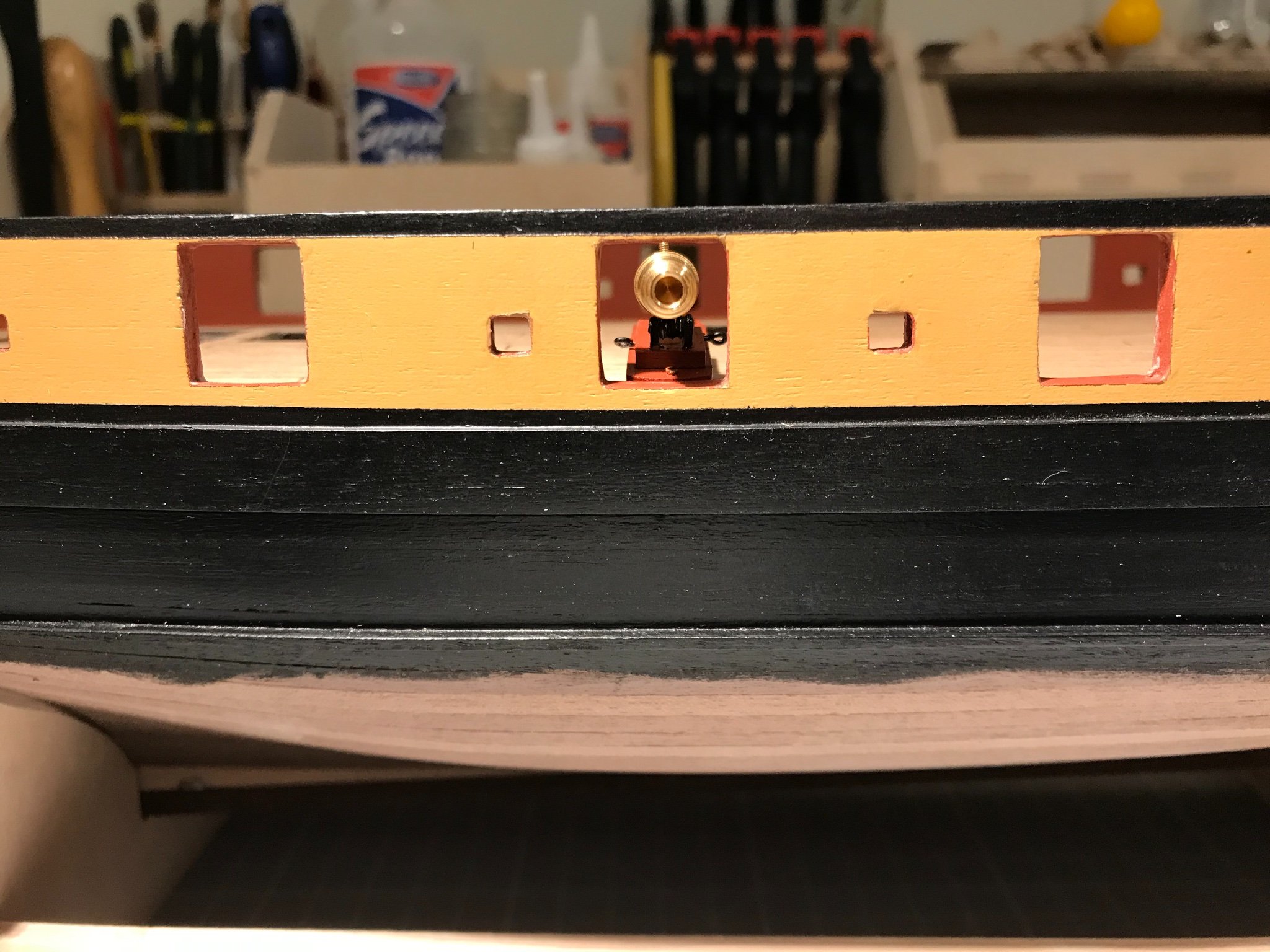
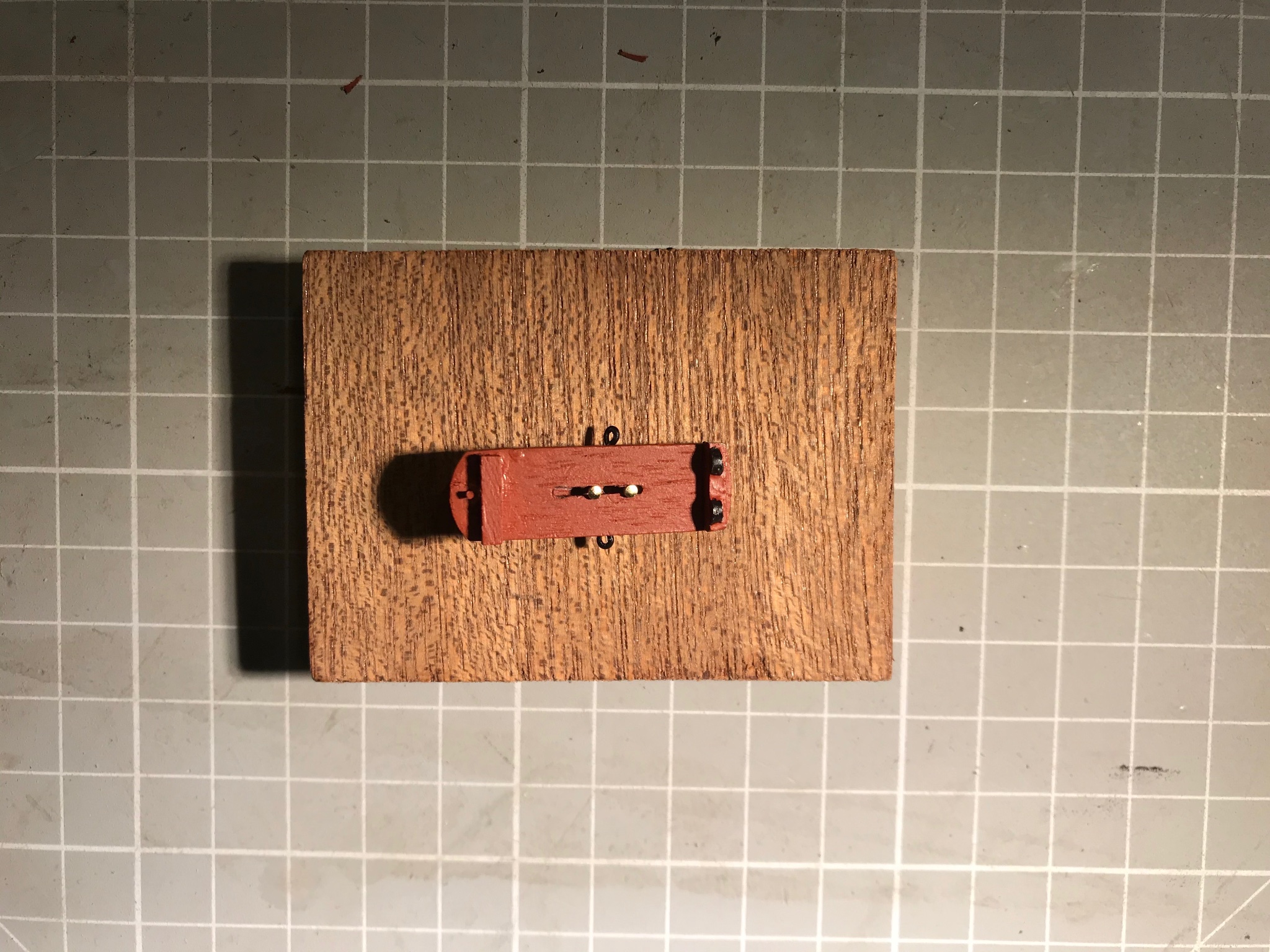
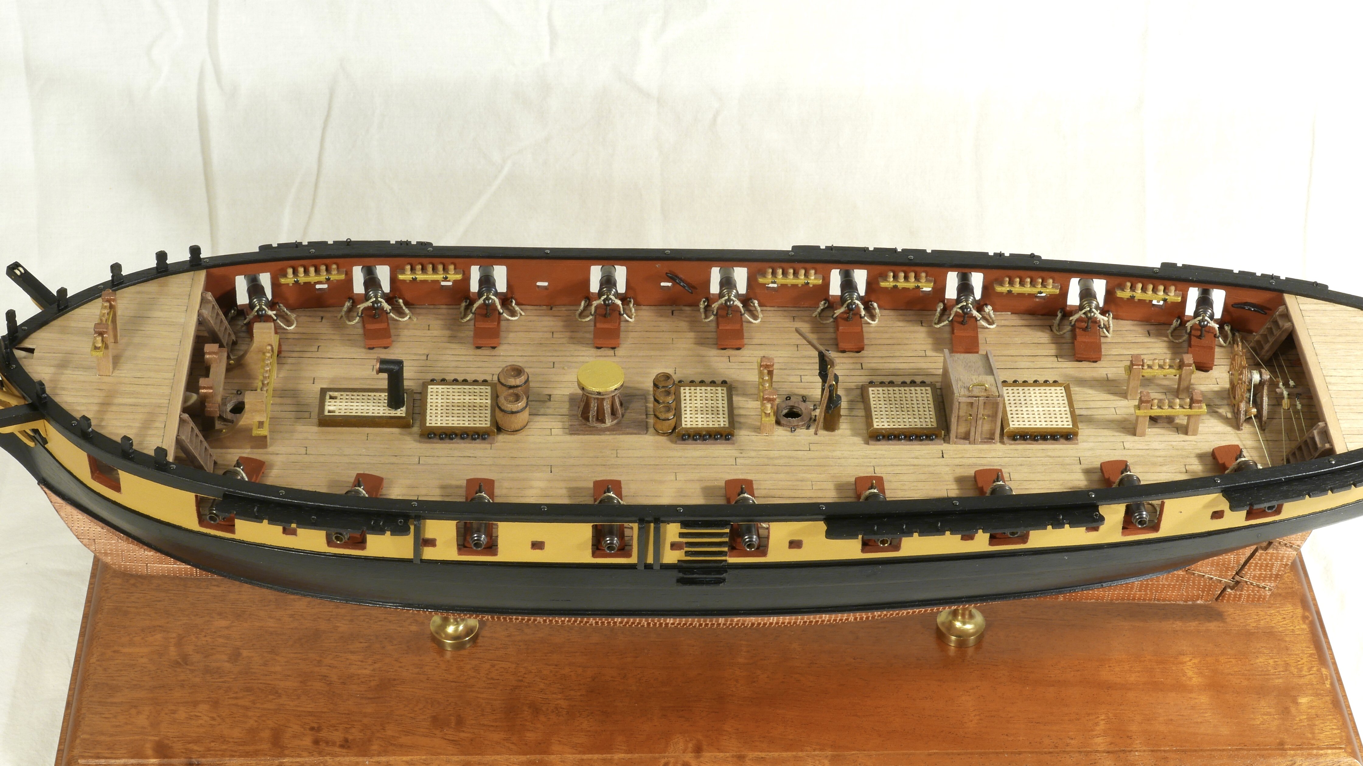
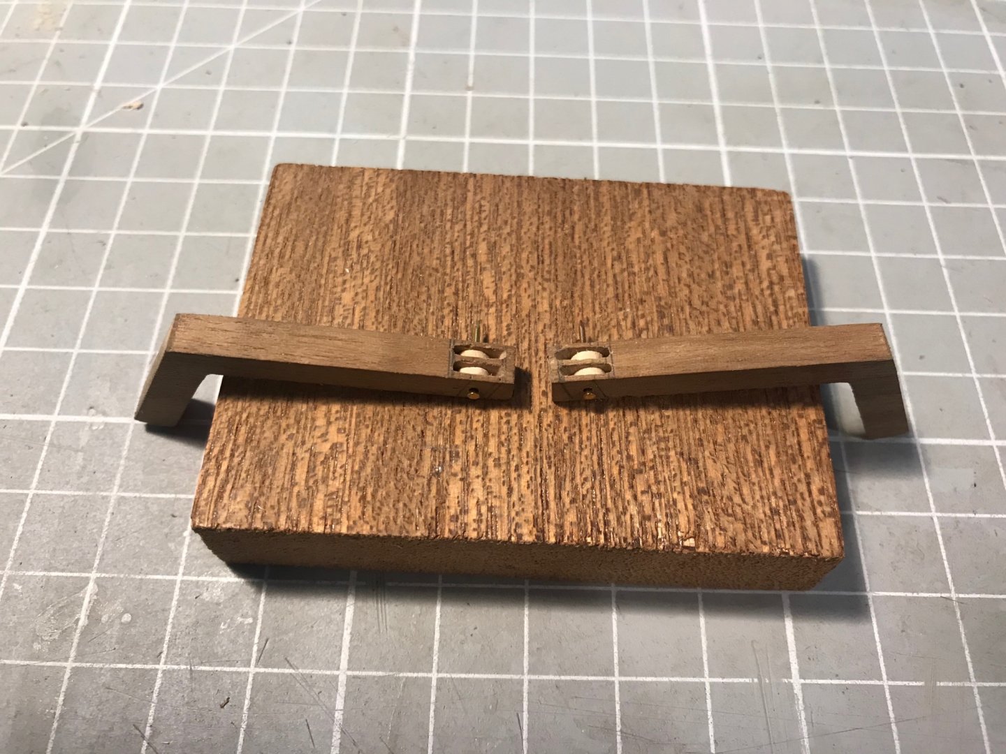
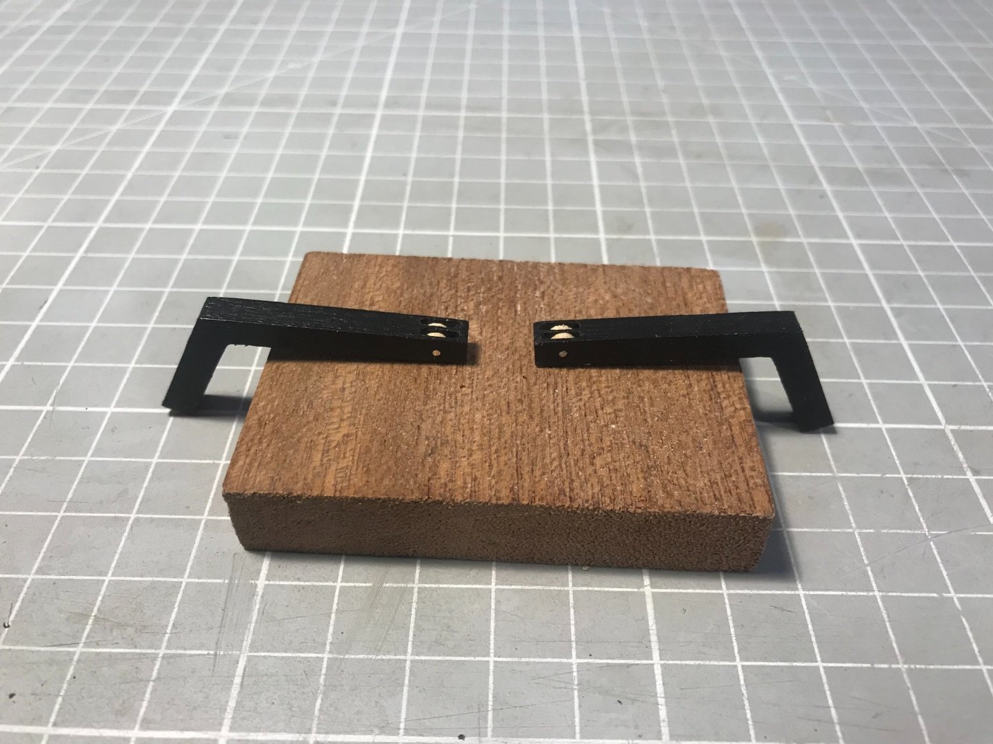
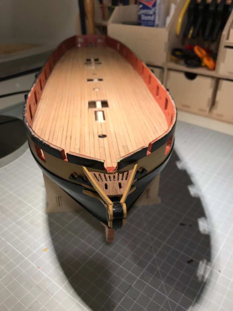
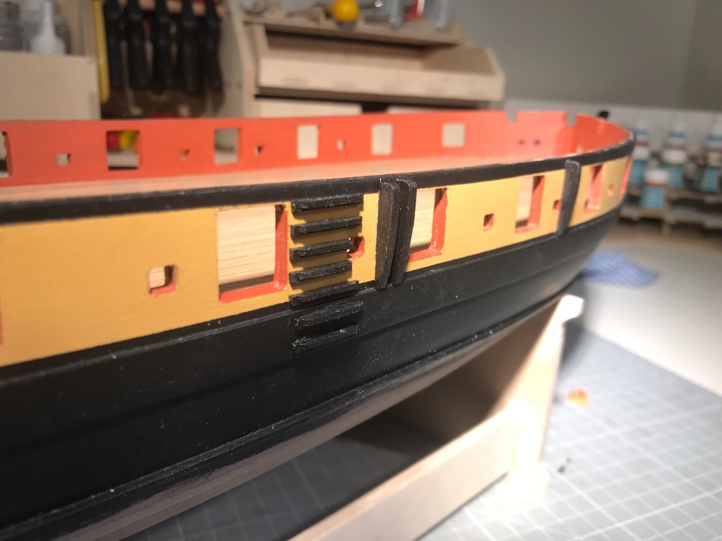
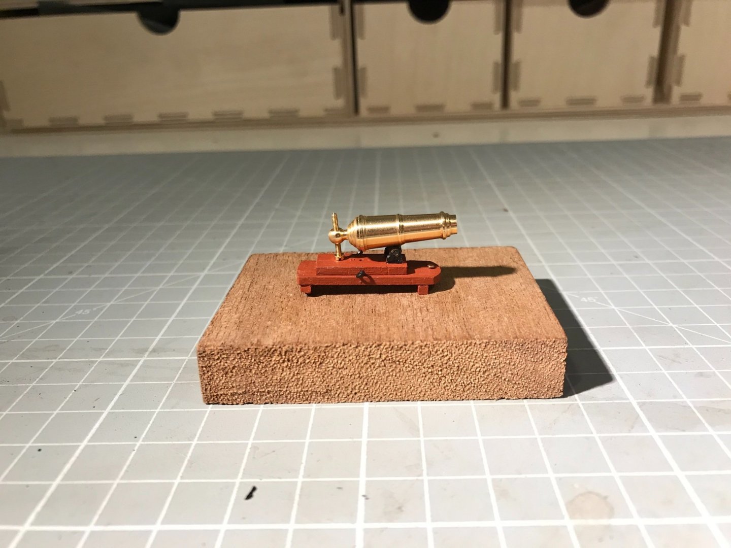
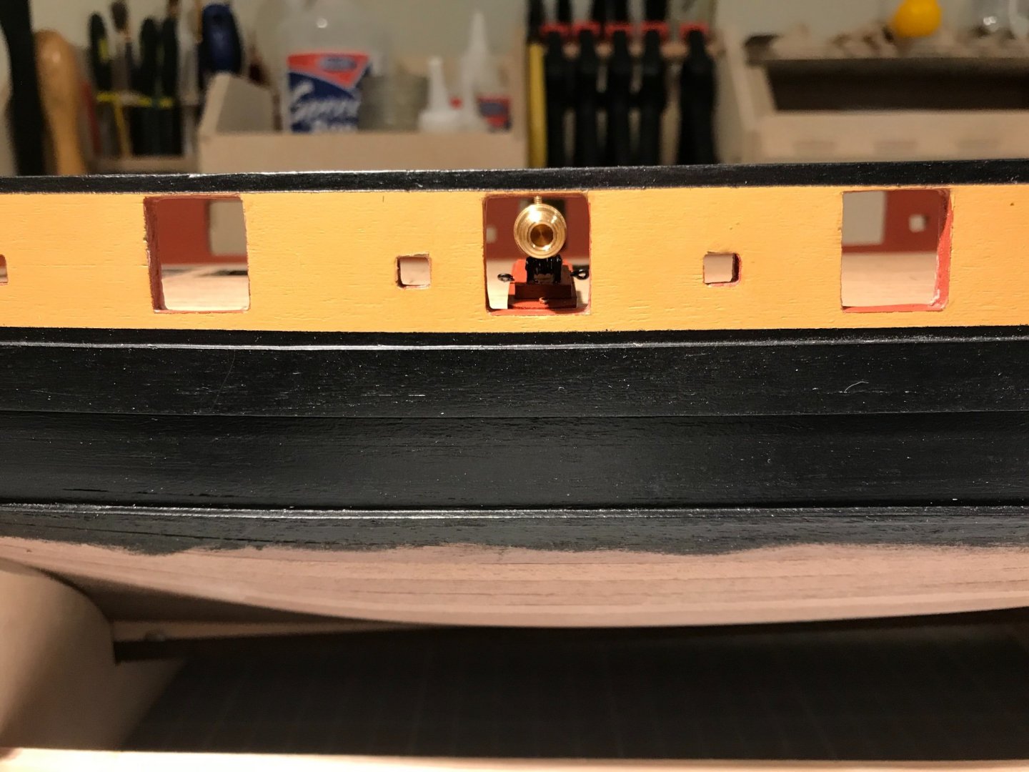
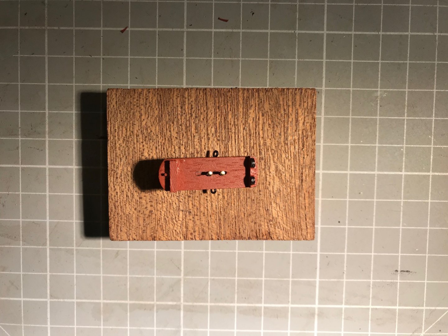
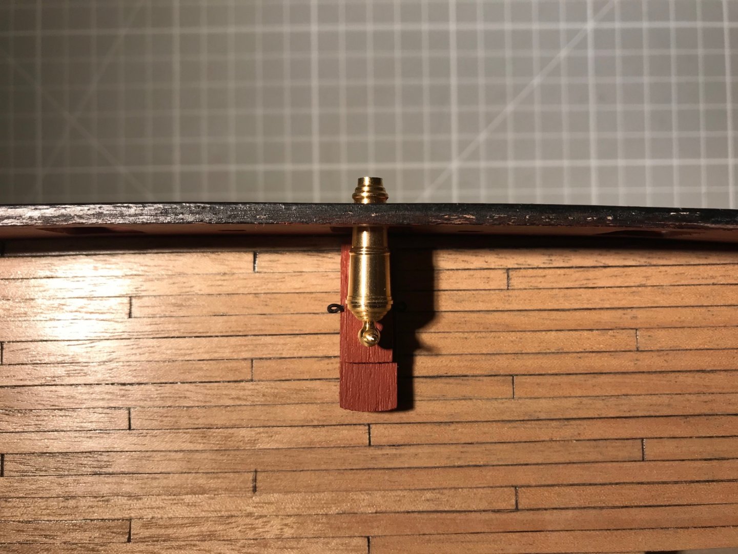
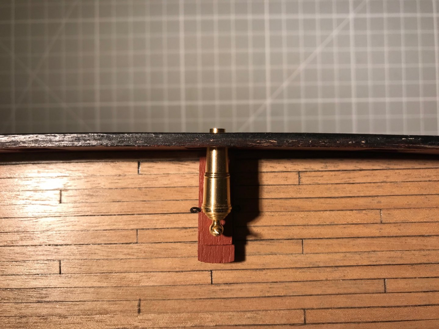
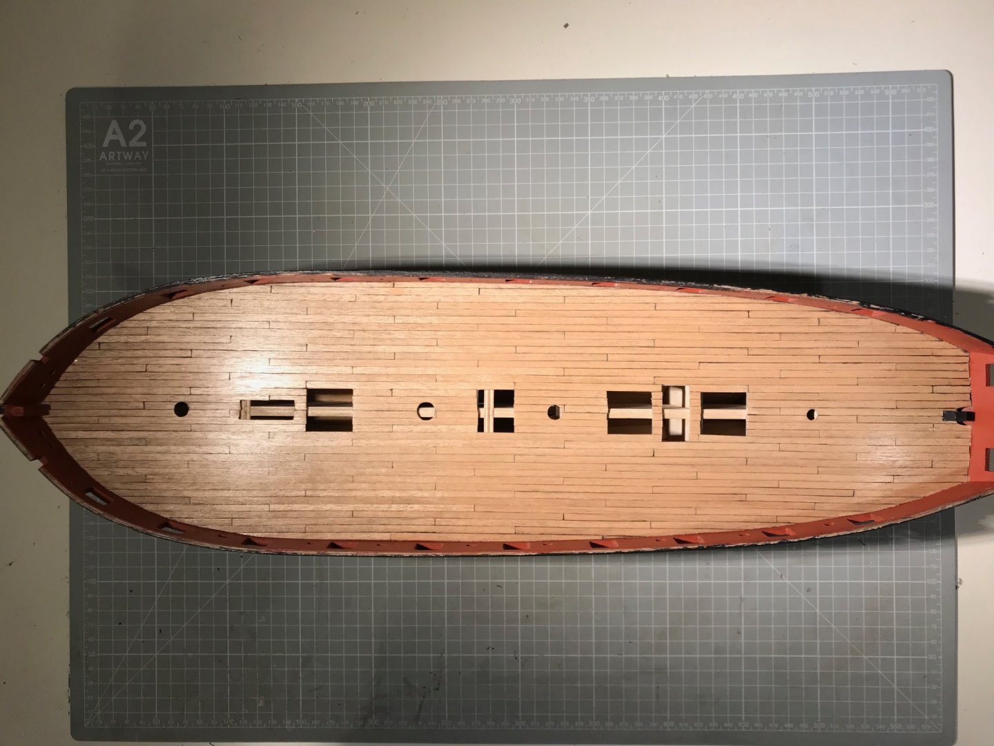
So, to assemble a carronade and offer it up to a gun port. All reasonably straightforward, apart from trimming the photo-etched (PE) parts. I painted all of those black (I might chemically blacken them in the "production" run - and I've not treated the barrel at all - it will be blackened, assuming I can follow the instruction on this Forum)., and while I was careful to pass a 1 mm drill bit through the components designed to act as the pivot - and so sit on a 1mm axle - I also needed to counter-sink them slightly to slide them on. Assembled it and offered it up to the port. As every single perspn who has ever built this model discovers the carronade sits much too high. Now, there is historical precedent for this set of circumstances: It seems that Scorpion had her carronades set too high - the bed on Scorpion sits above the port sill, and below on Cruizer. You can see, also, that in this case both ships carry their carronades inboard, with a pivot set in the deck. And so, like everyone else I set my carronade on a block, though I did add a pin for verisimilitude. I also, for experimental reasons attached the slide with a pair of pins allowing it to slide. You can see the underside in the first photograph below, and then in the two overhead shots see the result with the gun run out and run in. The pins have to be separated to make the slide move parallel in the bed, which means the range of movement is not great. I expect when I come to install the guns I will pin them - with one pin visible as a pivot and the other attaching slide to the bed, and then passing into the deck. On a final point, the deck planking looks fin in these overhead shorts. Don't think I will do the port sills - the Cruiser model from the NMM does not show them. Not sure what I will do next - certainly not the fore and aft platforms, or the bulwark capping rail as suggested in the book of words. So I'll check to see what others have done. Hope it's not the copper, as I'd like a week or two of variety after the deck planking.
.jpg.89a759aed8ea2643a228c7d5ec40742a.jpg)


- 109 replies
-
- 4
-
-
- snake
- caldercraft
- (and 1 more)
-
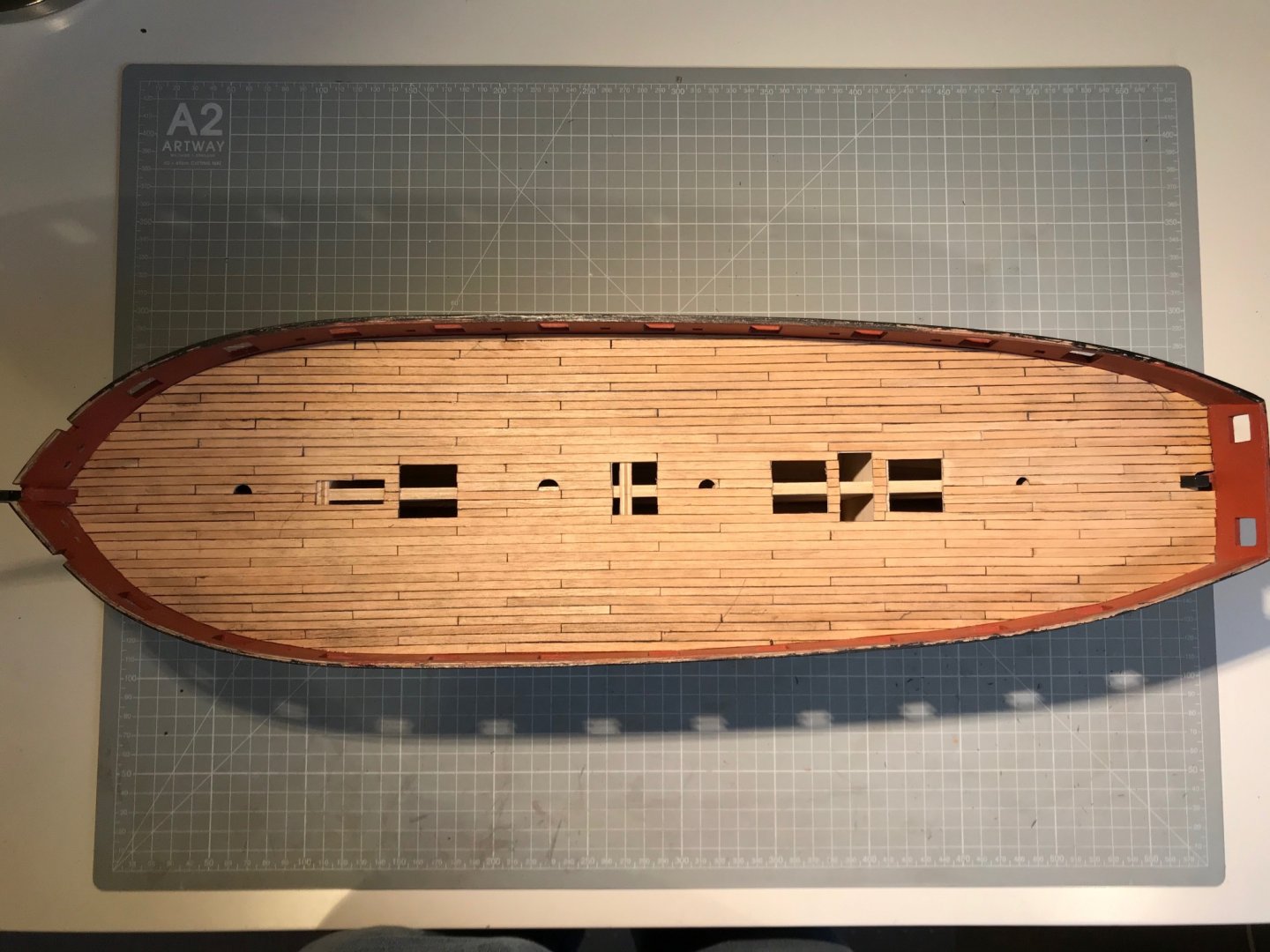
Deck is fully planked. Have you noticed that the go-to explanation for difficulties in model-ship building is quality of strip wood? Well, let me tell you about the Tanganyika supplied with the kit. The good points are that I like the colour and the grain very much. That's it! It's a bit shaggy, but a little sanding fixes that. The real issue is that quite a lot of it is seriously warped (in the plane of the deck), but worst of all it is different widths, and I think I had one strip that turned out to be a different thickness. Keen readers might remember that I marked-out the deck beams following the NMM plans and aligning plausibly with the hatches, masts etc. That gave me planks of roughly 12 cm in length that all needed to be laid parallel and snug against each other. Doing that with warped strips of random width was not a lot of fun. There is also scarcely enough timber supplied so there was no choice but to mix and match different strips. The result, before sanding is this: At this point I half-imagined I would either rip it up, or plank over it. You can see seams (and gaps) or random thickness and a lot of smudged pencil. Let me explain: the approach I took was to bevel each strip so the top-side was slightly narrower than the deck-side, and then blacken the chamfered edges with a a very soft 6B pencil. I would then present the strip to the marked-up deck, and mark where to cut the strip. This I did in a miter-box with a razor saw. I then chamfered and blackened the ends of each plank. I used a thin line of thick CA glue (Deluxe Materials Roket Max), which gave about 5s for fiddling. Problems: I bevelled with a sanding block while holding the strips in a pair of smooth pliers, but the strips are very floppy so getting a constant angle doesn't seem to have happened (but Tanganyika is not suitable for planing), the graphite from the pencil goes everywhere, but the really tough bit is getting the planks parallel and snug when they are warped and and of random thickness (I'm complaining too much now, but it was very frustrating). Anyway, I sanded and varnished. And while I'm not delighted, once the deck is fitted out, I'm guessing the caulking lines won't be so obviously varied in thickness, and I really do like the colour - nothing flashy on this very workaday ship. If I were doing this again (I wouldn't, I'd buy one of @chris watton's new creations with etched decks) I would pay much more attention to the width of the strips, and experiment in advance (and so have plenty of timber to start with). I still think bevelling and soft pencil should work, but I would use some kind of clamp to hold them while bevelling, and probably not cut individual planks, since it turns out that with a chisel-edge scalpel you can cut a little v to simulate a butt join. I also wouldn't cut our the hatches, or interrupt the run of the planks for them. Next up "the lower quadrant sills", though I had better check that the fancy turned-brass carronades mount properly (spoiler alert - they don't)
- 109 replies
-
- 2
-
-
- snake
- caldercraft
- (and 1 more)
-
Truly exceptional Jason. The quality of the final model, and your well-documented journey of learning and discovery, are inspirations to anyone, like me, following in your footsteps. And while I have already learnt a lot on technical matters, I think the biggest point is your patience, and obvious enjoyment of small, individual pieces of progress. I have no real expectation of replicating either the technical proficiency or the patience, but I know I'm already doing a better job for trying. A final point: this won't be a final point! I do hope you are still active on the forum so I can ask many questions in coming months and years. Perhaps you might like to fully rig your Jason - that will keep you active on the site. So, many congratulations - for finishing a project started in pre-history, and doing it in such style. Mike
- 800 replies
-
- 2
-
-
- snake
- caldercraft
- (and 1 more)
-
There are reasons for that - first the room is less than 9 m2 in area and second, my working from home desk is immeditely behind me when I’m working on the Snake. So any mess is visible to work mates. But thanks for noticing!
- 109 replies
-
- 1
-
-
- snake
- caldercraft
- (and 1 more)