
Mike_H
-
Posts
244 -
Joined
-
Last visited
Content Type
Profiles
Forums
Gallery
Events
Everything posted by Mike_H
-
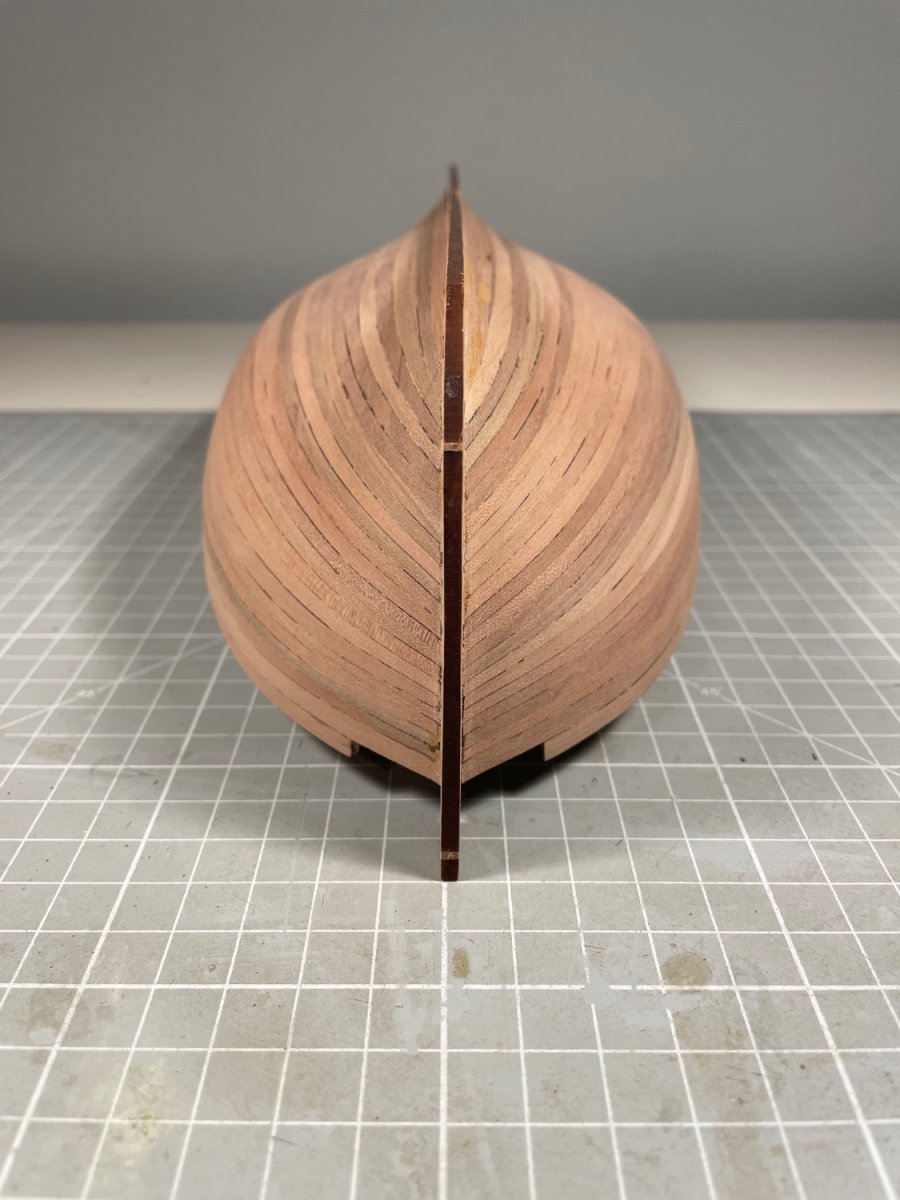
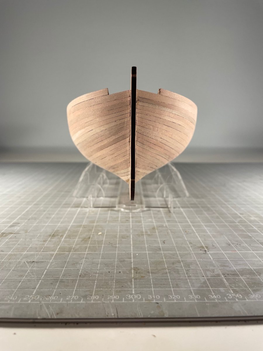
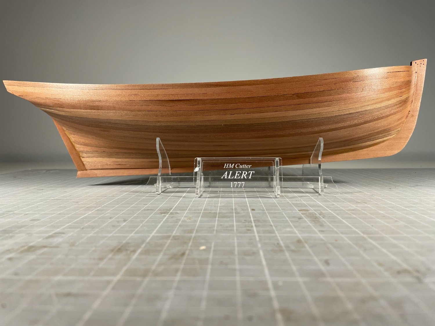
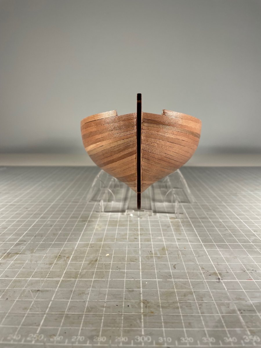
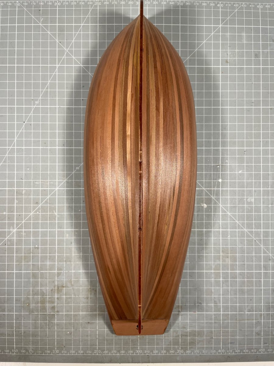
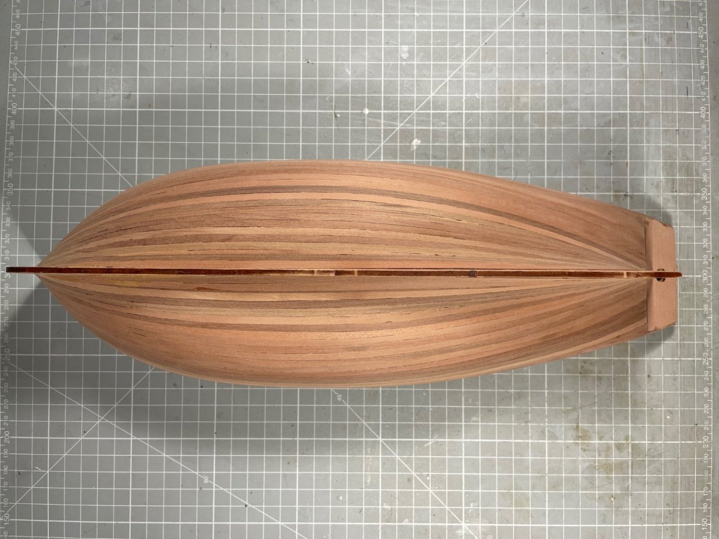
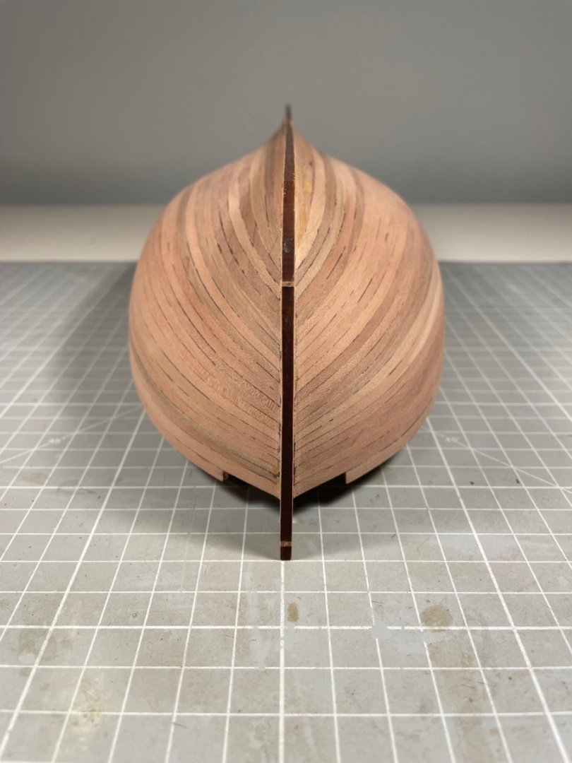
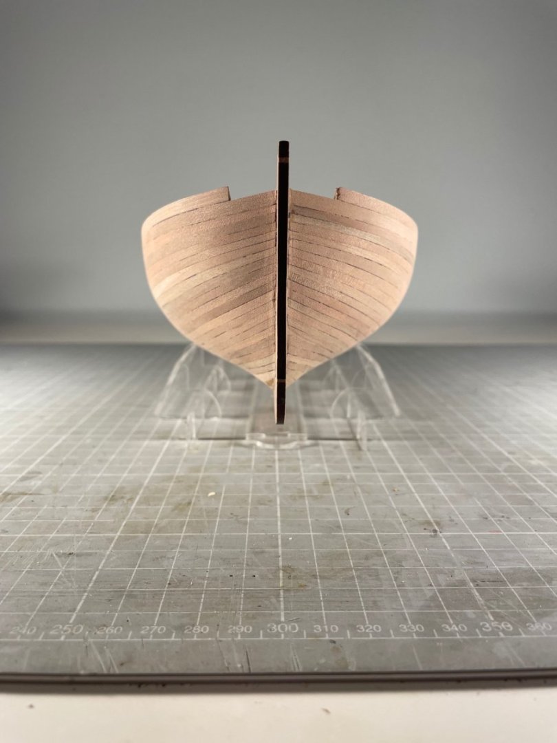
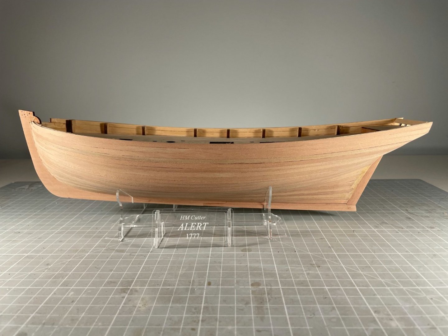
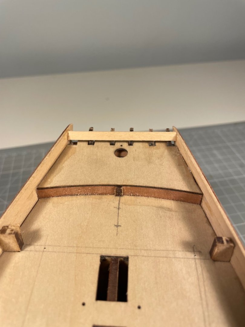
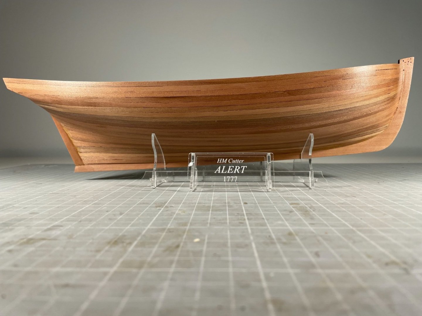
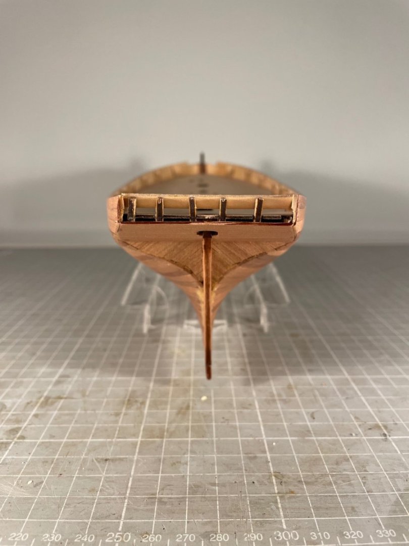
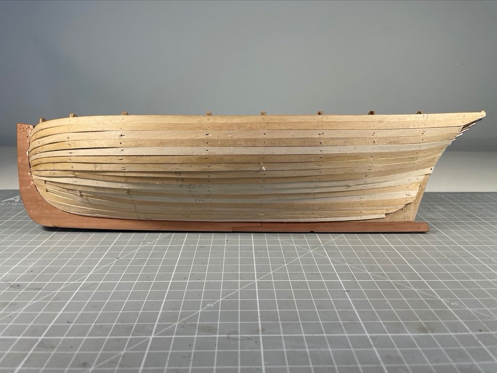
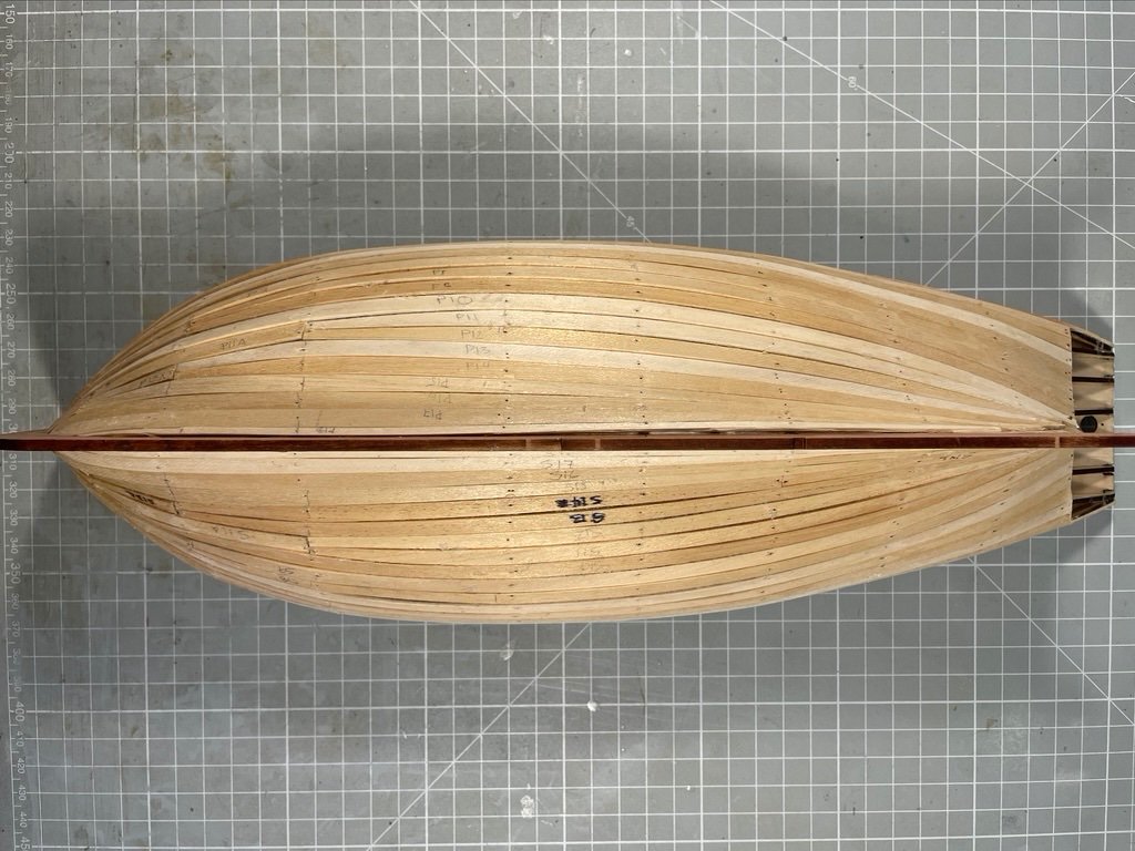
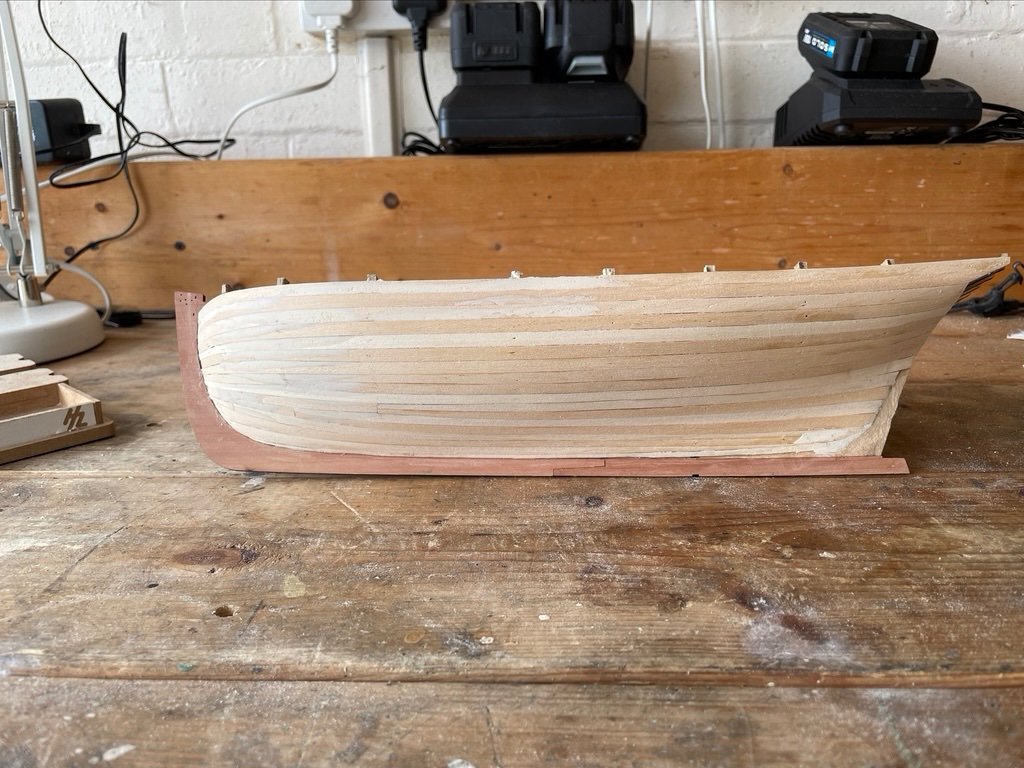
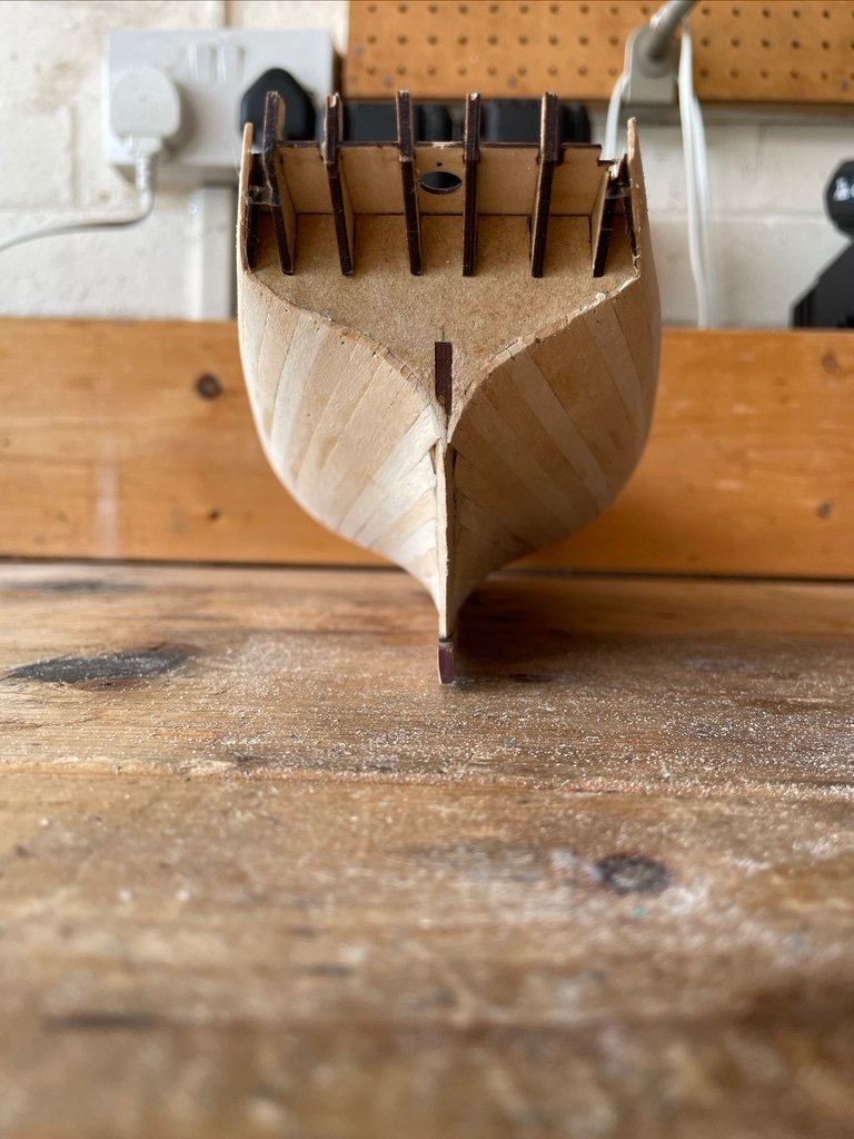
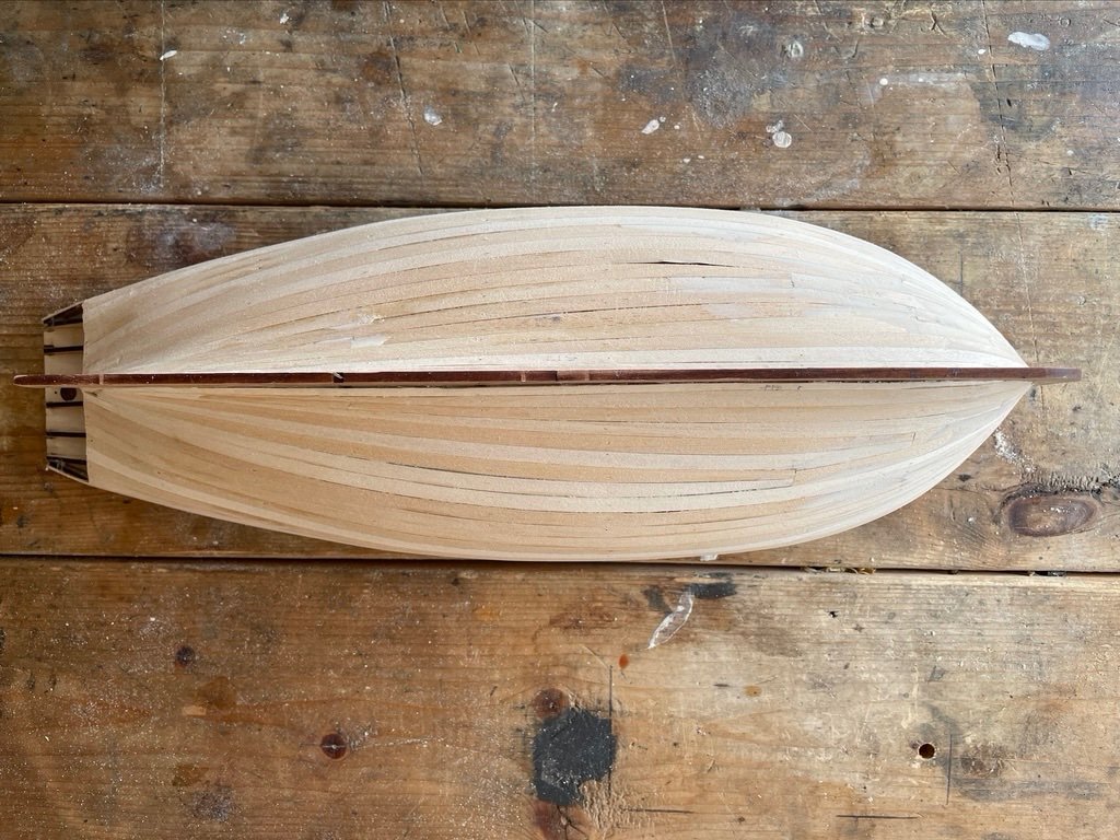
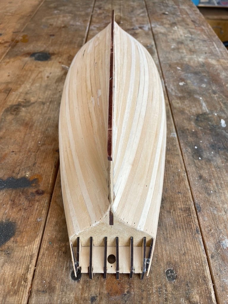
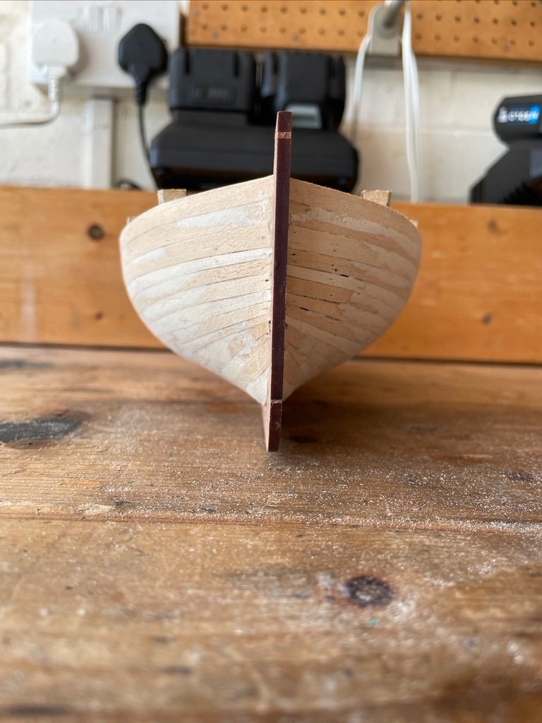
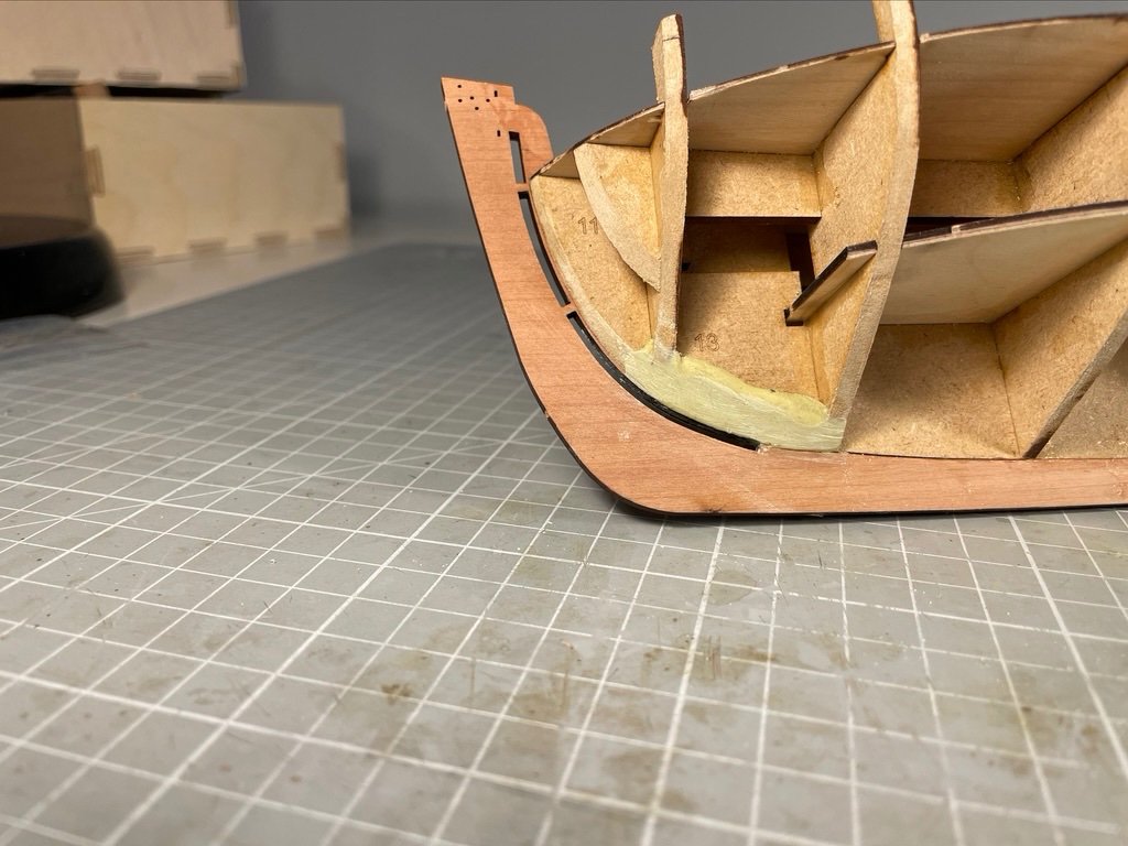
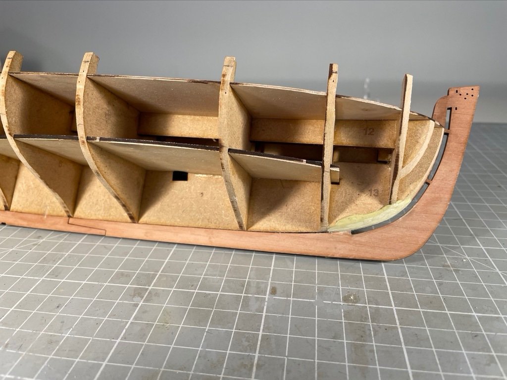
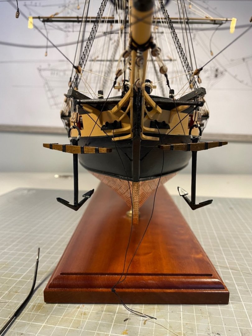
It's been a while. But I have some progress to share after a fantastic late summer of travel and cycling (sometimes combined!) Anyway, I've finished the second planking (give or take a rub-down with some 320 grit, and another coat of varnish). I set myself the challenge of getting a respectable result with no soaking/heating of the pear strip wood, or use of pins. The test being: would I be will just to varnish the hull, and not paint most of it (though I do plan to paint her)? I followed the usual advice and divided the hull into three zones - two initially and then a third - built myself a spreadsheet and shaped the planks as I went. I find shaping the planks with a knife and a ruler very hit and miss so instead marked up the cut lines and then held them in a plank clamp with the cut lines aligned with the tops of the jaws. I then simply planed off the waste - typically at the forward end and at the aft. I could clamp 6 strips together so shaping was relatively quick (once I got the hang of it). I chamfered each plank on one edge by mounting the strip in the clamp and then inclining the plane. Annoyingly I forgot to do this bit for the first few planks. Holding the planks in place while the CA set was 80% trivial, 10% challenging and 10% near impossible. Got better at it but future projects will require a bit of thought. For sanding the hull, I started with 80 grit paper using a set of Occre sanders. Slow process. I happened to be in B&Q and saw they had Black and Decker "Mouse" palm sanders for £11!! I recalled @James H saying that @chris watton had talked him into buying a palm sander, so thought I could risk £11 on (yet another) power tool. It was transformational! Particualrly after I had finished the first cut and then applied a small amount of acrylic filler - which, as I have said before, sets rock hard. After that second sanding at 80, I went up through the girts to 240 just using the Occre tools. And here she is after that sanding I struggled to get the planks to fit well at the prow and the stern. Almost inevitably getting a good fit at the prow and then cutting them short at the stern. If you zoom in on the last pic, above, there's quite a lot of filler on show. A rather greater challenge arose with the top planks at the stern. They are essentially unsupported and one of them was not well attached to the first planking beneath. Some overzealous (hand) sanding knocked it loose. A little very thin CA reattached it, and I then put in a bracing strut, visible athwartships at the stern here, that I will remove shortly. While sanding I noticed the familiar protruding-plank-that-doesn't-sand-down. That is, a plank not attached to the 1st planking beneath it. Fortunately I noticed this before I sanded it through and could anchor it using the very thin CA again. Turns out that there was a handful of such defects, all on the port side. Perhaps I held the planks differently on port and starboard sides while gluing them And so here she is with one coat of varnish applied And so would I be willing to display this varnished and unpainted? No, not quite. There are two flaws that annoy me but I could live with : first, and most annoyingly , not bevelling some of the upper planks, resulted in some noticeable gaps between planks (filled with CA and so not now fillable) and second, the lay of some of the planks is not quite as natural as would be desired. But the real killer is that I needed to colour the filler and made the rookie error of matching that colour to dry, unvarnished planks. As the aft view shows, that's not great. But when all is said and done, I'm pleased with the overall job.


- 34 replies
-
- 11
-

-
- Alert
- Vanguard Models
- (and 1 more)
-
By an extraordinary coincidence, I finished the second planking on Alert today. So I can say with fresh expeience under my belt - well done. That's a neat job!
-
I will follow with interest, Andrew. We are both doing VM cutters and both intending to add sails! Enjoy your holiday. Mike
-
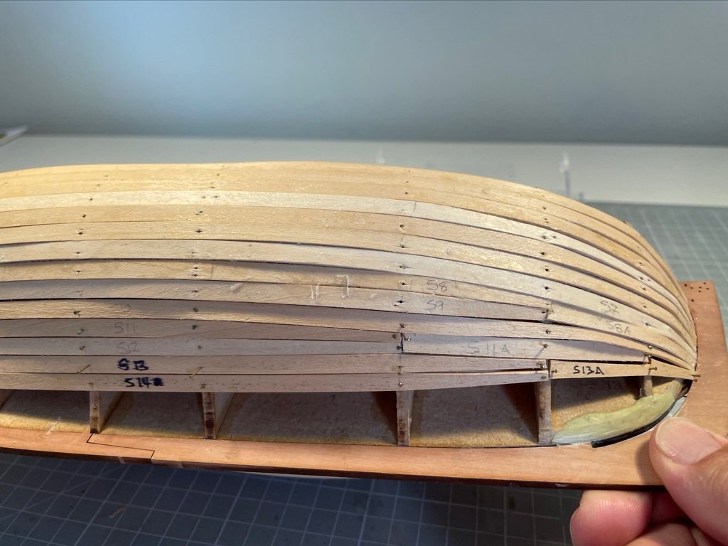
I undertook the 1st planking with medium care. Planks were soaked in water, for 4+ hours, roughly trimmed and then pinned in place while wet. After drying overnight they were removed and then glued and pinned in place. I typically did 3 or 4 planks to starboard and to port, at a sitting The end result, prior to filling and sanding, was a little rough, but well-within acceptable bounds, I thought. I had only intended to use a little filler, but the nozzle on the tube was blocked, so I slit it open and then had mountains to use or throw away. I've lived in Yorkshire too long to throw anything away, so I thought: more must be better. It's not! Acrylic filler sets rock hard, so sanding it down is a pain. It takes a long time and it's easy to sand off timber and leave filler behind. So it was out to the garage where there's an abundance of power tools. Just about avoided sanding off too much timber - but it's close!
- 34 replies
-
- 6
-
-
- Alert
- Vanguard Models
- (and 1 more)
-
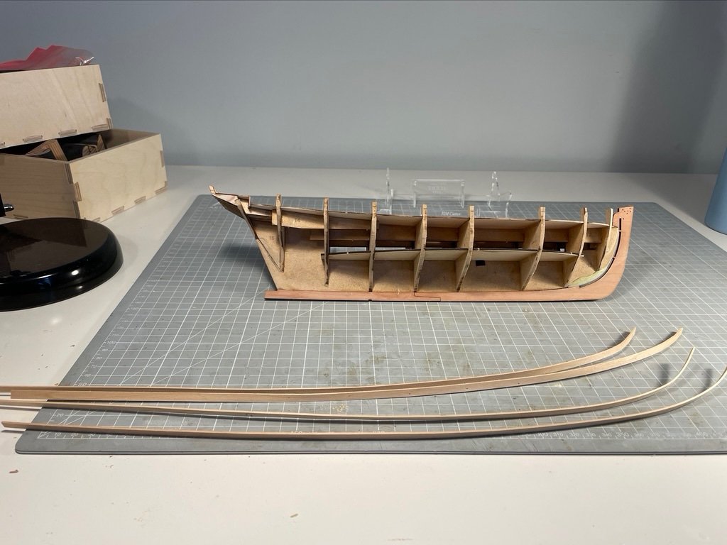
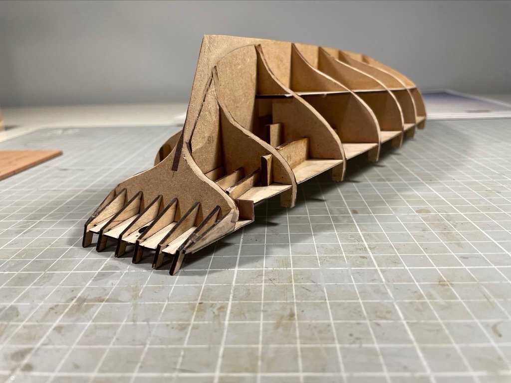
So, to progress. High-quality kit design and documentation mean that the last couple of weeks have been pretty smooth sailing. The odd bit of sunshine means that modelling has not been top priority, and my capacity to rush at things means there have been one or two minor issues My warm feelings towards MDF bulkheads have grown: sanding them down takes minutes, not hours and simple hand tools are more than sufficient. Here are the end results However, I should have dry-fitted the keelson before ploughing on, and then I would have seen where the bearding line was with a little more precision. Never mind, a small amount of Milliput meant that I could put back what over-zealous sanding had removed. So ready for first planking.
- 34 replies
-
- 3
-
-
- Alert
- Vanguard Models
- (and 1 more)
-
Thanks Andrew. I just saw your Trial log when I opened MSW - will go back and have a look when I've finished posting here.
- 34 replies
-
- 1
-
-
- Alert
- Vanguard Models
- (and 1 more)
-
Welcome! Lake Constance is a fabulous place . A friend and I did the bike ride around it the summer before Covid - fabulous scenery, villages and food. Some beer too. Really sorry to hear you have had the long version, but given time, you will get better. And in the meantime - build models! I'm and engineer, too, and I had a great time working on my Snake model - plenty of geometry to do, especially after I bought a Proxxon milling machine! Cheers MIke
-
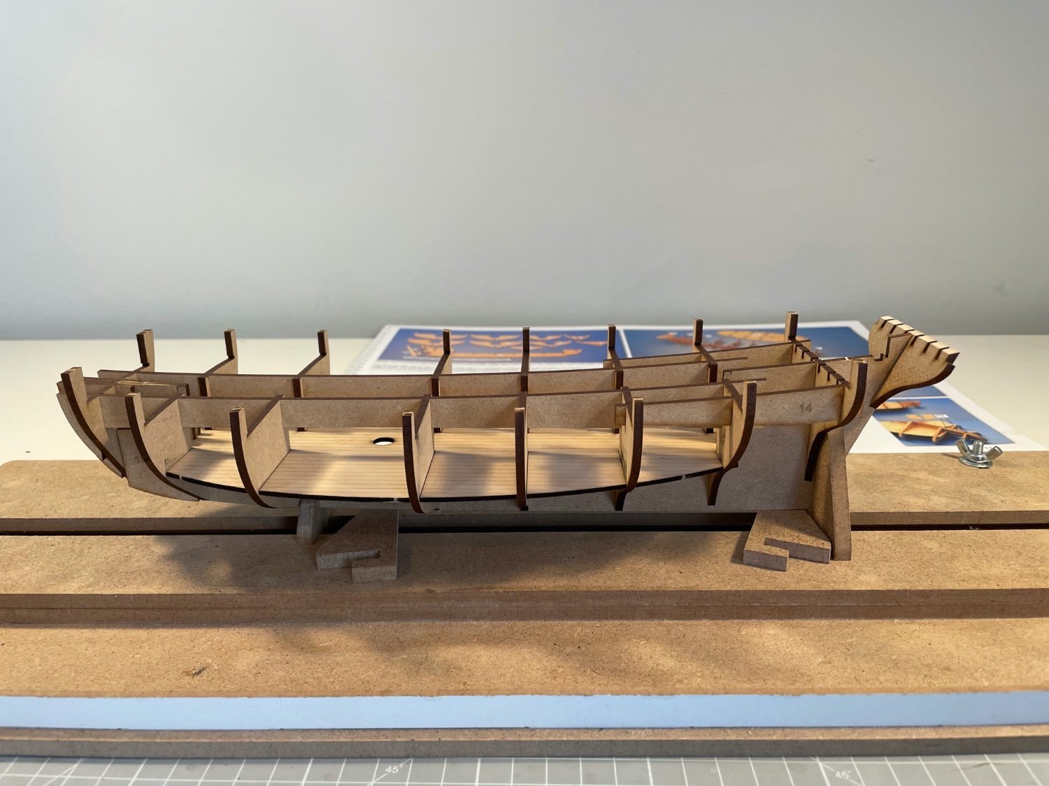
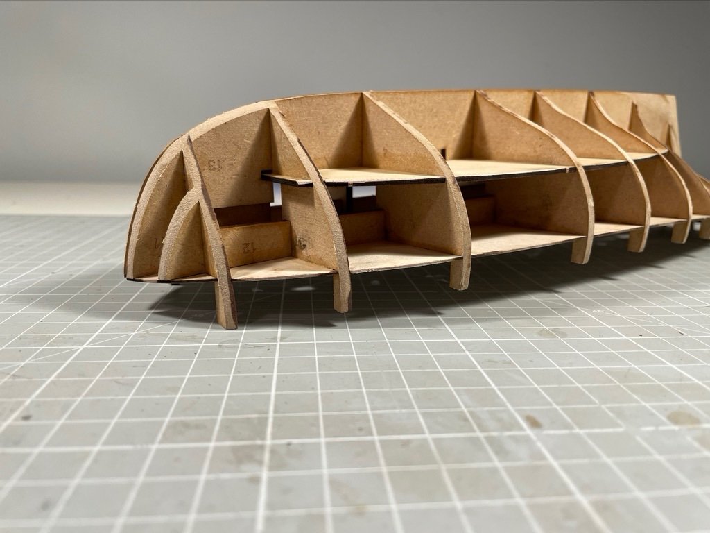
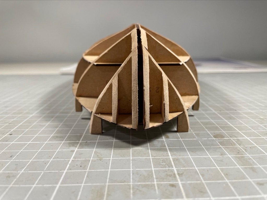
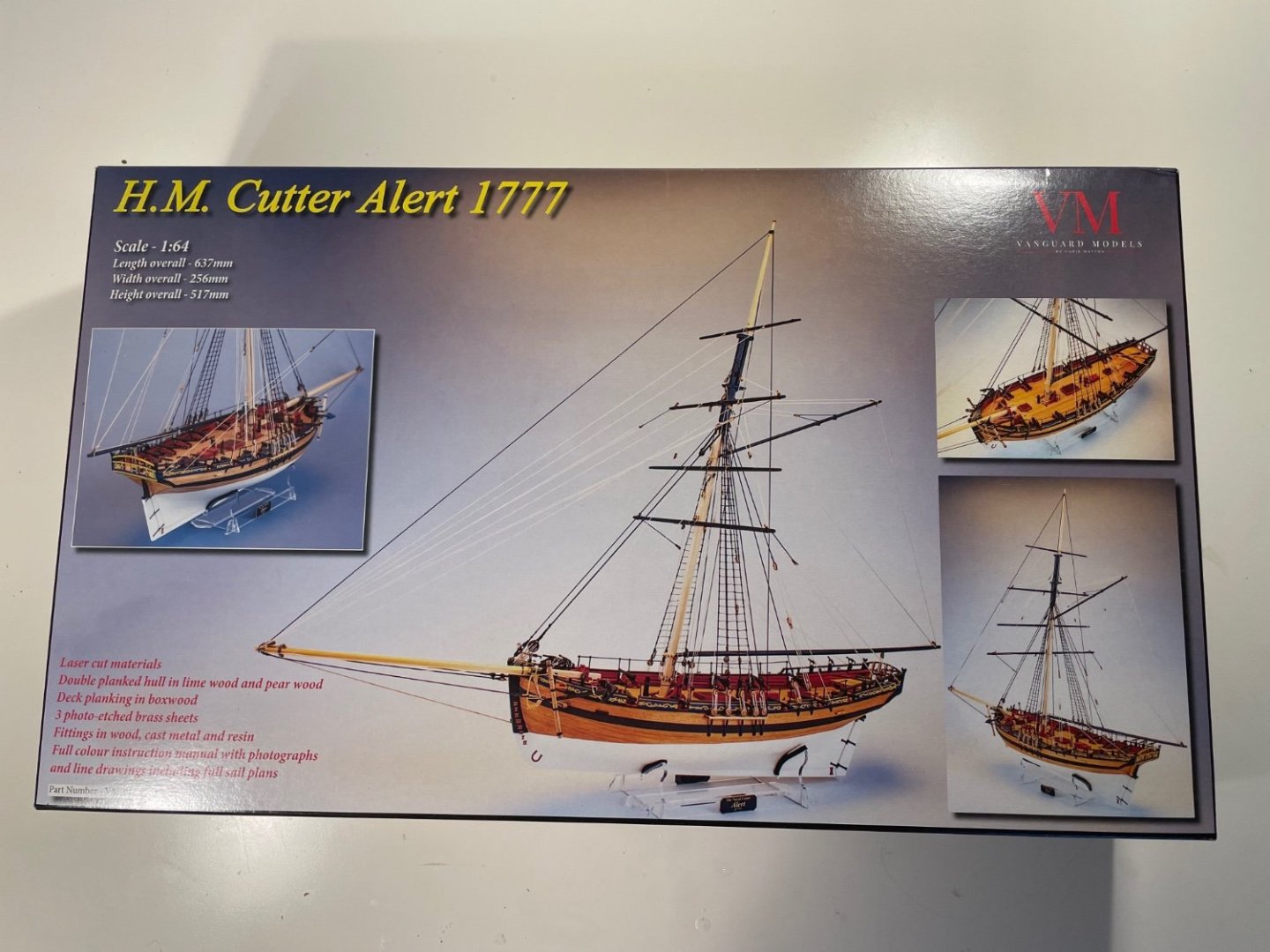
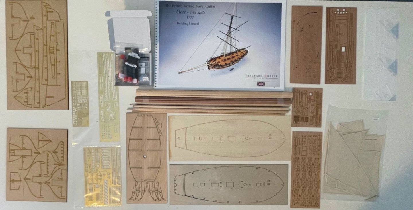
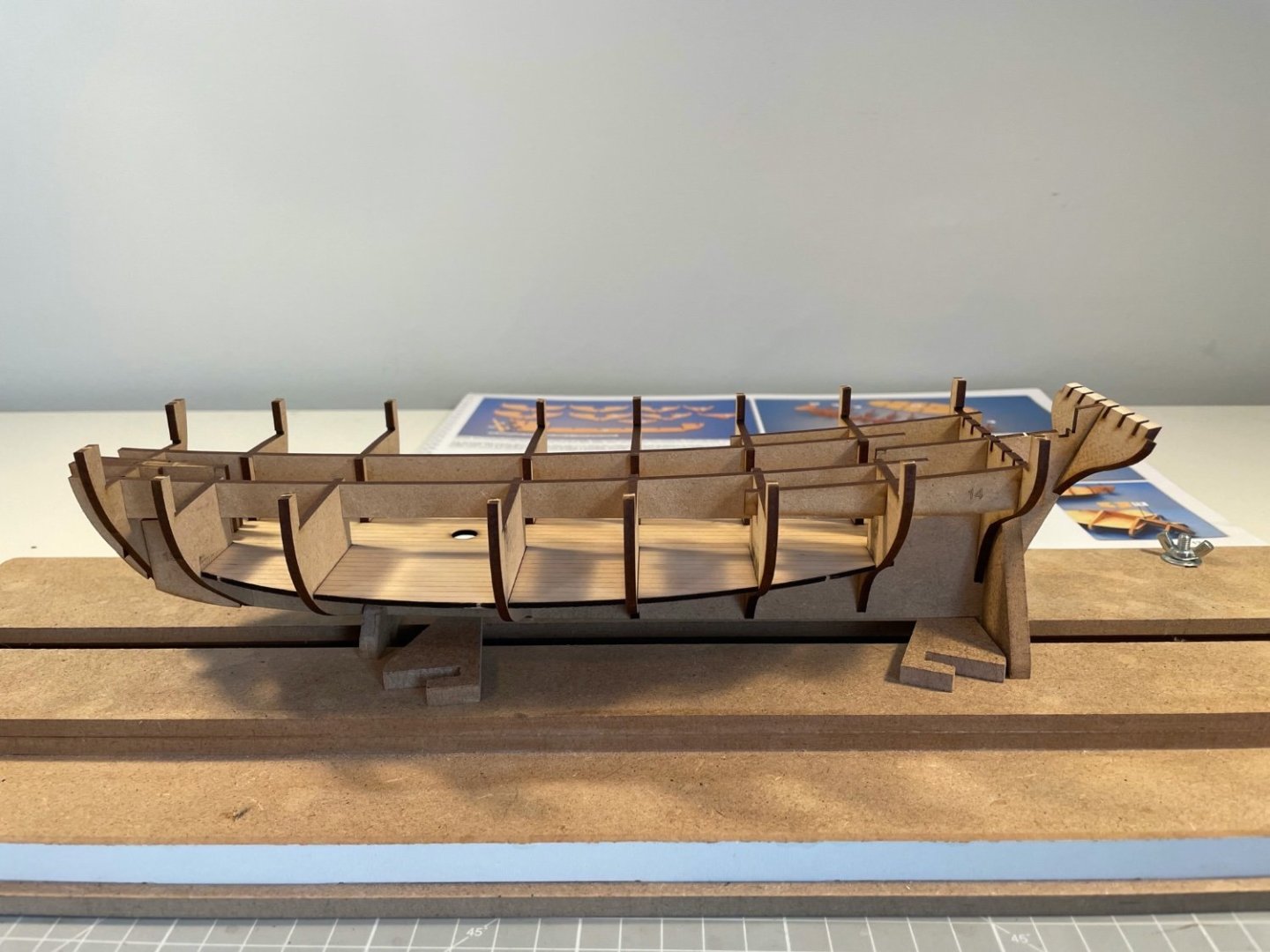
Box looks lovely, though hard to photograph! Contents even better. I'm particularly struck by the quantity and quality of materials that add embellishment. The hull is modest in scale, the rig fairly simple, but the fittings, and in particular the photo-etched brass, are a joy to behold. But to building! First, I should say I'm an instant convert to MDF and laser cutting. The bulkheads and false keel are very easy to separate from their frame, and slot together very neatly. There's a bit of give, so had I followed he instructions and glued those as a first step, quite a lot of clamping would be needed. But I didn't. I carried on and dry assembled until I had this: Which is so thoroughly braced that it is essentially rigid and square. I didn't attach the stern frames (though I should have). I also didn't do any sanding other than of bulkhead 10 - Dremel and I will go outside next week. I then painted diluted PVA (3:1 glue:water) around all the joints. A real joy to benefit from such accurately machined parts and such clever design.
- 34 replies
-
- 10
-
-
- Alert
- Vanguard Models
- (and 1 more)
-
Thanks - I am. I was just looking at your Log. The index in your first post will be very useful!
- 34 replies
-
- 4
-
-
- Alert
- Vanguard Models
- (and 1 more)
-
This is my third build, and while I really do want to build a frigate, it suits me to have a smaller project first. I'm also keen to have a go at a modern Chris Watton design, and since Alert is numbered VM 1, there's nothing like starting at the beginning. Particularly as I get the benefit of doing the updated version 3. And free sails. Because, yes, I'm going to rig sails. I doubt this Log will be anything like as verbose as my Snake. Mainly because I doubt I'll have the same level of problem solving to do, or the same amount of steam to let off over the poverty of the instructions. And there-in lies a deeper reason - anyone can read Chris's magnificent instruction manual online - for free. So I hardly need to spell-out what I'm doing. It's also true that there are some fine, detailed Logs already on MSW. You can find a list, here
- 34 replies
-
- 3
-
-
- Alert
- Vanguard Models
- (and 1 more)
-
Thank goodness! And on your full list, delighted to see Anson's Centurion. If you ever tire of 1:64 and 17/18/19th C warships, I'd give a vote for some of the 19th C packets, clippers and windjammers. I was at a market in Hobart Tas, last Feb, and a fellow, name of Brian Stafford, had a stall selling his self-published The Great Windships - very interesting books on the development of merchant sailing ships. Prompted me to re-read The Last Grain Race by Eric Newby. Newby sailed in, and Stafford extols, the windjammers - the last important commercial sailing ships - fantastic vessels. But they were big. Up to 7 masts and over 100 m in length (probably excluding the bowsprit). So that's 1.5-2 m at 1:64. But anyway, Suprise and Centurion will do me for a while. And that's after Alert. Whose build log I must now start.
-
Tilting mount for Proxxon Vise for MF70
Mike_H replied to ChrisLBren's topic in Modeling tools and Workshop Equipment
Thanks Mark - belated, I know. Been travelling, then gardening and cycling. About to get back to some model making. Mike -
And more than 2 year's later, more thanks and congratulations on your build and your log. Just as you built Alert waiting for Sphinx, I had planned one of Vanguard's fishing boats while waiting for Surprise. Surprise is delayed so I will use Alert to fill a slightly longer gap and since I only model build when the weather keeps me indoors, she should do the trick. Your log will act as a running commentary on what to be thinking about at each stage, and your build as a beacon of success. So thanks - and I expect you will hear from me (keeping it all within Yorkshire) Mike
- 160 replies
-
- 4
-
-

-
- Alert
- vanguard models
- (and 1 more)
-
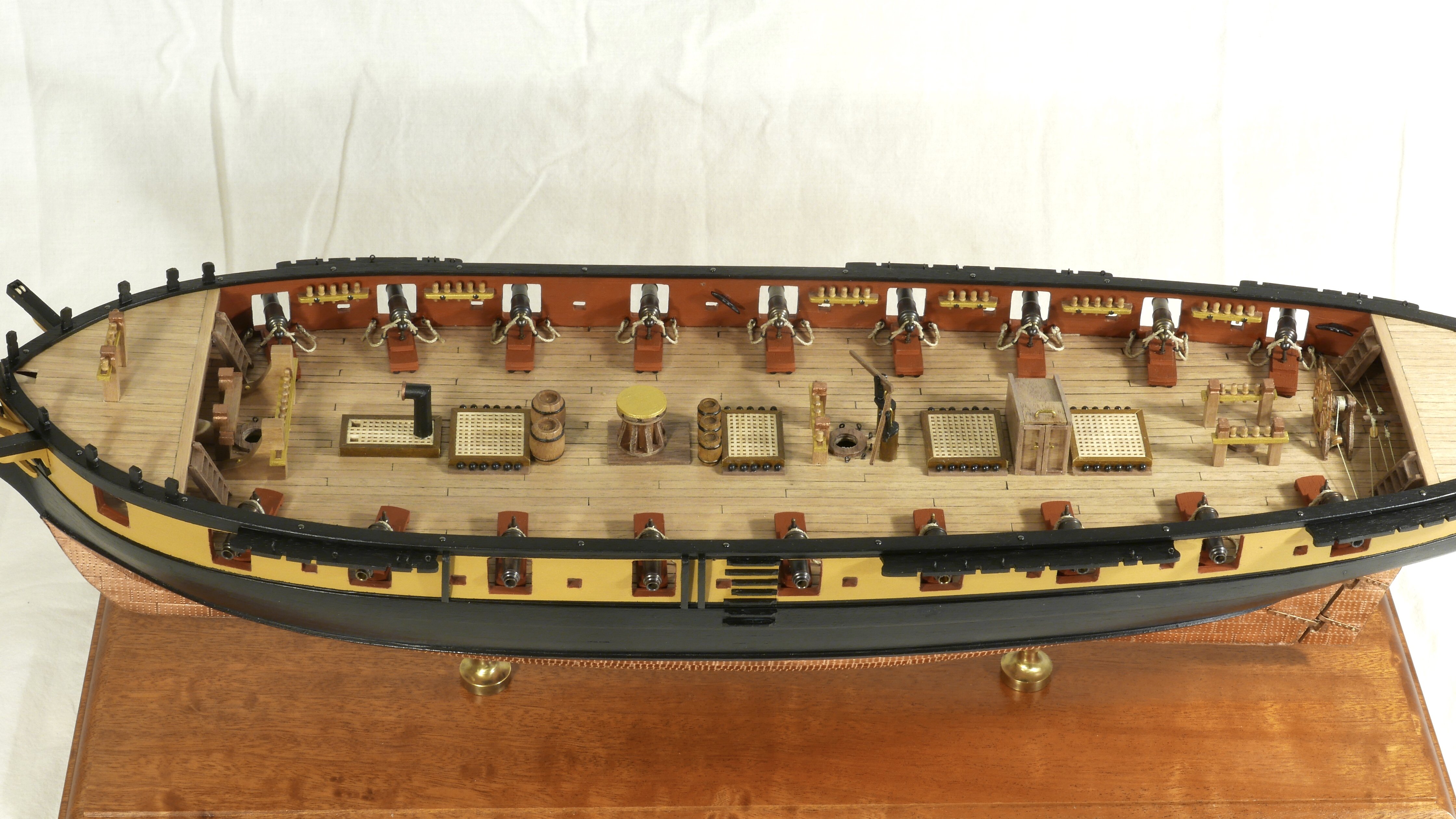
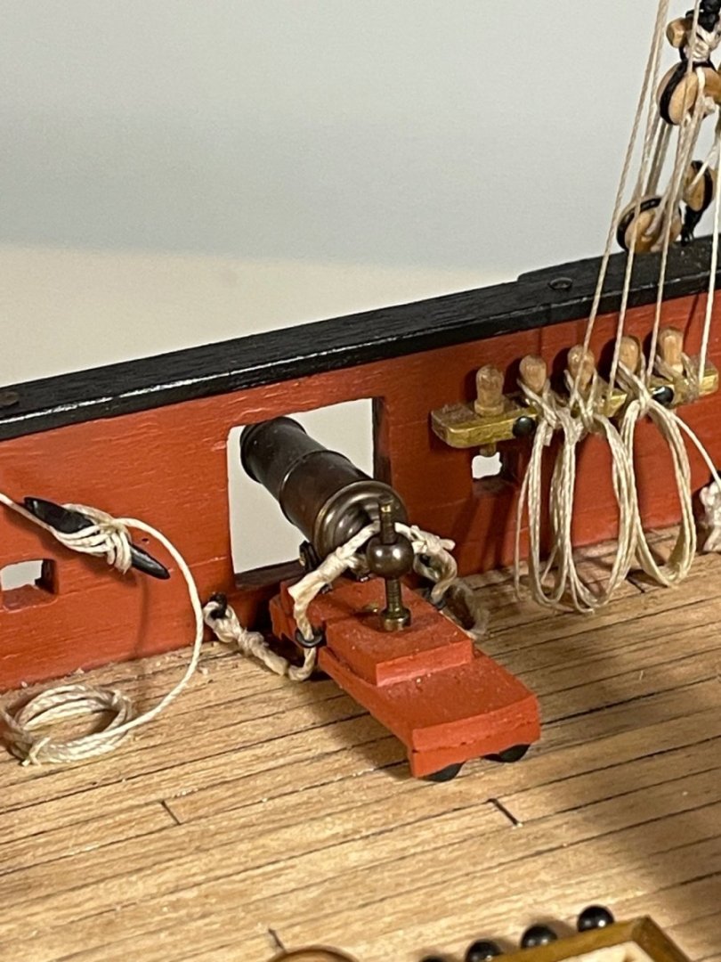
Ah yes. The brass gun barrels are pretty good (if your kit had those, not the white metal) but the other parts are pretty rudimentary and the assembled carriages will NOT sit on external porta. Great to see you back working on her.
-
Just catching up after a month of riding my bike in antipodean sunshine. She looks magnificent! Really striking how the final addition of deck furniture gives a sense of scale - she’s a big girl. And also how it shouts out about the quality of the model (and the build skills used). Every times I see the yellow ochre shown in this log I think - wow, that’s bright. Probably my only real point of comparison is Victory, and I know that historical views on her colour at Trafalgar have changed over time. Given how much research Chris has done, I wonder if there is a precedent for such a bright yellow? On documentation of masting and rigging, I think Chris’s twin points - decent drawings and the level of skill expected for this model - are compelling arguments. That said, and having just hauled myself up from novice-level in this respect, there is room for an intermediate model, where the manual suggests the order of build and gives a brief description of the purpose of each category of rigging.
- 488 replies
-
- 3
-
-
- Indefatigable
- Vanguard Models
- (and 1 more)
-
Hi Sjors Glad to see this - I’m an Aussie and actually in Australia at the moment. Mike
-
So glad I found this - as ever your determination shines through. Mike
-
Hi Sjors, great to see you finished her - and that she looks so sharp. I was worried that you had run out of steam (wind?) as so many Snake builders do. Good luck with your other projects - I’m going to follow them in a minute.
- 53 replies
-
- 1
-
-
- brig-sloop
- Caldercraft
- (and 2 more)
-
As ever a model of patience, with a result that oozes class. Beautiful to see.
-
Very interesting. The absence of a figure-head is a real surprise.
-
Now this is very exciting news. Time for some serious conversations.
- 488 replies
-
- 3
-
-

-
- Indefatigable
- Vanguard Models
- (and 1 more)
-
Tilting mount for Proxxon Vise for MF70
Mike_H replied to ChrisLBren's topic in Modeling tools and Workshop Equipment
Hi Mark, can you give link to this part, or perhaps a part number? cheers Mike -
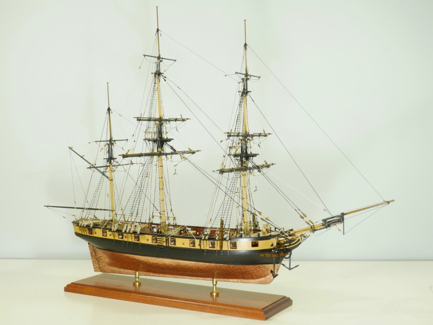
And yes, my Snake is FINISHED!. There are some tings I could fix - though I won't - and I will build a display case, but that is it! I have created a (large) album of photographs of the finished article, you can find here. And show just a few below: I am more than delighted by the finished article - in fact truly amazed. All it took was patience and a willingness (very reluctantly) to see small advances as proper staging posts. And if I were to offer anyone as green as I was a piece of advice it would be just that - take time to recognise an achievement, and enjoy it. Which is a segway to another piece of advice (only one more after this): use Model Ship World! Use it because it's full of advice, encouragement and experience. But use it because it's a place that you can mark your (small) achievements. And the final piece of advice? Something about skills. It was going to be about CA glue (use tiny drops), but on reflection the most important skillI acquired and used hundreds, perhaps even thousands, of times was this gem about how to seize or whip a rope. Finally the best, or perhaps happiest, piece of advice I received was to get hold of a copy of Modelling the brig of war "Irene" by E.W. Petrejus. It is not only a beautiful book about a very similar vessel, but displays a depth of appreciation for such a vessel that I now find I have myself A few words on the kit. On the whole it's very good. I found the materials very good most of the time, and the design convincing with lots of detail. The plans varied from excellent to fair, and in fact the only real criticism I would have would be about the instructions - they were worse than poor - risible would be a better description. In scope I think this is essentially a challenging build for a relative new comer, but the absence of instructions makes it much harder. I'm glad in retrospect that I self-educated myself through the weeks and months of challenges, but for quite a lot of that time I felt distinctly bitter that just a few sentences of guidance would have made life much nicer. So my words of caution would be: you will need many skills, and quite a bit of knowledge; your'e on your own there. But somehow, the whole thing is more, and better than, the sum of its parts. I have a profound appreciation of the business-like lines of the hull, the crowded war-like deck, and the absence of ornamentation. This was a working, fierce small ship. Yet above that nearly brutal gun platform towers a pyramid of slender spars and silk-like ropes to create a thing of beauty and a article of mechanical near perfection. I probably spent about 1000 hours bringing forth this glory - it was worth every one of them. So what next? I do not know - something small. Or large? Something more modern, or not. Something military or commercial. But something! With that, thanks for your company. See you again.

- 109 replies
-
- 11
-
-
-
- snake
- caldercraft
- (and 1 more)
-
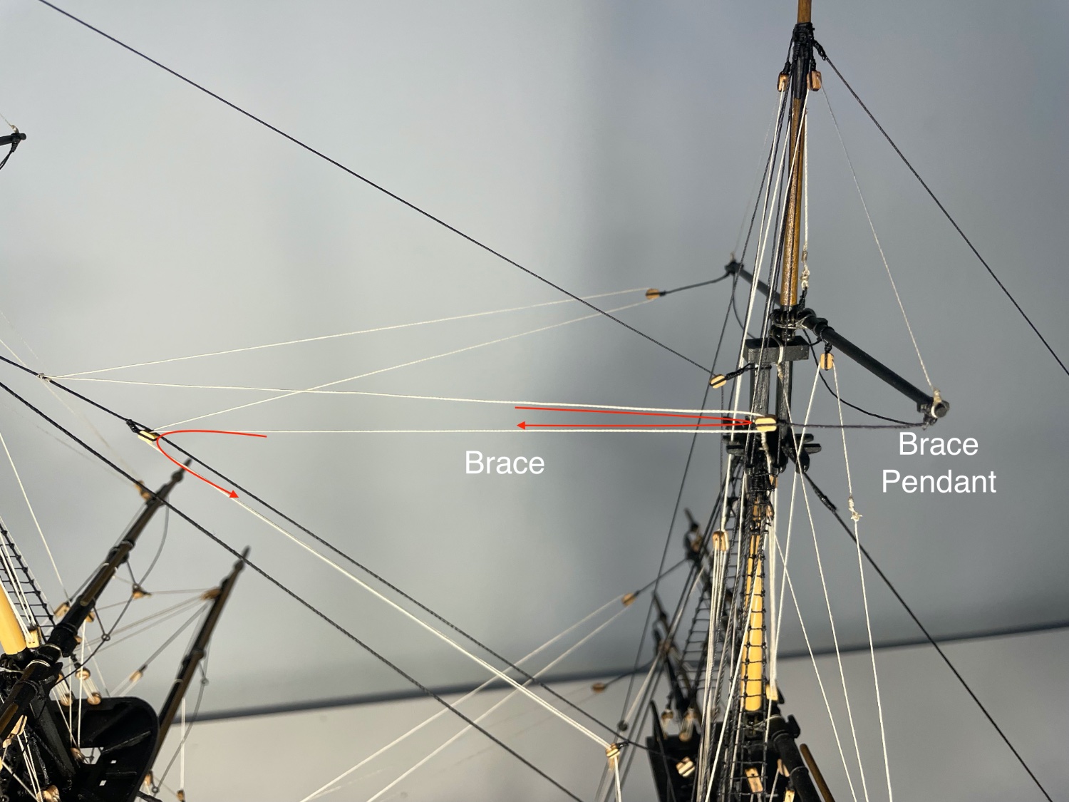
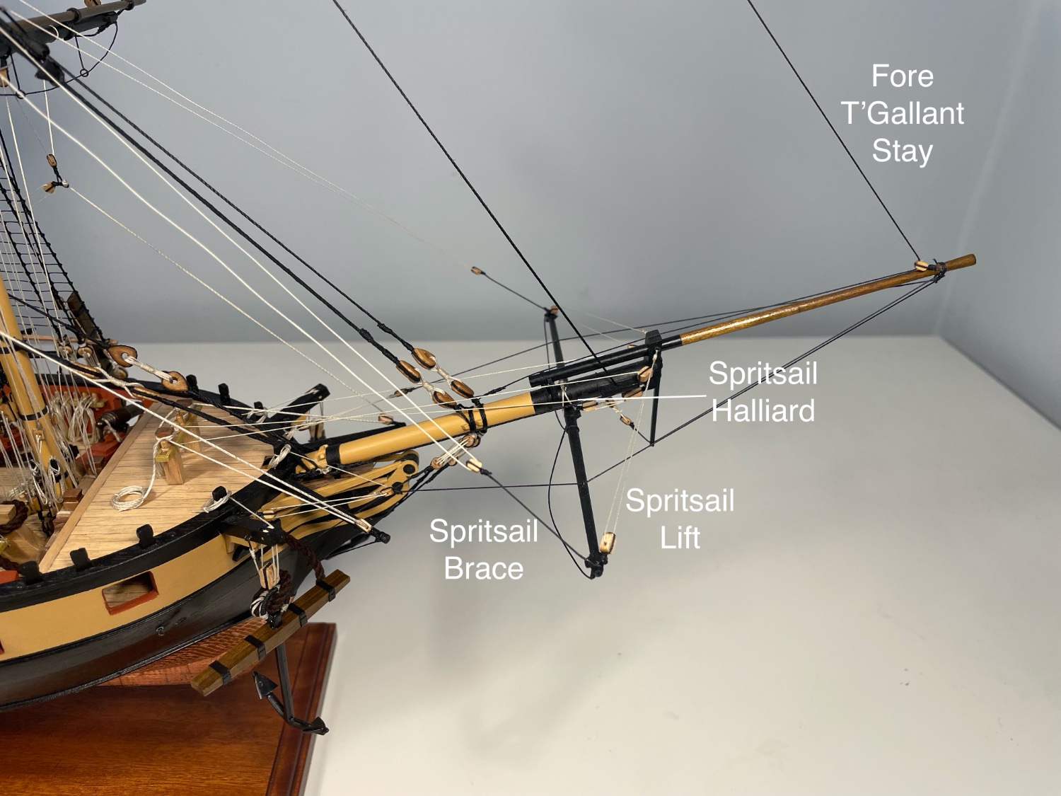
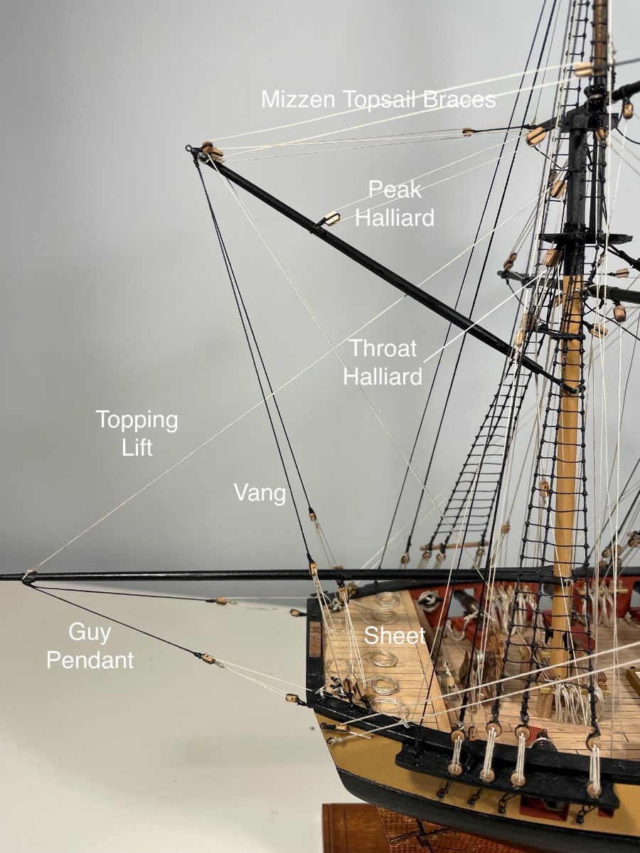
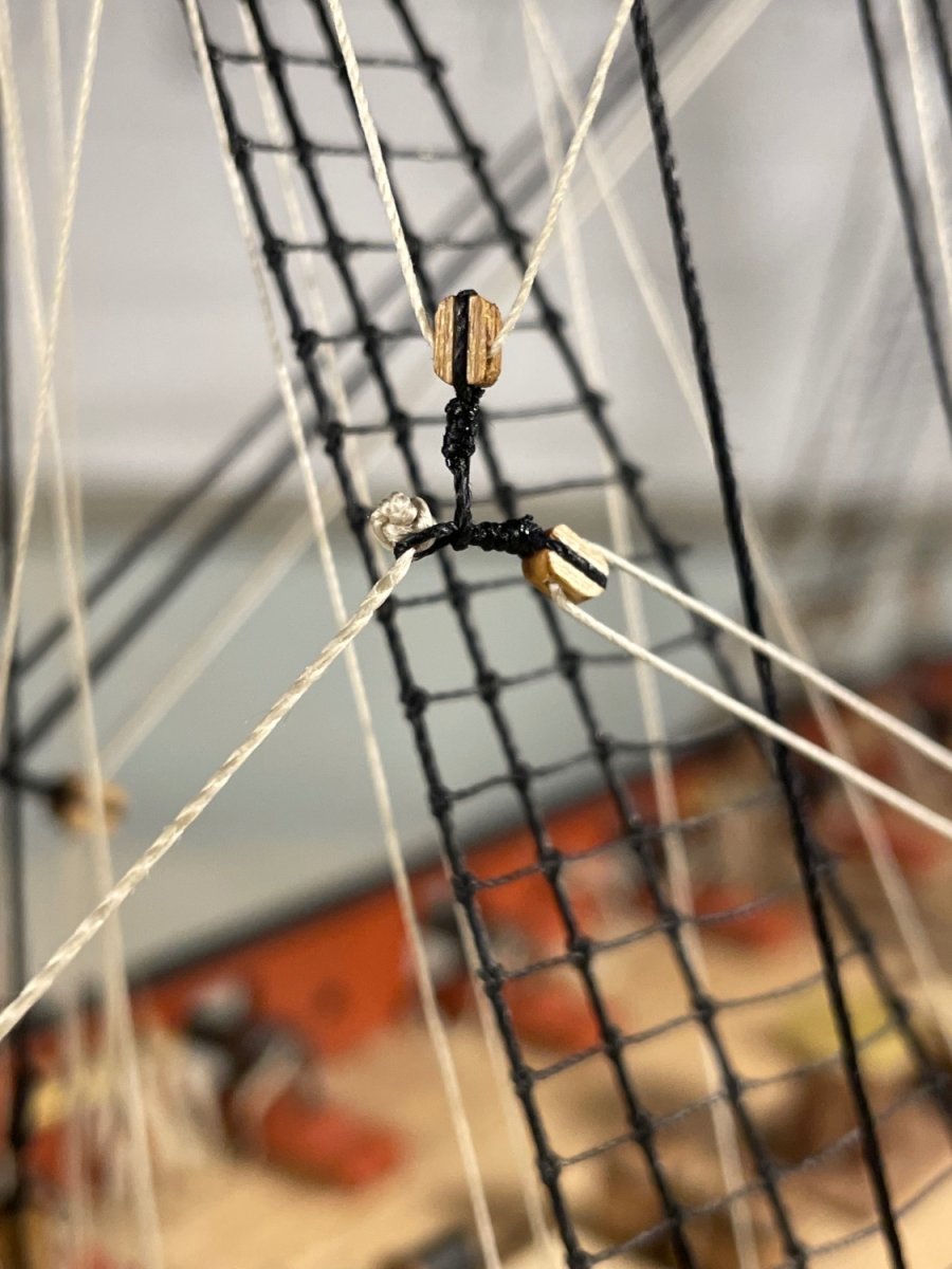
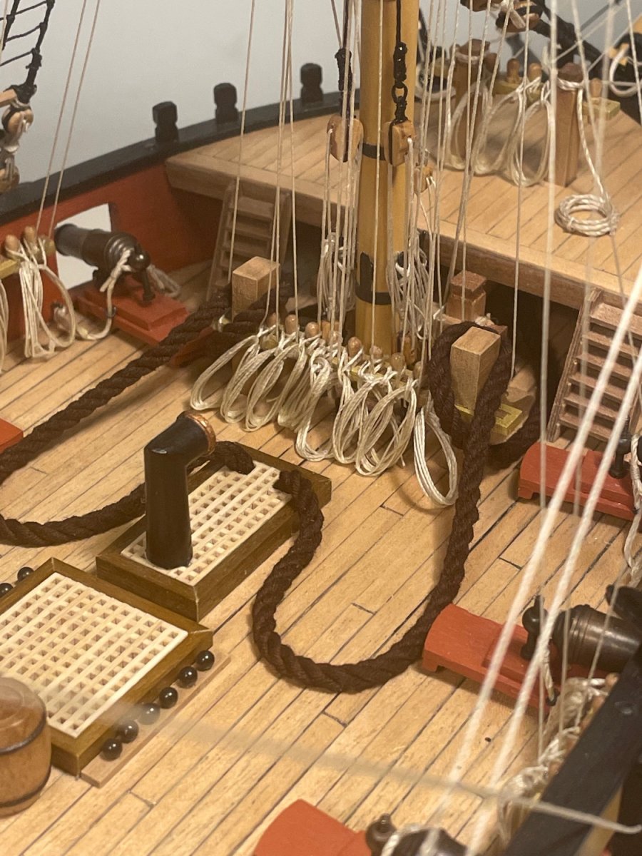
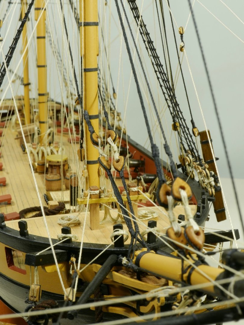
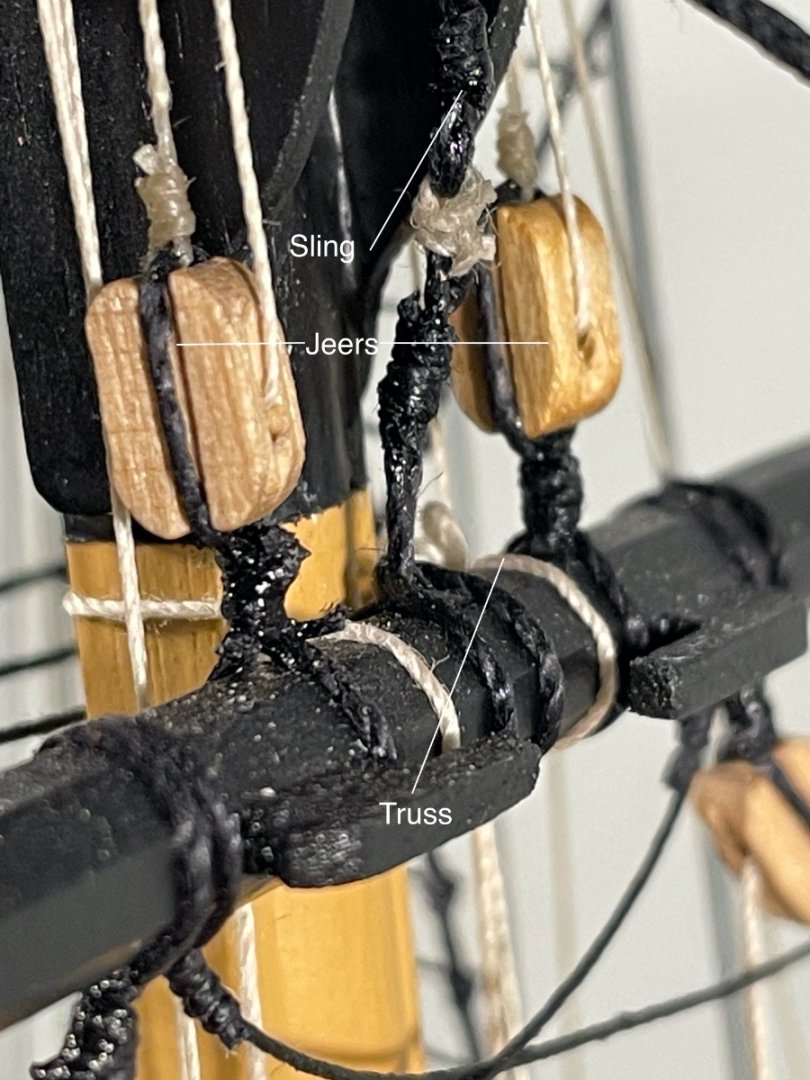
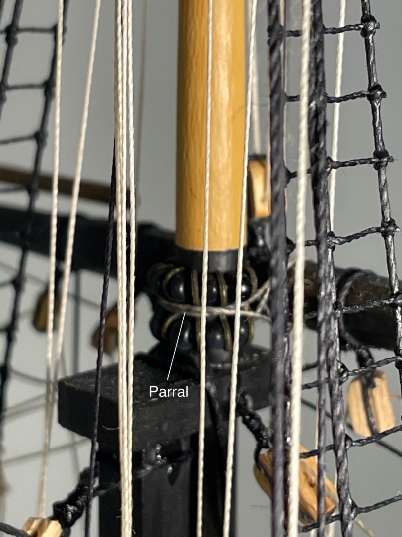
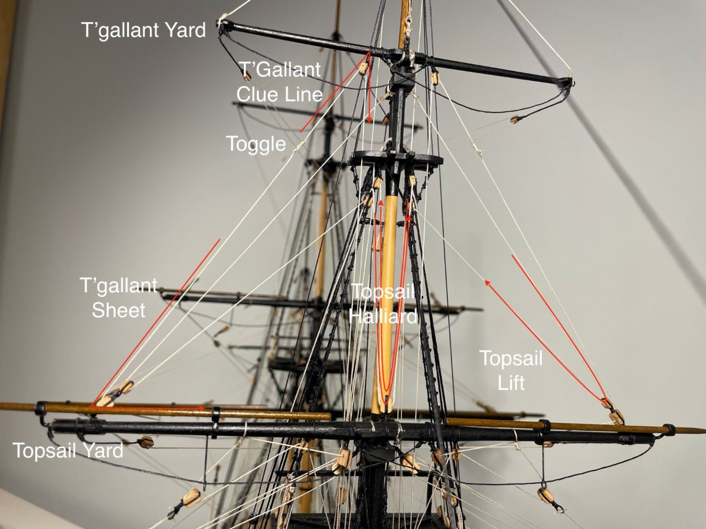
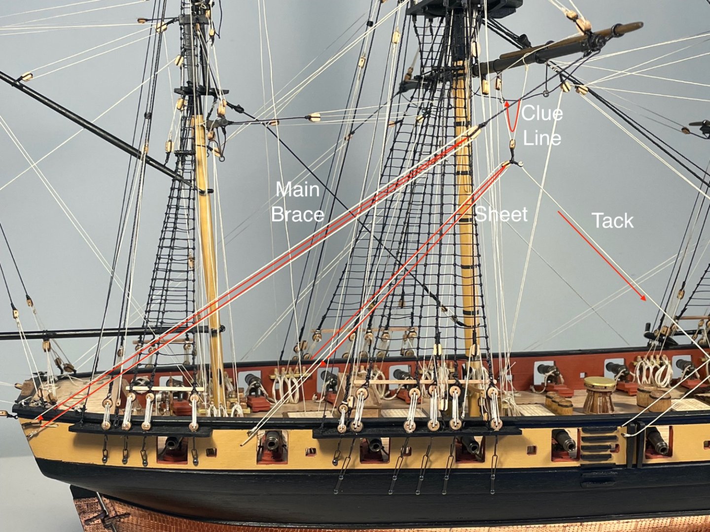
Rigging This has been quite a journey, for much of which I felt quite lost. It was only towards the end that, to carry on with the metaphor, I could see the wood for the trees, and understood where I was going. The kit plans show pretty much all the rigging that needs to be added, identify the blocks (with about 95% accuracy) and numbers the belaying points (nearly all of them). But what was missing was a narrative e.g what are all these lines for? It was only when I worked that out, that I understood what I was doing. It should be said, though, that I only think I understand. If you think I might not quite, please do comment and say so. I and any readers would be very grateful. Essential in this process of discovery was Lennath Petersson’s Rigging Period Ship Models. It shows exactly how a particular three-masted, square-rigged ship, the Melampus of 1785, was rigged. Snake is both younger by 12 years and smaller, but Petersson’s rigging plan matches those provided with the kit, so well, that I suspect that is no coincidence. But even so, I had to create my own narrative before I felt that I knew what I was doing. I have used Petersson’s naming and spellings, and also opted to capitalise most rigging-specific names, essentially for clarity, if not grammatical correctness. When I started this build log, I claimed that “ I plan to show other novices the process of climbing the learning curve” I cannot say that for the last 6 months I have been a good guide, but I will now attempt to record my rigging narrative. The standing rigging is, I think pretty self-explanatory. The shrouds support the masts laterally, and to an extent fore and aft towards the stern, the stays support fore-and aft either towards the bow, or in the case of back-stays, towards the stern. The standing rigging around the bowsprit creates a set of triangles or diamonds to give both lateral and vertical (downwards) support. Moving on to the less obvious, but things I think I knew. The lower yards (Fore, Main and Cross Jack) are not intended to be raised or lowered in normal use, though the upper – topsail and topgallant – are. Not all the running rigging is present, since there are no sails The sails, were they present hang from their respective yards and are secured to the yard beneath them (but wait!) Two crucial things that I could have known but didn’t seem to Two of the lines that are shown for all the square sails, the Sheets and the Clue Lines, would normally be secured to the lower corners of the sails (the Clues). Since there are no sails they cannot be! Instead they are secured to each other and hauled tight. The lower sails, while hanging from the lower yards, clearly cannot be secured to yet-lower yards. Instead a set of substantial lines running forward – the Tacks – are secured to the Clues so that the Sheets, Clue Lines and Tacks provide a triangle of forces. Once again, in these absence of sails, these three lines are joined. With that, the narrative for the square sails is straight forward. There are lines to: 1. Secure the yards to the mast and hold them aloft – Slings, Jeers, Trusses and Parrals The Slings are substantial loops of rope around the Fore and Main yards that in each case loop over the lower mast cap, holding the yards permanently aloft. The Jeers are substantial blocks with lines made fast on deck, used for raising the two largest spars. The three lower yards are made fast to their masts with Trusses with pendants brought down to deck. The yards are not intended to move vertically when the Trusses are hauled tight. Finally all of the upper yards are able to be raised and lowered so are attached to their masts with a kind of set of wheels (Trucks) held together by Ribs, to create a Parral. The Fore Yard, and Fore Topsail Yard 2. Raise and lower the yards, and square them up – Halliards and Lifts Each of the upper yards can be raised or lowered by hauling on one or two Halliards (belayed on deck) with suitable mechanical advantage via sets of blocks. The angle a yard makes to its mast is controlled by Lifts - lines extending from the mast above the highest point to which the yards can be raised, out to the ends of the yard. The Lfts also support the yard when the crew are working on it. Fore Topsail and Topgallant Yards 3. Rotate the yards – Braces In order for the square sails to catch the wind, the yards must be rotated – braced – in a horizontal plane. The Braces are long lines belayed on deck running to blocks which in turn are connected to the yard-ends by stout brace pendants. The Braces have a standing part frequently made fast to a stay. Fore Topgallant Brace 4. Set and reduce sail – Clue Lines, Sheets and Tacks Hauling on the Sheet pulls the corner (the Clue) of the sail down from the yard. For the upper yards, the Sheet runs from the deck where it is belayed, up to blocks on the yard beneath the sail, near the mast, and then out along that yard to blocks at the yard end and then up to the Clue. On the upper yards the Sheet pulls the Clue out to the end of the yard below. On the lower yards it pulls the Clue aft. Conversely the Clue Line hauls the Clue up to its yard thus largely taking the wind out of the sail (cue Jack Aubrey shouting “clew up! clew up” when Surprise is caught in a squall). The Clue line is belayed on deck, runs up to a block on the sail’s yard near the mast, and then diagonally down to the Clue. On the model, without sails, the Sheet and the Clue Line are joined by means of a loop and toggle (which is far from obvious on the plans). Finally the Tack is a heavy line that is coupled to the Clue Line and Sheet on the Fore and Main sails and then taken forward to the Boomkin for the Fore sail and near the Fore Chains for the Main. The couoling of the lines is very elegant with the Sheet and Clue blocks both being stropped with a loop: the loop from the Sheet passing through the loop from the Clue and the Tack passing through the loop from the Sheet. The Tack is prevented from pulling through by a large stylised Tack Knot. The Sheet runs directly aft. Main Brace, Sheet, Tack and Clue Line (see picture under 2. for upper yard lines) Bowsprit The running rigging provided on the bowsprit are the Spritsail Lift, The Spritsail Braces and the Spritsail Halliard, all playing much the same role as their equivalents on the yards (though in planes lifted up by 20º). The Spritsail Boom is made fast to the Bowsprit by a Truss. While not part of the running rigging, Fore Topgallant stay comes down to the end of the Jib Boom via a block at its outer extremity to be made fast on the Bowsprit. Bowsprit Running Rigging Spanker The Spanker, or the large fore and aft sail abaft the Mizzen, is well described in the kit’s plans, and is just like the gaff-rigged dinghies I sailed as a lad. But to name the parts, the Boom is equipped with a pair each of Sheets and Guy Pendants (one each to port and starboard, all belayed on the after-deck), and a Topping Lift taken from the outboard end of the Boom up to the Mizzen Masthead and then belayed via a purchase to the starboard aft Pinrail. The Gaff has a Peak Halliard running through two blocks to give a 3:1 purchase and belayed on deck. A pair of Vangs run from the outboard end of the Gaff to the afterdeck. Spanker Rigging Belaying The kit provides a numbered Belaying Plan with the numbers shown on the rigging diagrams. It’s not always easy to identify which number on the plan belongs to each line, and it’s absolutely impossible to look at the model and identify what each of the nearly 100 lines does. In the attached PDFs I have annotated the Belaying Plan with the names of the lines, and produced a list of all the Belaying Points with the Points named and numbered. Snake Belaying Plan.pdf Snake belaying points.pdf So that's what I think I know about rigging - do correct, advise and comment. And from these last two posts you might guess I'm pretty-well finished. Just a decent cleaning and then some final photographs I think!


- 109 replies
-
- 9
-
-
- snake
- caldercraft
- (and 1 more)
-
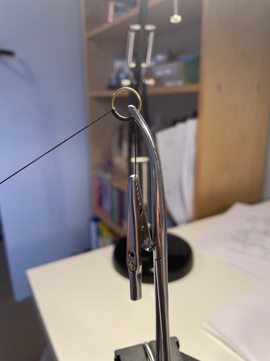
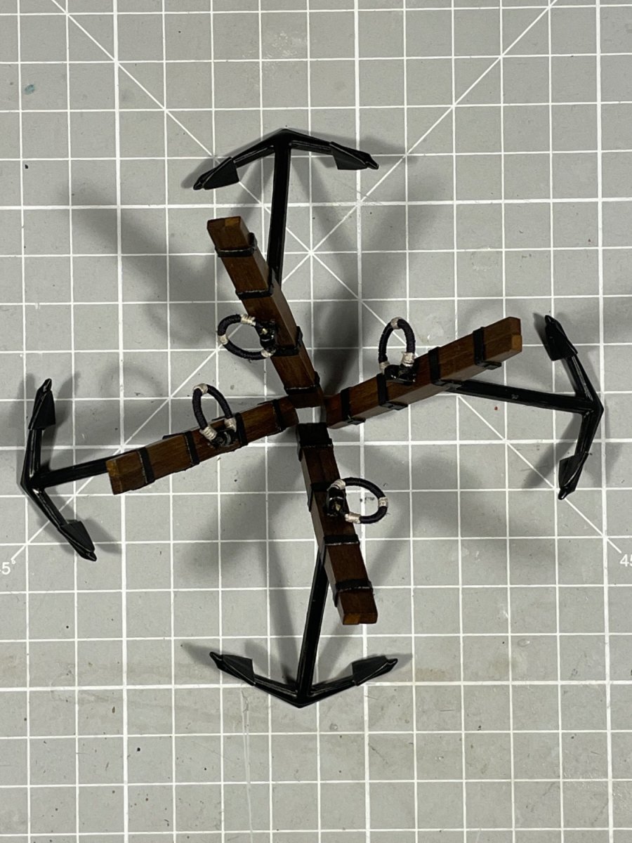
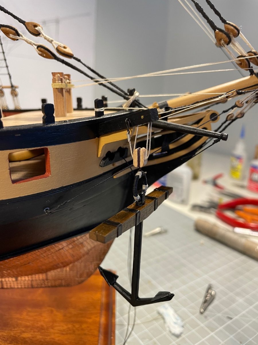
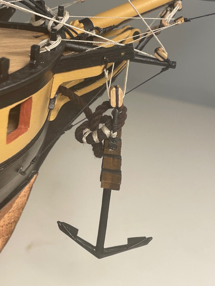
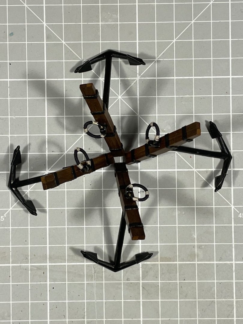
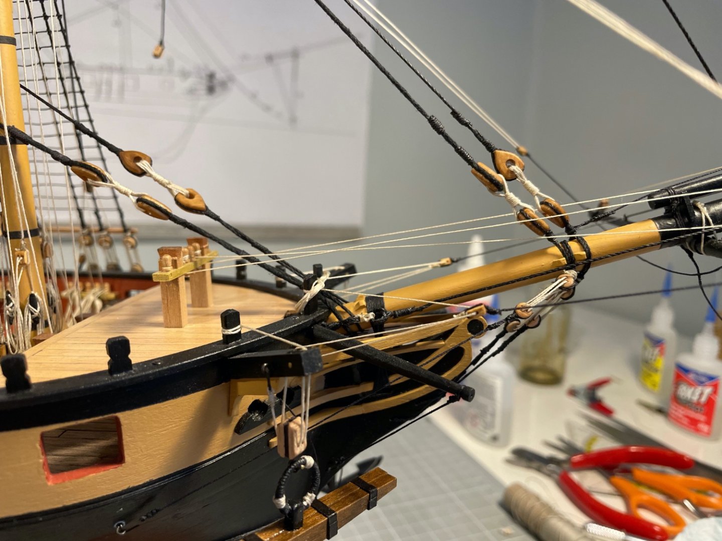
Just a brief update, before something much more exciting in a day or two. I've been rigging full time, but ran out of 0.5 mm thread (Jotika were fantastic and had two rolls with me in under 2 days, despite me giving them an expired credit card number). In the mean time I sorted out the anchors. I'd built up the anchors themselves some time back, and make brass rings by bending wire around a pice of dowel. First task was to apply the "metal" hoops on the stocks using the same technique of tack-then-glue that I used on the masts. Next was to pudden the rings which went much more quickly than expected. The ring was held in a pair of locking forceps which in turn were held in a small vice. The thread was tacked (to itself) with CA near the join in the ring and then just wound around. About every 90º I tacked the thread again. I then added some seizings and fitted the rings to the anchors The kit drawings suggest just binding the anchors to the rigging, but having out sheaves in the cathead I fancied catting, if not fishing two of them The effect is quite pleasing, if slightly unrealistic for a ship with no sails rigged. I might yet fish one or more of them, but no rush. {Edit} Here are both starboard anchors and an image of the cable newly dyed so as to look a little less pristine I also frapped (I think that is the term) the closed hearts on the fore stays And as to what is next - here's a sneak preview


- 109 replies
-
- 7
-
-
- snake
- caldercraft
- (and 1 more)