HOLIDAY DONATION DRIVE - SUPPORT MSW - DO YOUR PART TO KEEP THIS GREAT FORUM GOING! (Only 13 donations so far - C'mon guys!)
×

Mike_H
-
Posts
243 -
Joined
-
Last visited
Content Type
Profiles
Forums
Gallery
Events
Everything posted by Mike_H
-
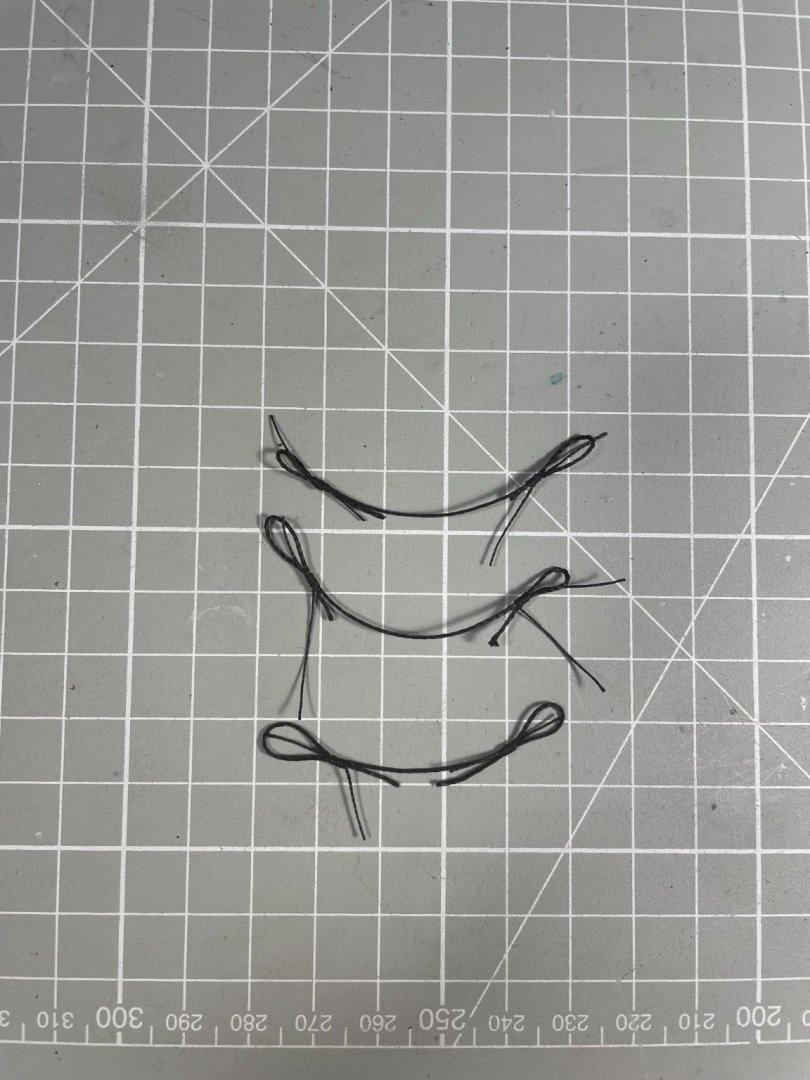
Interesting. My hanks are about 0.4 m in length, so about 25 m at scale. Having now done most of the running rigging, quite a lot of the lines are longer than that by a factor of two or three - once the rigging of blocks is taken account of - but most wouldn't have that length on the pins. Even so, I'm surprised at the number of coils shown in the hanks in your earlier pic. Better modelling thread is probably the answer
-
Well yes, but only if all are fully sheeted home. But since my Snake has yards in the lower position most lines will be at their maximum extension so the quantity of rope in the hanks will be much reduced.
- 109 replies
-
- 1
-

-
- snake
- caldercraft
- (and 1 more)
-
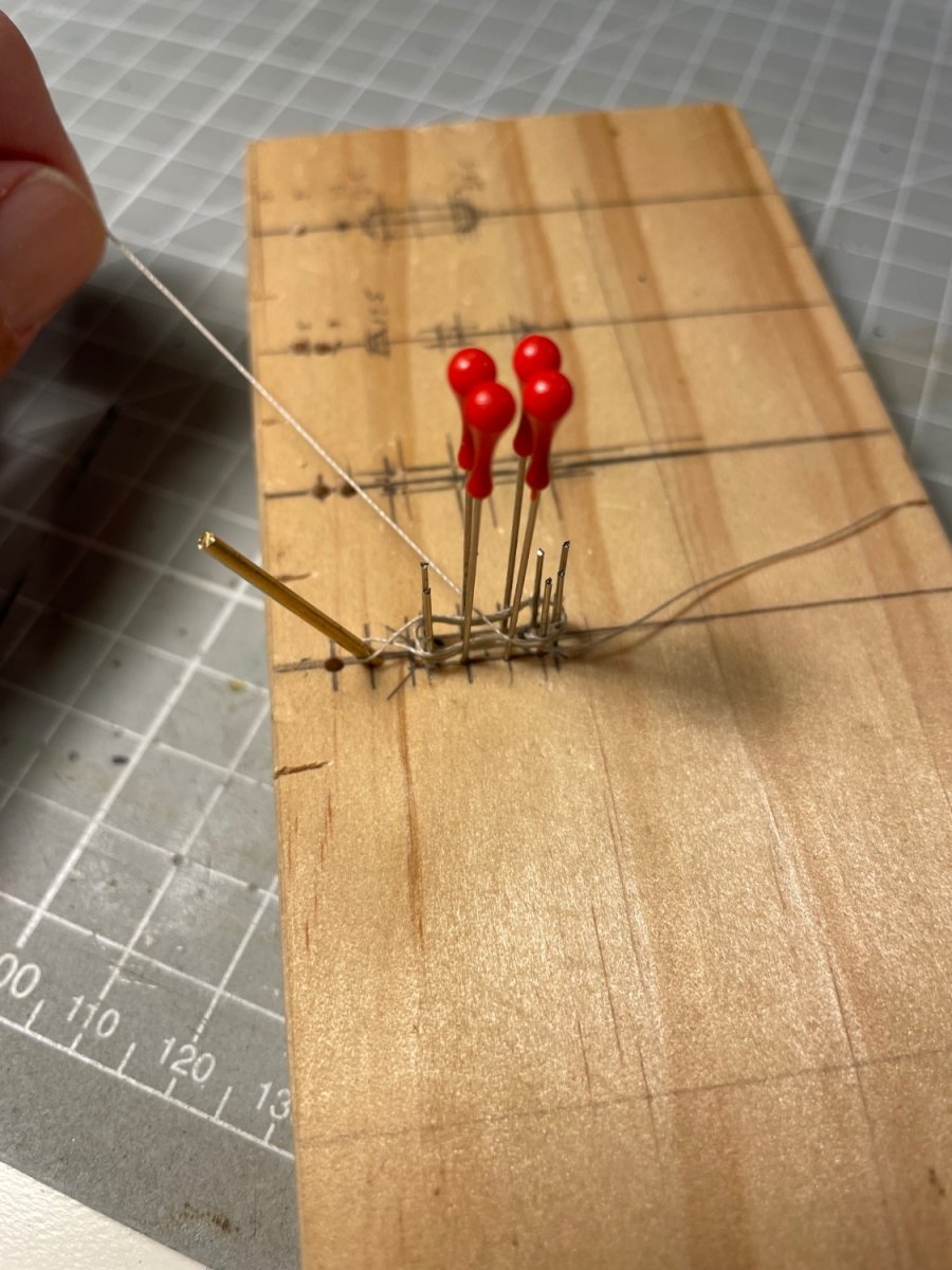
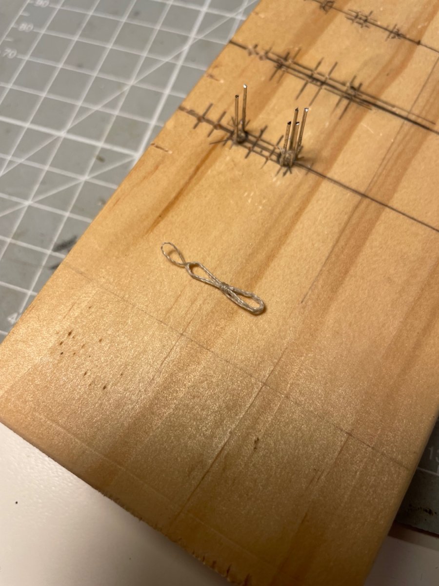
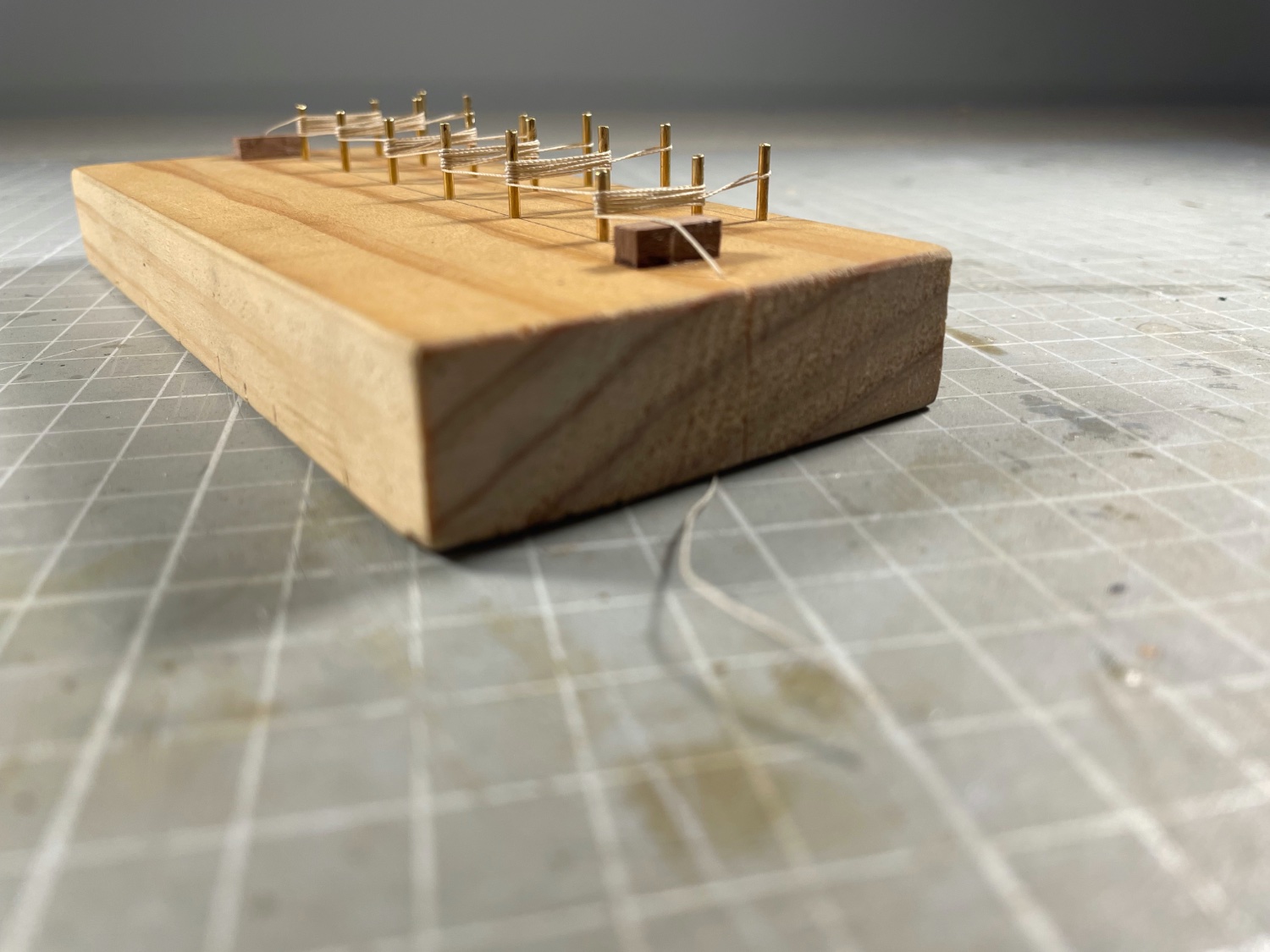
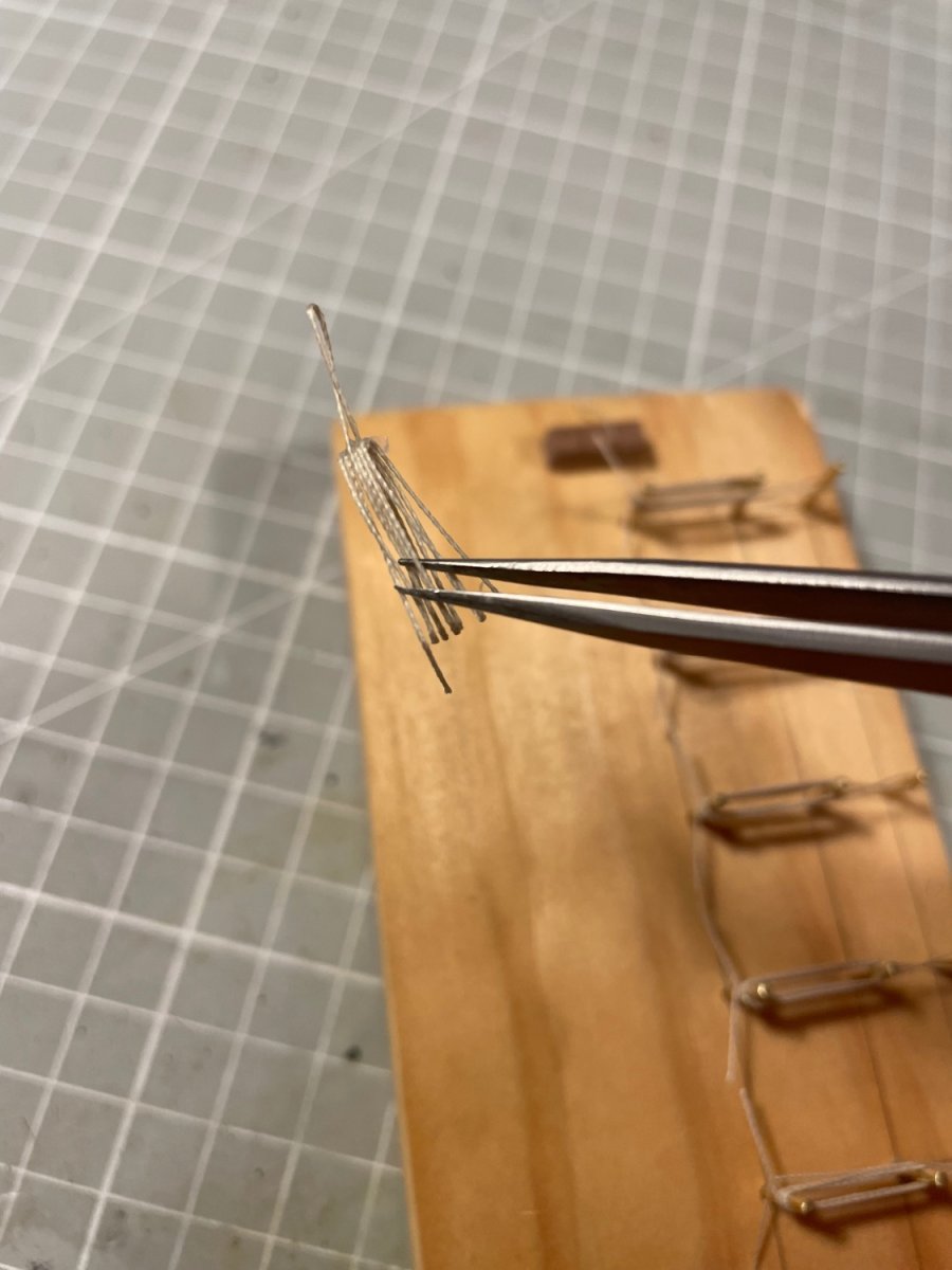
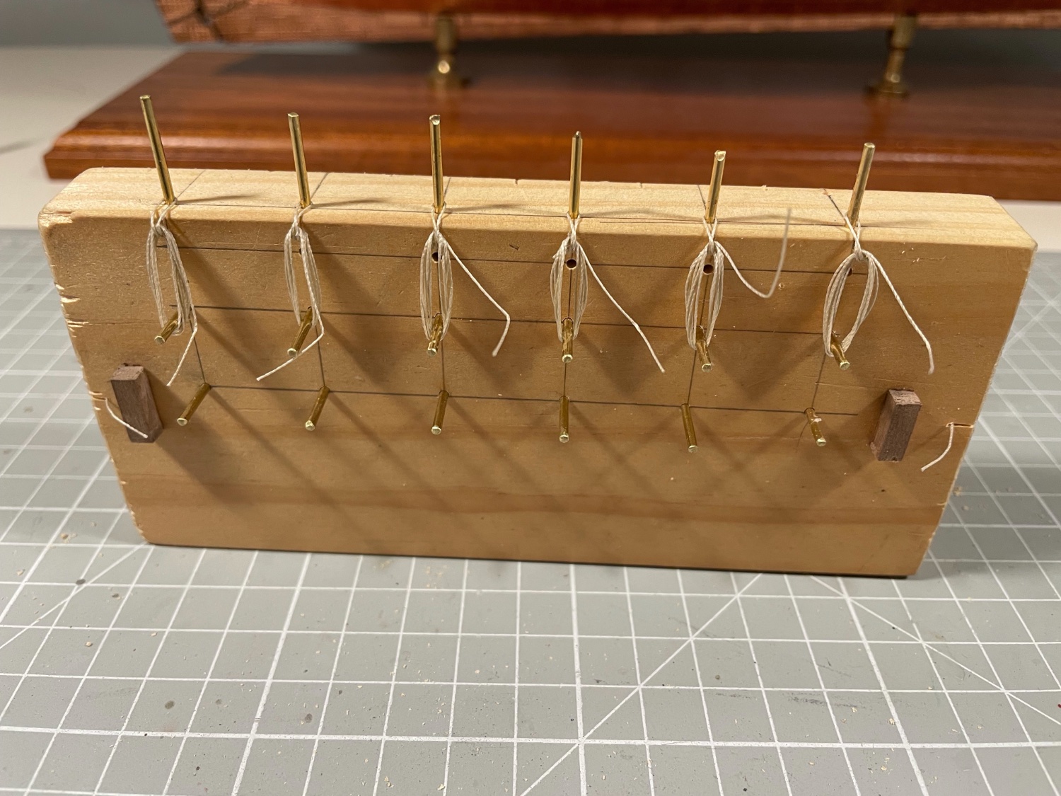
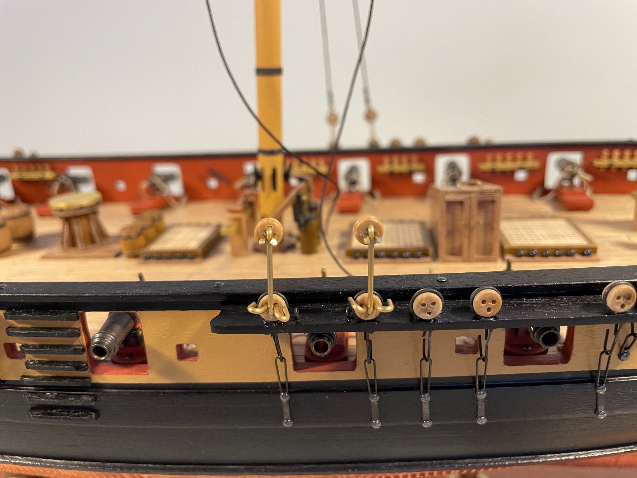
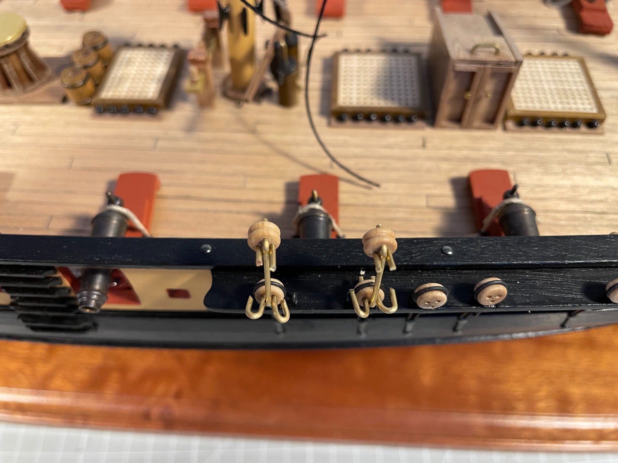
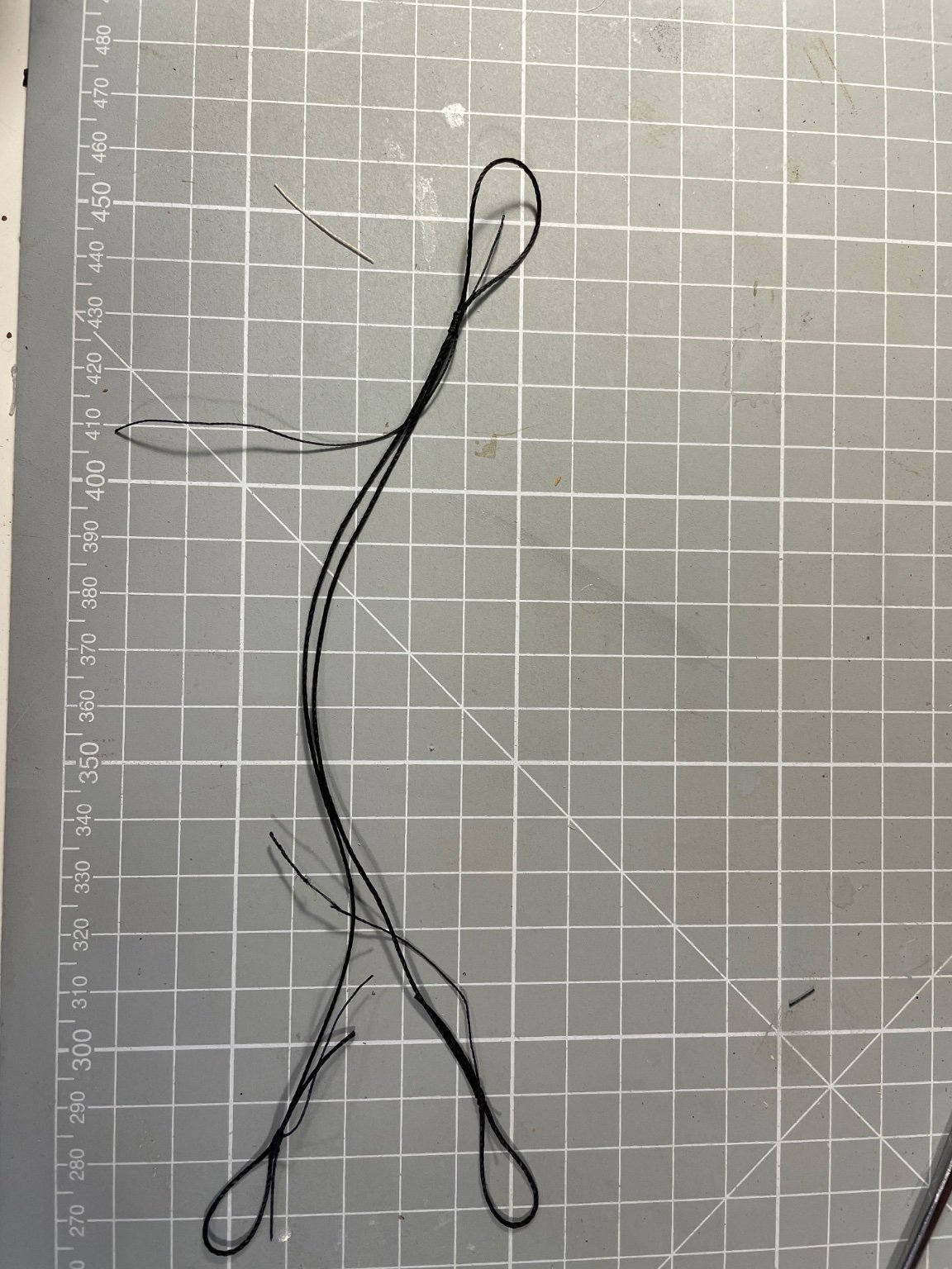
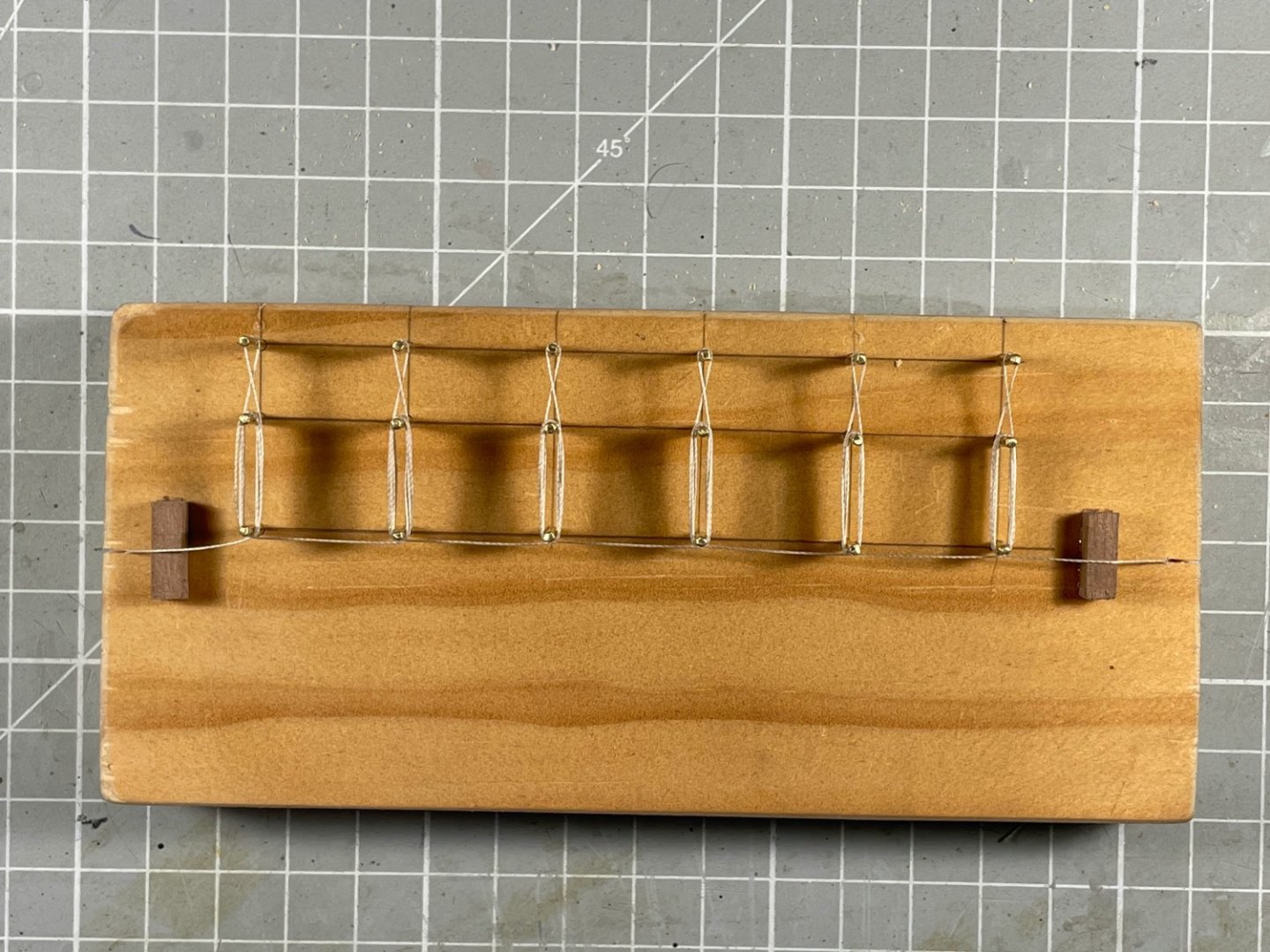
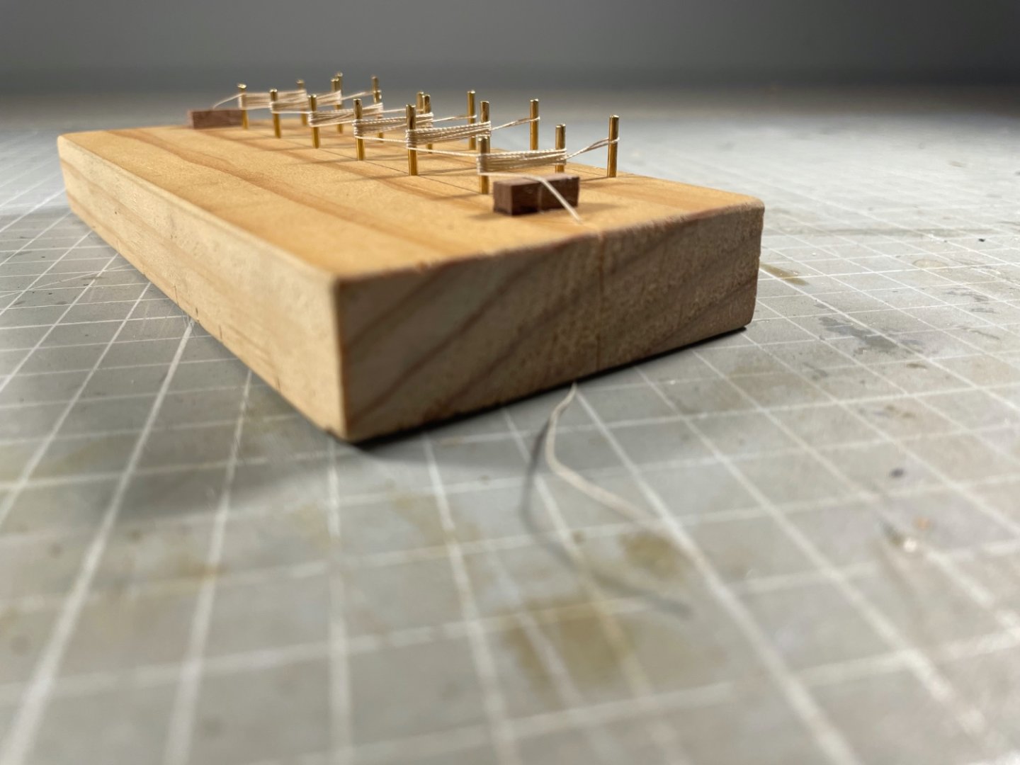
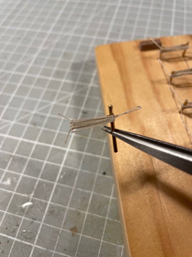
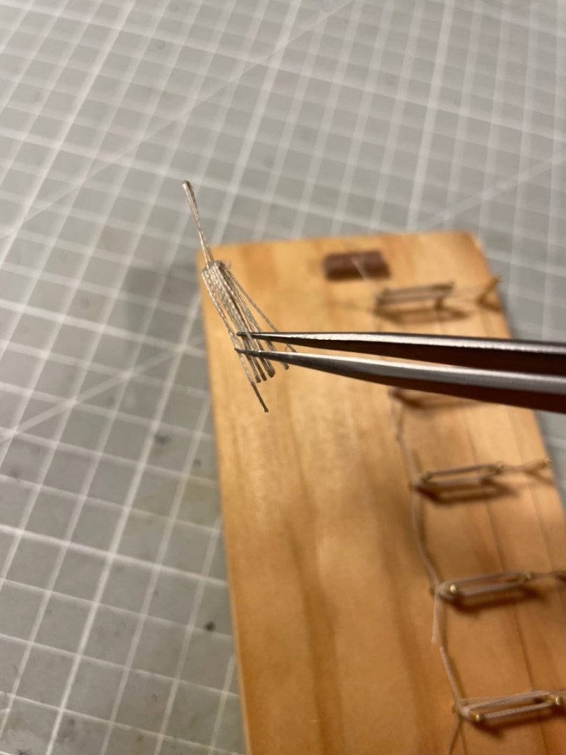
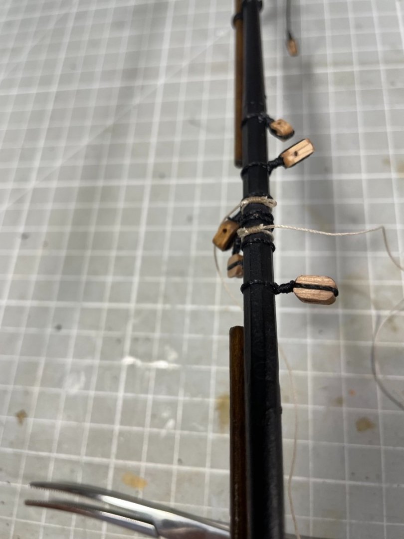
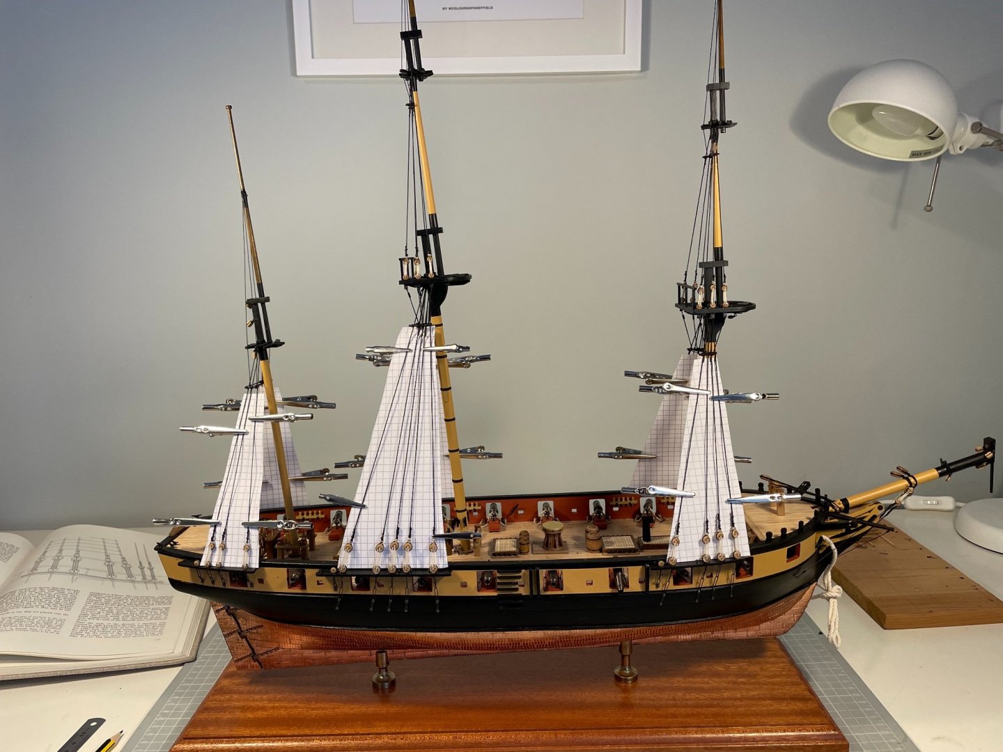
Rope Hanks I guess everyone starting on model boat building eventually confronts the making of high-class rope hanks to hang on their belaying pins. That is the stage I have reached. And most people who have a Jokita/Caldercraft kit finds that doing so, particularly for the 0.25 mm thread used for most of the running rigging, is not trivial. The problem is that the thread is not really made up as though it were a rope. I might-well have chosen to buy some higher quality thread, but I already had quite a few lines rigged, and in any-event, I have more-or-less decided to build the kit as supplied. So here's my journey of discovery The points of departure were: @Beef Wellington's Snake, which hangs the whole hank on the pin. This seemed quite common some years ago, but @BenD in his role as Rope Police, points out that's not really right. You can see what really good thread looks like, but that's not going to help me! He also links to a video of a method developed by Tom Laurier - see 3, below. My first real attempt was to use a method developed by @Peta_V. I had two problems - first I couldn't have pin 2 close enough to the top of the wooden block, so the coils hang too low on the belaying pins, and second, my scrawny thread did not drape at all well. I also found that the loop pulled-out to hang on the belaying pins inevitably sat-off to one side, and finally my thread loves CA glue - so much that a tiny spot of quite-thick glue wicks all over the place and stains the hank. I switched to PVA both for this technique and later, but ultimately I wasn't't happy that I could make decent hanks this way. Next up was Tom Laurier's technique mentioned in 1, above. I gave this quite a few attempts, but as I will explain later, with skinny thread the hanks look more like a rubber band than a proper hank. But, with the addition of a more-or-less historical binding around the middle, or waist, of the hank, thought this would be the way forward. Finally I came across a method on YouTube by PeterBurton50, that he developed for his HMS Diana (a Caldercraft heavy frigate) that not surprsingly works with their thread. Here's some glimpses of that journey. The figure below is the development of a jig - that can now be found on the reverse side. The first iteration is on the RHS with successive iterations moving to the left. The first 4 are Tom Laurier's technique from 4, above. You can see the holes for the pins, and note in particular the pair of holes/pins at the top (see his video to understand why). With the addition of a clove hitch around the waist of the hank (iterations 2,3 and 4 above) things were better. Although these were neat, and very reproducible, when installed on the model, they looked far too neat and far too reproducible. Iteration 5 is a hybrid of Laurier's method (with half-hitch) and Peta_V's, but still not right. At this point I stumbled across PeterBurton's method, trialled in iteration 6. Here's the production jig in plan view loaded with six hanks-in-making. I use 1.5 mm brass rod so don't need WD40, and have also found I don't need the plastic sheet. In part because I keep the hanks elevated (hence the little walnut blocks. As per the Method, a little bit of dilute PVA is added at the top of the hank-proper, which I dry in 1 min using a hairdryer, to give. The Method then has one of the loose ends trimmed (the one nearest the belaying pin) and the loop pulled through and glued while threaded on a nail (see the video). I borrow from Peta_V and use a second row of pins on the jig instead of the nail. The results are pleasing to my eye!


- 109 replies
-
- 6
-
-

-
- snake
- caldercraft
- (and 1 more)
-
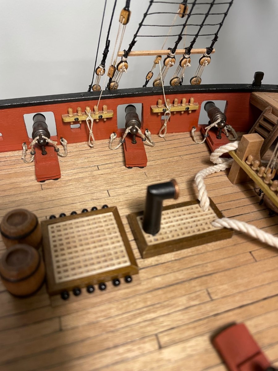
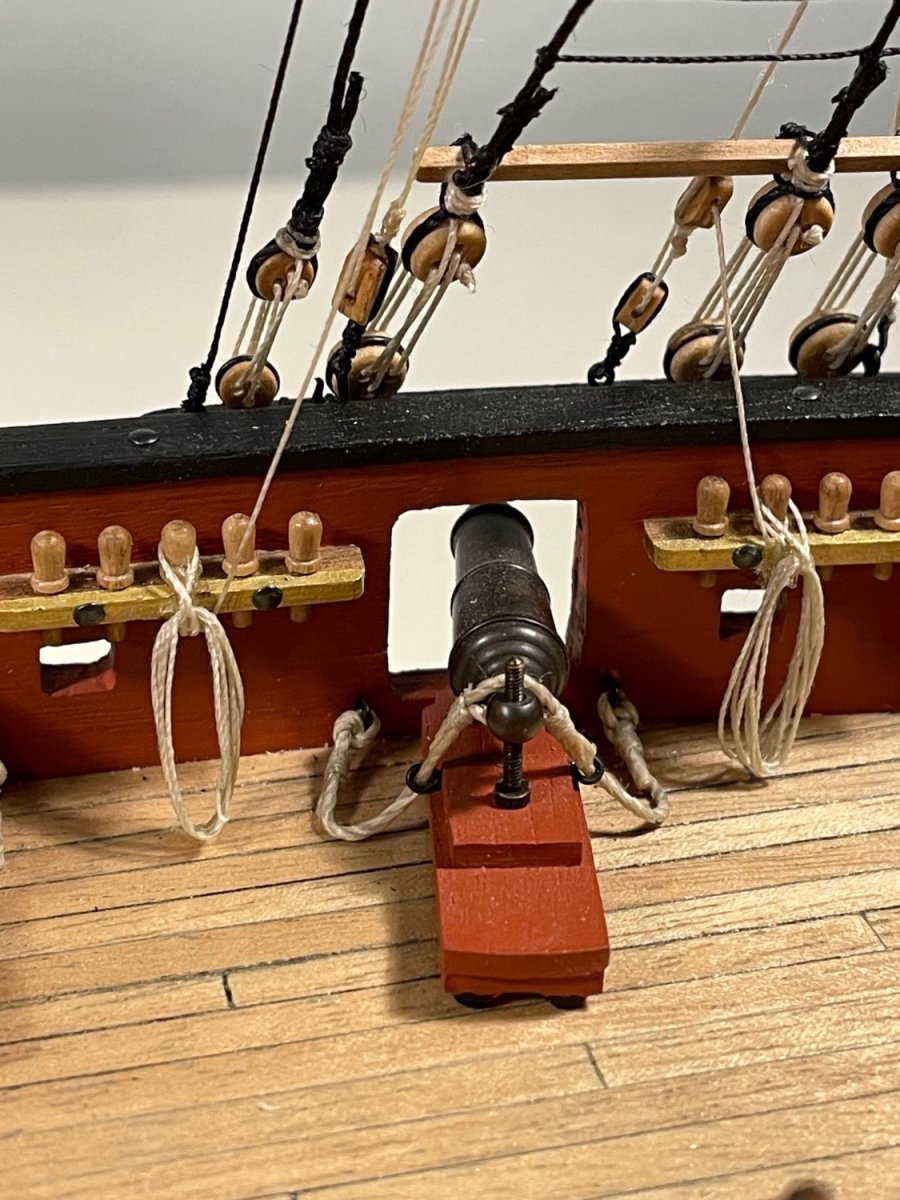
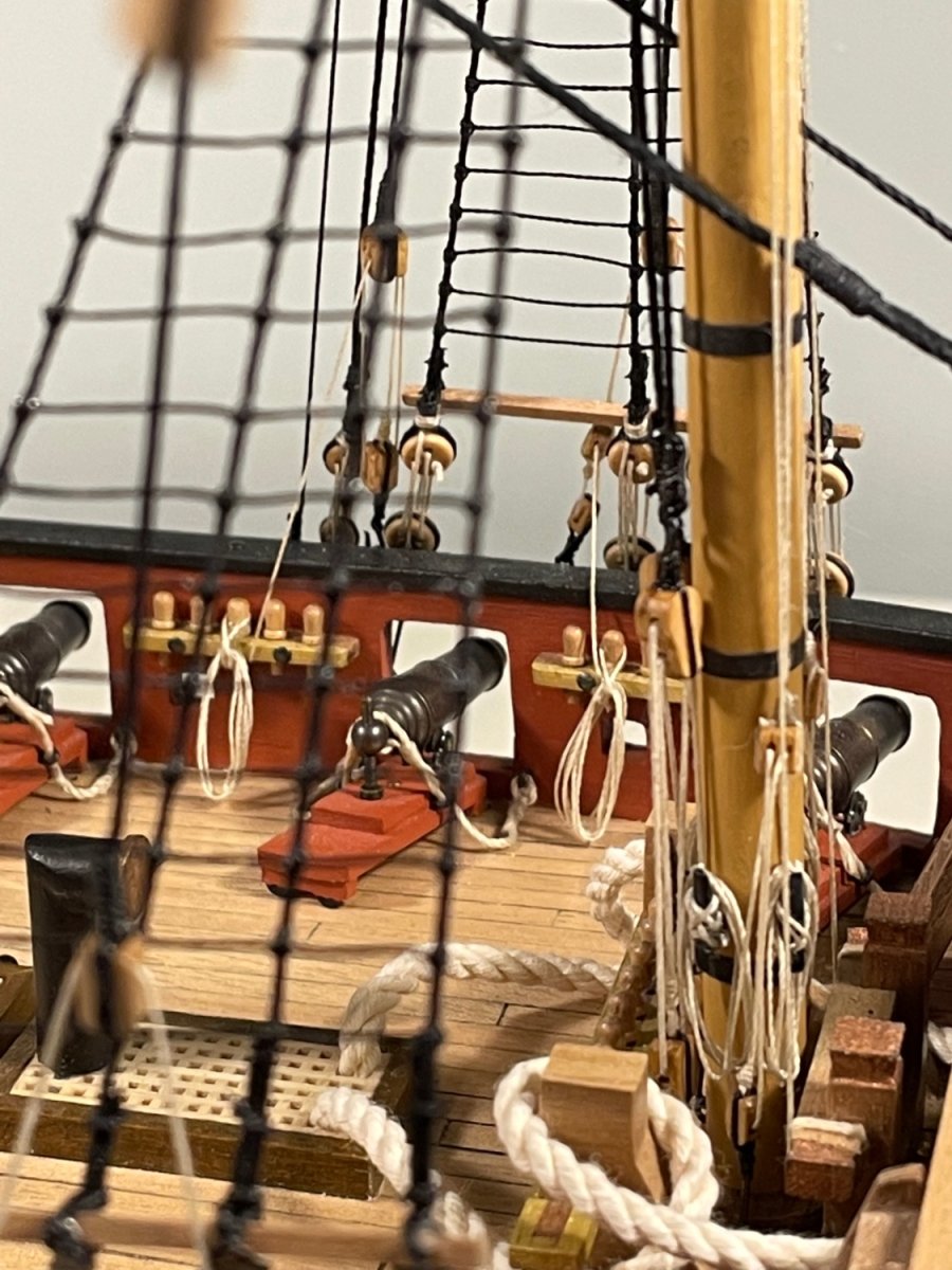
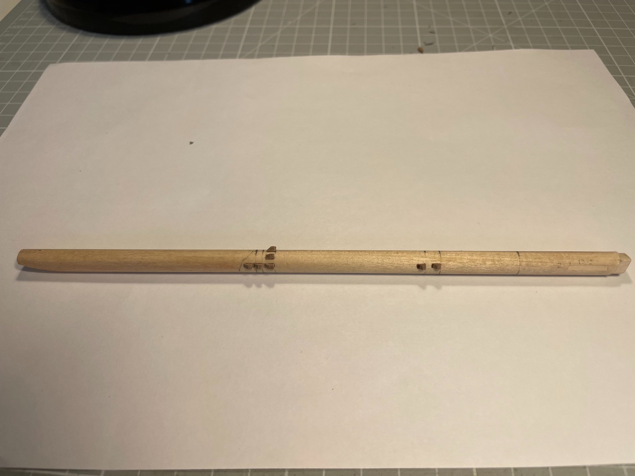
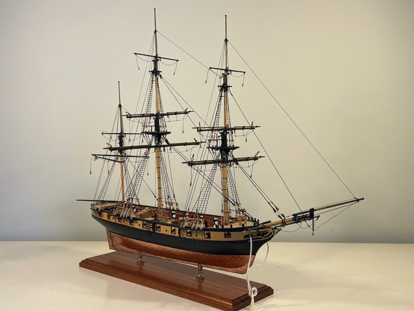
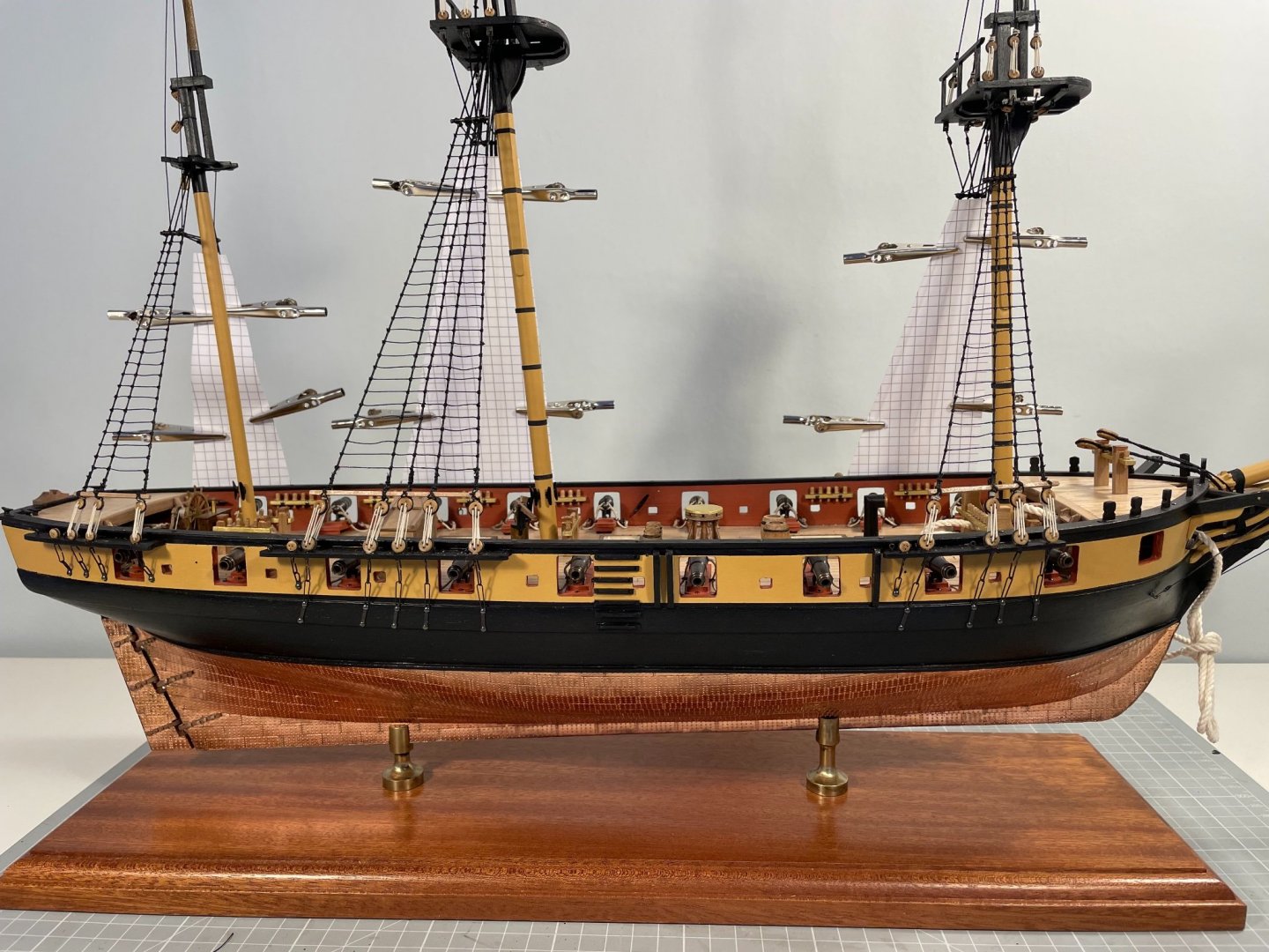
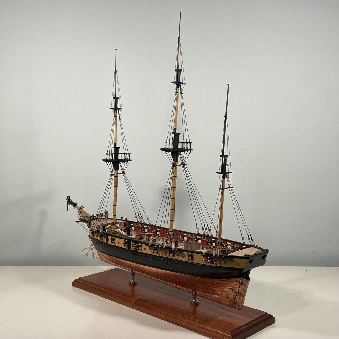
That's the standing rigging done. Took quite some effort - in part because there are more backstays than I thought, but to an extent because of kit issues. There are no instructions on the rigging - actually, one paragraph - but the drawings are reasonably complete. But they miss out a great deal of detail over how to belay the backstays, and incorrectly label the double blocks as singles. Turns out I was missing a significant number of blocks and small deadeyes. Caldercraft were very helpful in shipping me what I needed - at no charge. So marks off for instructions, but bonus marks for customer service. Anyway, to the results. I had a go at making rigging mice from thread, but had no success at all. Decided to makes them from dowel, turned down to an appropriate size and shape and then painted. I don't think I got it quite right, but it the results was far better than anything else I produced, and from any kind of distance look fine. In the pics below you can see that there are now a few belayed lines, so the next, indeed current, project is making hanks to put on the pins and cleats.


- 109 replies
-
- 8
-
-

-
- snake
- caldercraft
- (and 1 more)
-
Your patience continues to astound. Beautifully done.
-
We are in sync. Shorter days and cooler air means get back to the shipyard.
-
So, 7 months later I'm back - 3 months downunder, a month cycling and then a kitchen to build. Re-engaged with some anchors and some stays.
- 109 replies
-
- 8
-
-
- snake
- caldercraft
- (and 1 more)
-
Thanks Andrew - no ship building. Traveling, cycling and some sun. I’ll be back ship building soon enough - absence makes the heart grow fonder.
- 109 replies
-
- 1
-
-
- snake
- caldercraft
- (and 1 more)
-
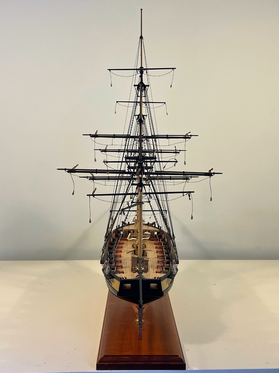
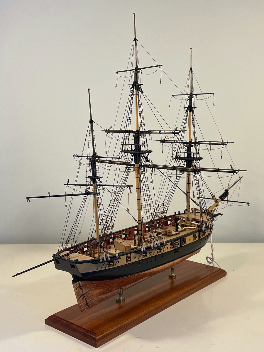
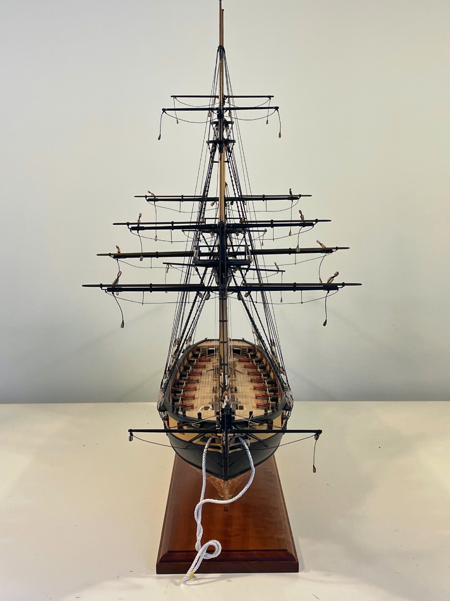
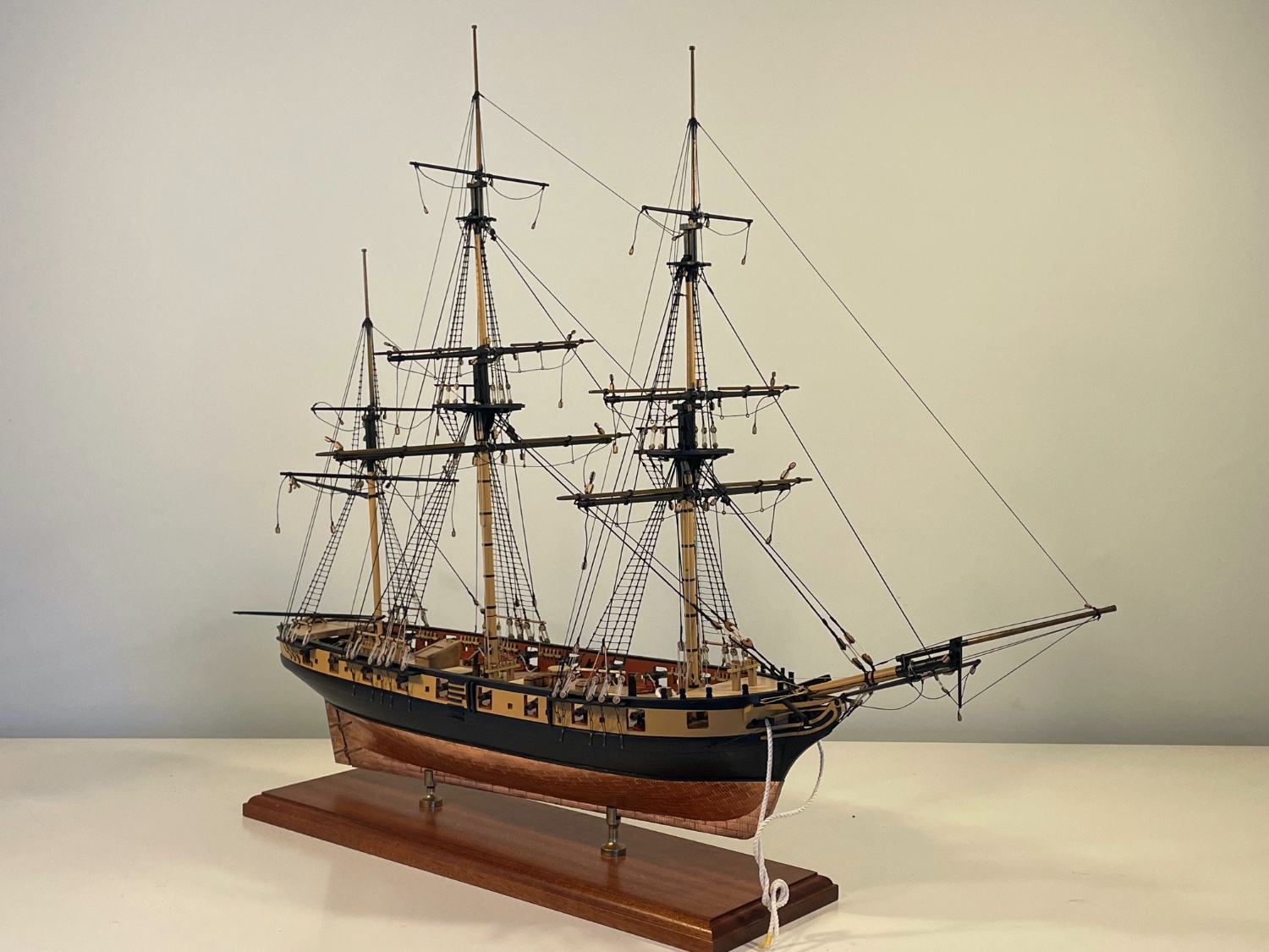
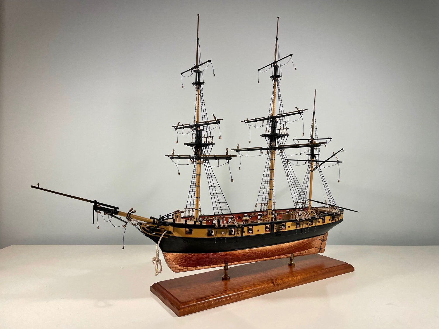
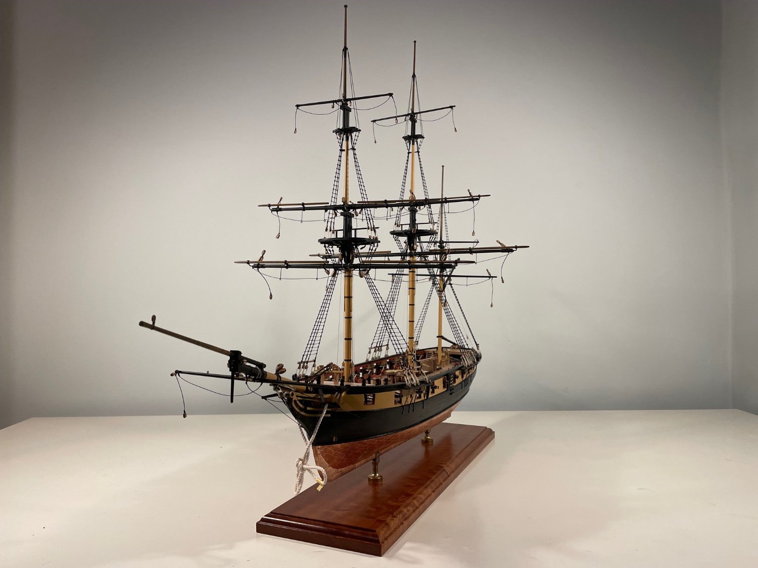
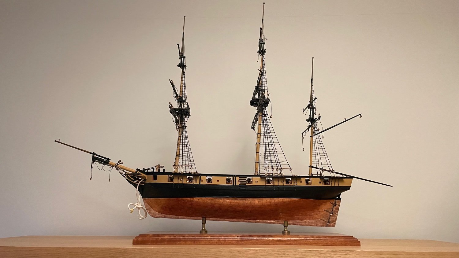
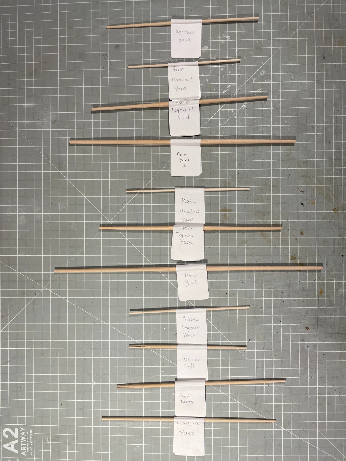
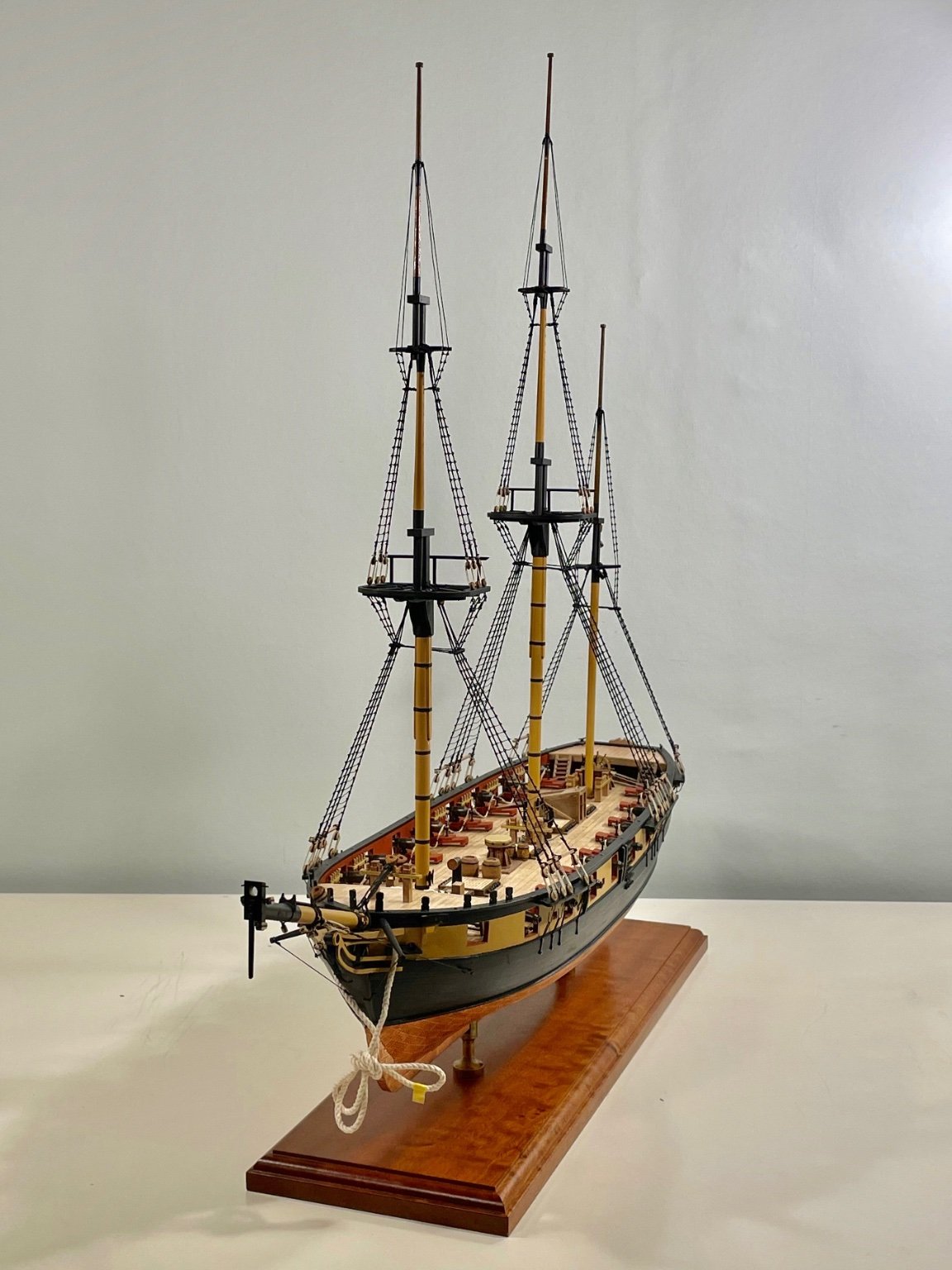
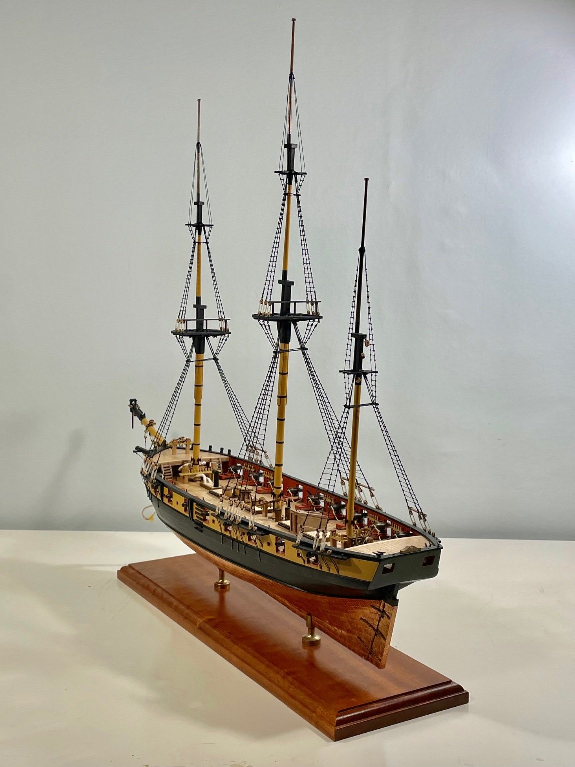
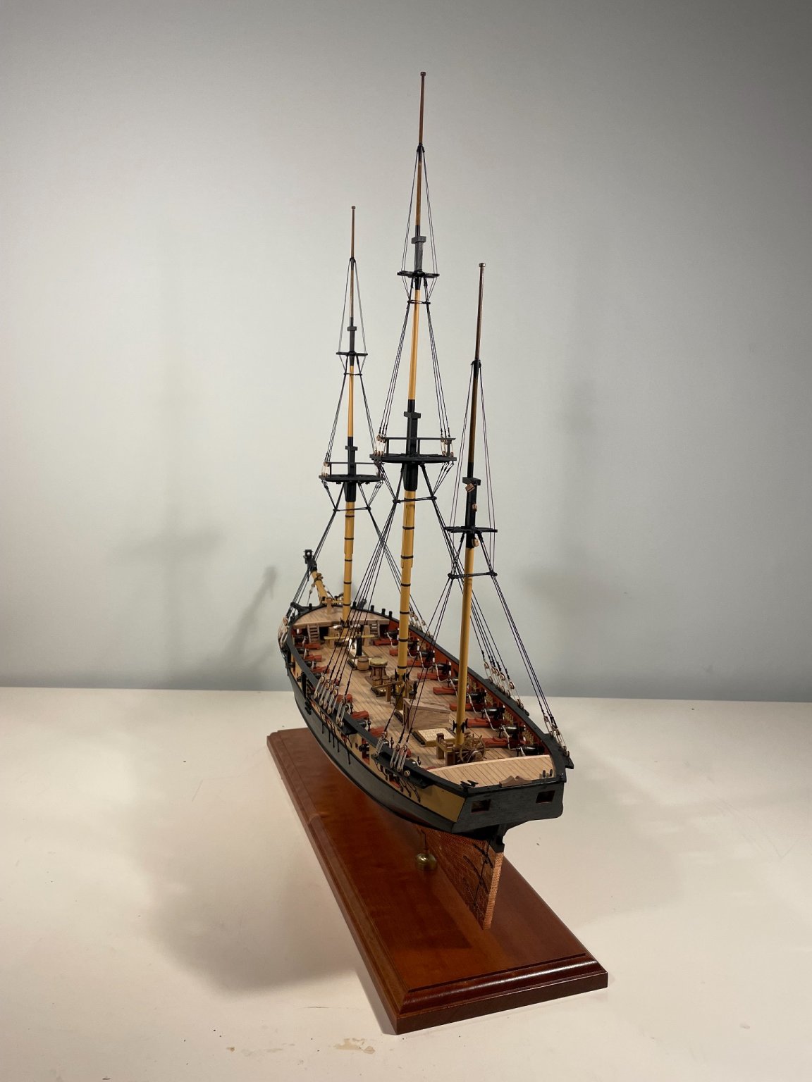
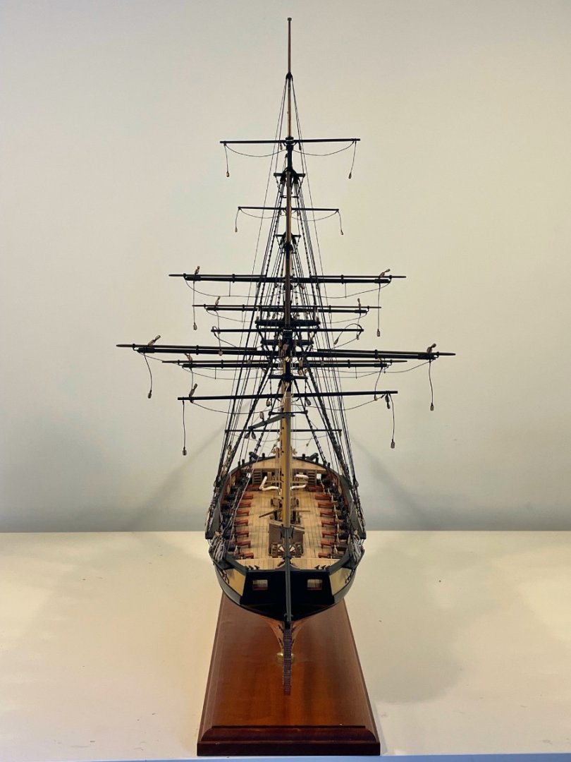
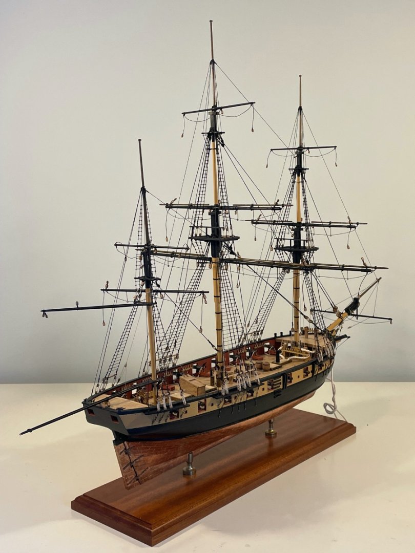
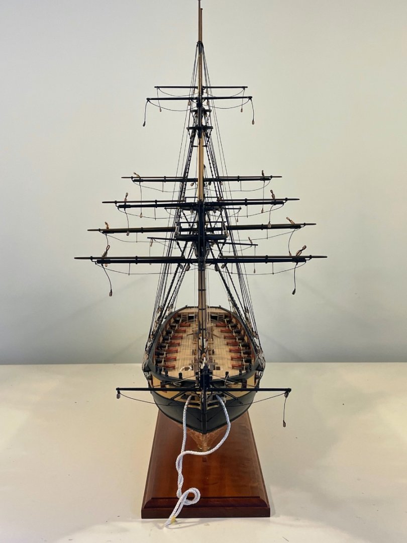
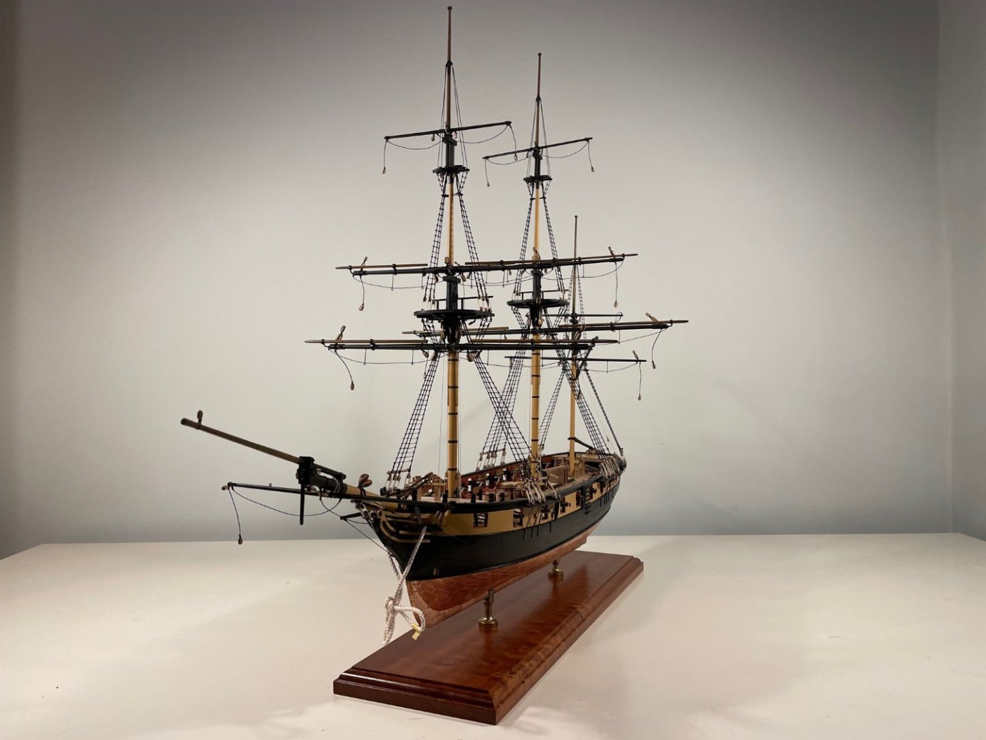
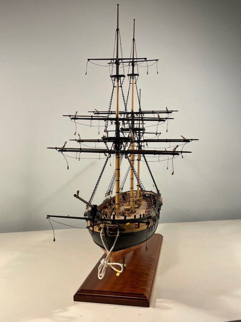
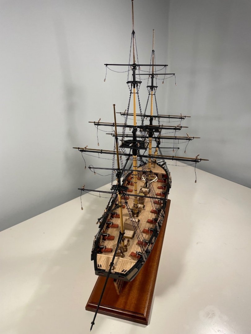
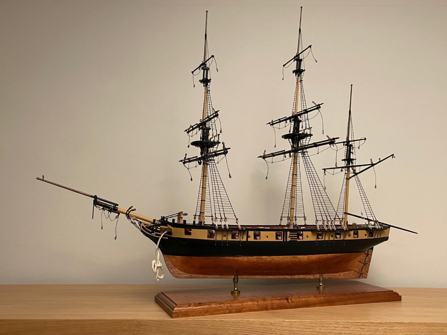
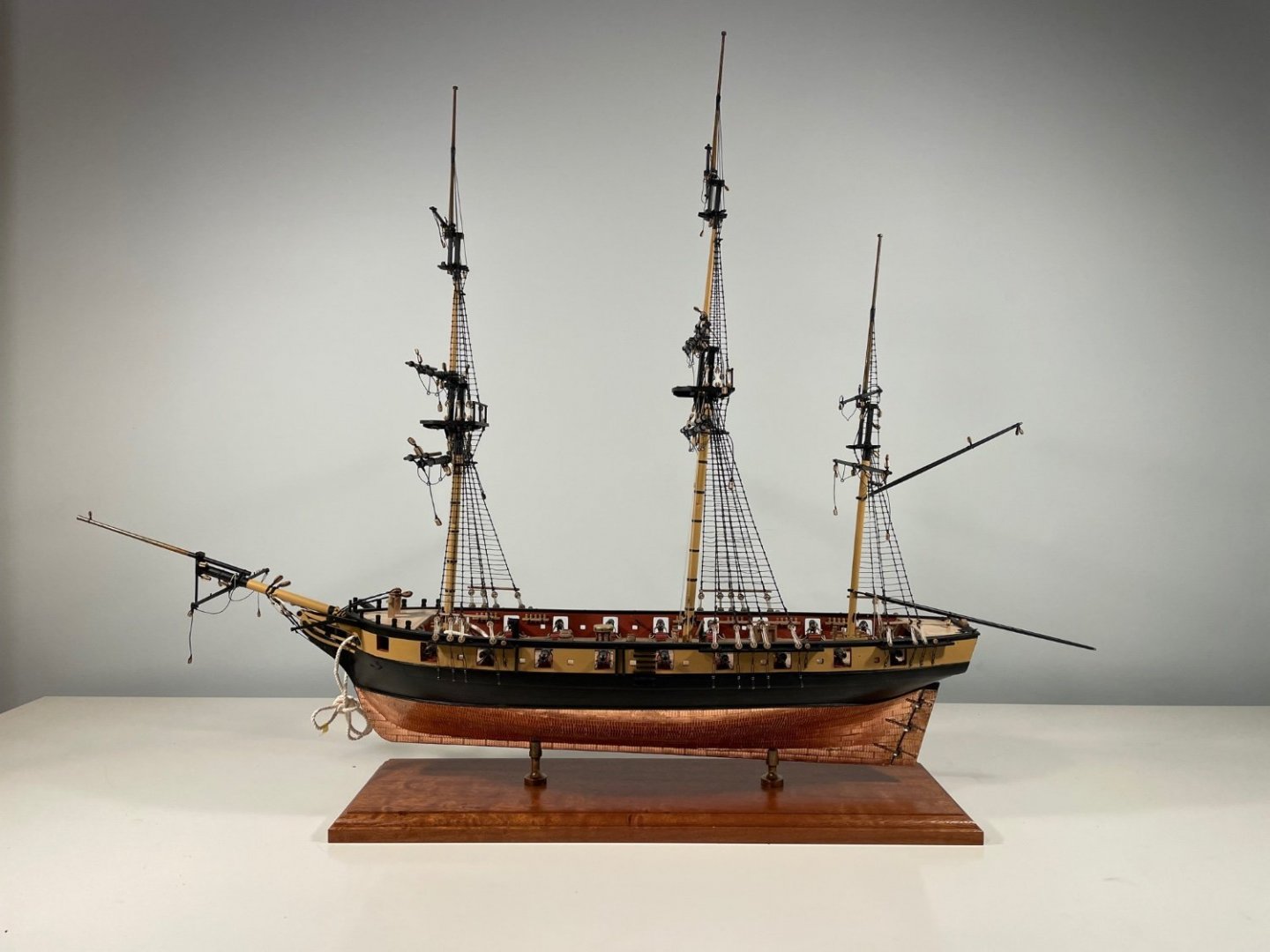
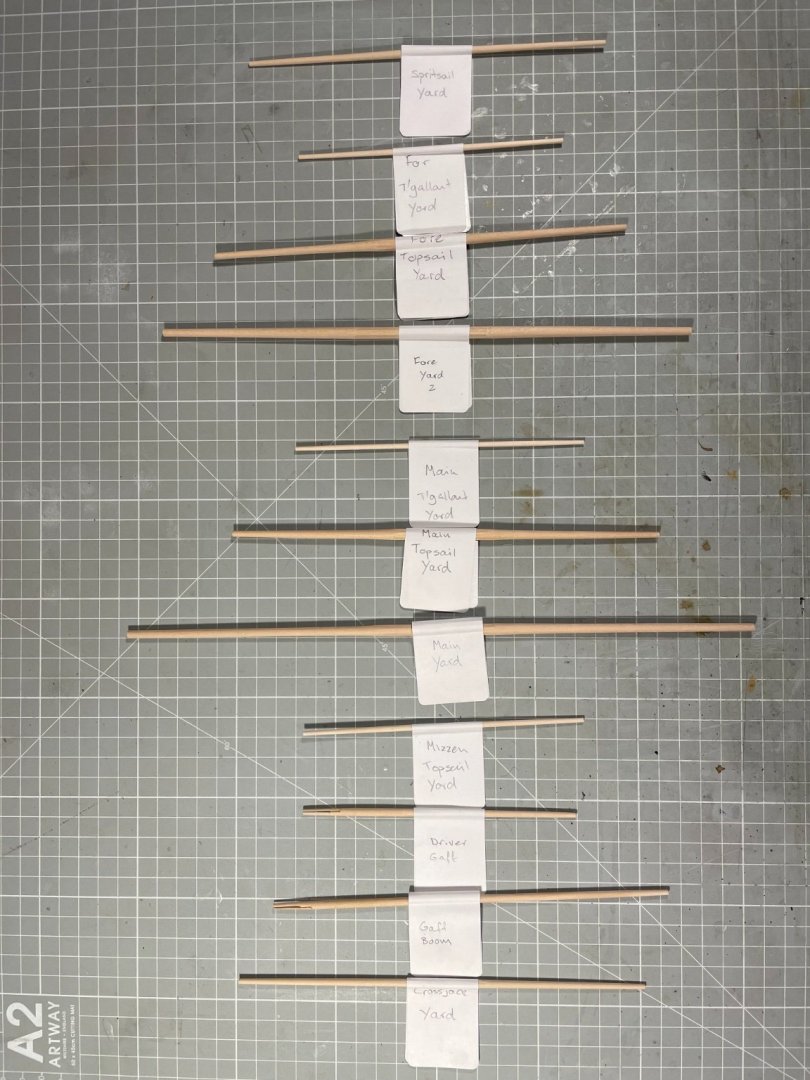
And so, a full set of spars! Looking now at what this constitutes I can see why it was such a lot of work. I will admit to getting frustrated at times - mainly because I made the same errors over and over - most often getting the sequencing wrong, and when tying the yard to the mast, managing to trap foot-ropes on running rigging. Less haste, more speed, as the saying goes. Though never said by me! Here is a slew of photographs to mark this important event, and the fact that I'm gong to take break for a few months to do some other things.


- 109 replies
-
- 5
-
-
- snake
- caldercraft
- (and 1 more)
-
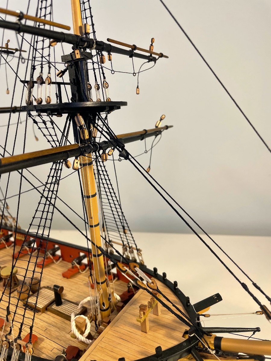
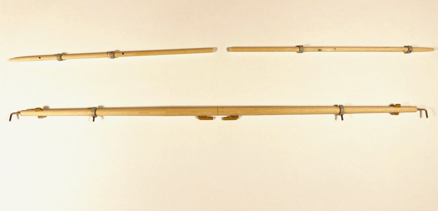
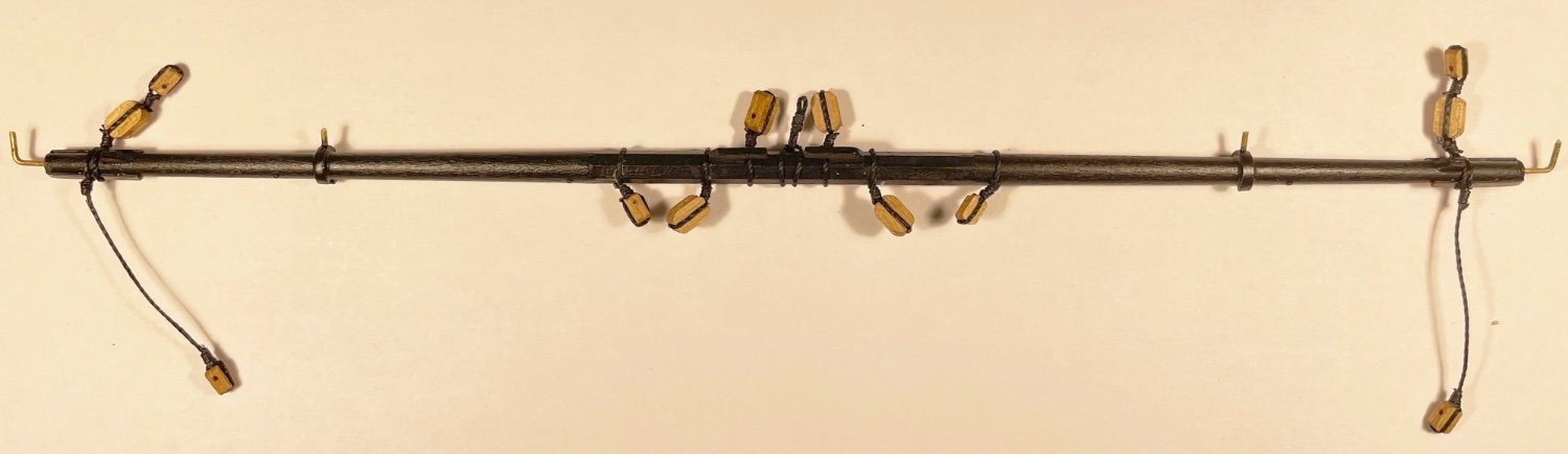
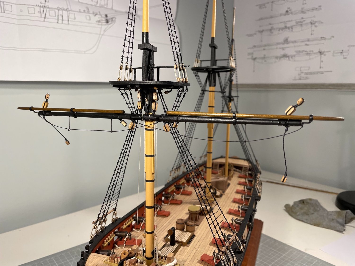
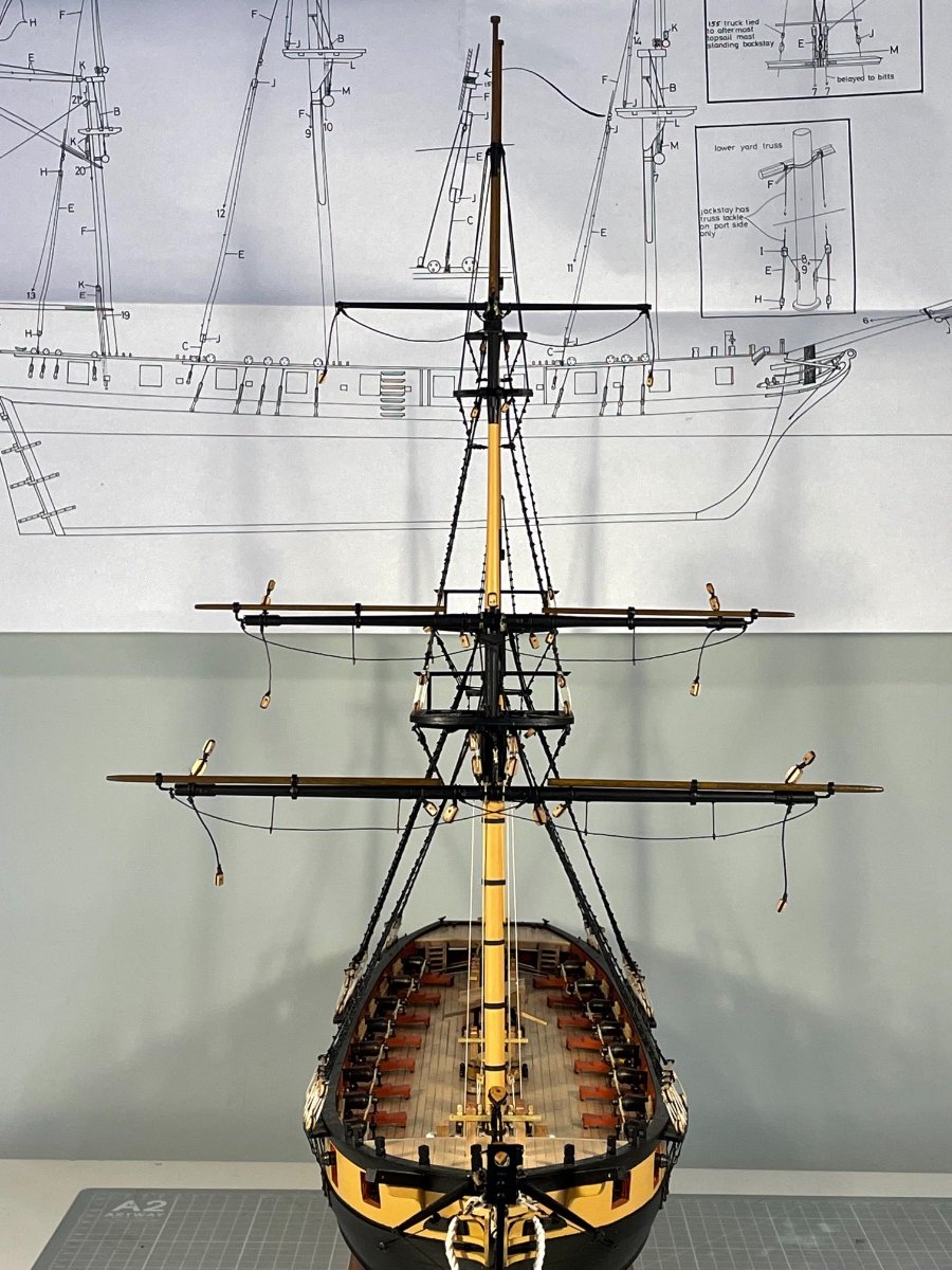
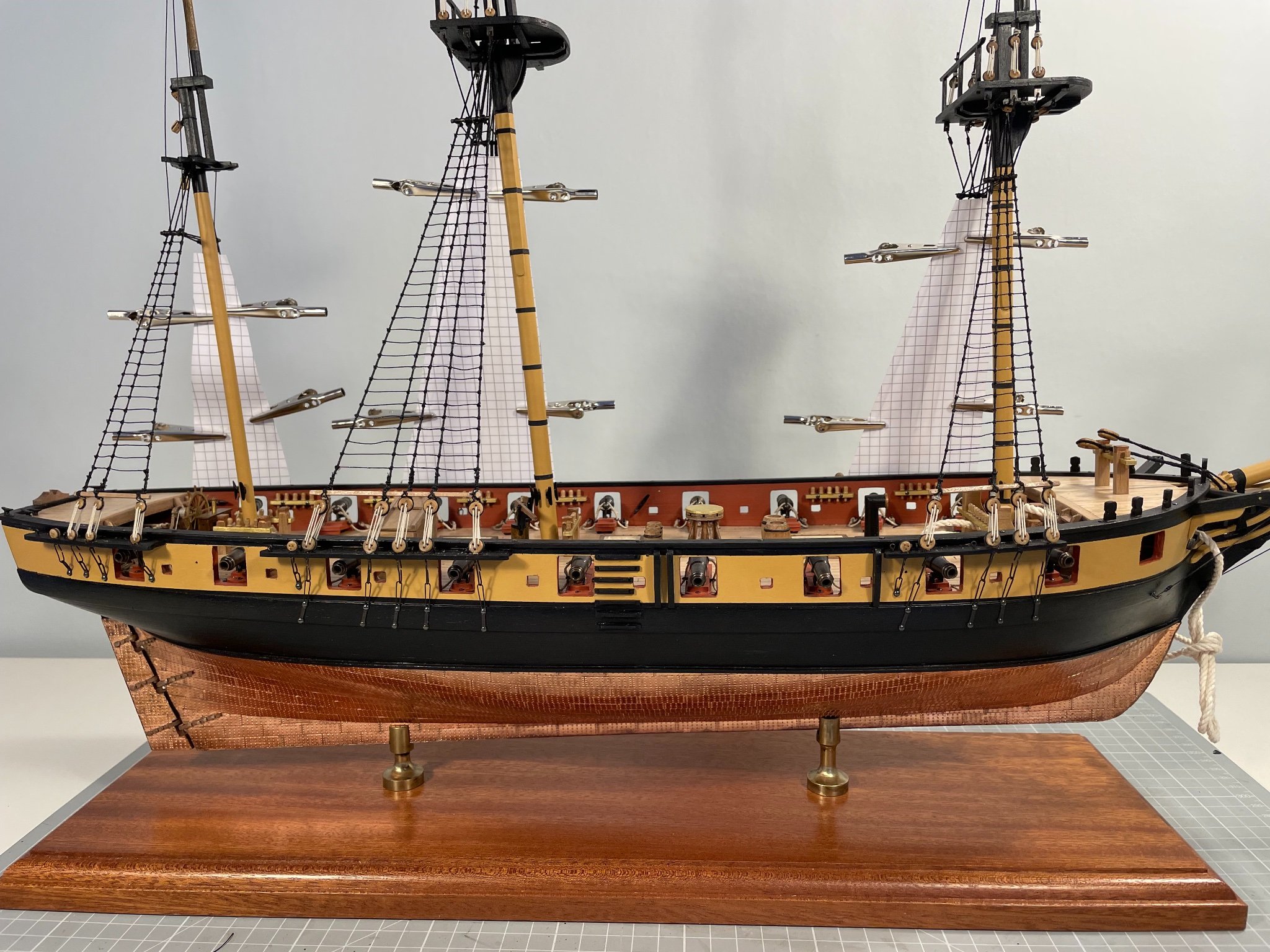
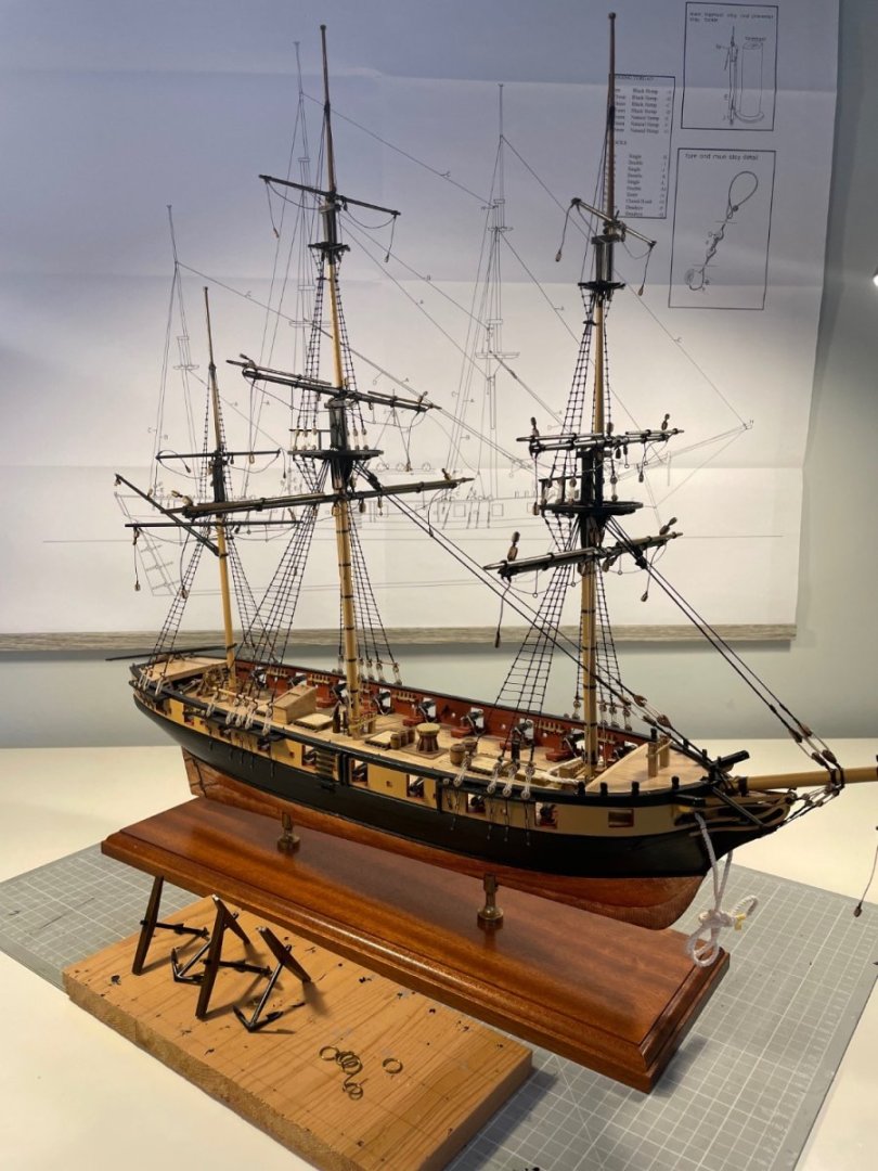
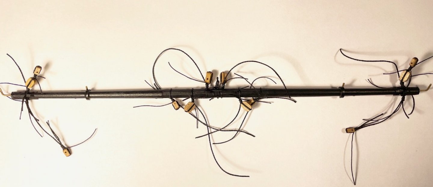
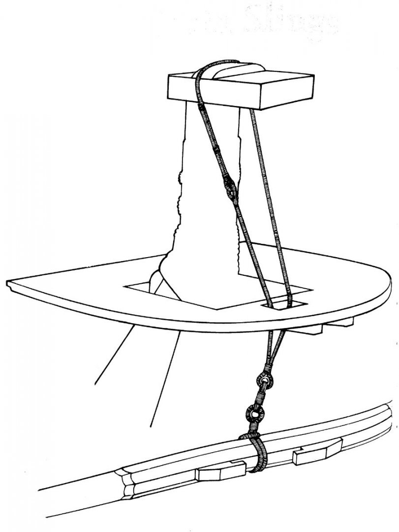
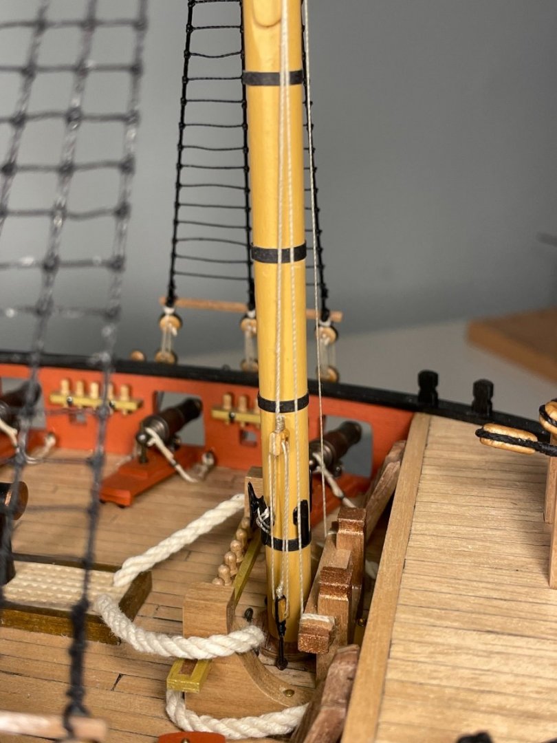
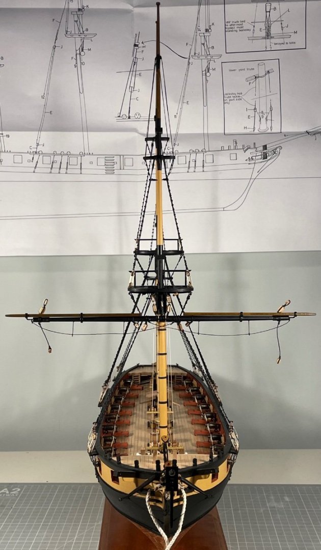
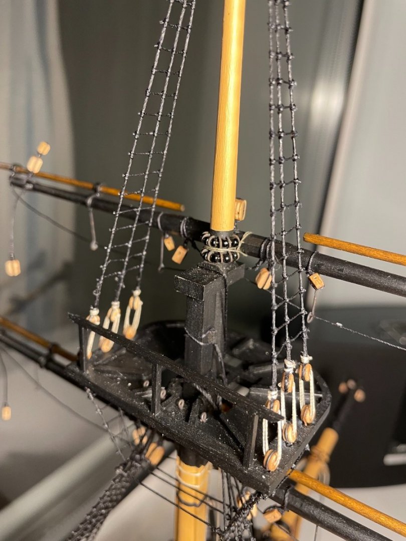
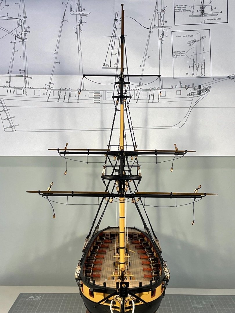
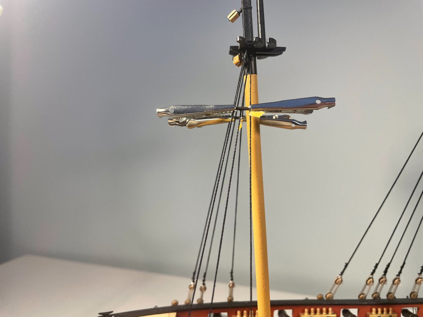
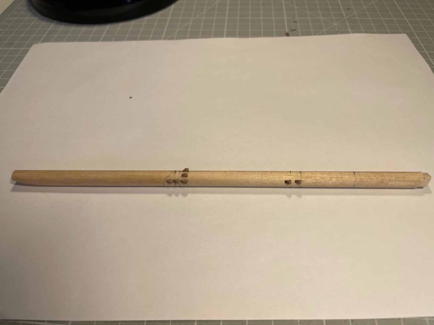
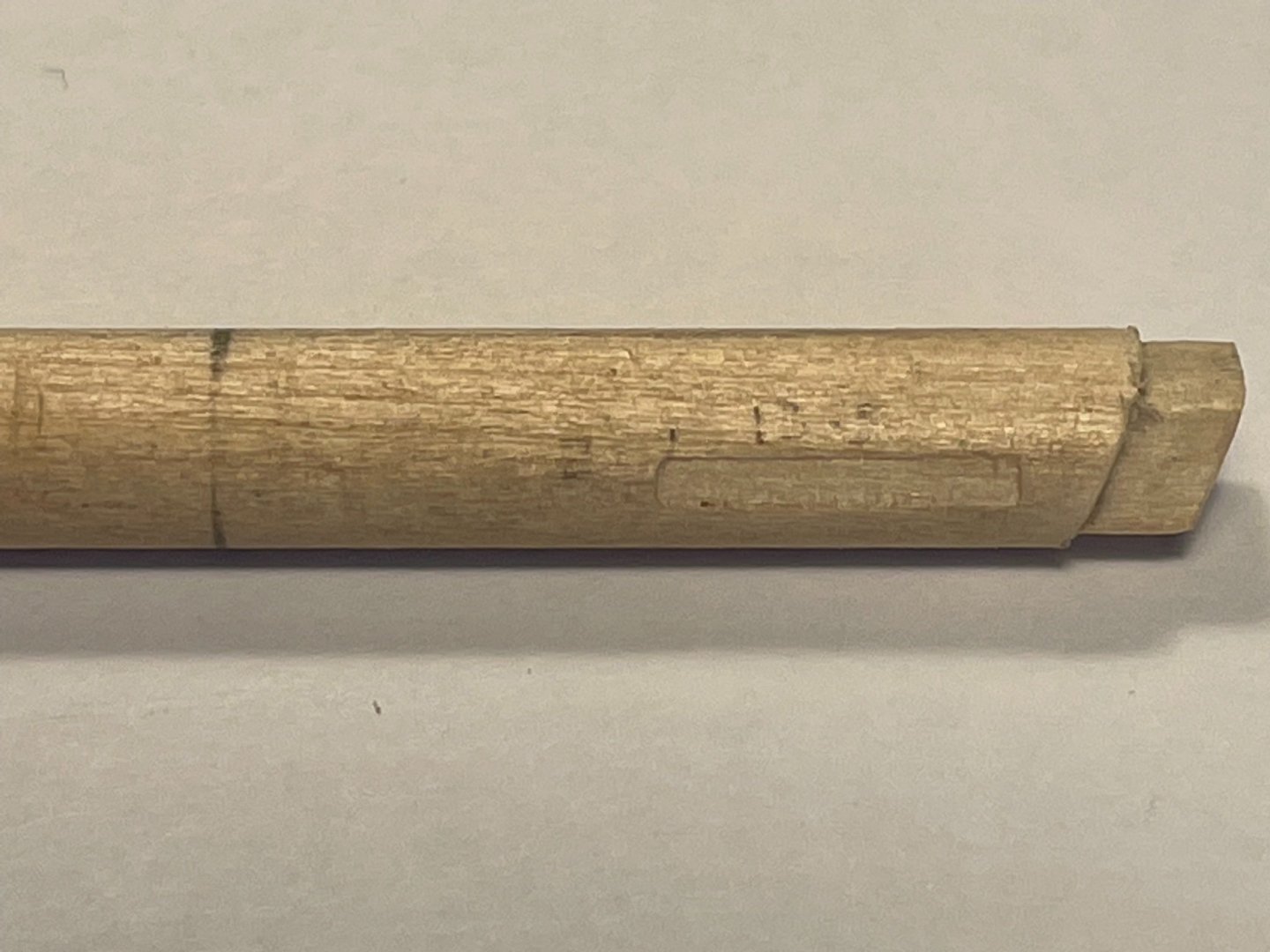
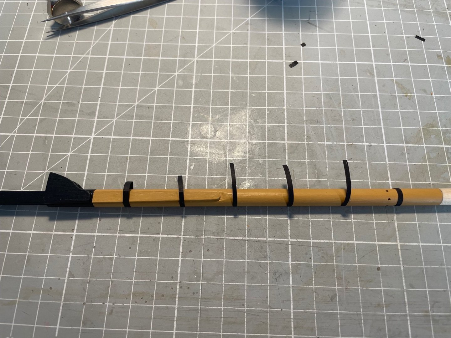
The Shipyard opened a couple of weeks ago, and since then has been rigging yards. Slow going, indeed very slow going, at first, but as is so often the case it gets easier with experience. The Caldercraft instructions are hysterically bad. They don't quite say: "now rig the ship", but they might as well. The drawings are quite good, though not meticulously accurate. What really annoys me is that quite a bit of work would be much easier to do before the masts were made up - as I will show. I have only completed the formast yards, and started by gluing on cleats and drilling holes for the various fittings. The following rather poor images show the topsail yard from above with 1 mm holes to mount the stunsail booms, from below with 0.7 mm holes for the stirrups and then with the stunsail fittings attached. I chose to have the 1 mm rod penetrate both yard and boom via the two mountings. This way positioning of the booms was much more reliable than just sticking them in the mountings. It took me quite some time to realise that the booms don't sit directly above the yards, but rather at 45º projecting up and forward. Accurately machined octagonal section on the yards are a great help in setting all this out, since it is simple to clamp the yard at incrments rotated by 45º. Blocks fitted and yards painted. The booms were stained brown and varnished as will be seen later. I've shown the lashings (is that the word?) before and after they were trimmed to get across something of the scale of work In order to secure the jeer blocks and the sling some cleats are needed (and excluded from the instructions). Those on the square section of the lower mast, to support the jeer blocks, are fairly standard, that on the cap "reflects" what can be seen in a number of books - and certainly allowing the slings to rest on the topmast would have made removal of that mast impossible without removing the slings. Here the jeer blocks can be seen in place - and oh how I wish I had known to rig them before the mast was assembled The yard is pinned to the lower mast, but is meant to look as though it is held up by slings and jeers and attached to the mast by a rather elegant truss, shown here prior to rigging on the mast: And here we go, foryard crossed: You can see the stunsail booms - which I think look much more pleasing to the eye with some stain, rather than the naked timber often shown. Also visible are the horses and stirrups, which annoyingly I forgot to add before fixing the yard - my fault this time not that of the instructions (Details visible here but to be shown in a moment are the slings, truss and its pendants and the jeer lines - how these differ from falls or ties/tyes, I do not know.) Here is a close up of the slings - and is a reproduction of the arrangement shown in Petersson - which came off quite well, I think. I thought it best to complete the associated running rigging before the standing rigging gets in the way So here is the fully-rigged foreyard The other fore yards soon followed, and differ only in that the two upper yards have parrals not trusses, shown here on the topsail yard And finally, here is the full set of foremast yards Happy days! Now on with the other two masts armed with some experience.


- 109 replies
-
- 4
-
-
- snake
- caldercraft
- (and 1 more)
-
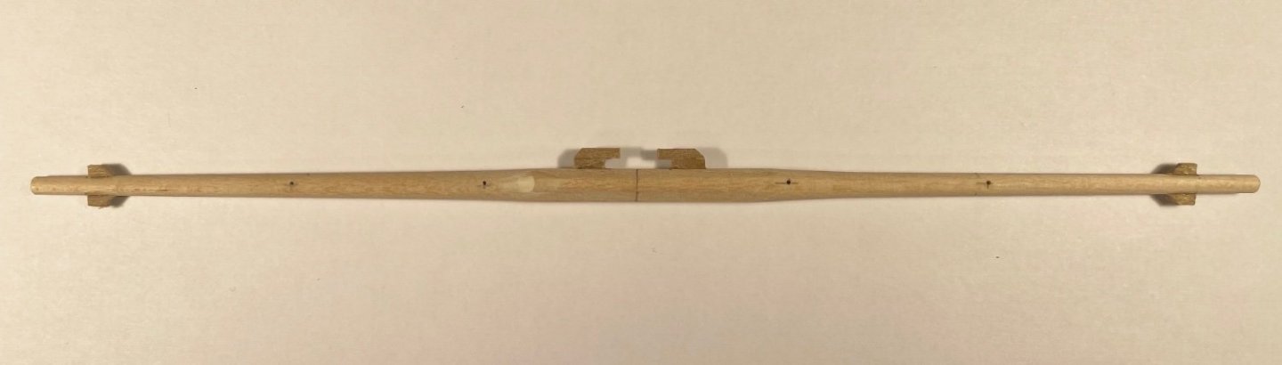
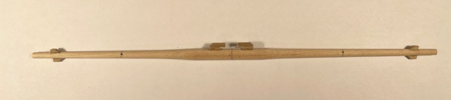
To follow up on @DaveBaxt's comment and address the next stage of the build, I've had the milling machine and lathe out again, to make the remaining spars. On the larger spars, the octagonal sections were milled using the dividing table and ever-more elaborate ways of supporting the workpiece, and the taper obtained on the lathe first with a gouge and then four grades of sandpaper. For the smaller spars, octagonal sections weren't called for and the taper was obtained just with sandpaper. The octagonal section require 0.25 or 0.15 mm or material removed for each face, so to get a regular shape the workpiece needs to be horizontal with a tolerance of about 0.025 mm in a 50 mm run, ie 0.03º. I've only just calculated that number and am astonished at the level of precision I was able to achieve on the Proxxon: 0.025 mm is 1 thou! The shipyard closes tomorrow in order to accommodate the Rear Admiral, and with the Full Board in residence, the shipyard matey will be keeping a low profile. So Merry Christmas and Happy New Year to all.
- 109 replies
-
- 4
-
-
- snake
- caldercraft
- (and 1 more)
-
Saw some pics and was very impressed with the neat, tidy finish. So I thought I would follow along. Mike
-
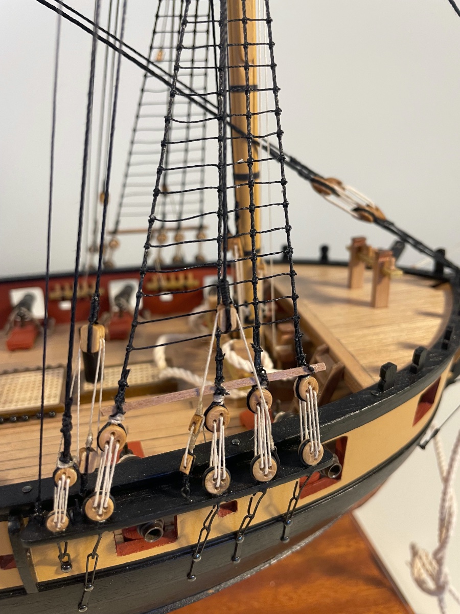
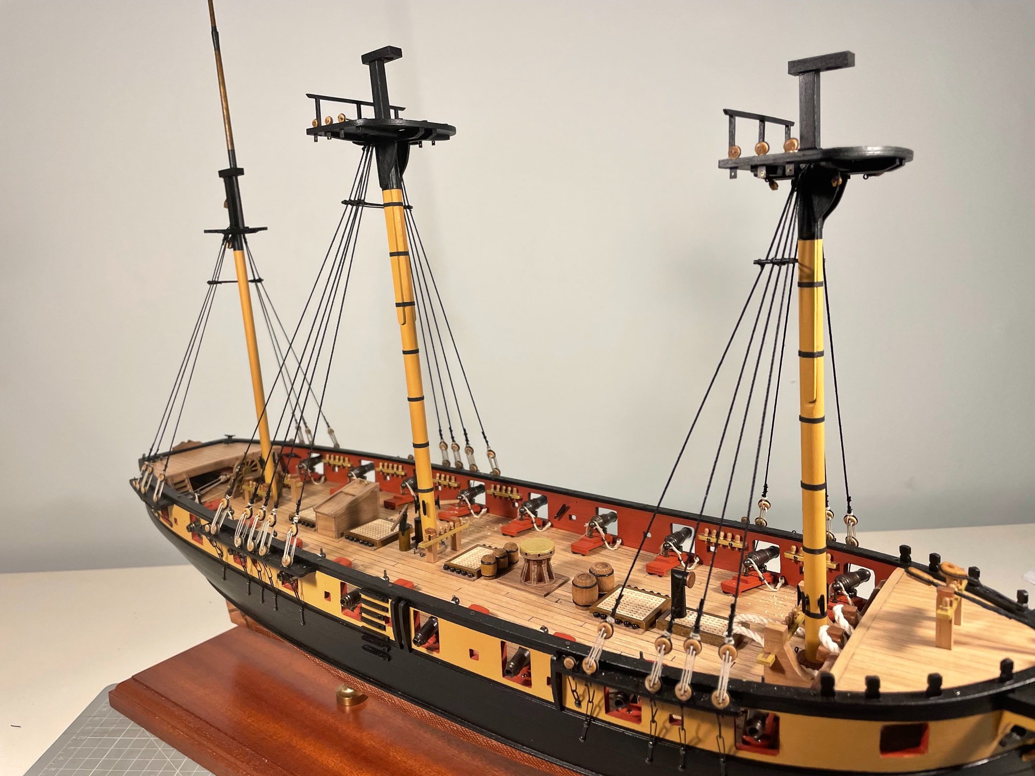
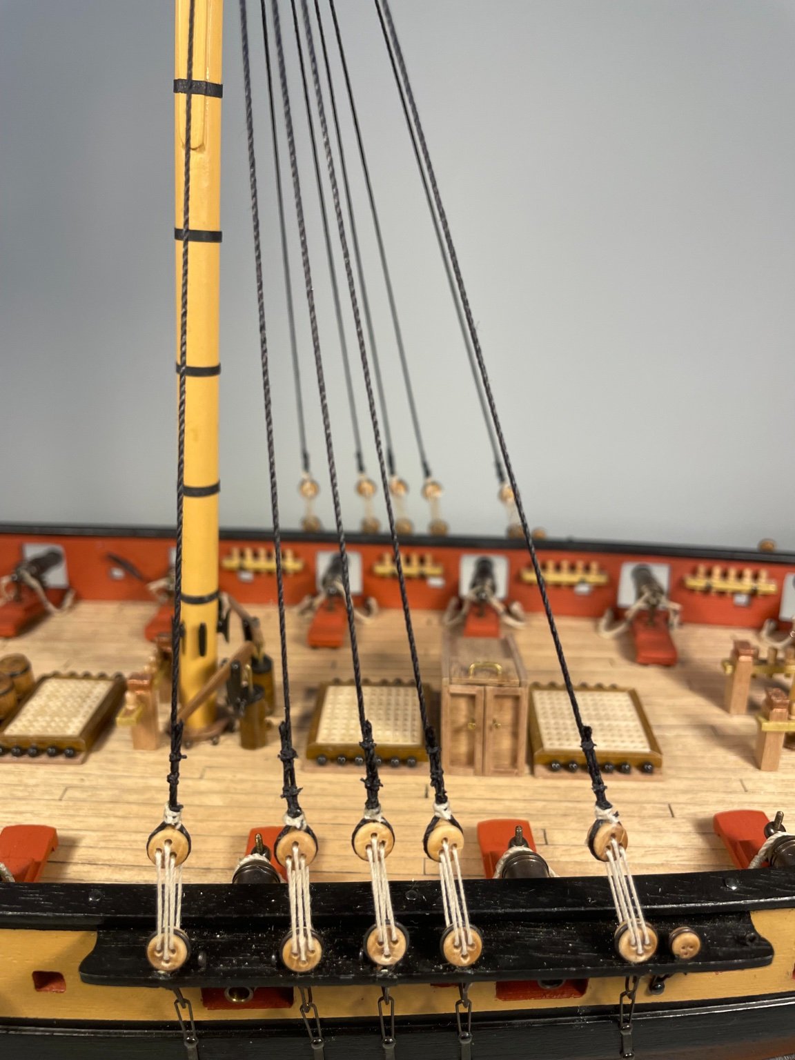
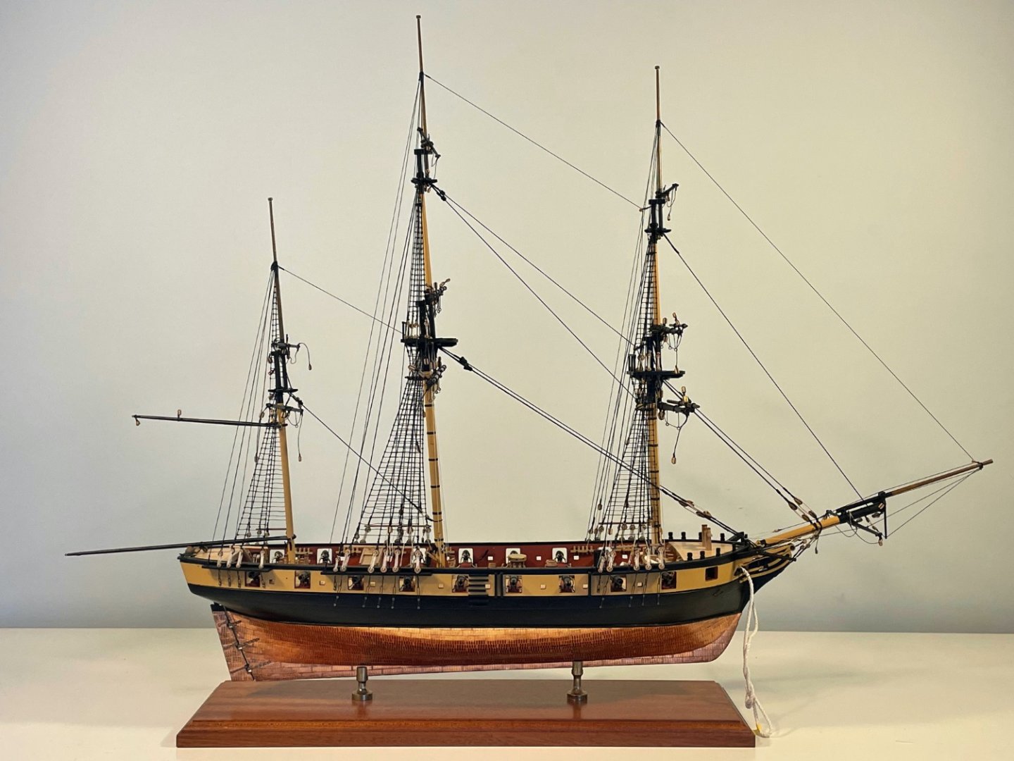
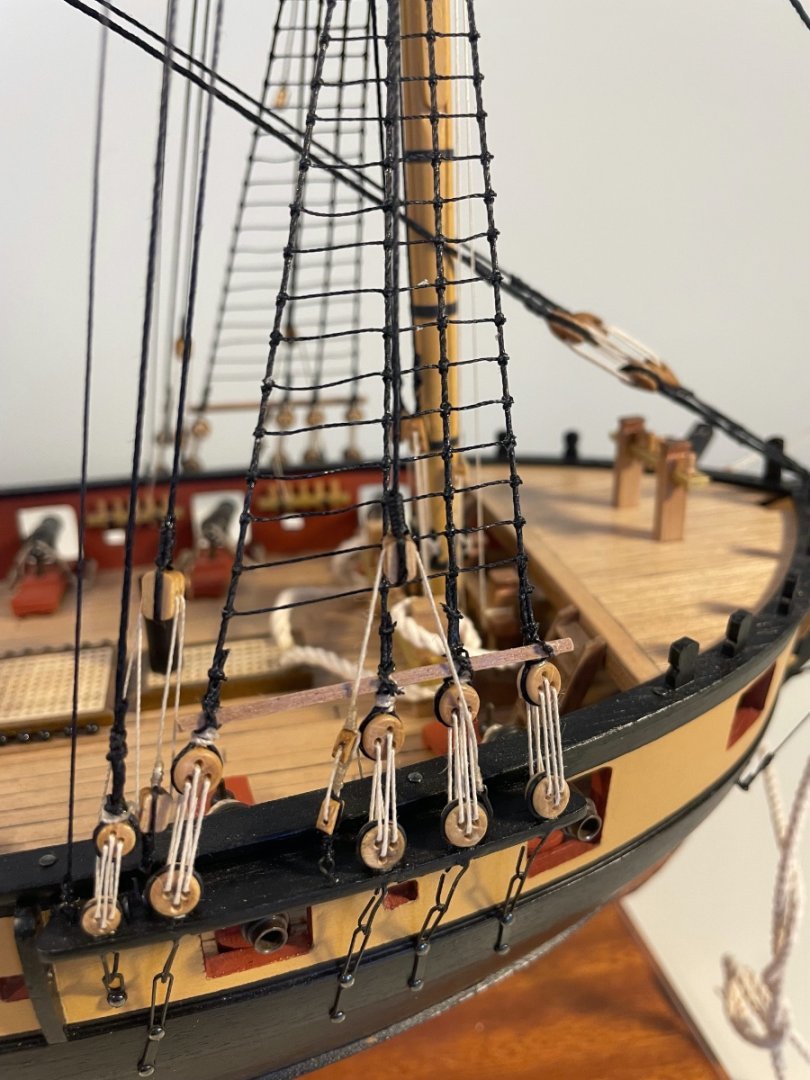
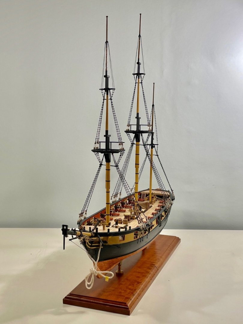
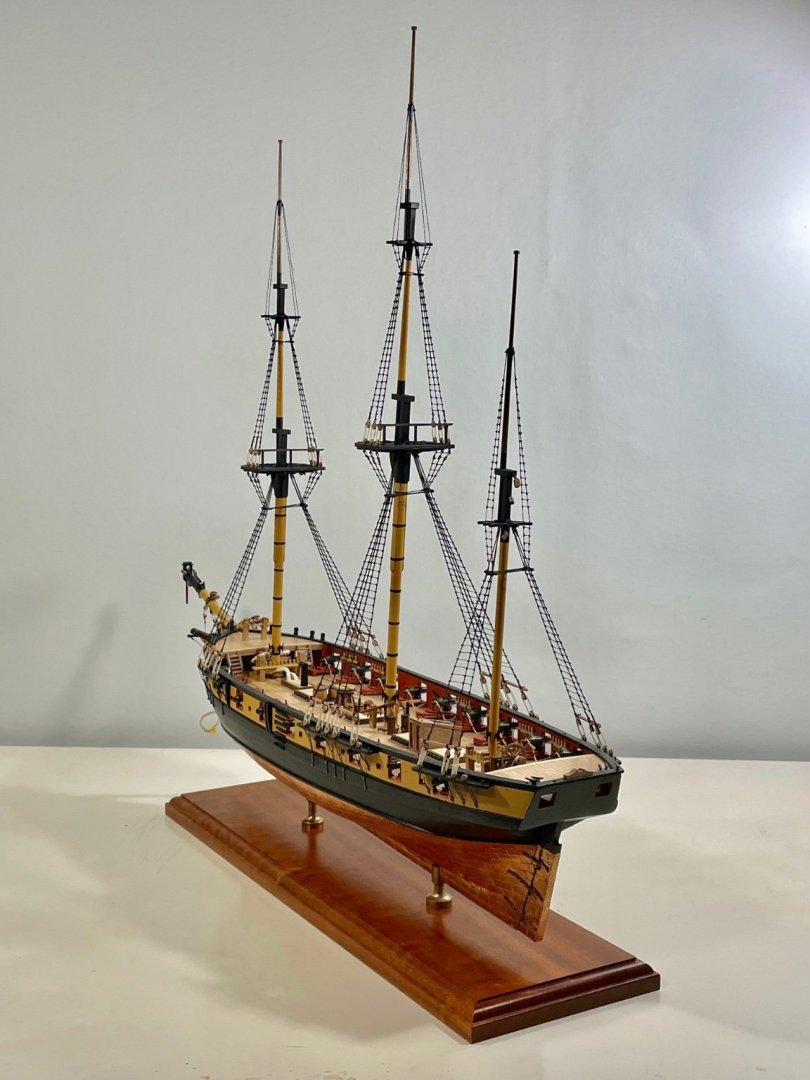
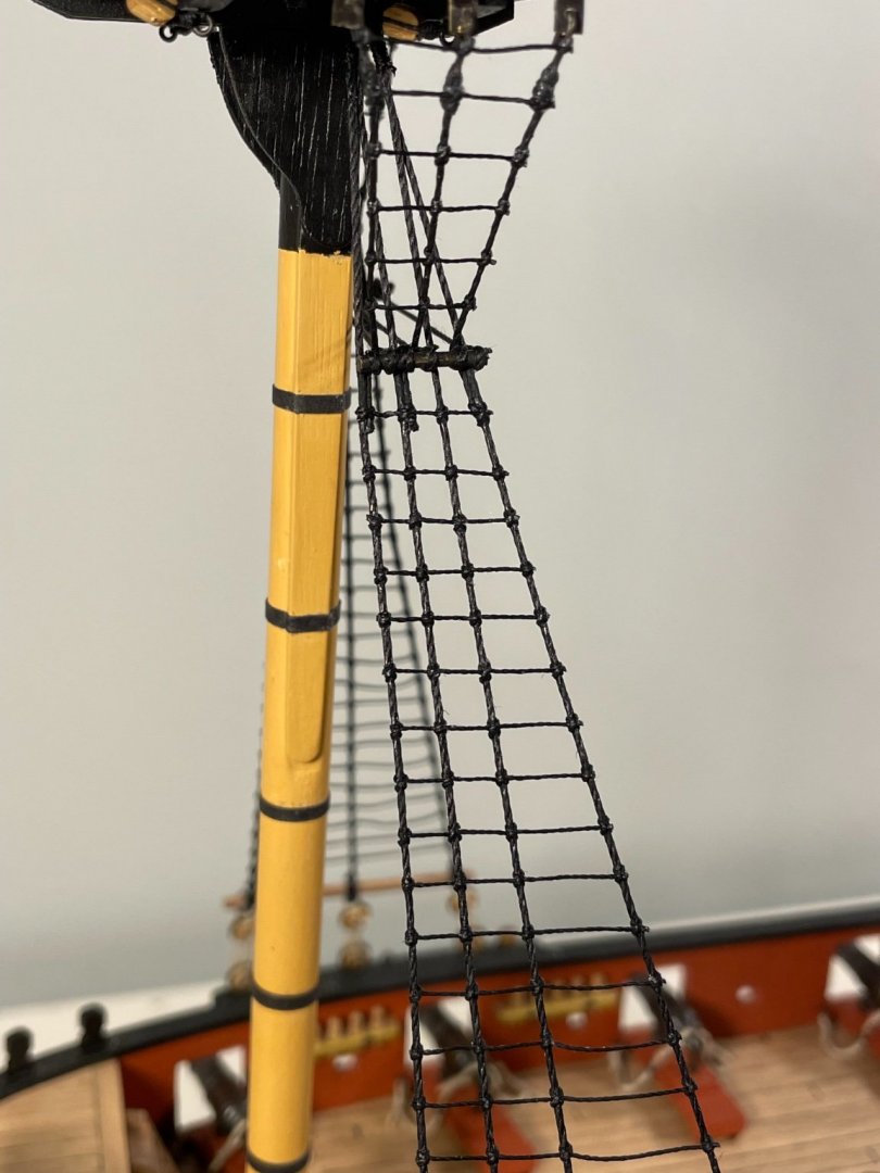
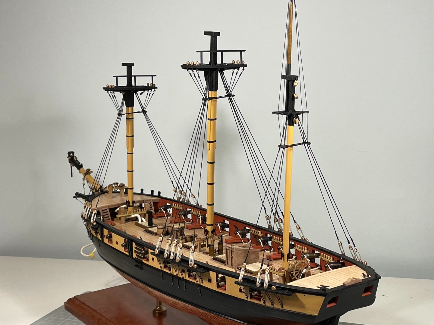
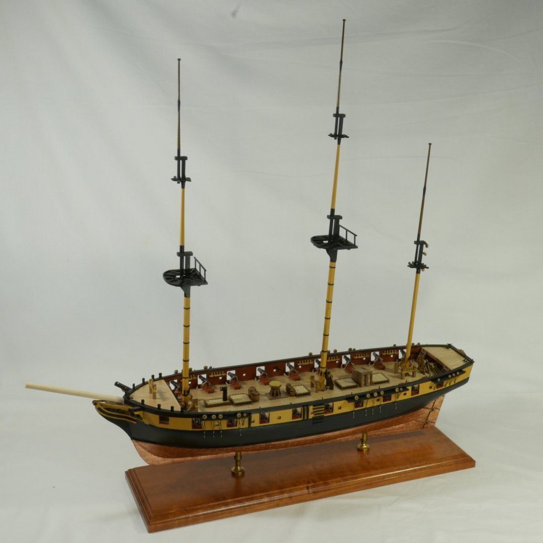
Shrouds rattled down! Quite a job - but the end result is certainly worthwhile I think - and anyway, what option is there? The authorities agree that ratlines were space at about 1 ft apart, so at 1:64, about 5 mm. That's convenient because I could use 5 mm graph paper to show the spacing and keep the lines parallel. Here she is with the paper held in place and me about to learn how to tie clove-hitches quickly. In the background you can see Petrejus open with an illustration of deadeyes, shrouds and ratlines showing. Also shown in that illustration is a "sheer batten" sitting just above the deadeyes. When I looked at this pic, I came to the view that the whole effect would be better with a batten so I fashioned some from 2 mm-square walnut Here you can see the starboard lower ratlines with the sheer battens in place And here, several weeks later, is the finished result, and a close up I fond this pretty tough-going to start with, getting the tension right and tying the knots off took quite a while to learn. But that surely, is at the heart of satisfaction in model-ship building: working out what to do is fun, but doing it requires skill, and skill you have to learn. I flatter myself that I now have the skill of tying clove-hitches in 0.25 mm thread; I certainly should since I tied 908 of them. On the subject of thread, the kit provides natural thread and breezily suggest that it be dyed, with a brush using india ink, after installation. What could possibly go wrong? I bought some of Caldercraft's black thread, and while its springiness was annoying, it looks fine. From memory there were 900 copper plate to attach, and tying these knots was quite reminiscent of the labour of sticking on the plates. Slow to start, deft to finish. I am delighted with the overall effect. I think the of the Cruizer class as workmanlike, rugged and un-flashy vessels, but with masts rigged, Snake looks really quite graceful.
- 109 replies
-
- 8
-
-
- snake
- caldercraft
- (and 1 more)
-
Lots of nice little details.
-
Thanks for those comments - pics hide the defects (nearly), but I’m pleased with progress.
-
All shrouds and catharpins rigged, and masts stepped. Ratlines next.

- 109 replies
-
- 7
-
-
- snake
- caldercraft
- (and 1 more)
-
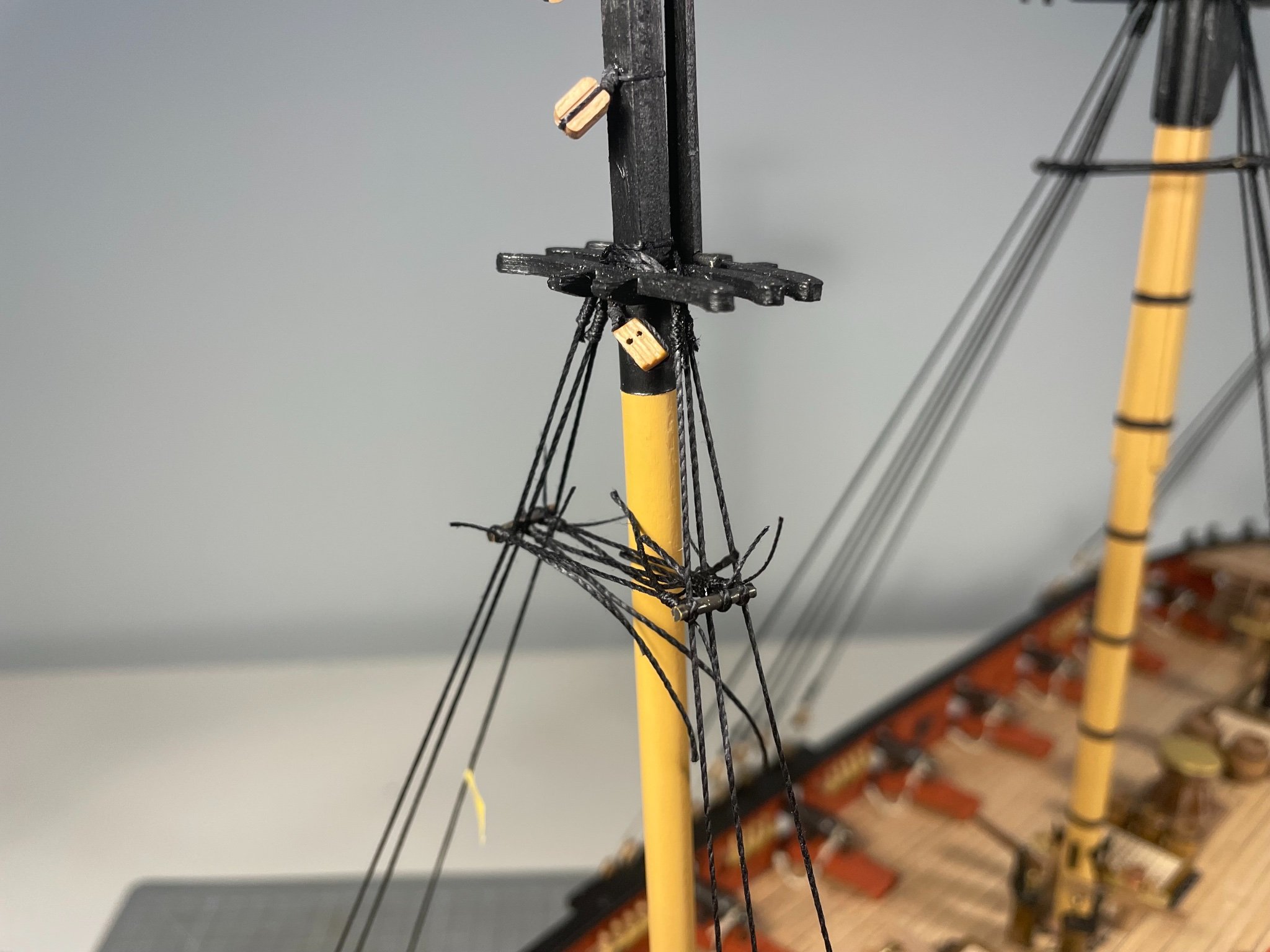
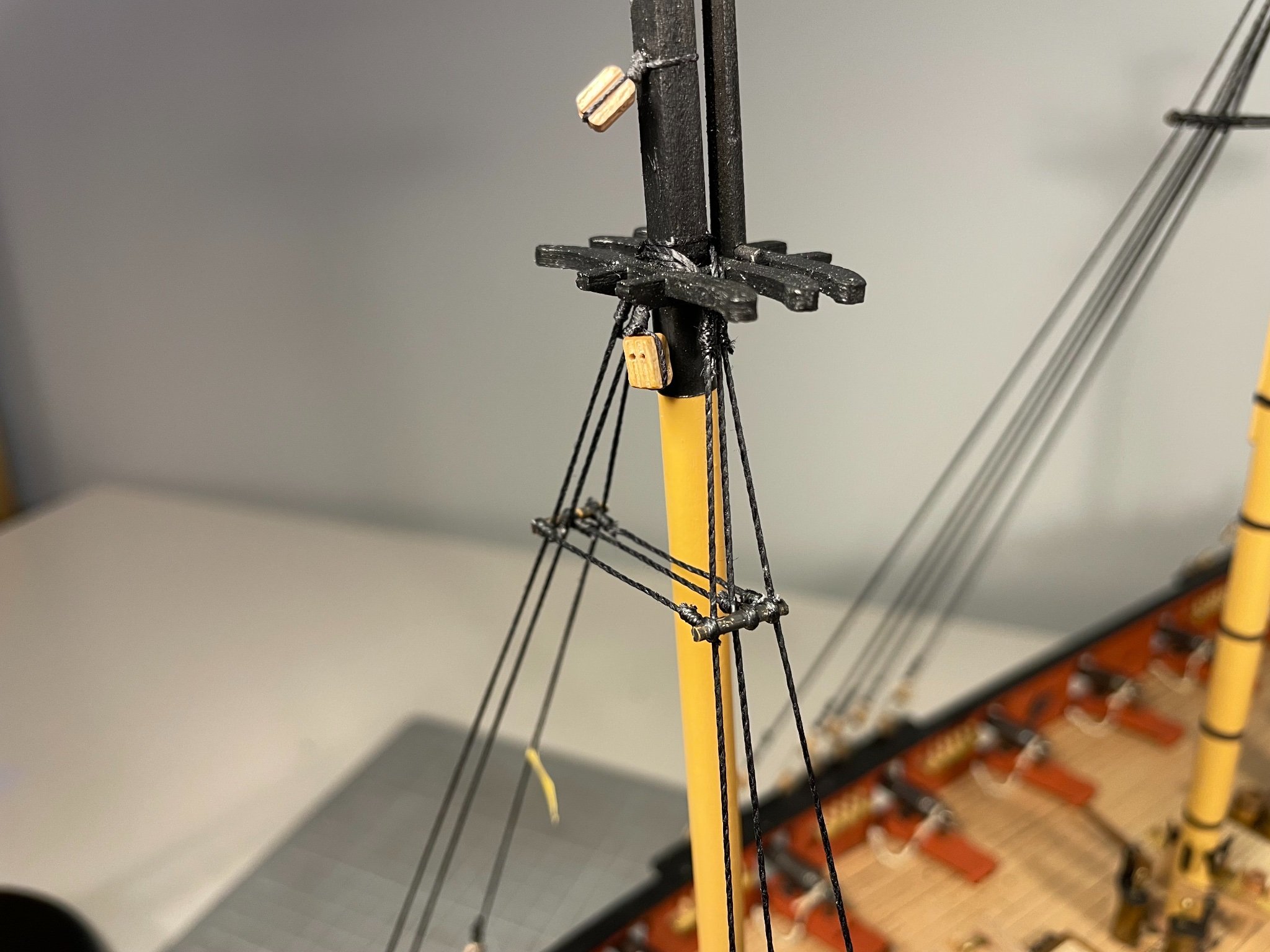
Futtock Shrouds and Catharpins Had an exciting week tying tiny knots in impossible places. First step was to install futtock staves - made from 2 mm brass rod, blackened chemically and then cut to length. I marked the height with tape and then tacked the staves with a single spot of CA, clamping them briefly with alligator clips. I pre-seized the catharpins And because the stave was only tacked in one point could slide them into place and then pull them tight More than a little cross-eye inducing. But after very careful trimming the results seemed satisfactory to my eye Here's the whole set for the lower masts But probably the most exciting part of the whole week was the decision to install futtock plates so that I could use hooks to attach the shrouds (as seen above and below) . I made the plates from the scrap brass perimeters of the PE sheets, drilled 0.8 mm holes and then glued the plates and the deadeyes at the same time with CA. Futtock shrouds were only difficult because tying them off required negotiating the catharpins and the shrouds. I am beyond delighted with the appearance of the hooks, and reasonably pleased overall. Lessons for me were: shroud tensions need to be uniform to get neat symmetrical, horizontal parallel staves. Seizing the futtock shrouds to the main shrouds is a mugs game - I undid the first attempts at seizings and just glued them - I might revisit that when I do the ratlines - seizing over the glued shrouds. Because I installed the catharpins before the futtock shrouds I hadn't appreciated that the catharpins need to avoid the side of the shroud to which the futtock is to be attached. Depth perception when confronted with 5 shrouds, three futtock shrouds and three catharpins, all mirrored by another set on the other side of the mast (so thats 22 thin black lines) is a challenge, so go slow, don't force things and be very, very careful with the snips. Next could be ratlines, lower yards or upper mast shrouds. Would be interested in others' views, but I think it best to go with the masts, as yards and ratlines will restrict access.


- 109 replies
-
- 4
-
-
- snake
- caldercraft
- (and 1 more)
-
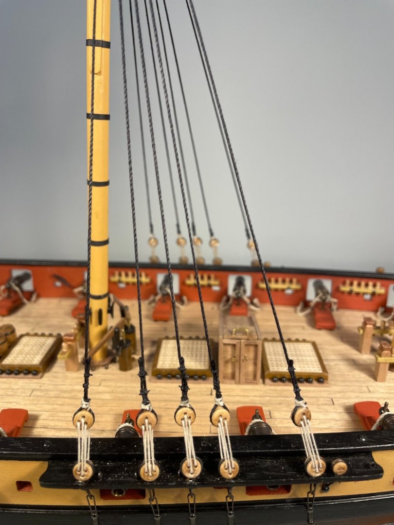
Shrouds I rigged the lower shrouds a fortnight ago, and after a weekend in Whitby, and the excellent museum there, have just about rigged the futtock shrouds as well. As guided by the minimal insturctions I made small wire spacers to set the upper deadeyes a reasonably constant distance from the lower. As the photos show I also put some pins in to stop the deadeyes from rotating Seizing ropes is much easier off the ship than on so I made up pairs of shrouds like this with a single loop to go over the mast and one for each deadeye. I then fitted the top loop over the mast and pulled the seizing tight. The two lower loops then went over the deadeyes and I pulled the shrouds and seizing tight - easy to say, harder to do. Not too tight, though, and reasonably uniform for all the shrouds on a given mast. It was slow going at first but over time repetition made it easier: I found that in order to get any tension I had to anchor the knots with CA rather than PVA, though I then top-coated with the latter (diluted) to give a smooth overall appearance. Tying off the shrouds at their lower end with clove hitches was virtually impossible with the very springy 0.25 mm black thread, until I discovered that soaking it and the shrouds in diluted PVA reduced the springiness. It's all a learning curve.


- 109 replies
-
- 4
-
-
- snake
- caldercraft
- (and 1 more)
-
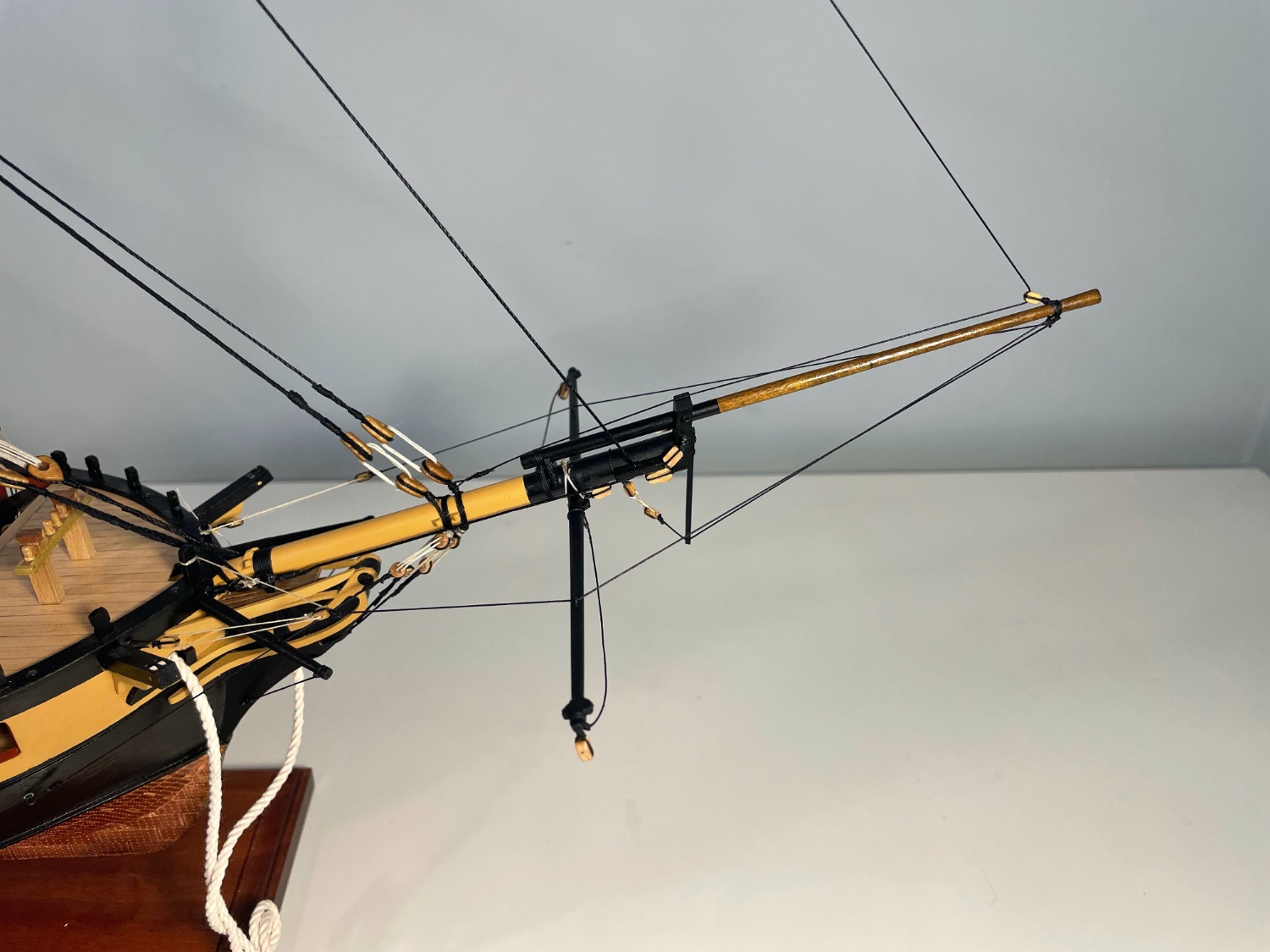
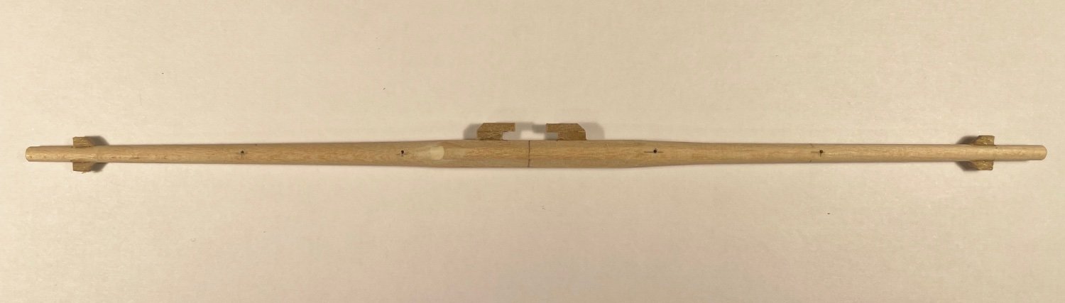
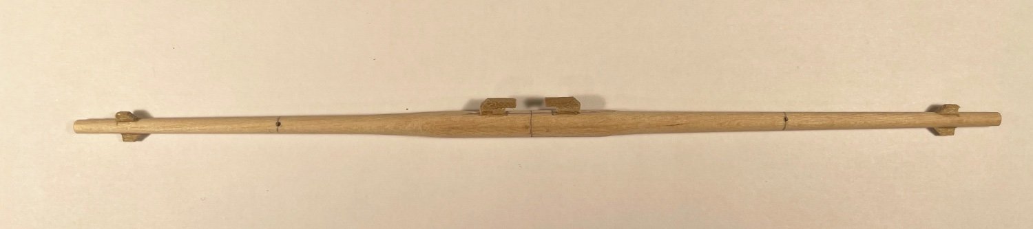
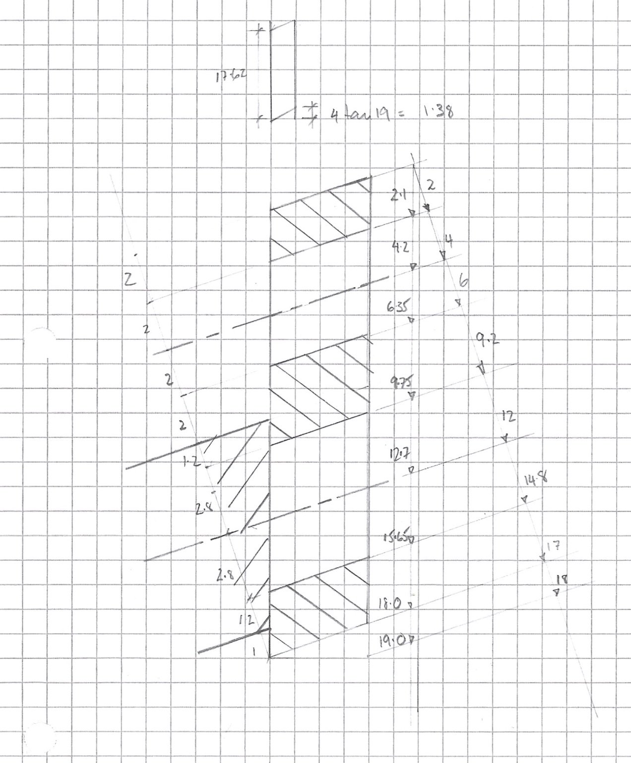
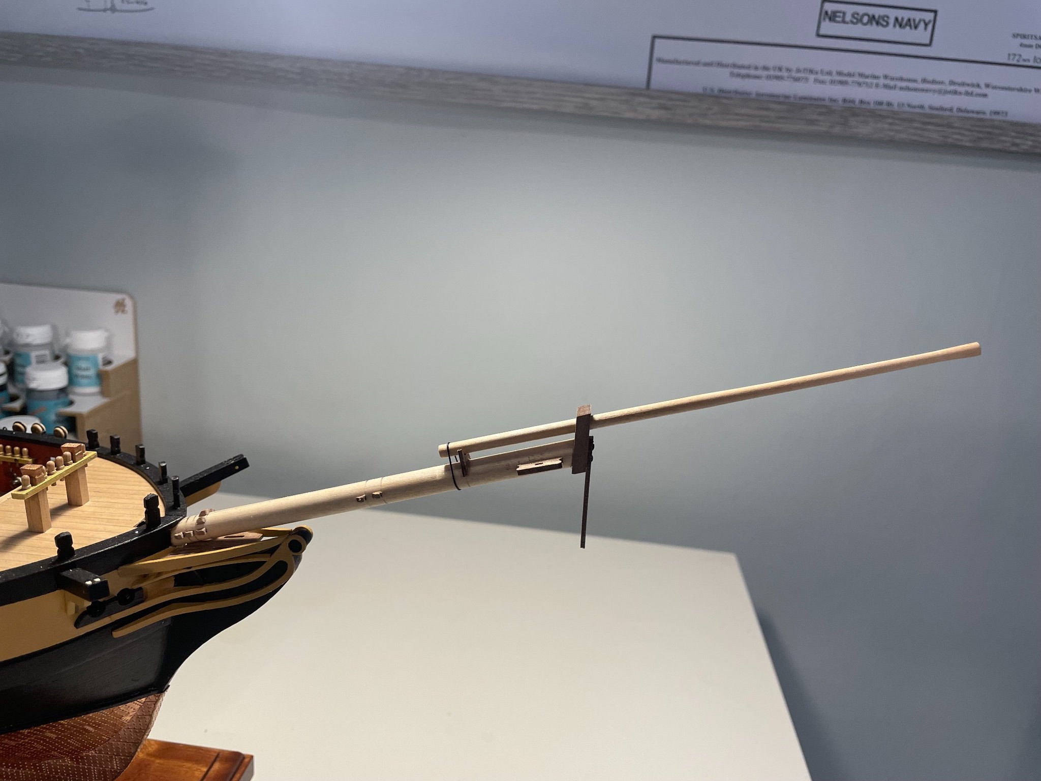
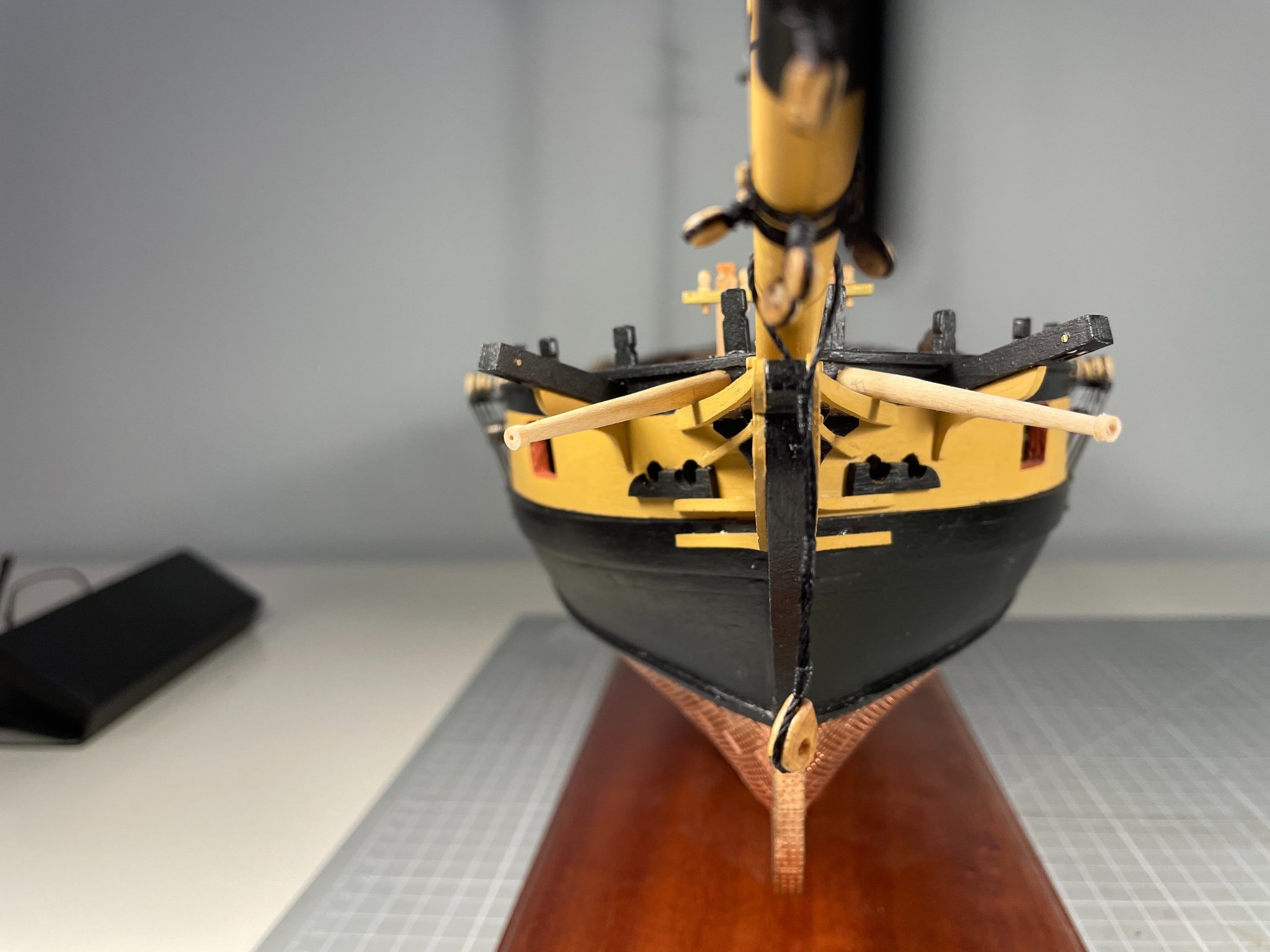
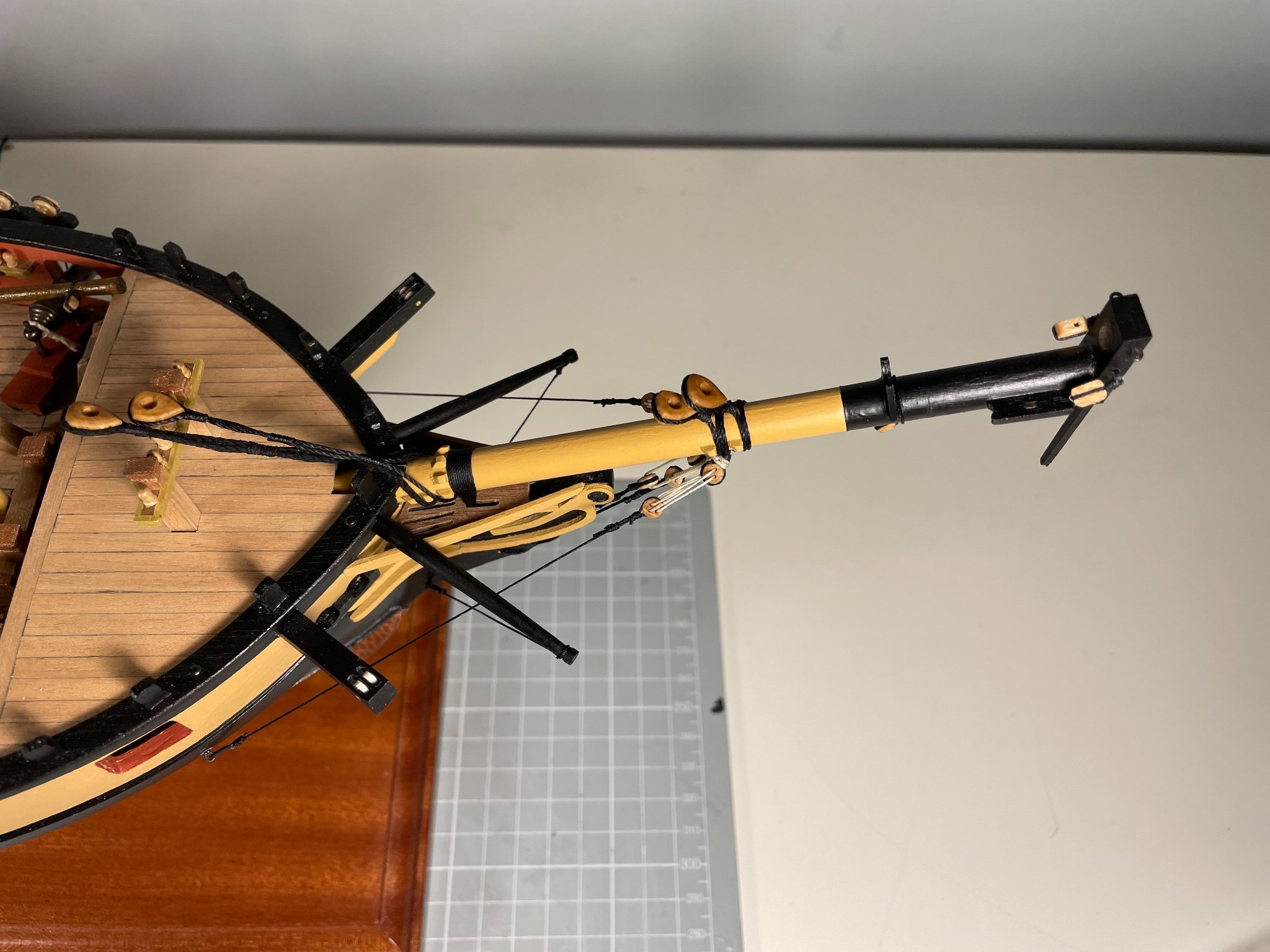
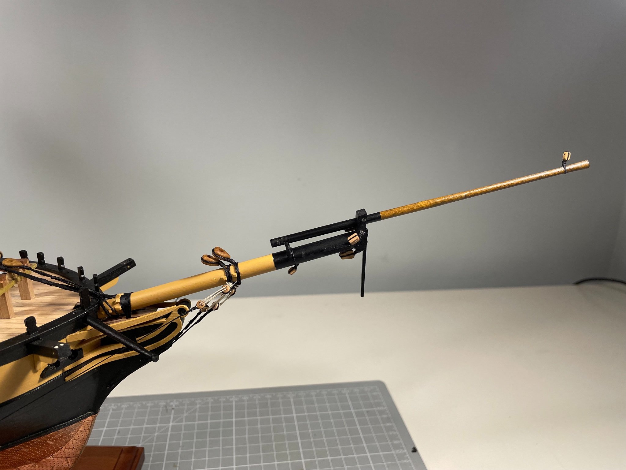
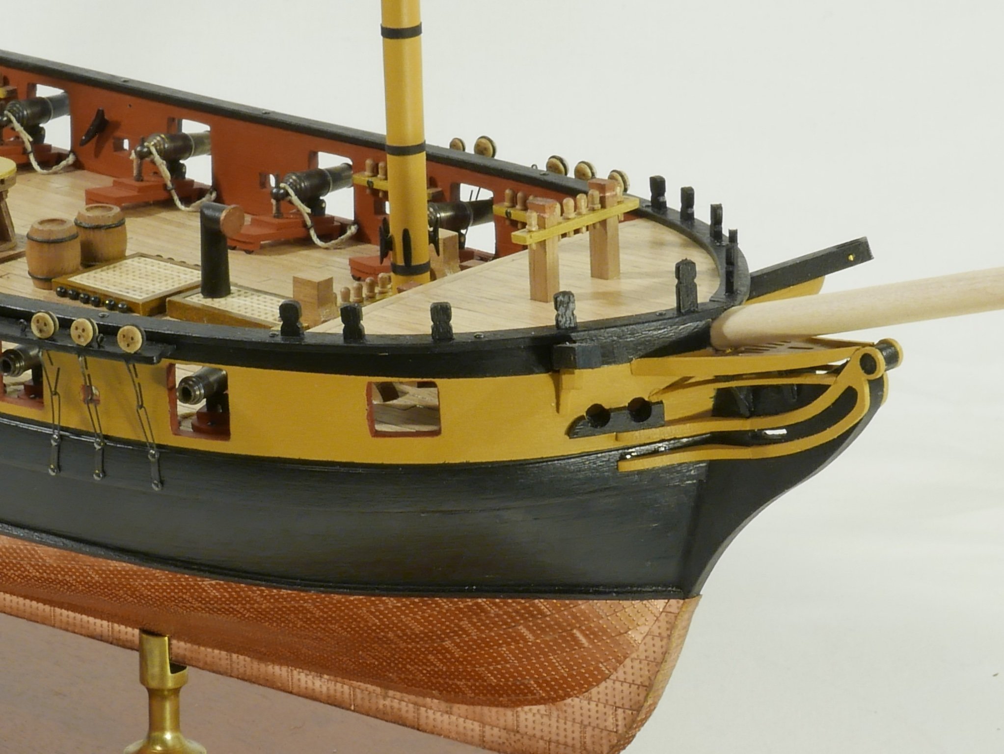
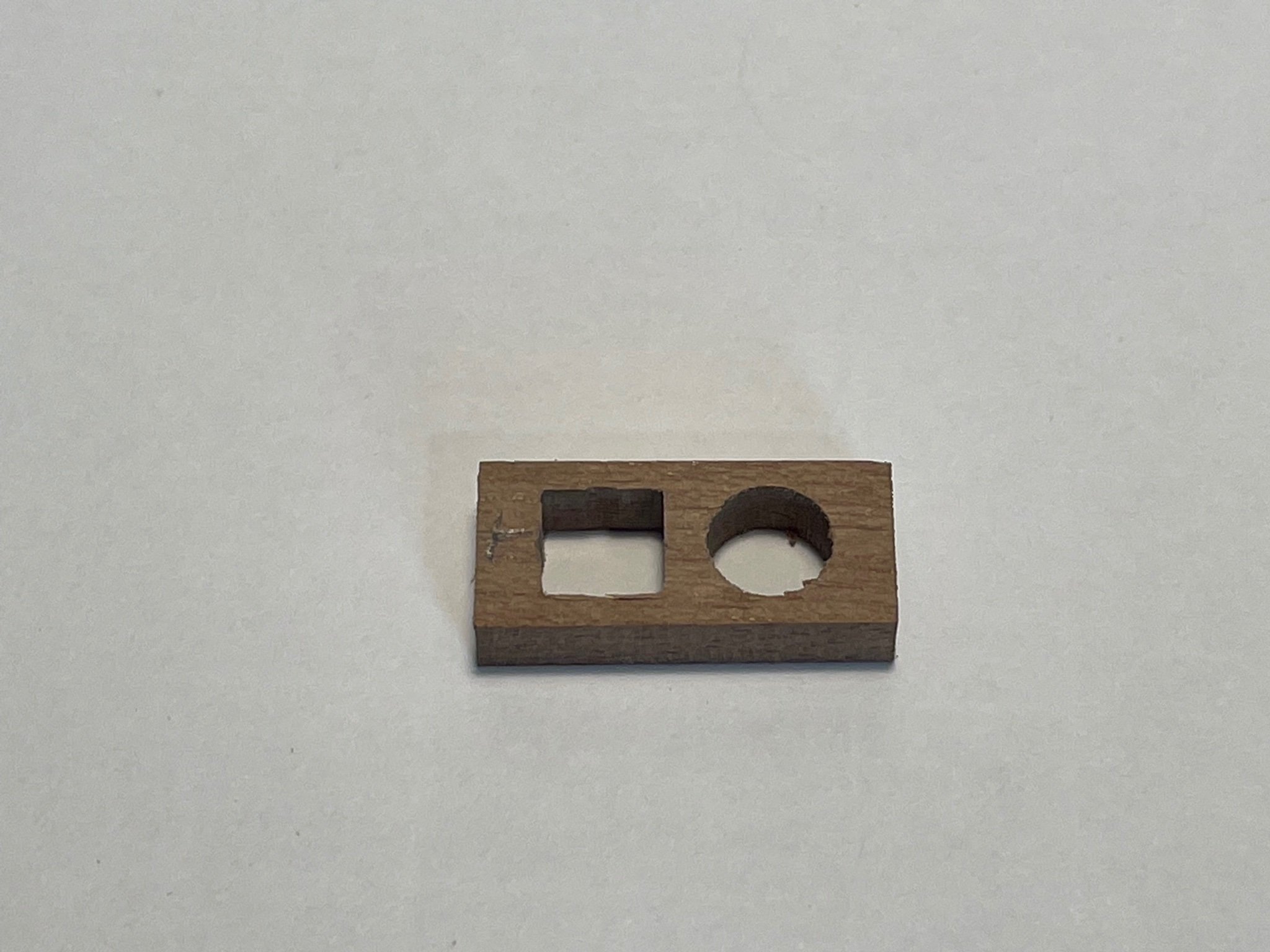
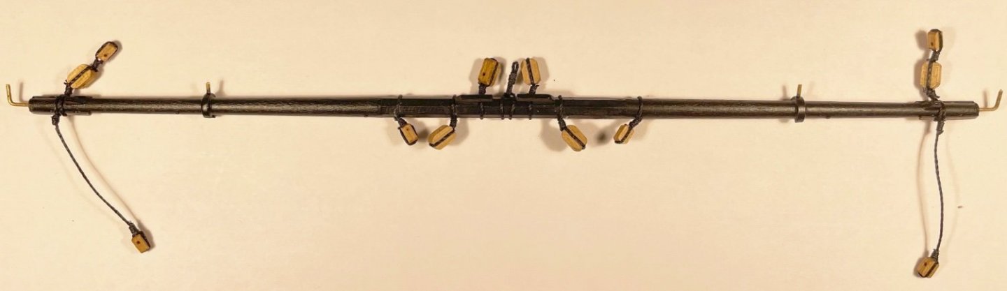
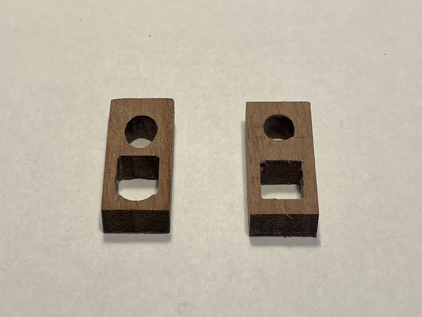
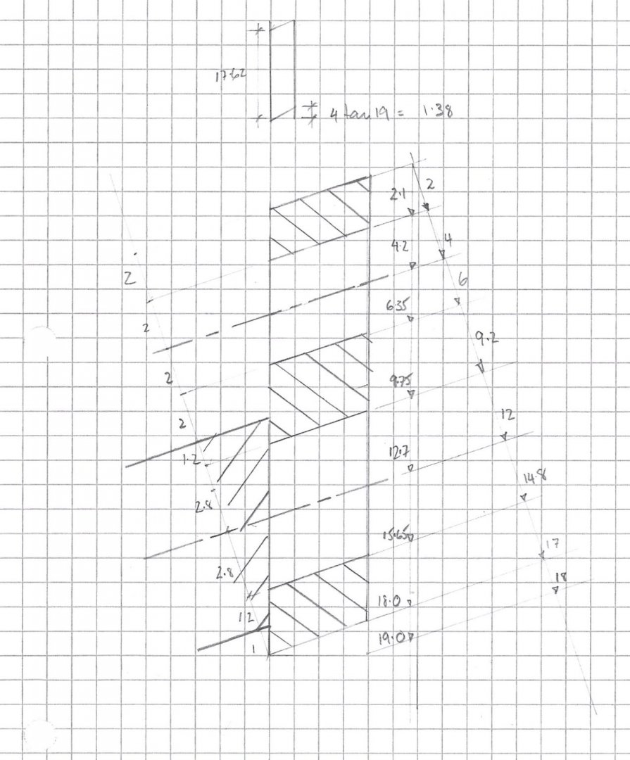
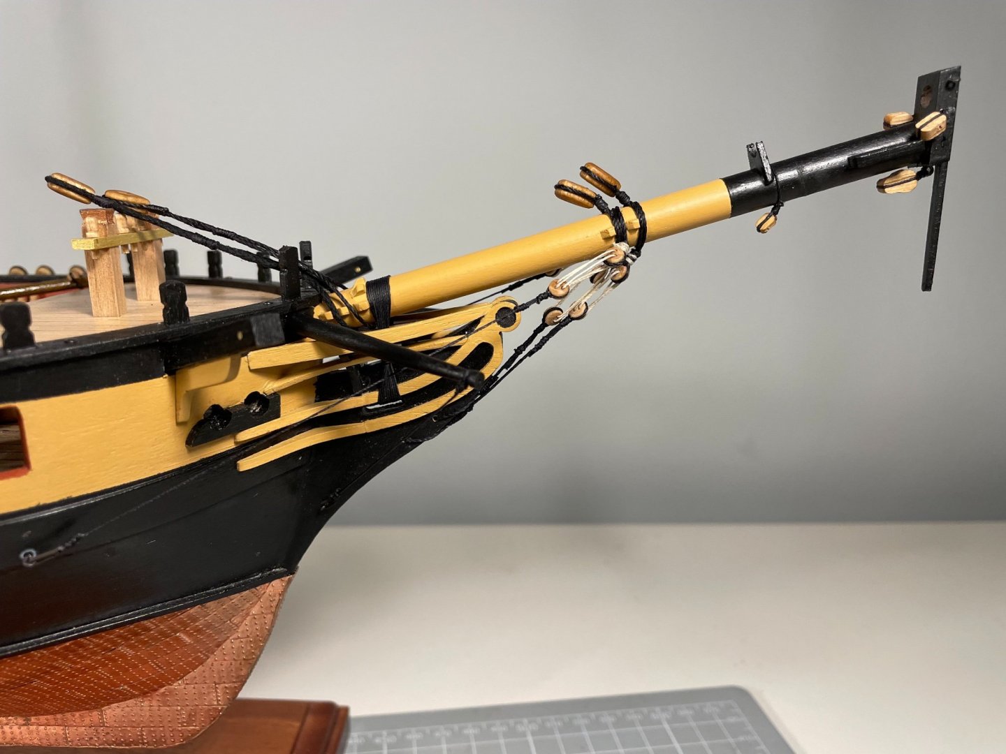
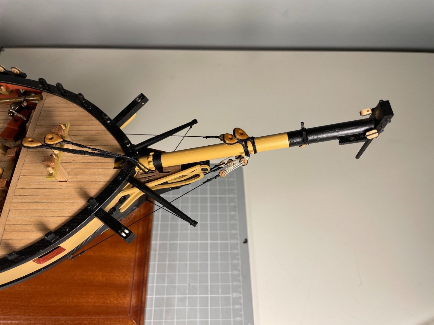
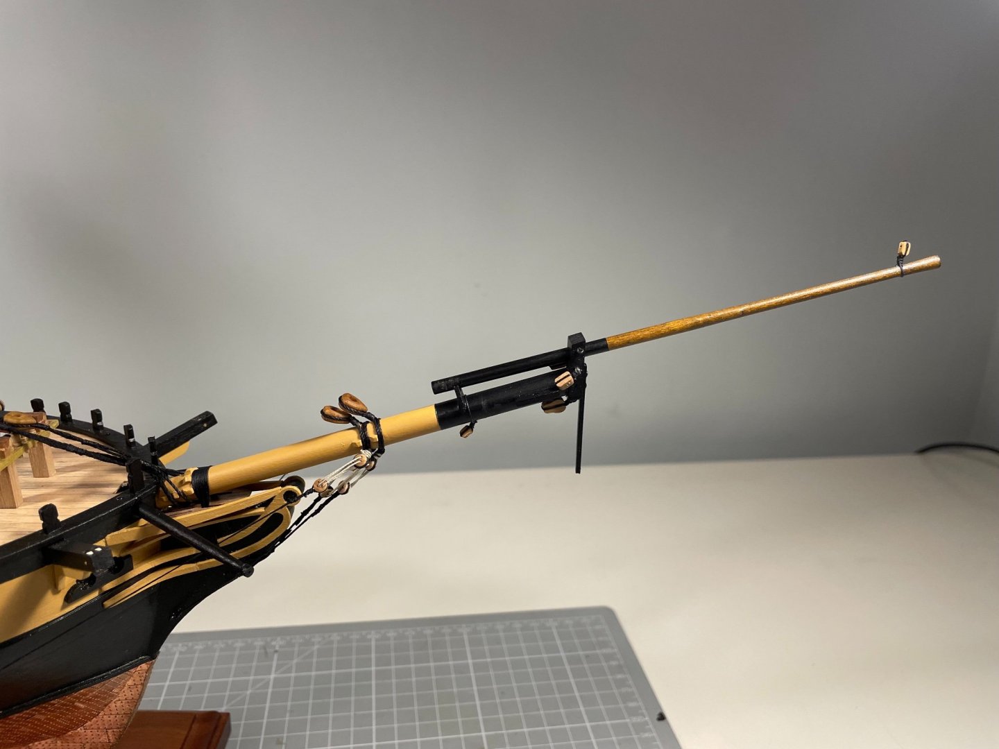
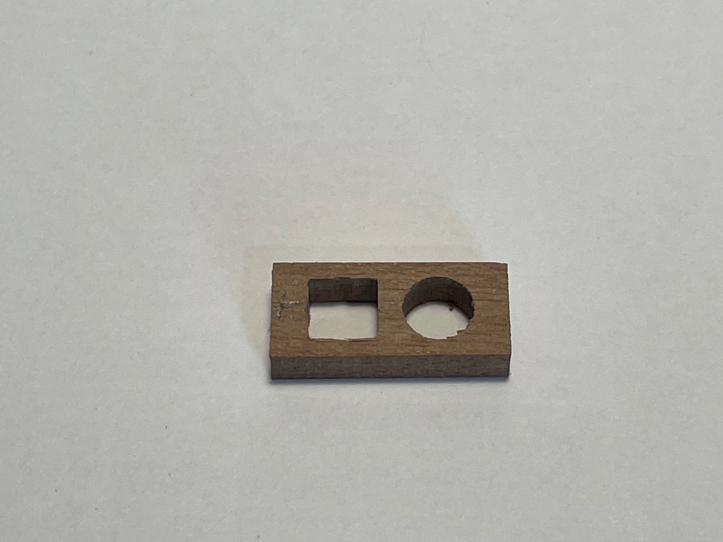
Bowsprit and Jib Boom The bowsprit was remarkably fiddly, but gave lots of learning so I'm reasonably pleased. The bowsprit requires 13 cleats and a bee to be placed reasonably carefully. This I did by machining shallow slots using my Proxxon mill. I took the photos below after I had fitted the cleats, but the slot for the bee is visible. The square tenon to take the cap can also be seen. Machining that was relatively straightforward though the undercut on the top surface was a tittle tricky Far more tricky was the cap itself. As has been remarked before, the kit-provided part with two circular holes bored perpendicular to the surface is virtually useless. In the picture below, on the LHS you can see what happens when you machine a square slot for the tenon - it is not possible to fit the square slot around the circular hole (I did the geometry - but I'll spare you that). On the RHS is the cap I scratch built. Easy to machine, hard to design, so here's my sketch of the cross-section - crucial to that was determining the angle of the bowsprit (19º above horizontal), and the width of the jib boom seating bracket (2 mm). Here it is assembled (with interim gammoning around the boom) Bumkins added Painted and rigged - with Petrejus's "hour glass" gammoning.


- 109 replies
-
- 5
-
-
- snake
- caldercraft
- (and 1 more)
-
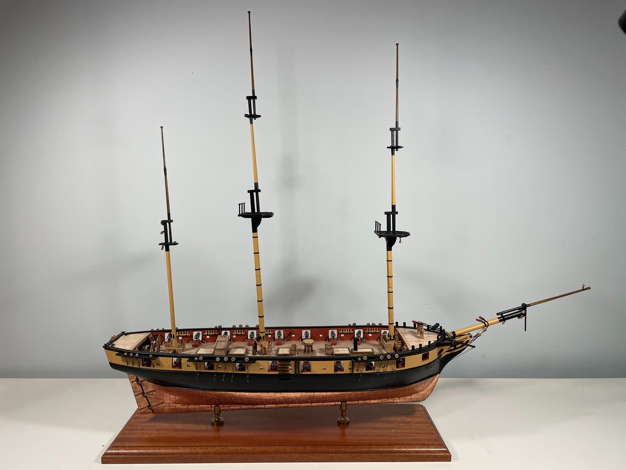
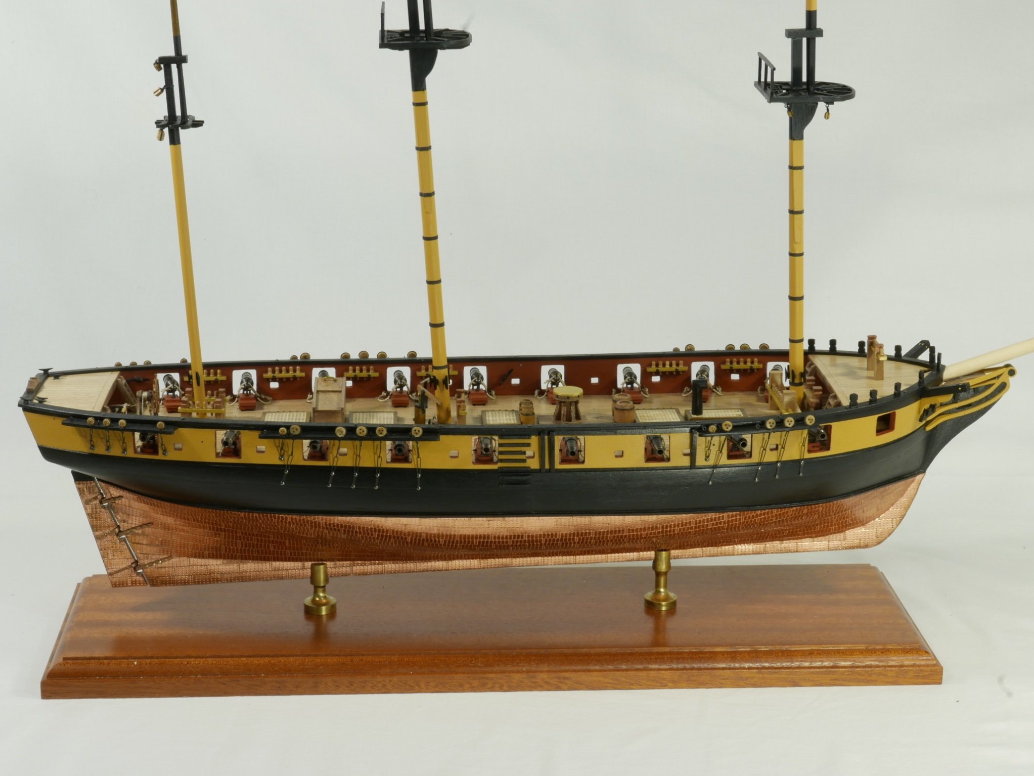
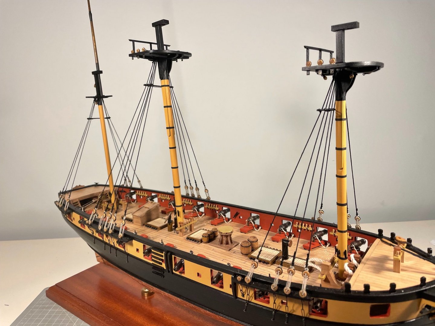
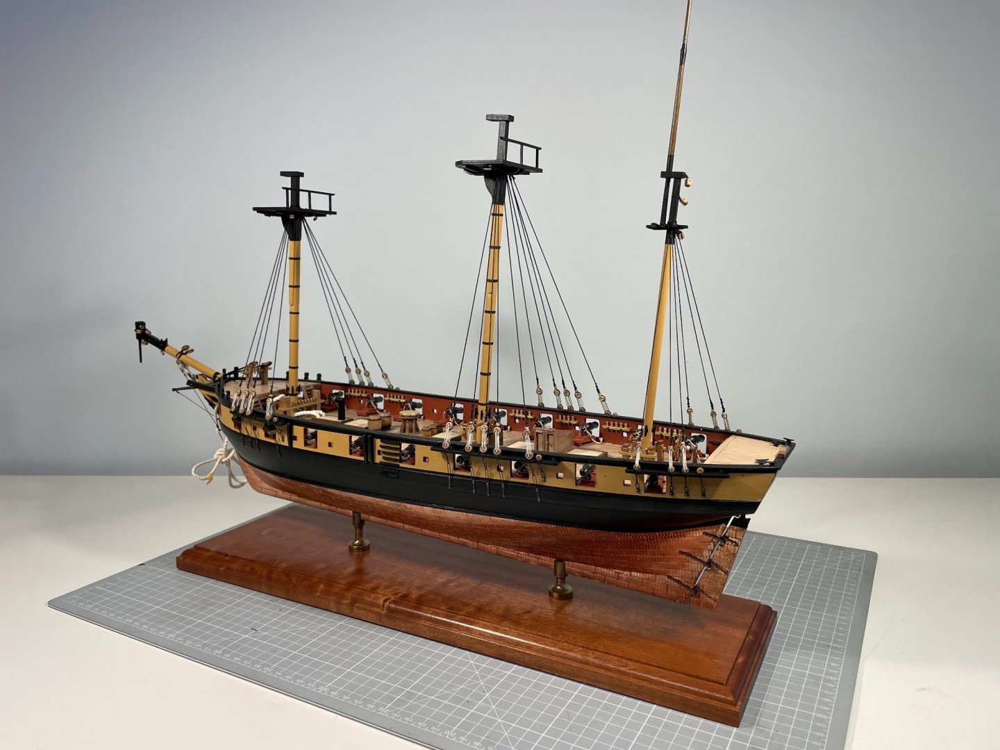
Seems I've not been on here for a while. That's mainly because I retired from work a month ago, but the Admiral only retired this week. That gave me a month to get back on my bike and do some ship building, but not much appetite to sit at a computer and update this build log. So here's the update - all five components of the masts are built, painted and installed, and all the lower deadeyes are in place. I found the deadeyes quite frustrating as the metal loops they sit in were tricky to handle - opening them out to insert the deadeye always distorted them, so closing them back up again usually messed up the little loop in which the chain sits. I closed up the channels using some epoxy putty, which not only makes things seems stronger, it hides the mangled metalwork. Anyway, I got there in the end. Making the masts was reasonably straightforward with the usual mix of patience and tolerance of imperfections. Very glad I bought the Proxxon mill and lathe. The mill makes machining the square sections of the masts very easy and I even made the heels of the upper masts octagonal. That was a little tricky with 4 mm dowel, but once I bodged up a tailstock from the lathe to use on the mill, it worked ok Bowsprit next then perhaps some shrouds, and then the spars. Or maybe a mix of the two.


- 109 replies
-
- 5
-
-
- snake
- caldercraft
- (and 1 more)
-
That's excellent! It means I cannot distract myself from Snake by buying Sphinx, and must wait for a little time, during which Chris's plans for the future will doubtless grow. More importantly, it means that Chris's decision to go full time is vindicated and we can confidently expect Vanguard to go from strength to strength
-
Lovely to see such refined patient progress. Keep it up, Jason. Mike
-
Well any, or all? My heart shouts Indy - for her exploits under Pellew, for exemplifying the Royal Navy in the French and Napoleonic wars, for being the first ship of that period who’s name I knew (courtesy of CS Forester, when I was 12), but most of all for her muscular proportions and looks. My head says - where the hell would you put it, she’s huge? Heart wins this one. But heart also loves the detail of Sphinx, and Chris seemed to have doubts about doing that level of detail on a larger ship. But perhaps, seeing how Sphinxes have flown our the virtual pre-order door, doubts have also flown.
-
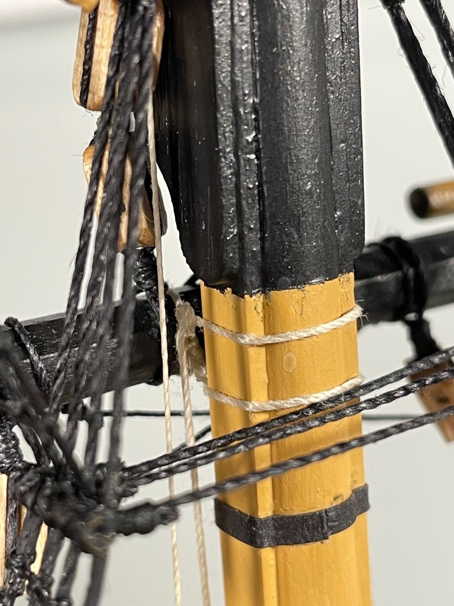
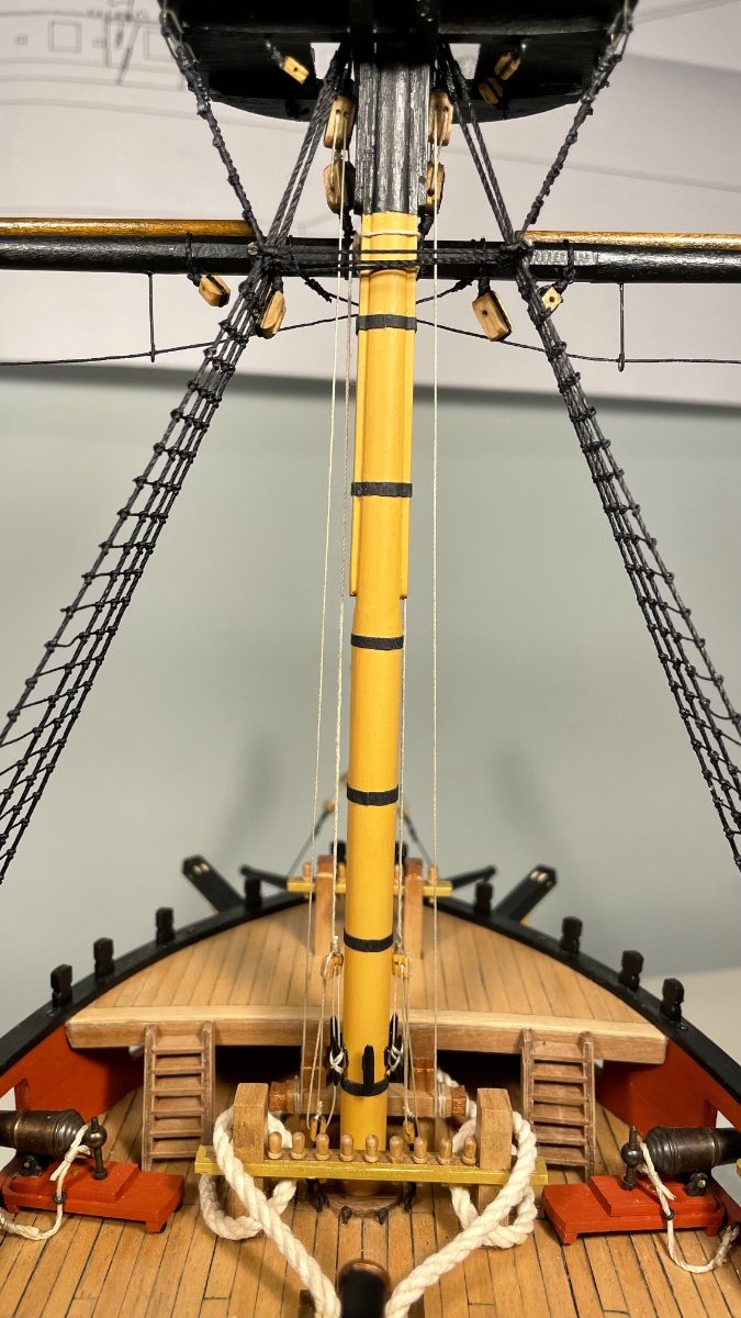
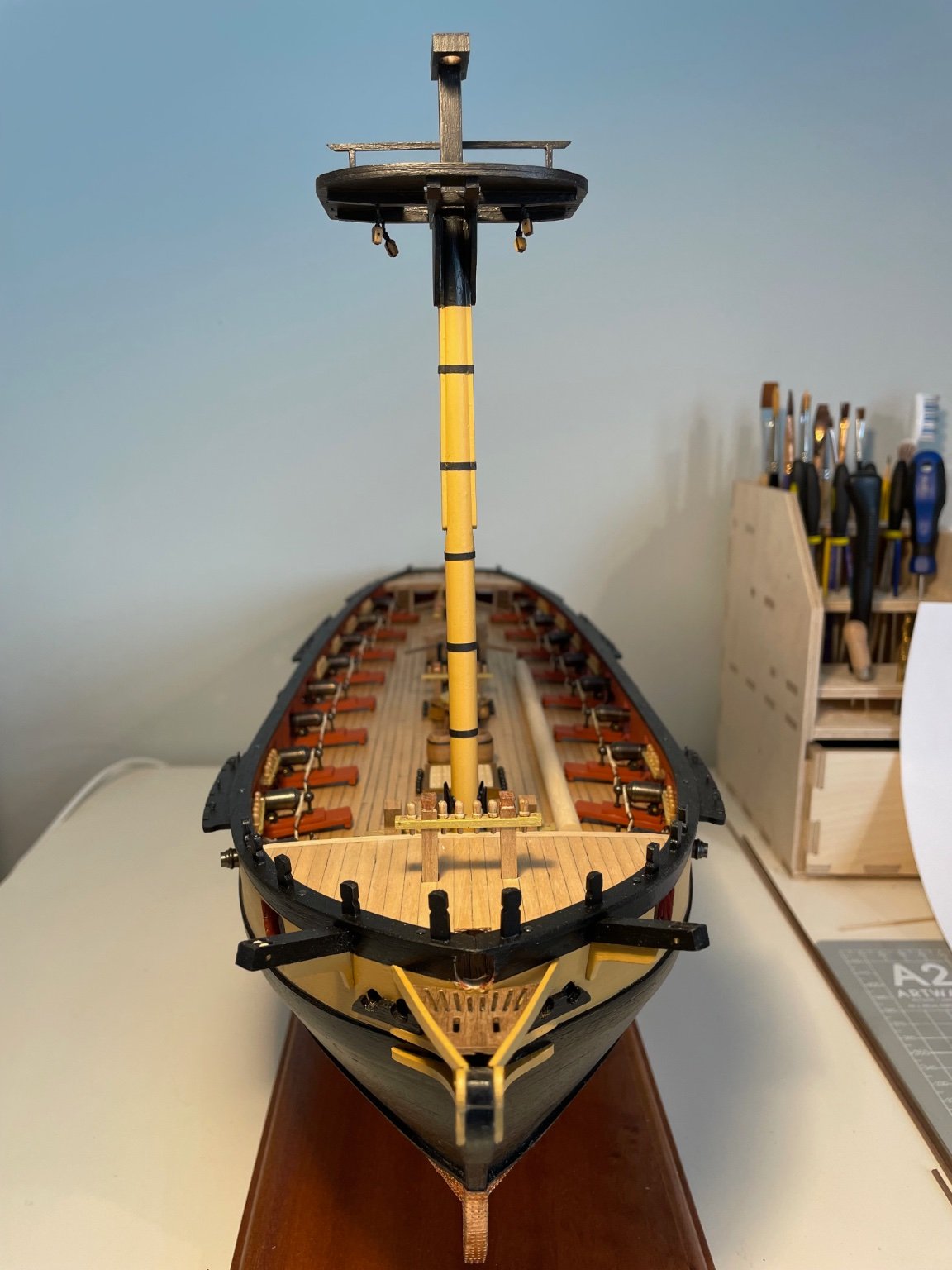
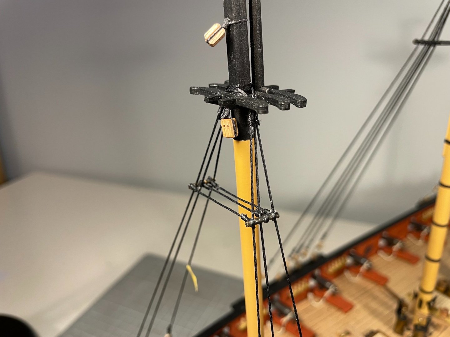
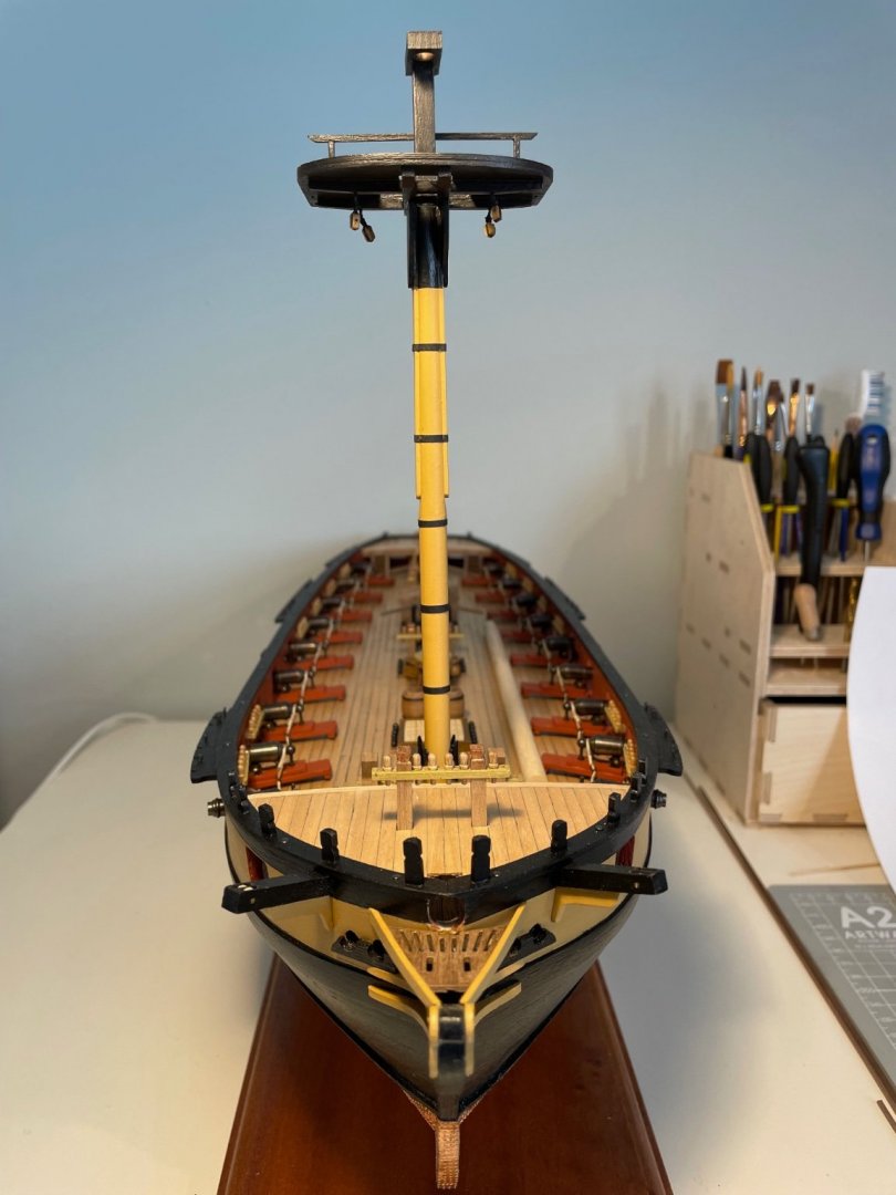
All that remains is to add the iron bands: reasonably straightforward using a method I saw elsewhere on this site - perhaps @James H - 2mm wide lengths of cartridge paper cut out. Tacked in place at 25 mm intervals on the after centreline of the mast using CA, wrapped around, trimmed to length, coated lightly with PVA, pressed on and held for 2 min. Scarcely a worry. Top tacked with PVA, seemed to sit square and parallel to the waterline (much shaping of the bibbs required at an earlier stage) Foremast swayed up! You can tell, I insist, that the mast has been tapered to take the cheeks And herre that the top sits on the bibbs You can even get vertigo Back when I have done another one or two.


- 109 replies
-
- 4
-
-
- snake
- caldercraft
- (and 1 more)
-
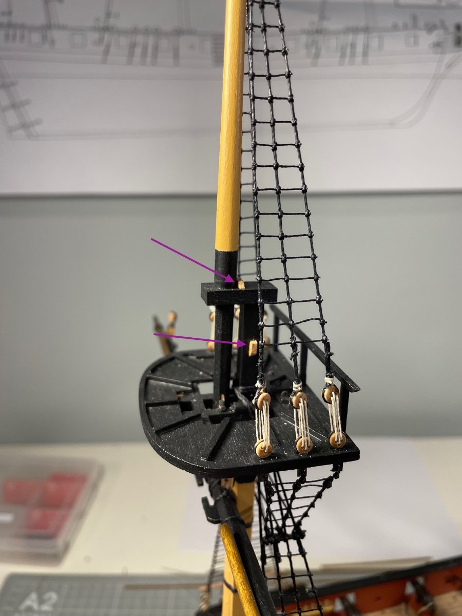
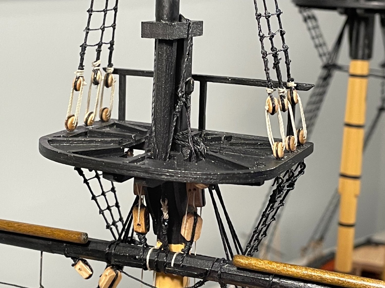
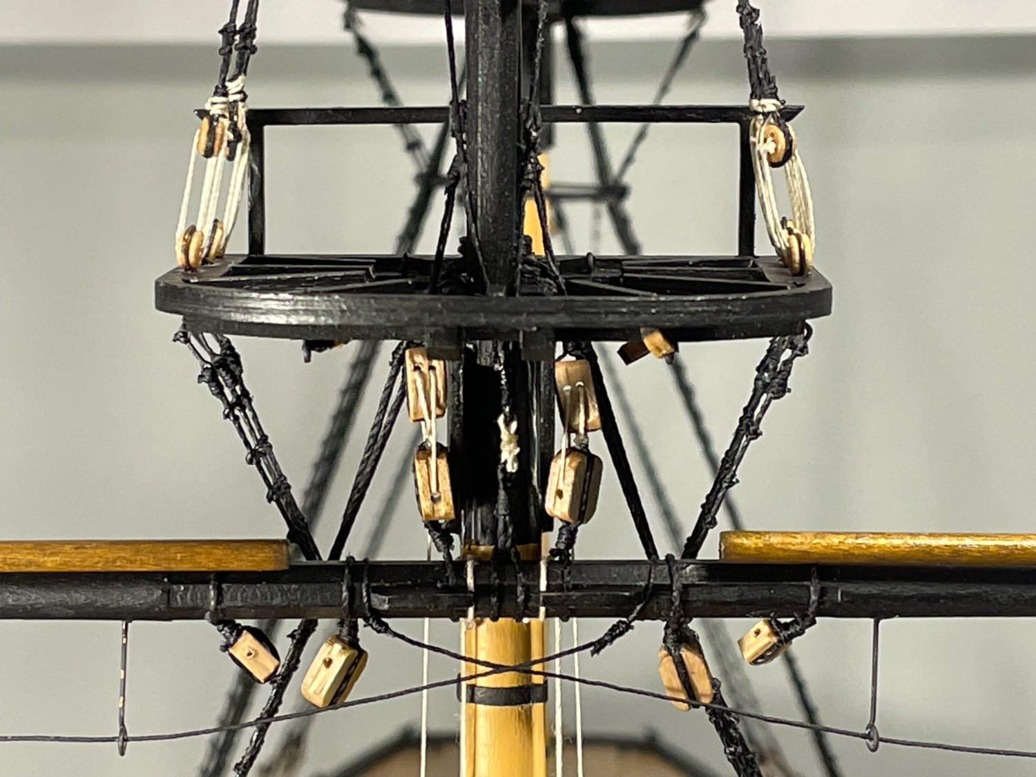
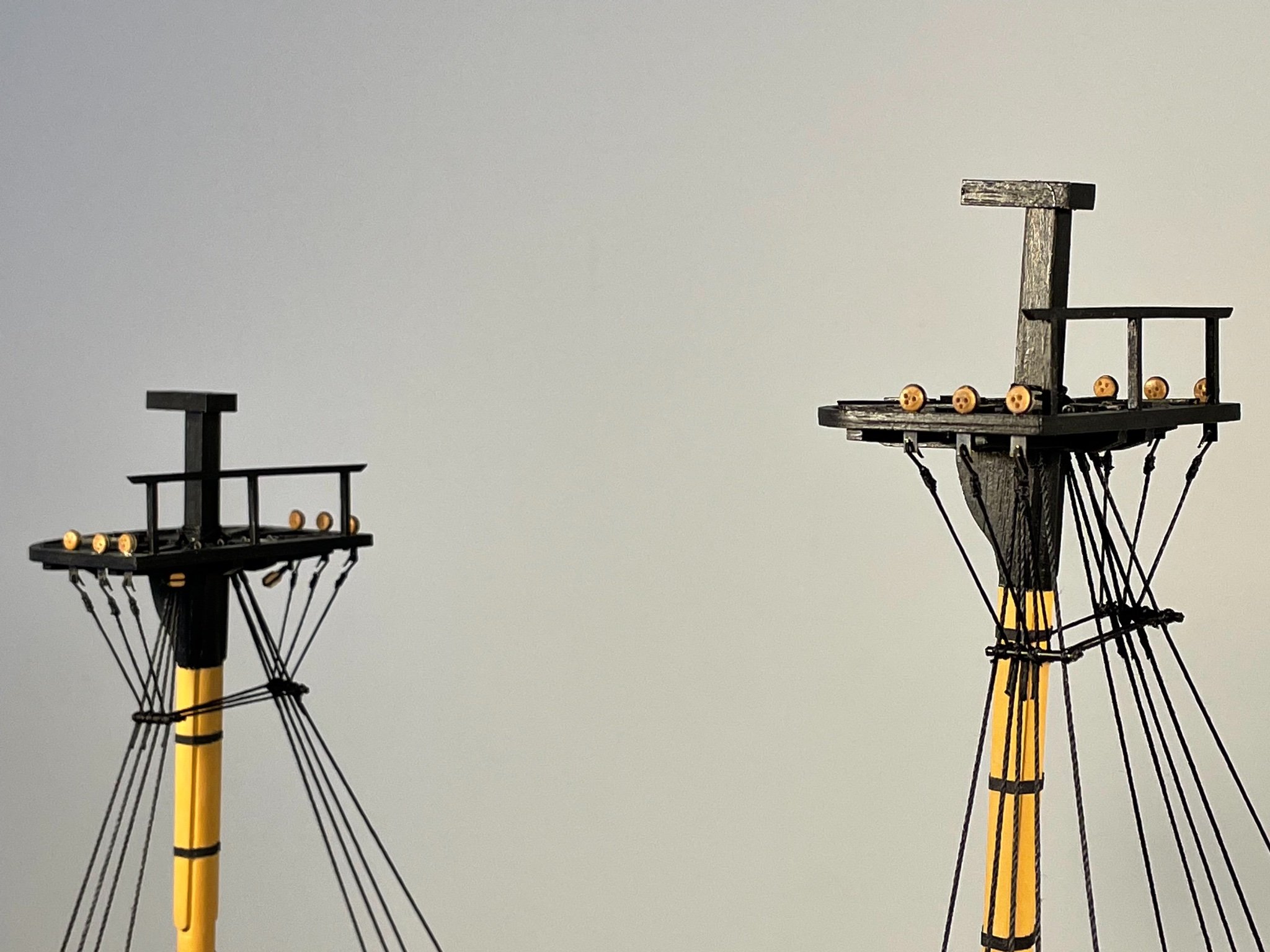
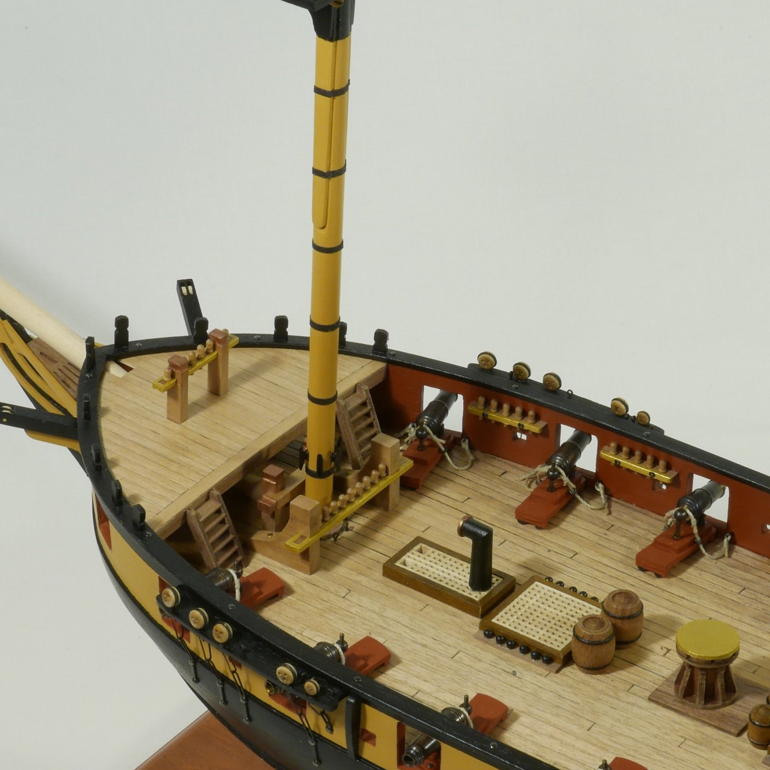
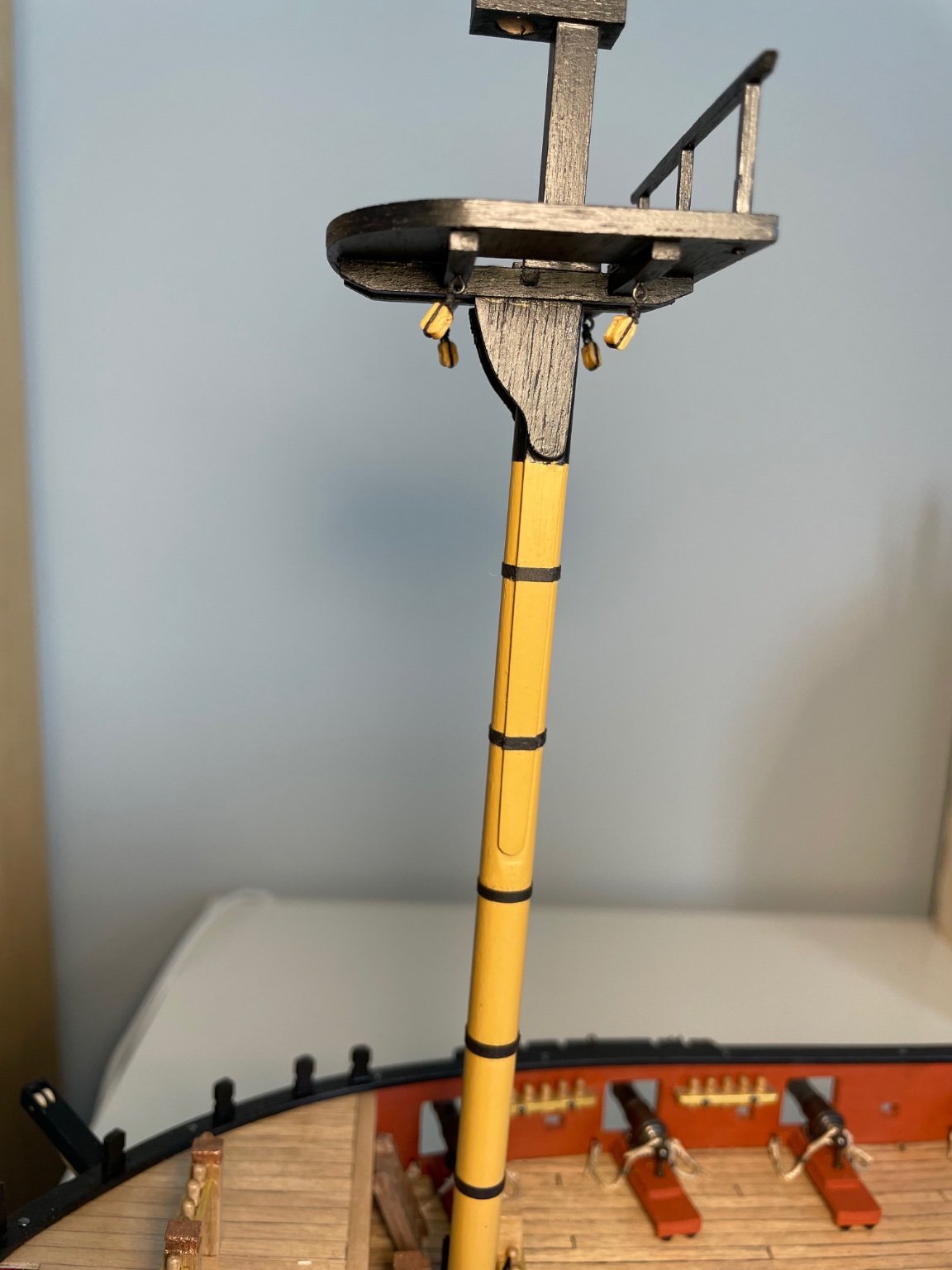
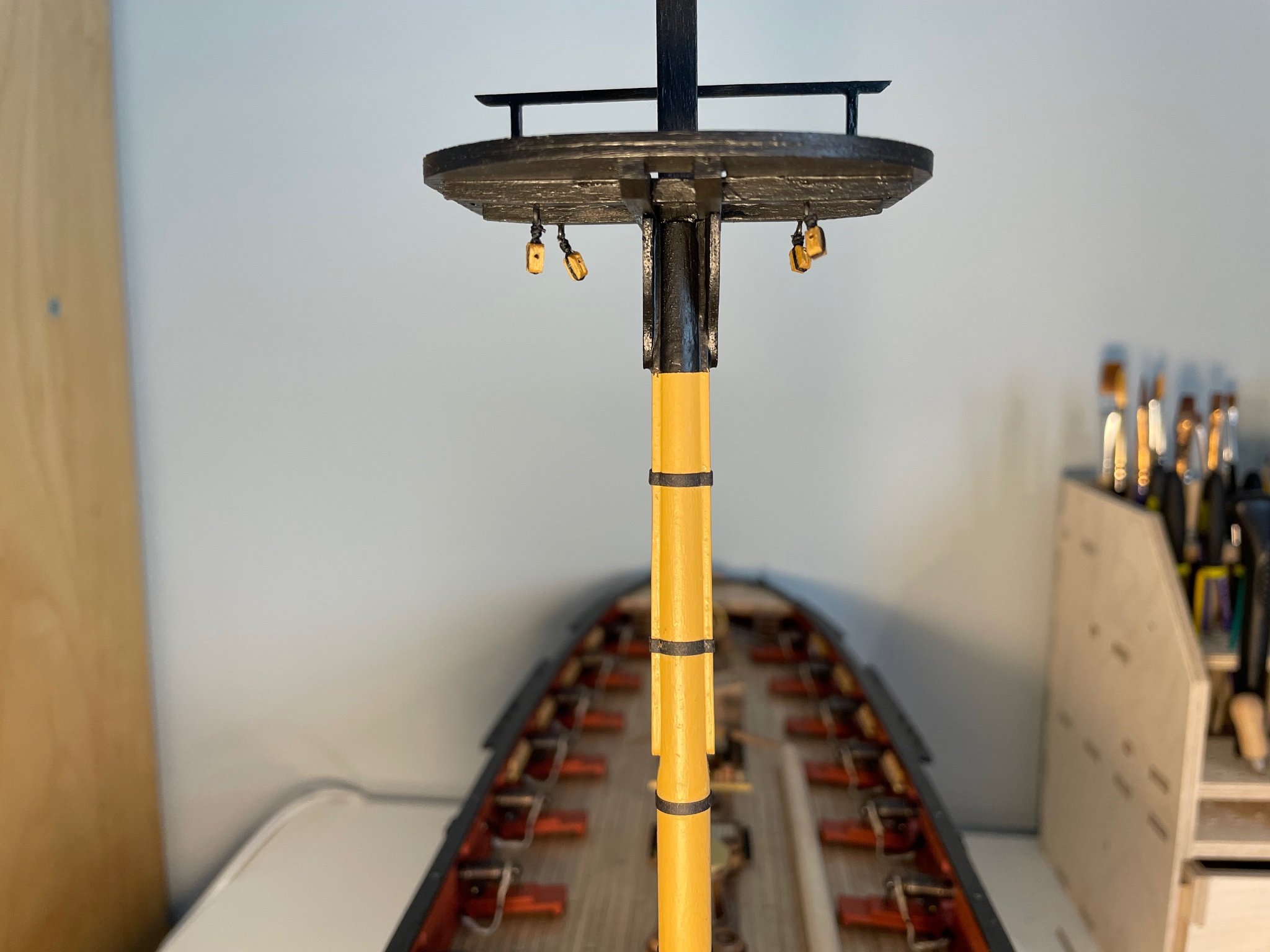
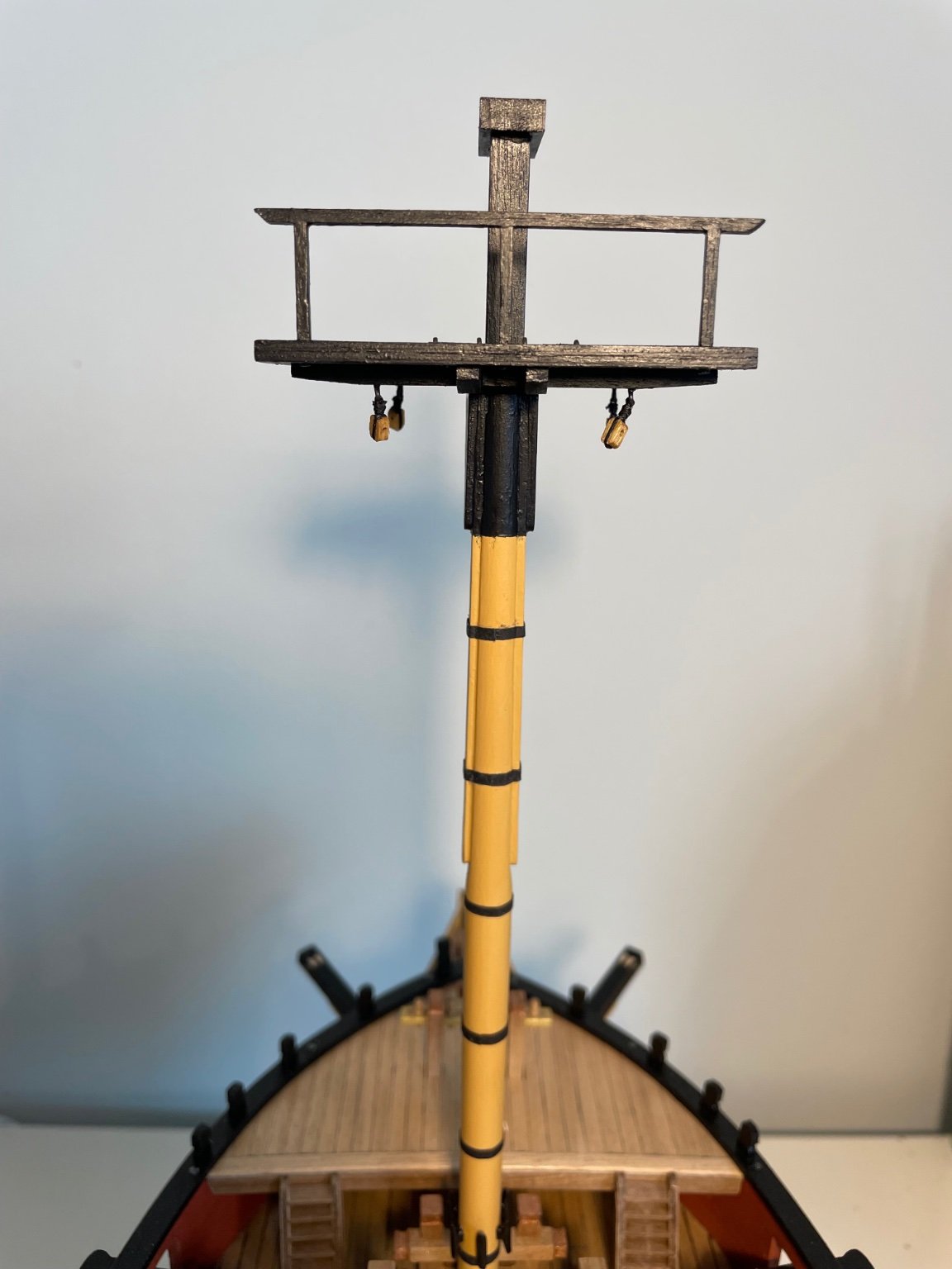
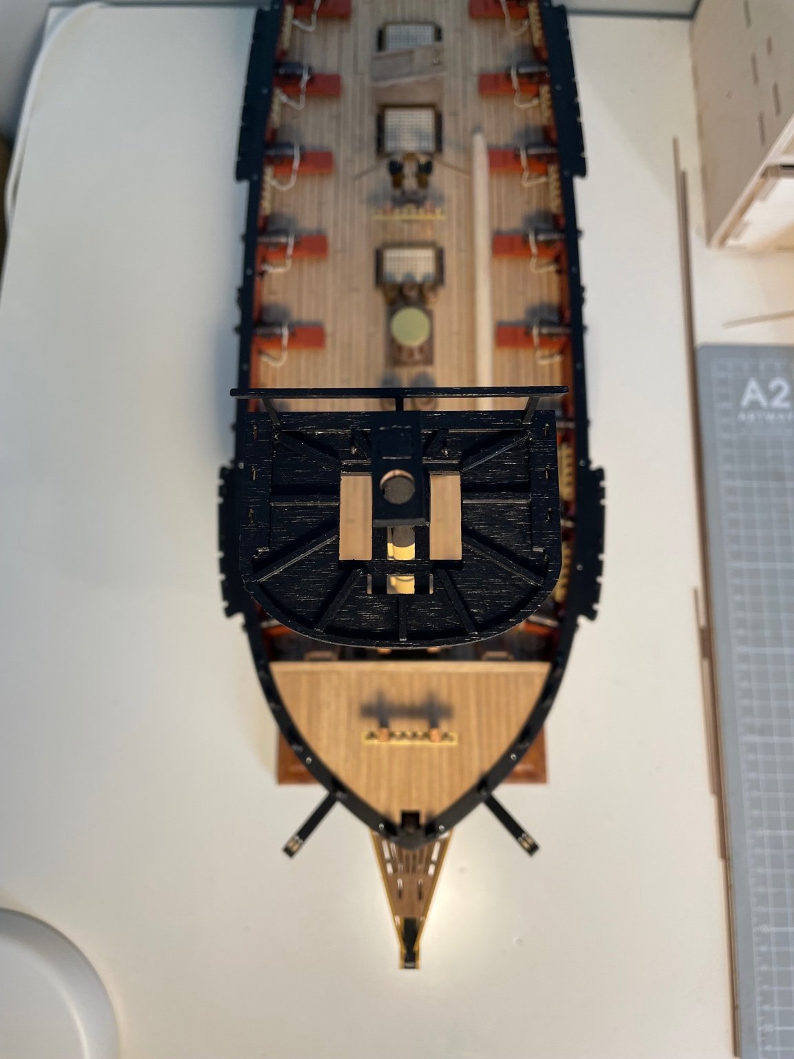
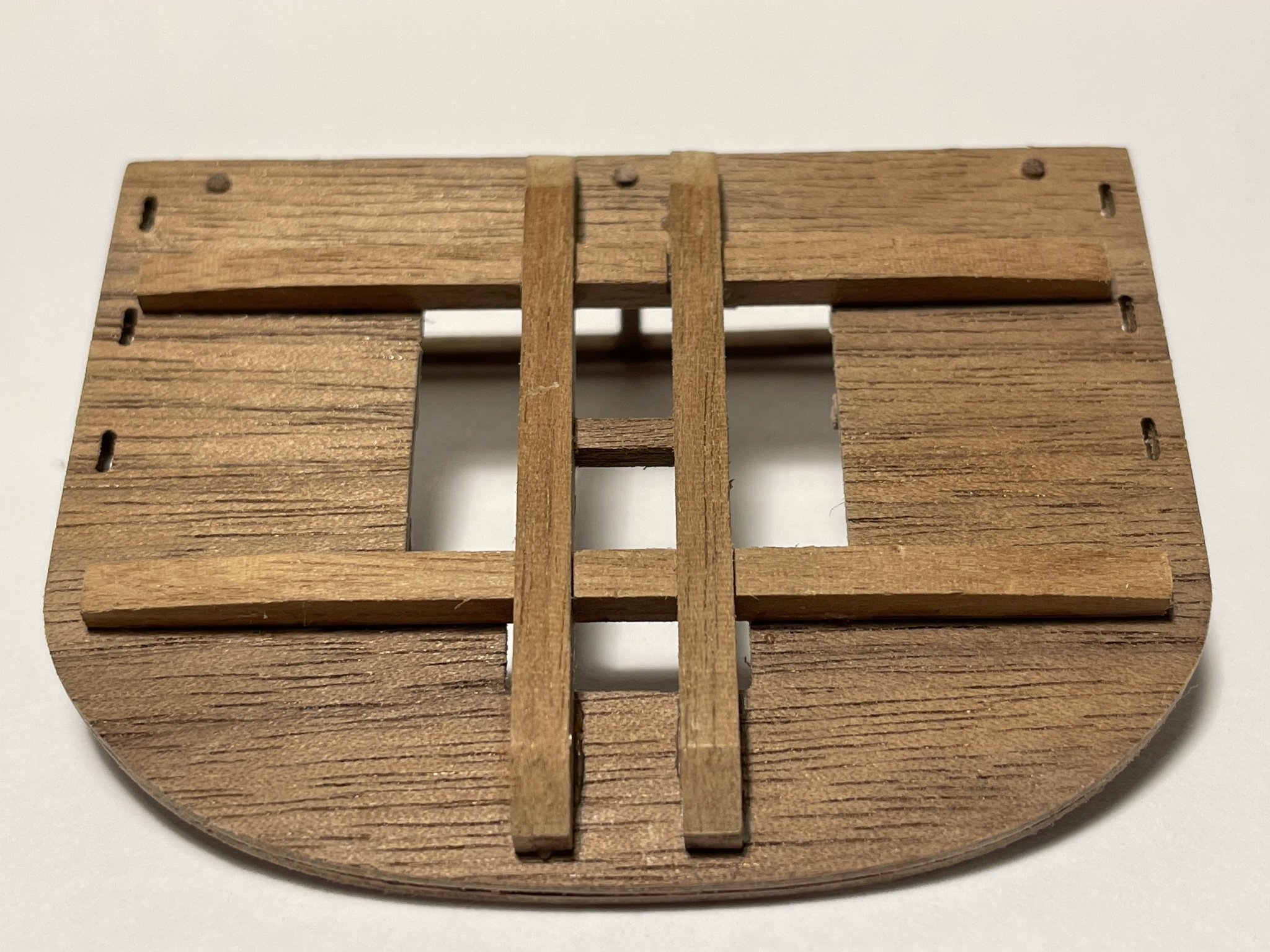
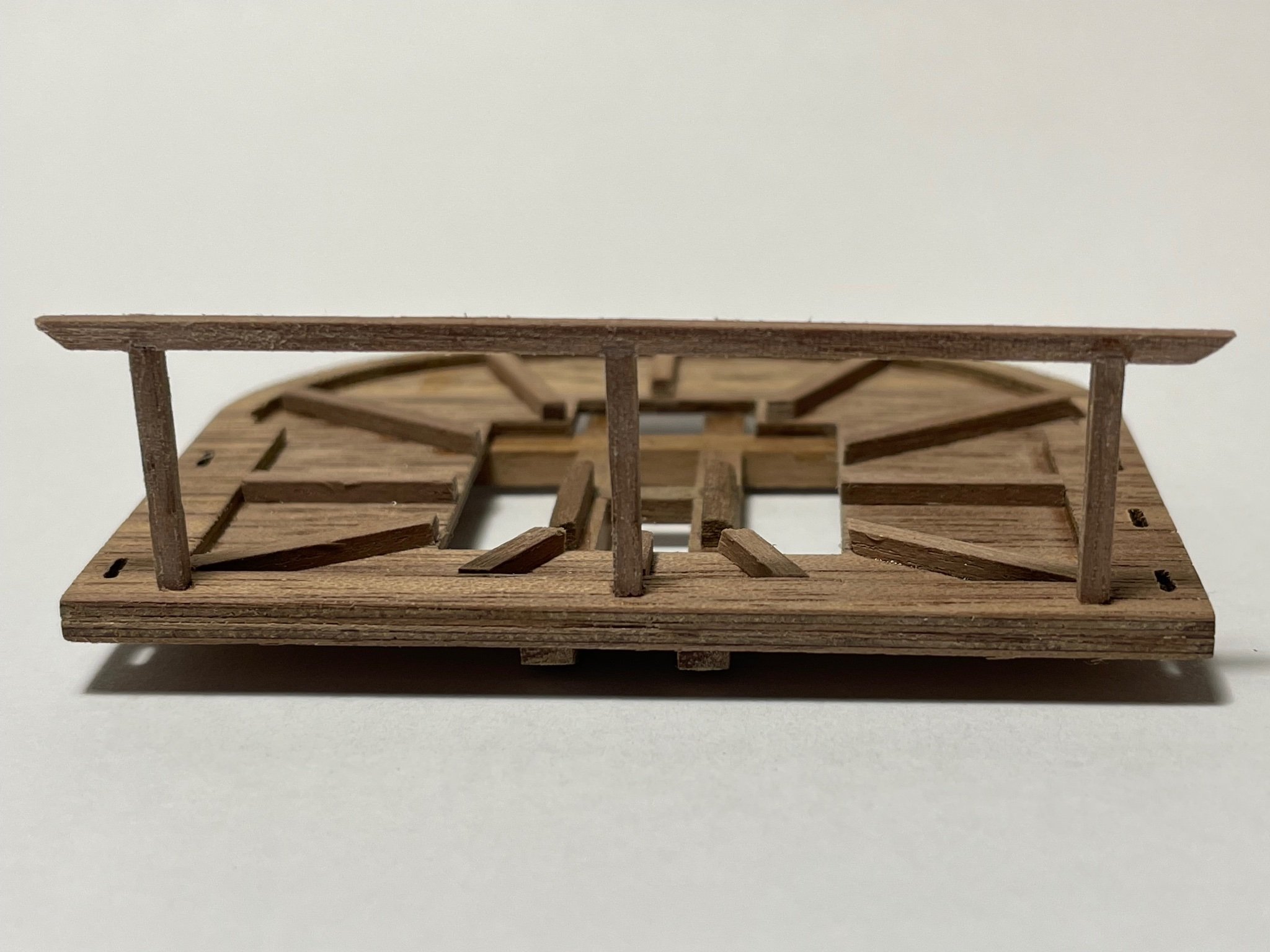
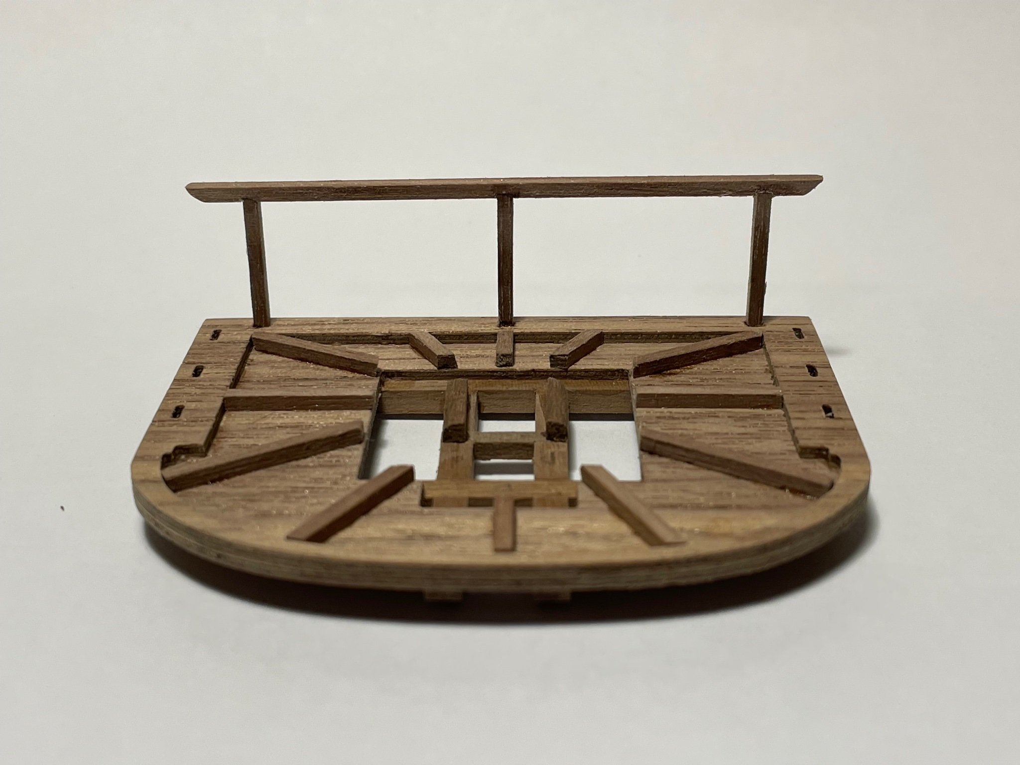
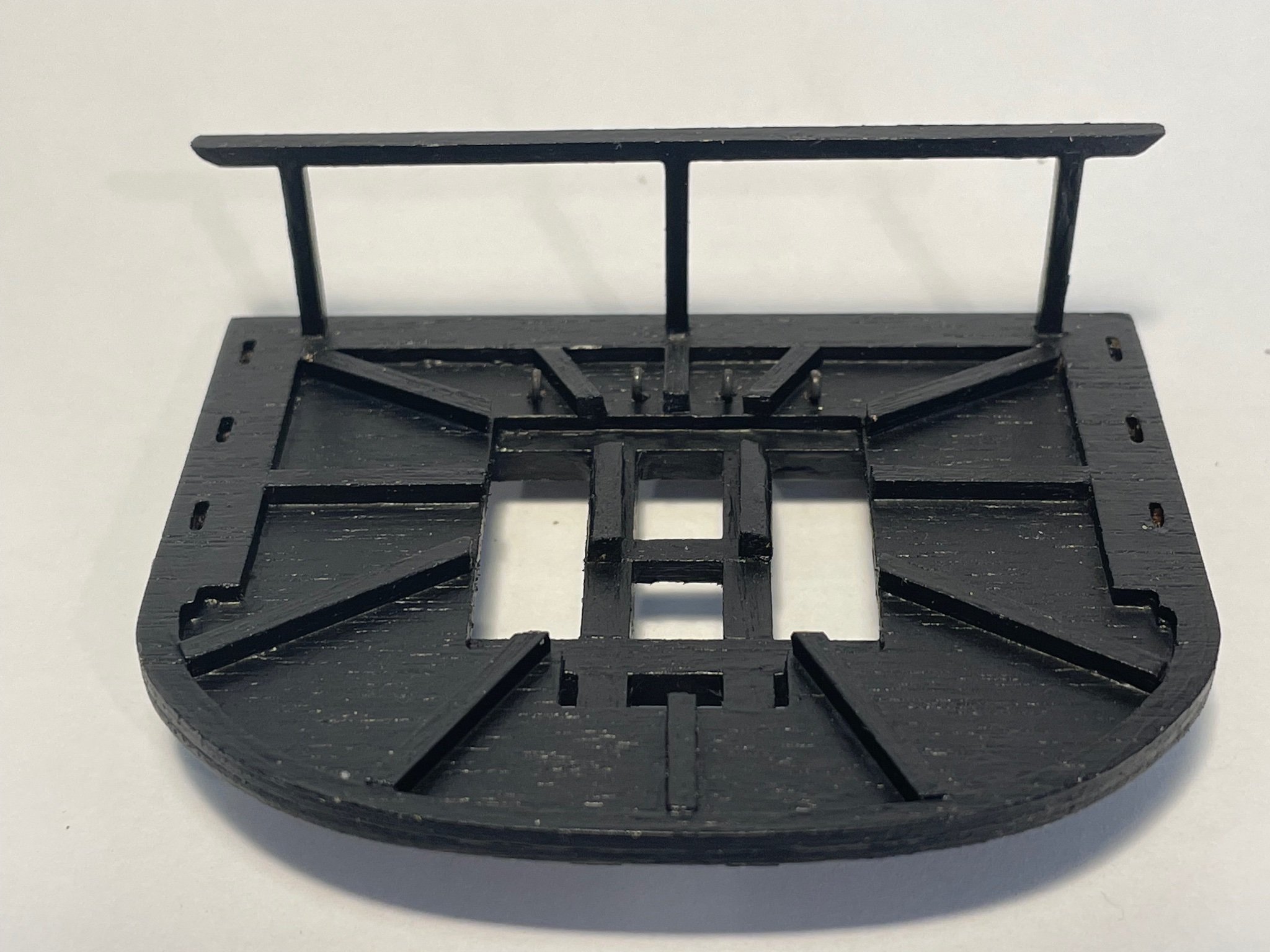
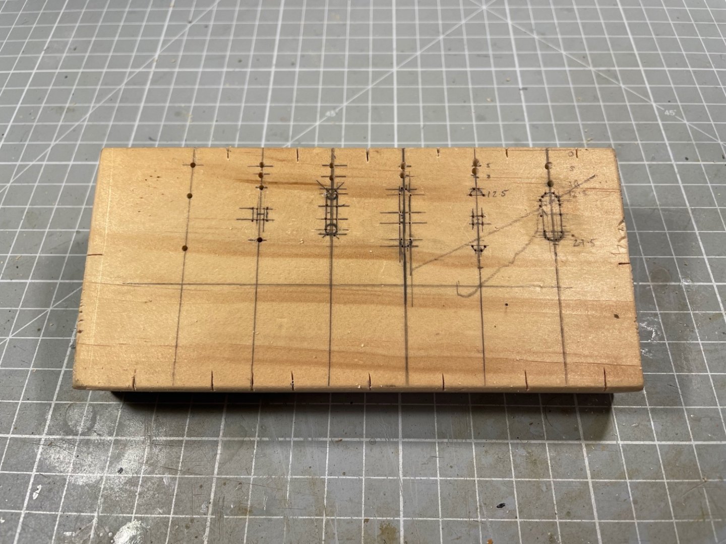
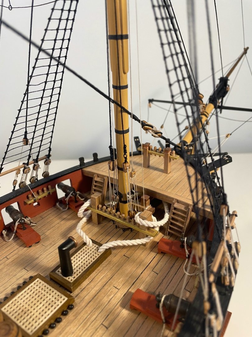
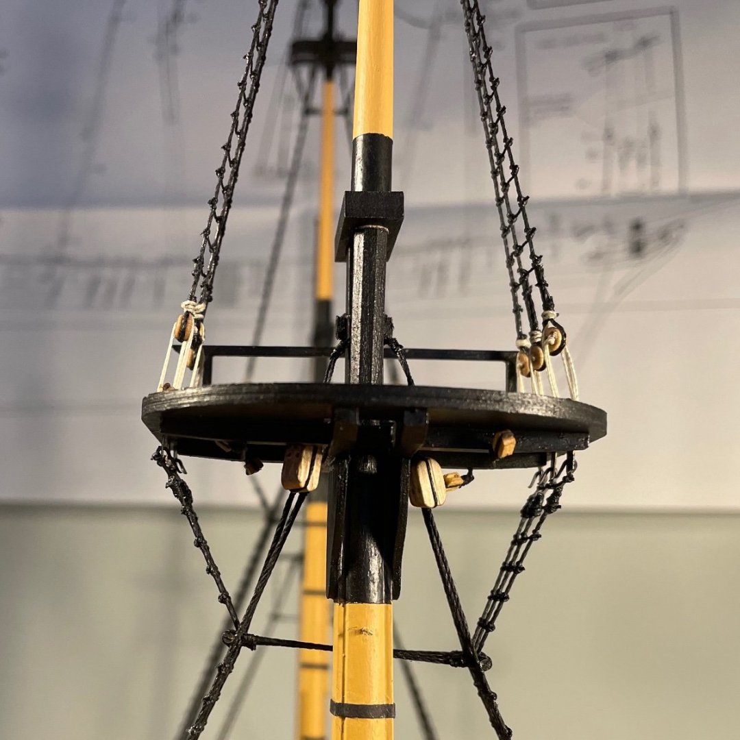
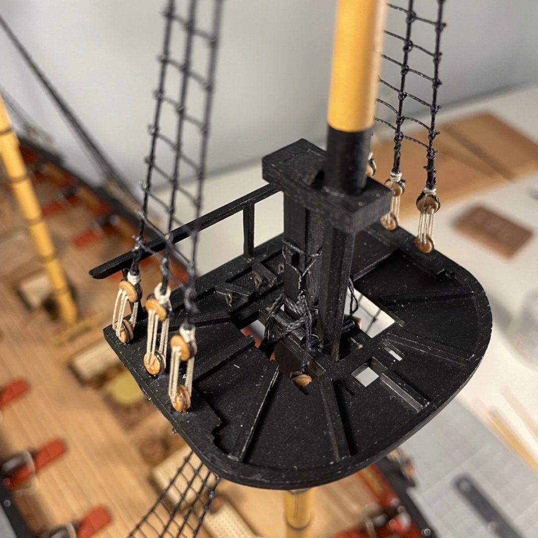
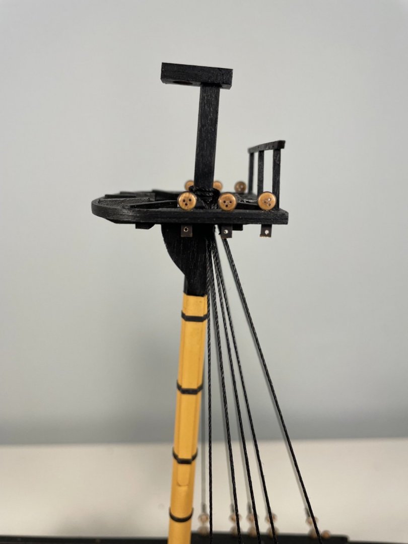
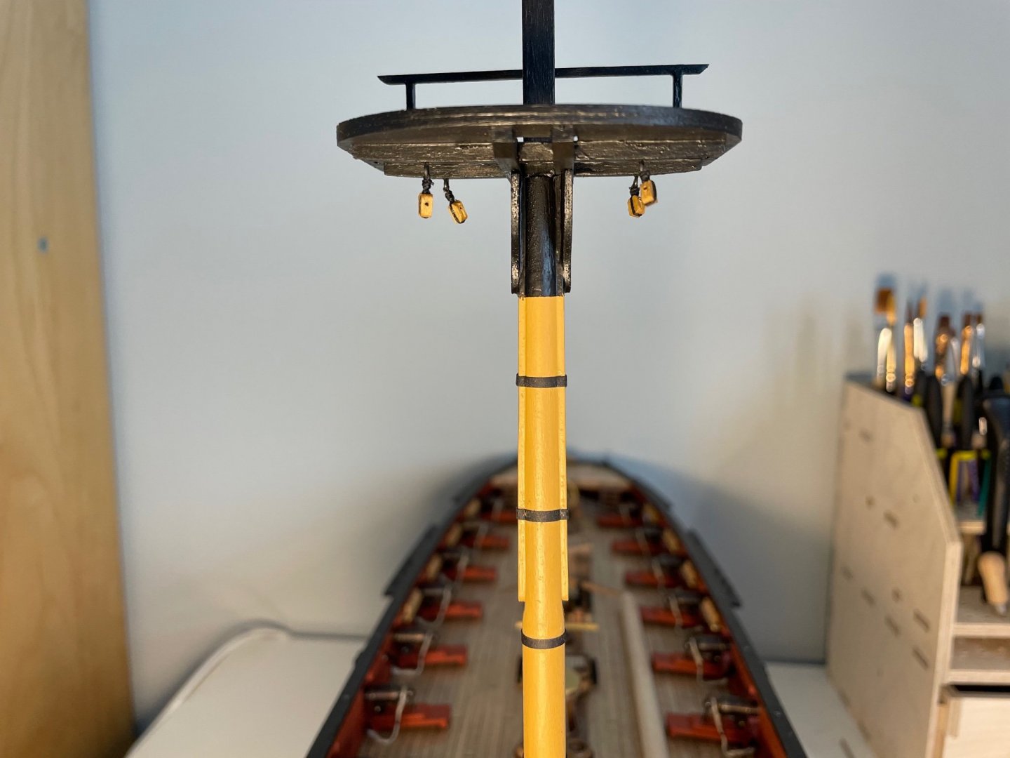
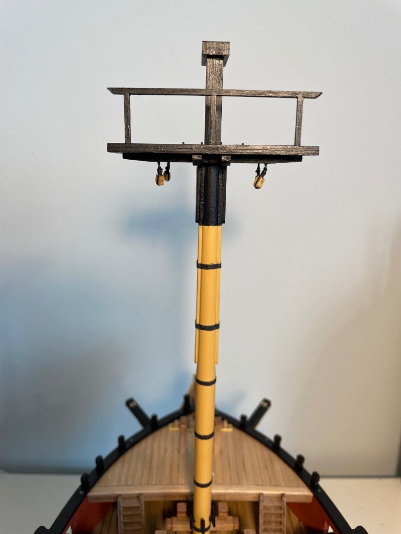
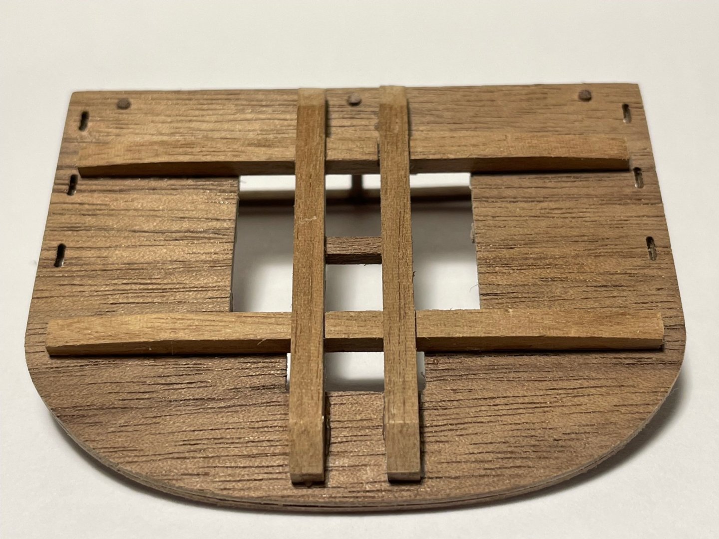
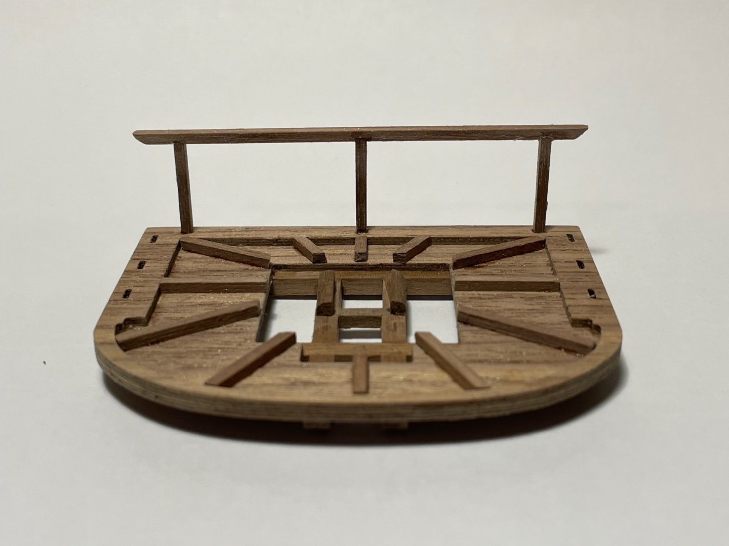
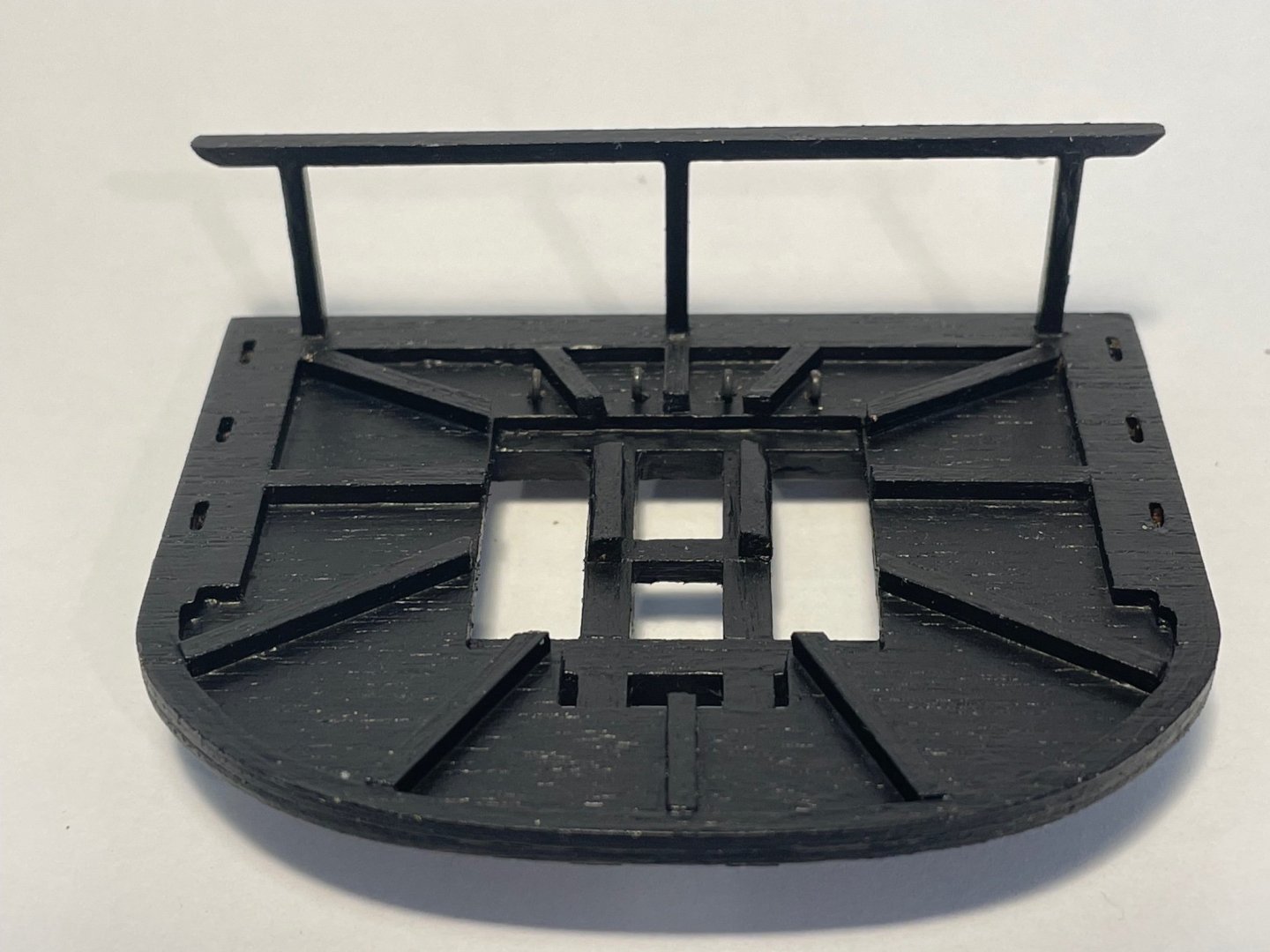
Fore Top Quite a lot of fun to build, but surprisingly labour intensive. The Trestle- and Cross-trees should slot together but the slots need to be machined out. Two pieces of original thought required. I laid out the battens at 30º intervals radially around the centre of the mast - I'm not sure what the real-life arrangement was. To erect the rail along the after-edge I cut the supports 3 mm over-length, and then turned the bottom 3 mm to a 1.5 mm diamter, having drilled 1.5 mm holes along the after-edge of the top (you can see the circular supports on the underside). The supports then slotted-in as round pegs into a round hole. The rail itself I then marked up and milled 0.3 mm deep slots to take the tops of the supports. In the photographs you can just see the rebates to take the supports. Once glued it seemed remarkably strong And here it is painted and with the ringbolts and blocks installed.

- 109 replies
-
- 2
-
-
- snake
- caldercraft
- (and 1 more)