DocBlake
-
Posts
1,811 -
Joined
-
Last visited
Content Type
Profiles
Forums
Gallery
Events
Everything posted by DocBlake
-
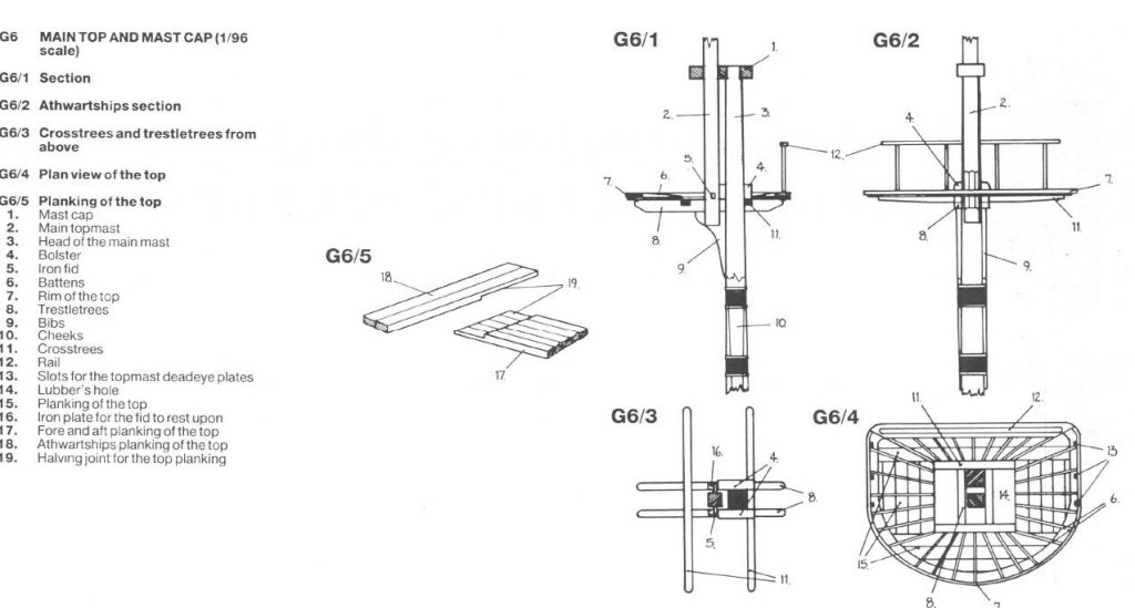
The mast head is the upper part of the lower mast segment. The doubling of the mast is the place where the top mast and the mast head join (they are "doubled") by way of the mast cap, the bolster and the fid. Here is a picture of the mast doubling:
- 1 reply
-
- 1
-

-
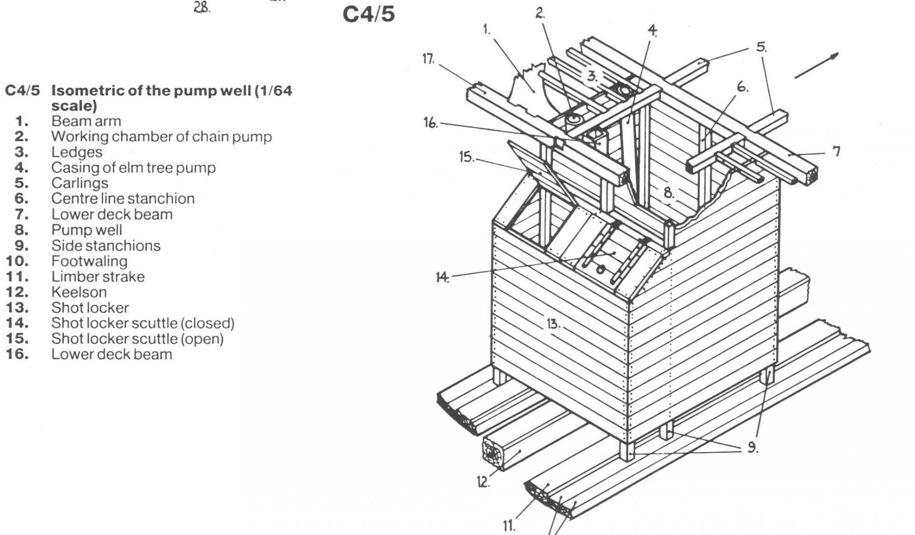
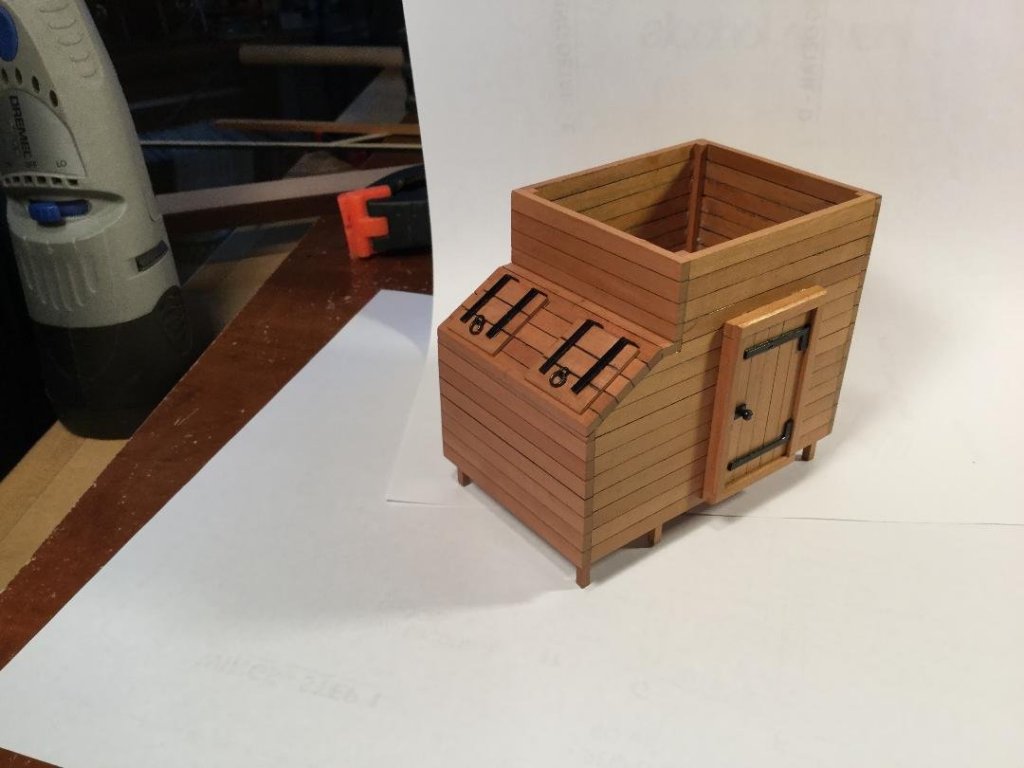
 Thanks, guys! The well and shot locker are modified from Mike's plans which were modified from Goodwin's drawing in his book. This build was not going to be 100% historically accurate!

- 164 replies
-
- 13
-
-
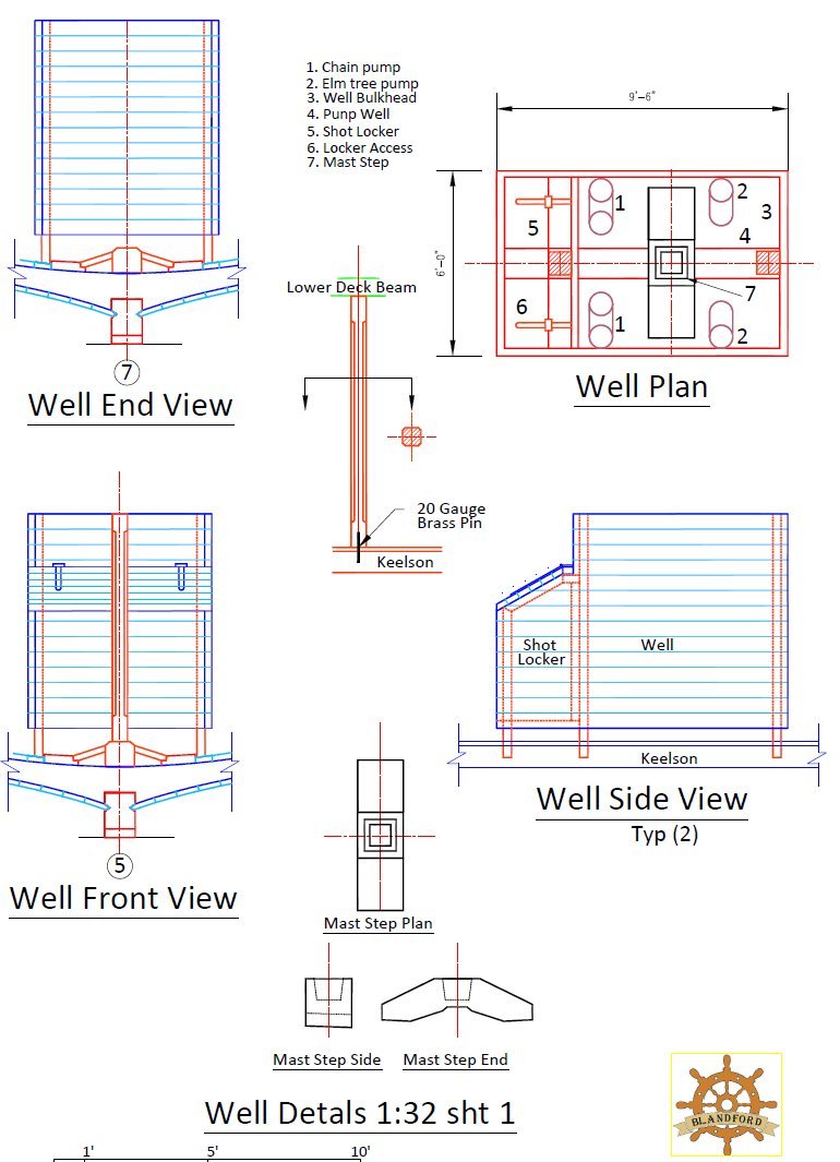
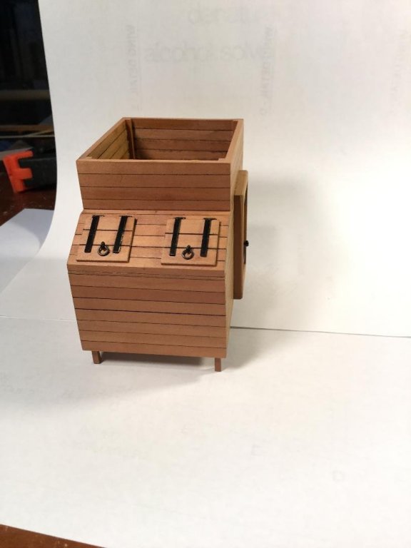
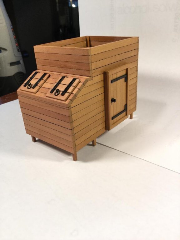
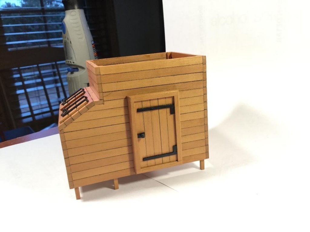
The well and shot locker have a close relationship to the two middle lower deck beams, so it's important to fit those beams first. The well just barely fits under the beams, and there are two pillars, one inside the well, and the second passing through the shot locker between the locker lids. Once the beams were fit, I started work on the well. The wood is swiss pear. I did opt for an access door which was framed in. The door measure 32" wide by 56" high in scale. I still need to add an additional coat of poly, then remove the sheen from the black hardware using Dull-Cote lacquer. The well and locker fit perfectly under the deck beams. I also need to make accommodation for the support column that passes through the shot locker between the scuttles and against the well wall.
- 164 replies
-
- 19
-
-
I have a Proxxon DB 250 wood lathe and would like to add 3 and 4 jaw chucks to my accessories to better turn round and square dowels. Suggestions as to decent supplier?
-
Great progress, David. Very nicely done!
- 145 replies
-
- 1
-
-
- model shipways
- charles w. morgan
- (and 1 more)
-
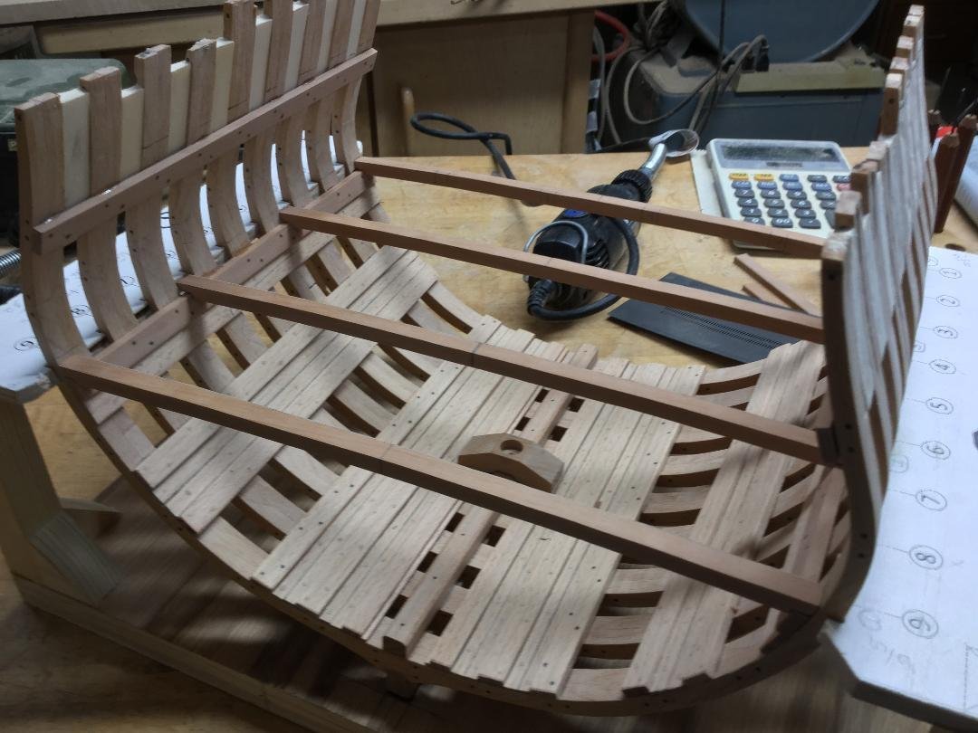
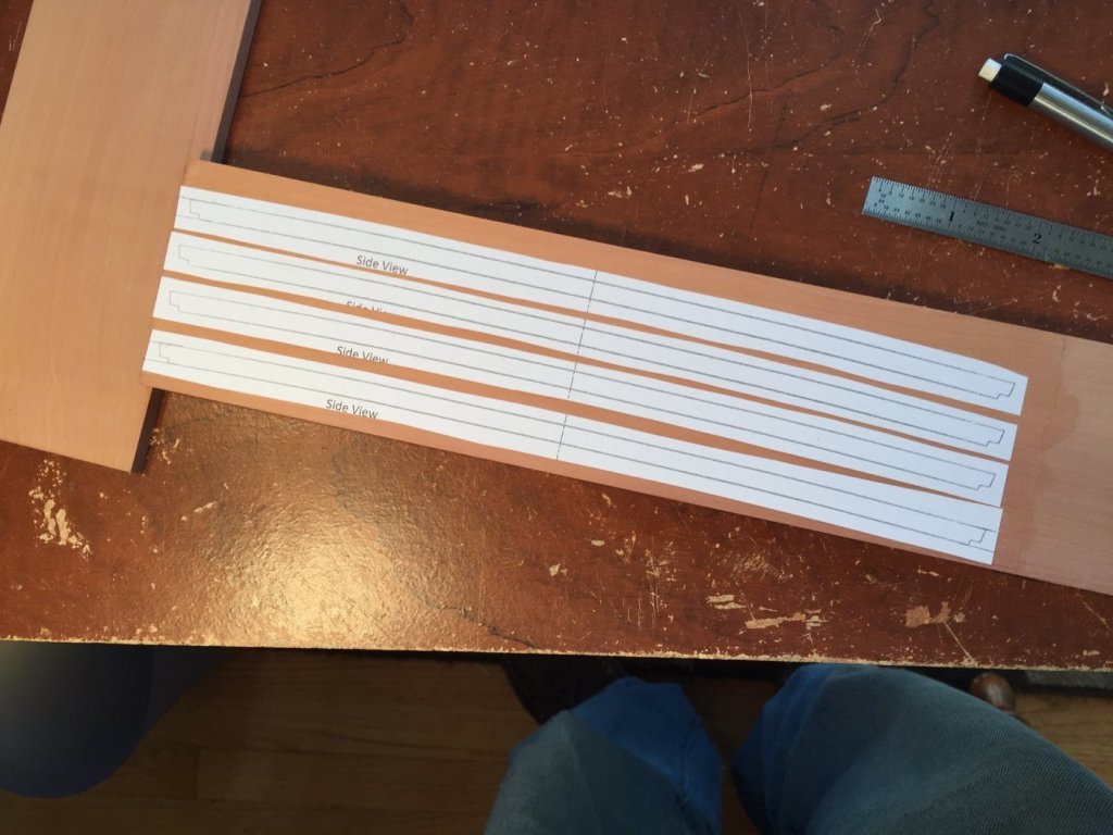
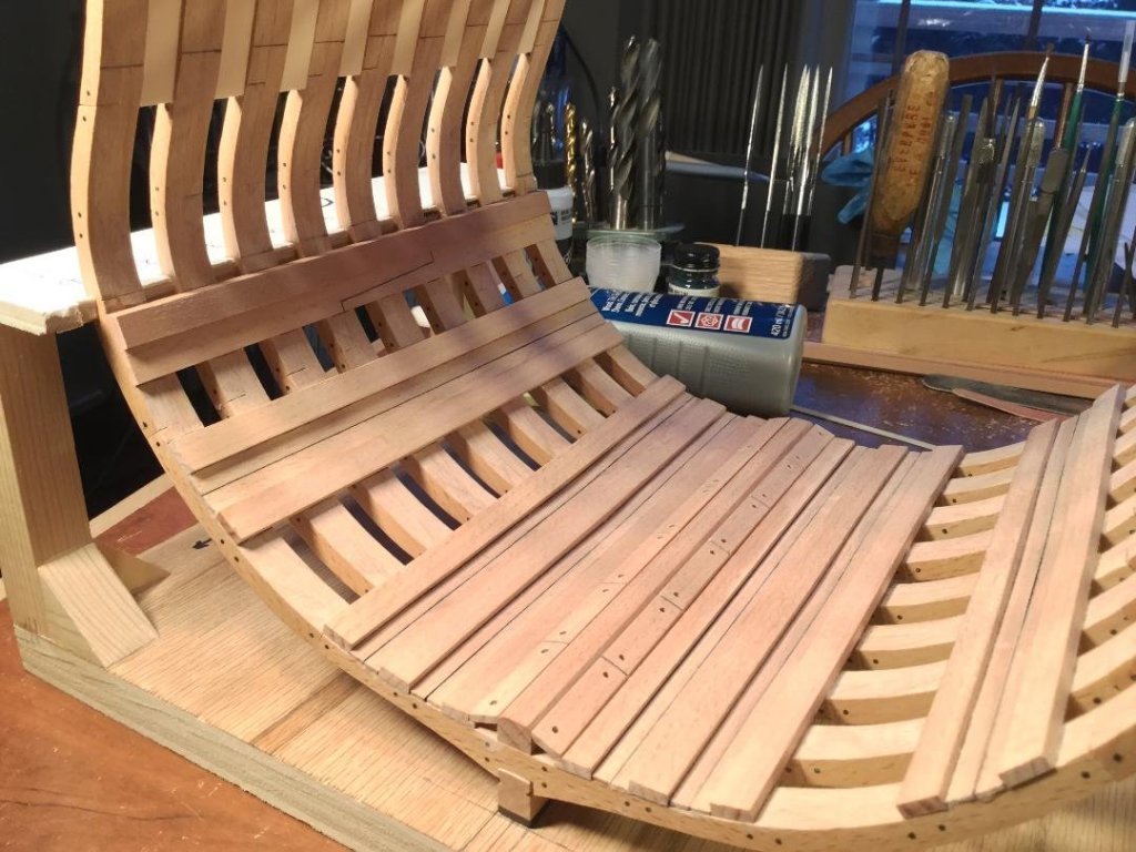
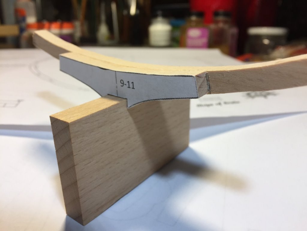
Thanks Elijah! Glad you looked in! As you can see in the above post, the beams have a rabbet on the ends that sits on the shelf that is the upper surface of the clamps. It's important to get the depth right and consistent on all 4 beams so the framing/decking sits flat, with no high spots or low spots. It's also critical that the beams fit between the clamps with no side-to-side play so that the centerline of each beam stays truly at the centerline. All the mortises for the carlings, ledges arm beams etc. are referenced off the centerlines of the beams. It took me well over 2 hours to custom fit the 4 lower deck beams! I think it will pay off during the remaining deck framing. I wanted to say that some might be tempted to use beams with no camber, creating a flat deck. If you have access to a scroll saw, by all means try cutting the camber on it. It was much easier than I expected, and it cleaned up quickly with sanding blocks. Just leave a "sliver" of white paper around the pattern to allow for the sanding. You can see a difference in the color of the model due to lighting. The photo below was taken in my basement shop, equipped for full sized woodworking and has all florescent lighting with halogen work lights in some places. Note the mast step in place. I also plan to leave off the limber boards inside the well to accommodate the pumps. Even though this detail won't be visible, I know it's there, and that was how it was on the real ship

- 164 replies
-
- 11
-
-
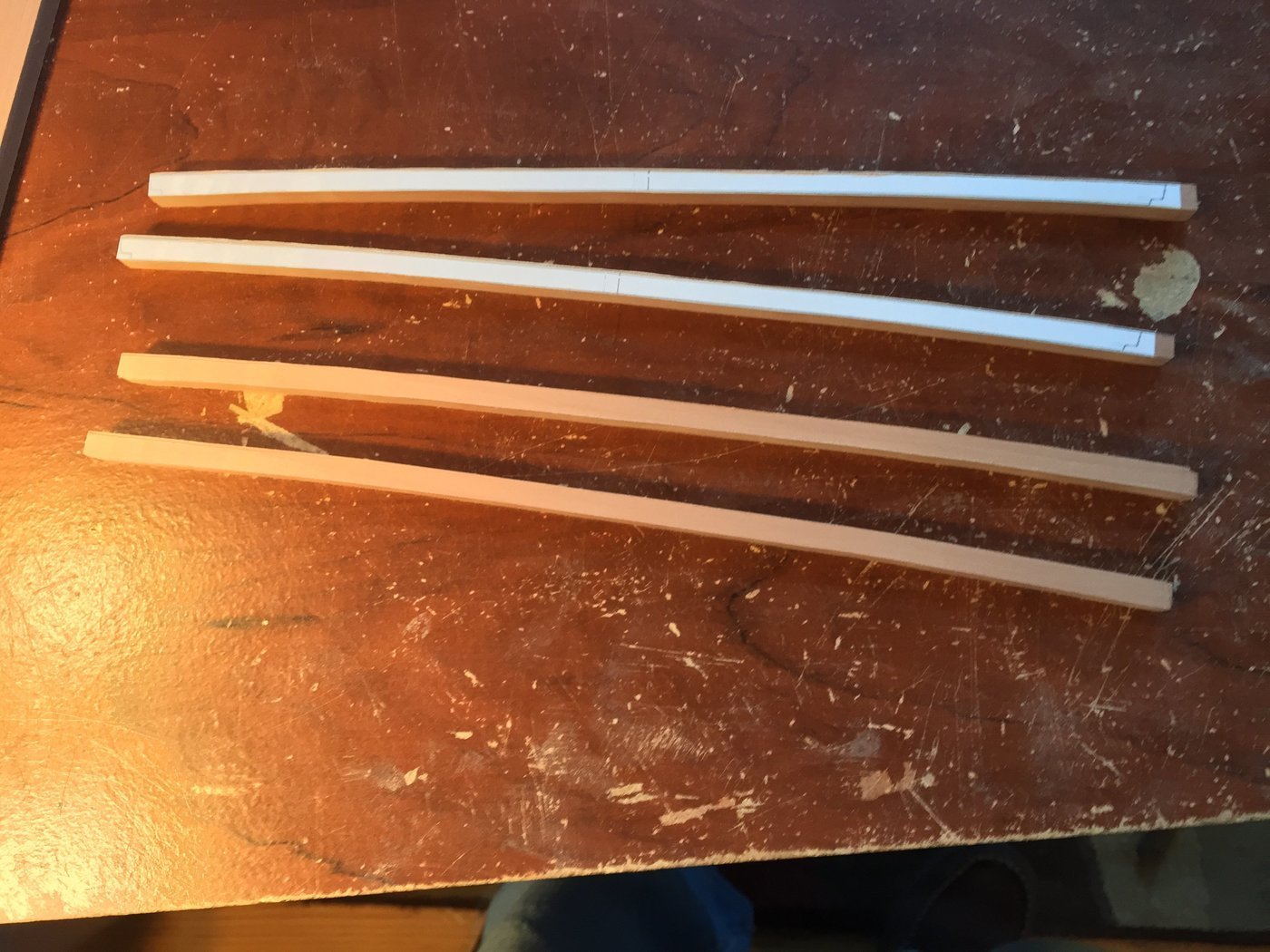
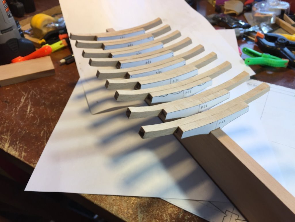
Thanks, guys! For some reason the decks on my build don’t narrow moving aft as much as the plans. I’ll have to resize the deck beams back there. As long as I keep the centerline consistent, and keep the notches for the carlings etc.in proper relationship to the centerline, I should be good! The lower deck beams are 9/32" wide and 3/16" thick. I laid them out on some 9/32" swiss pear stock and cut them out with the scroll saw. I left them a little long to fine-tune the fit. They cleaned up easily with sanding blocks. Time to get serious about deck framing!

- 164 replies
-
- 14
-
-
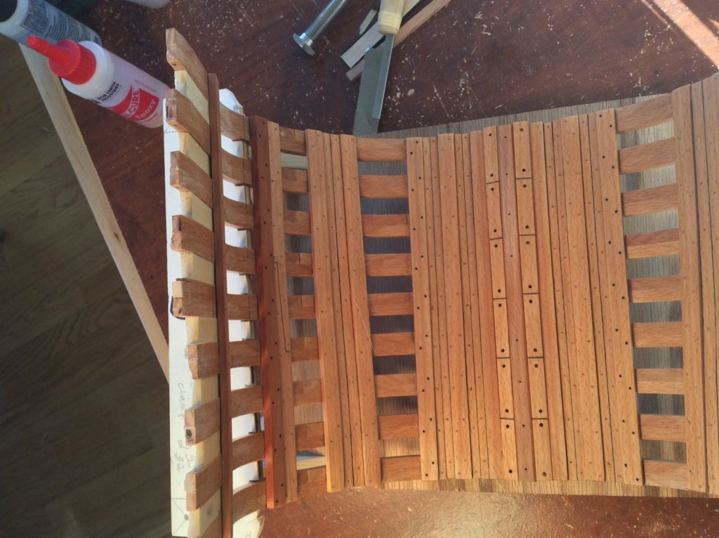
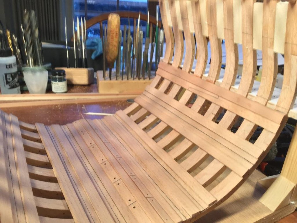
I decided to use black treenails simulating bolts to fasten the deck clamps and one strake on either side of the hold floor. All the other strakes and footwaling treenails are birch toothpicks. I don't think the effect is over done at all. The deck clamps are swiss pear, as will be the deck framing. The lighting makes the beech look reddish.

- 164 replies
-
- 15
-
-

-
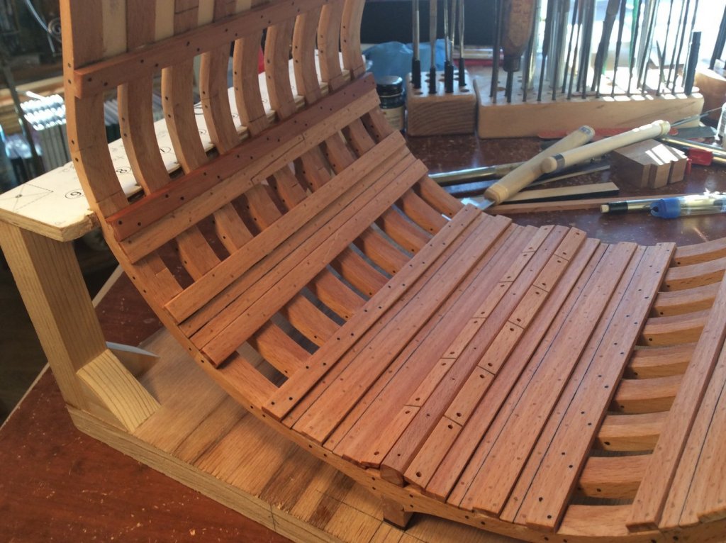
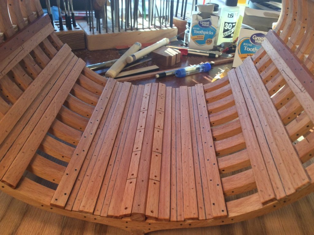
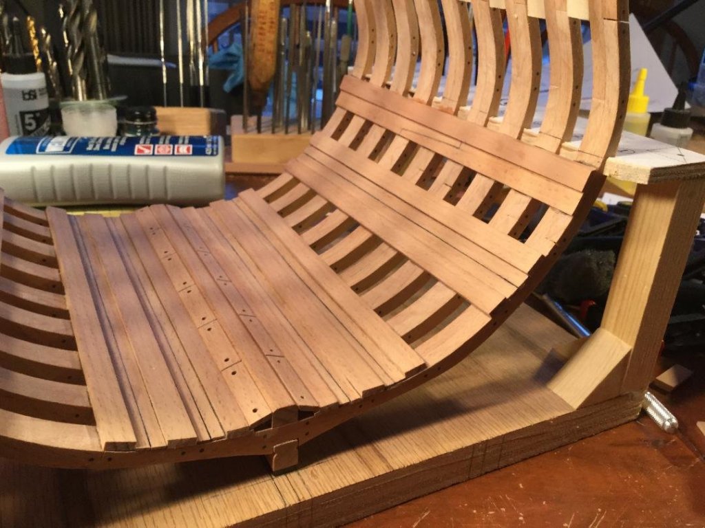
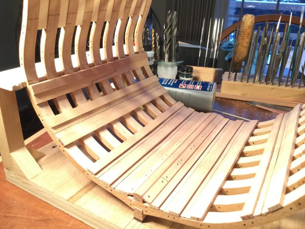
I finally finished the strakes and footwaling in the hold, and mounted the lower deck clamps. The deck clamps and lower deck framing will be swiss pear. I also added a strake below the clamps with a simulated scarf joint . My plan is to fasten done the keelson with some scale model railroad spikes to simulate bolts. I'd like to use dyed black toothpicks and do the same to the strakes and footwaling, but I'm afraid the effect might be "too much" and look like a case of measles! We'll see!
- 164 replies
-
- 15
-
-
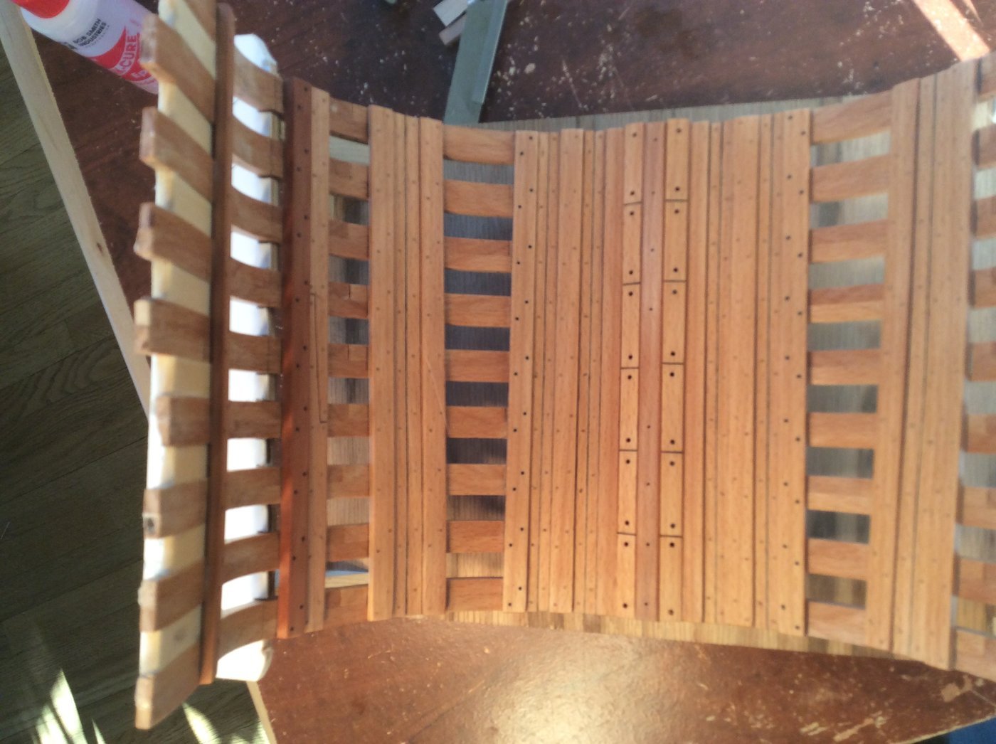
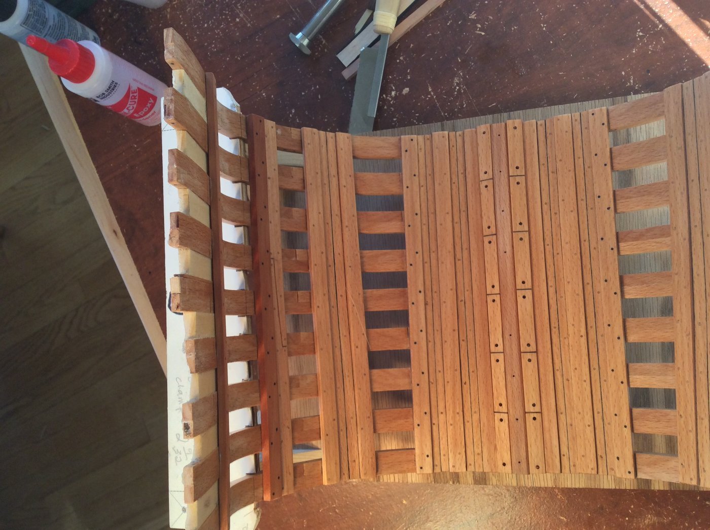
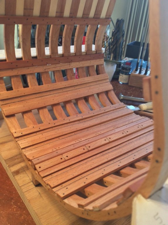
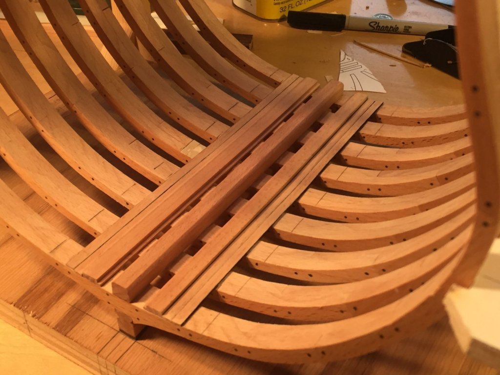
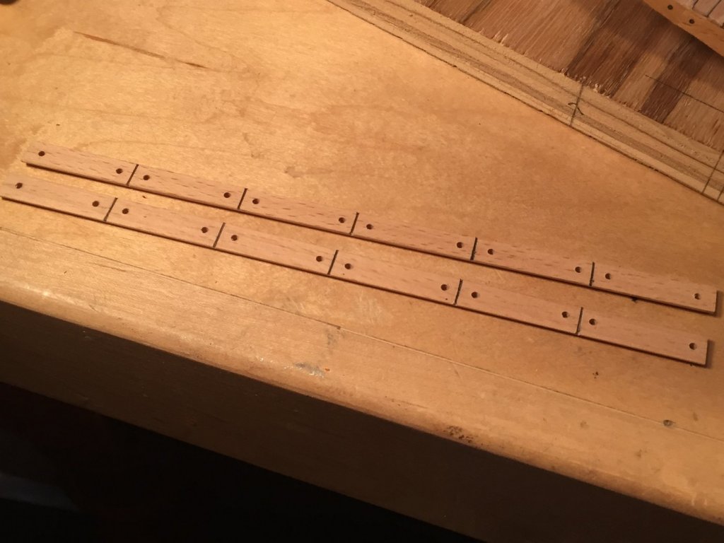
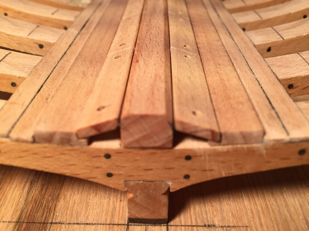
Thanks, Hamilton, and thanks to everyone for the "likes"! After careful sanding and fitting, I glued the keelson to the frame floors using epoxy. I'll add some reinforcing bolts a little later. I cut the rabbet for the limber boards into the first strake using my Byrnes saw. The limber boards are one continuous board, with separations simulated with a X-Acto blade, a narrow needle file and pencil marks. I drilled 5/64" holes (2-1/2" in scale) for the finger holes. I then started laying the floorwaling. The last photo is a detail of the limber board-keelson anatomy. None of the wood has poly yet. All the hold planking is European beech.

- 164 replies
-
- 20
-
-
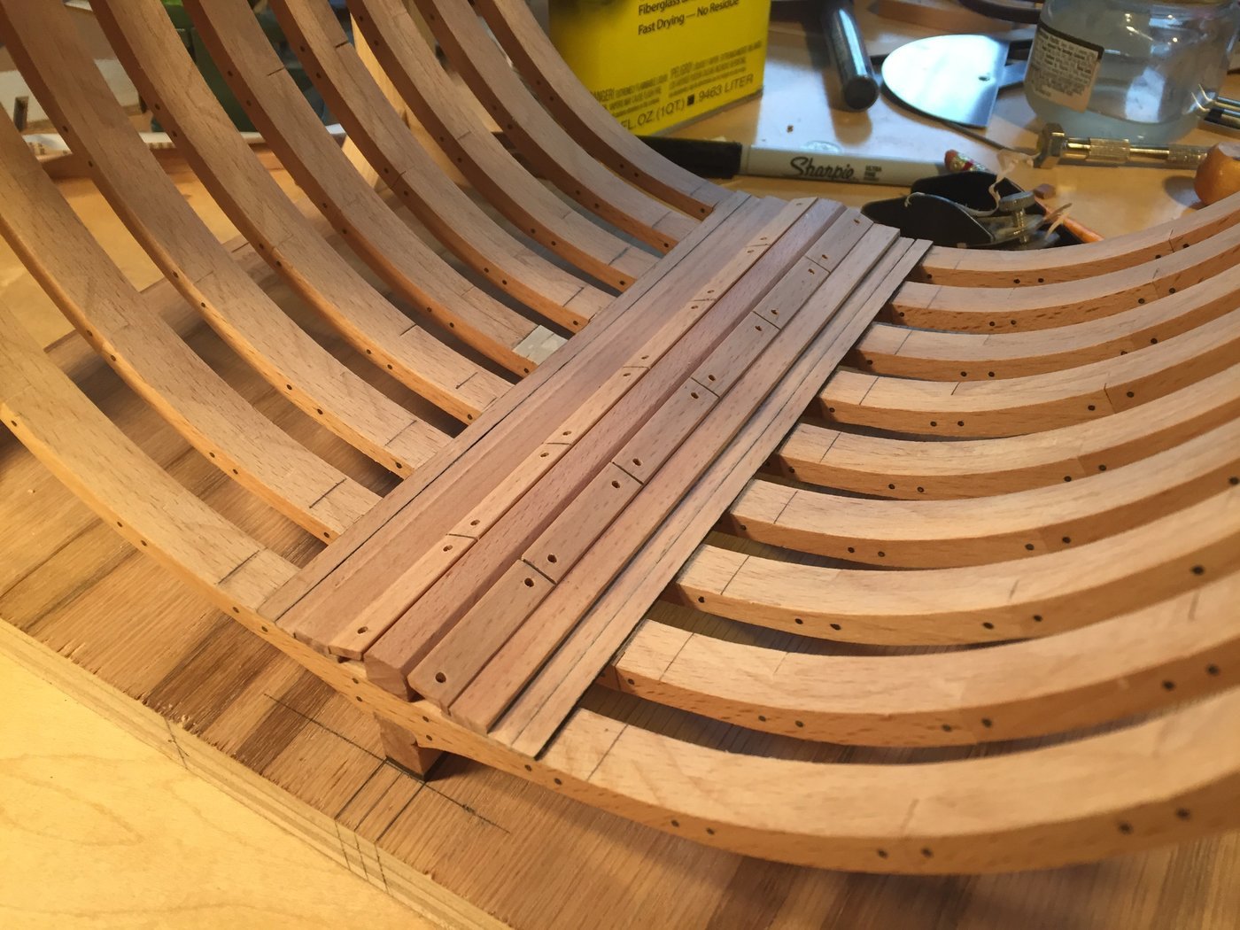
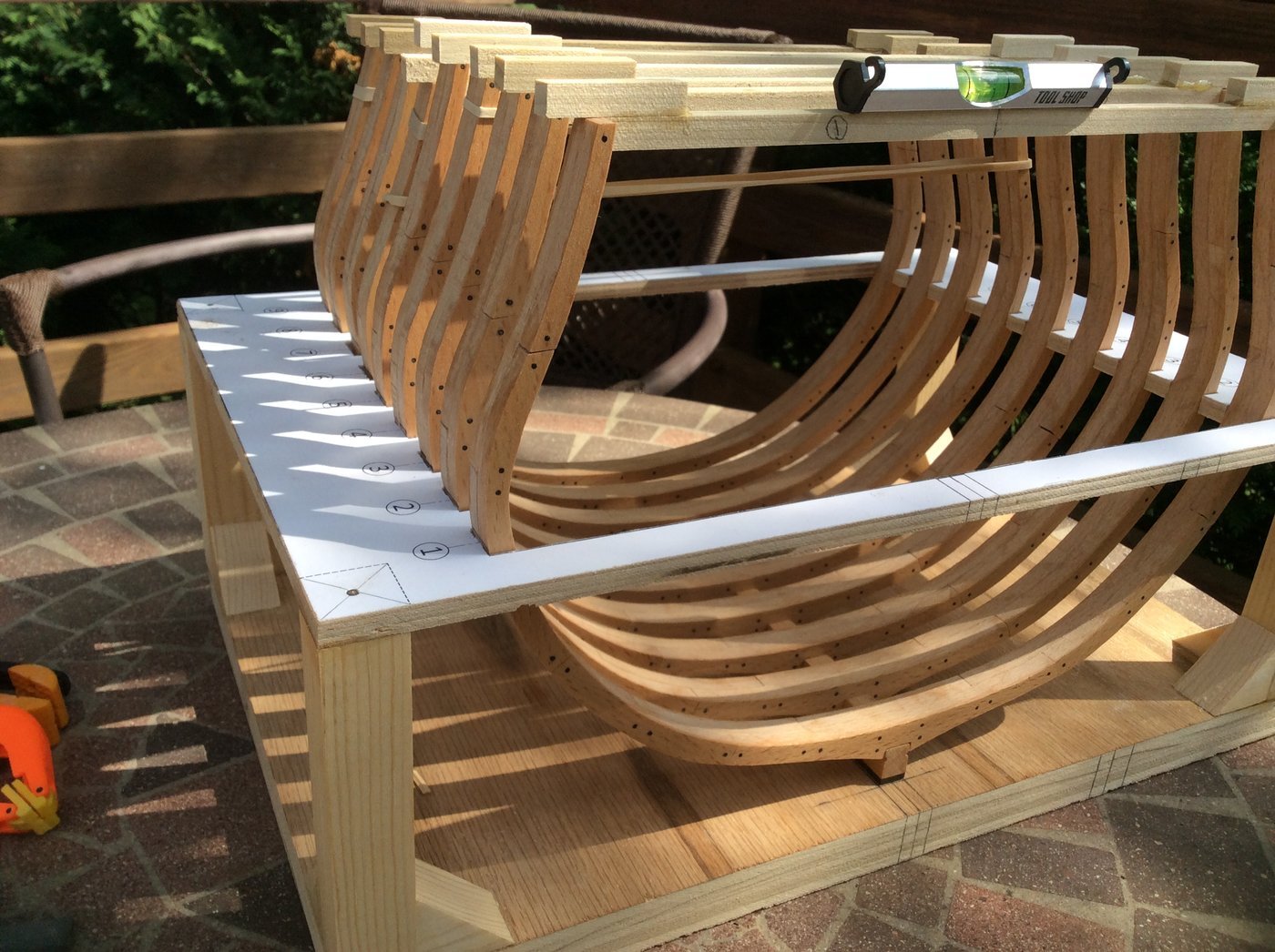
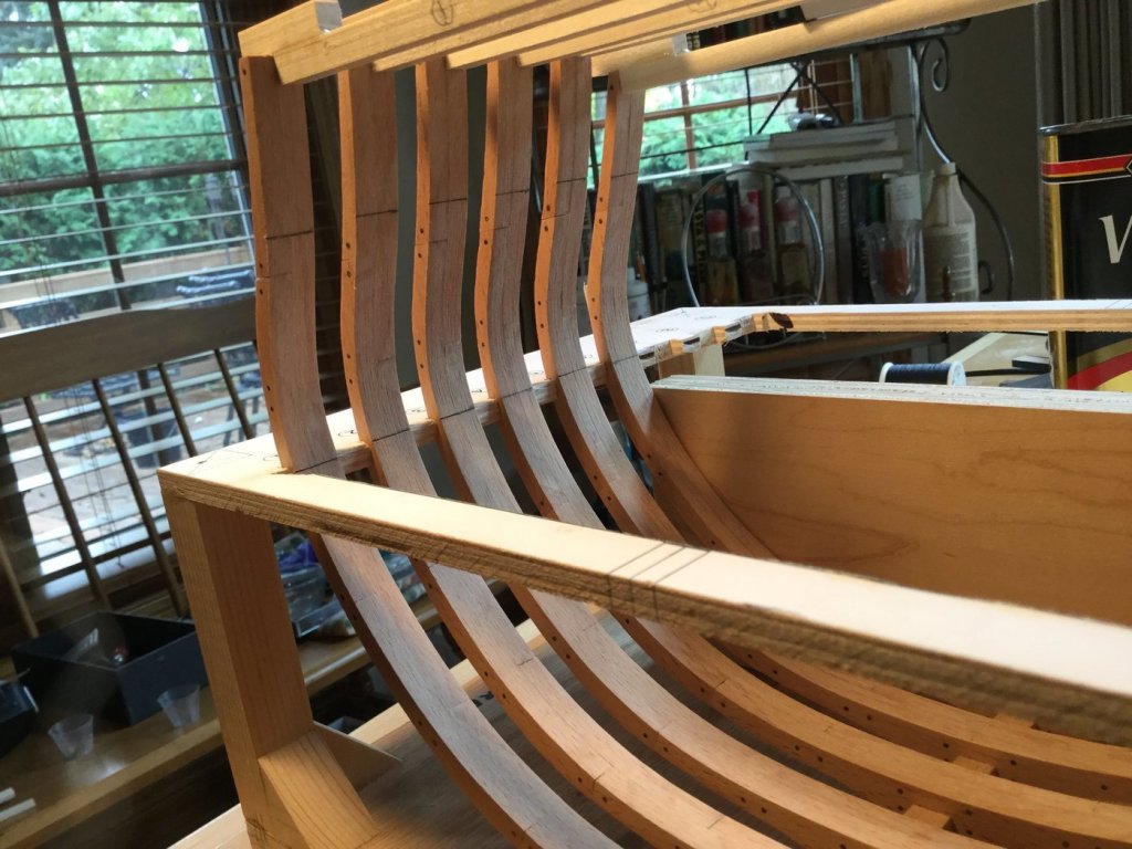
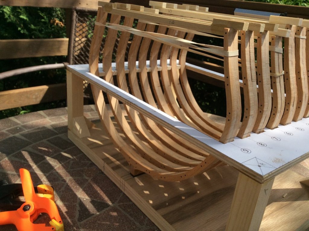
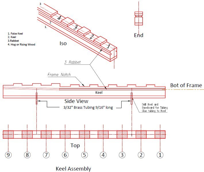
I finished the keel and used brass tubing, glued to holes in the keel to fit into holes drilled in the build board to mount the keel. It's removable. I sanded the inboard side of all the frames with my spindle sander and I marked the location of both the upper and lower deck clamps on each frame from the plans. Then I scored each line with an X-Acto knife so the location marks would remain, even after final sanding. I carefully plumbed each frame and centered them on the keel using a squaring jig and line level. the first 5 frames are virtually identical and are glued in place. Frames 6-9 taper inward moving aft and begin rising on the keel also. That's next.
- 164 replies
-
- 14
-
-
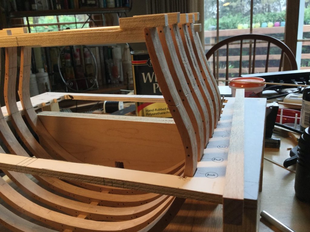
I added brass tubing to the keel bottom and drilled holes in the build jig to keep the keel stationary. The Frames are dry fitted to the keel and the jig. Very small adjustments are being made with files and shimming so each frame is square and plumb. Once that's complete I'll glue and dowel the frames in place.

- 164 replies
-
- 15
-
-
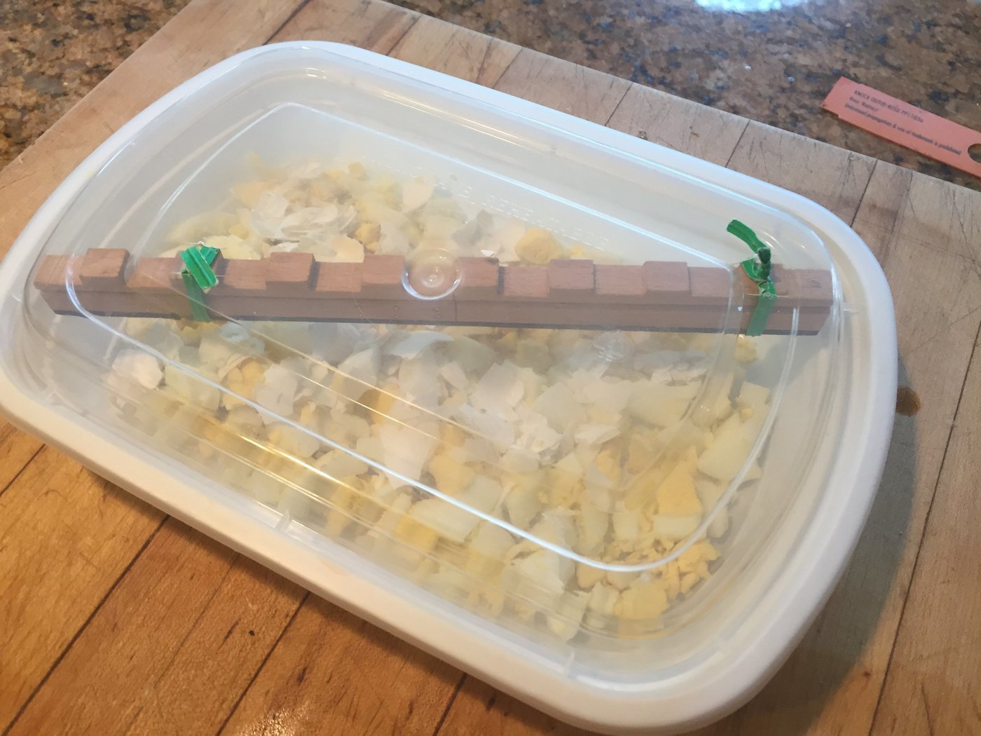
Hamilton: The idea was to keep the framing relatively simple, so a novice builder would be comfortable. I have no earthly idea why I chose copper for the bolts! David: The Beech is really nice to work with! After I realized my mistake in using copper for the keel scarf, I figured out a strange way to blacken the copper. Normally to simulate black bolts I would cut of the ends of toothpicks and let them sit in a bath of Solar-Lux Jet Black wood dye. The dye penetrates the full thickness of the toothpick so no white core. Just put the tip in some CA glue and push them into place. Clip and sand. This is kind of crazy but let me explain what I did to "blacken" the copper bolts in the keel. I first tried "painting" the exposed copper with Jax Black and Brass Black. The black residue that formed bled into the surrounding wood and made a mess. I sanded back to bare wood and metal and tried again. I tried painting the copper flat black, but the results were not uniformly round, and the paint looked terrible. Sanded to bare wood and copper again. The I saw something on the internet! Hard boil, cool and peel 2 eggs. Chop up the eggs and break up the shells and layer them on the bottom of a plastic container with a tight fitting top. Secure the keel to the top with bread bag ties so the part isn't sitting on the eggs. Wait over night. You can see the results in the photo. I did put a coat of poly over the blackening so that I don't damage it or rub it off somehow. The bolts still look like metal - but used and oxidized metal! It's the sulfur in the eggs!


- 164 replies
-
- 18
-
-
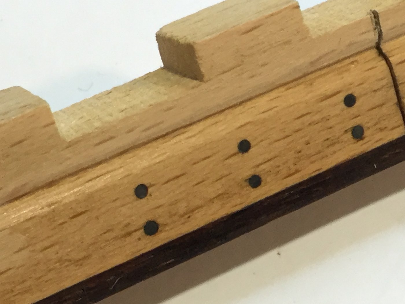
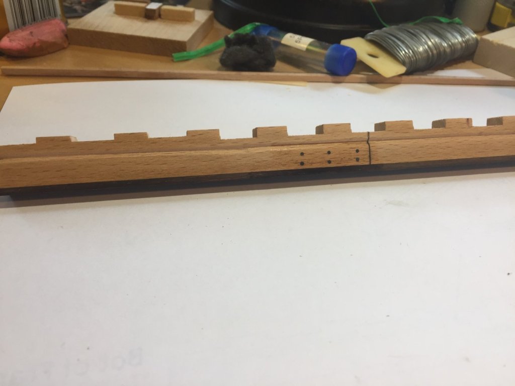
Thanks, G.L.! I was looking at the drawings of the HMS Blandford in the AOTS book. In the section represented by this build, there is a vertical scarf joint in the keel located right at the step of the main mast. It extends between frames 4 and 5. I think it would add interest to simulate that scarf joint and treenail both sides with 6 scale treenails. There are scarfs in the keelson at both ends of the model section, but since they end up as partial in this cross section, I think they are best ignored because they may look weird. I've enclosed a photo of the area in question with the scarf identified. I simulated scarph in the keel as shown in the AOTS drawings and used 18 gauge copper wire to simulate the bolts. You can see how much the beech resembles oak. Next up is blackening the copper. I'm trying a new method... hope it works!

- 164 replies
-
- 14
-
-
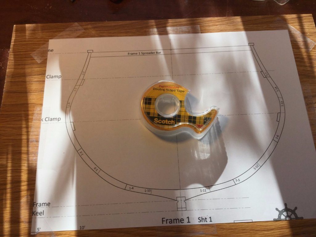
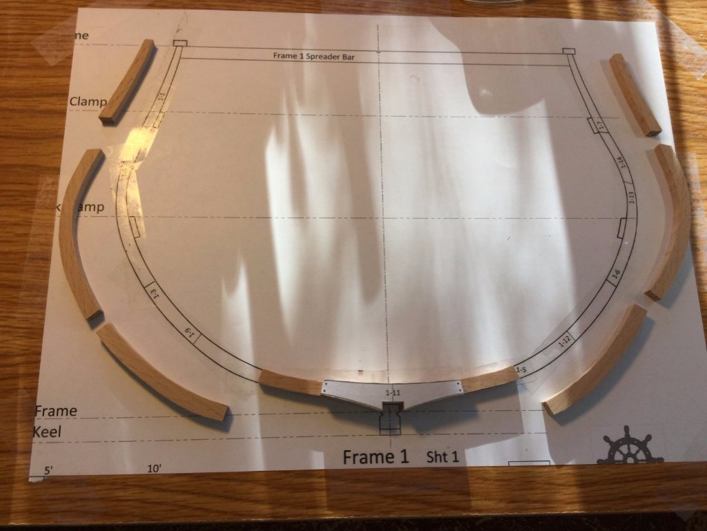
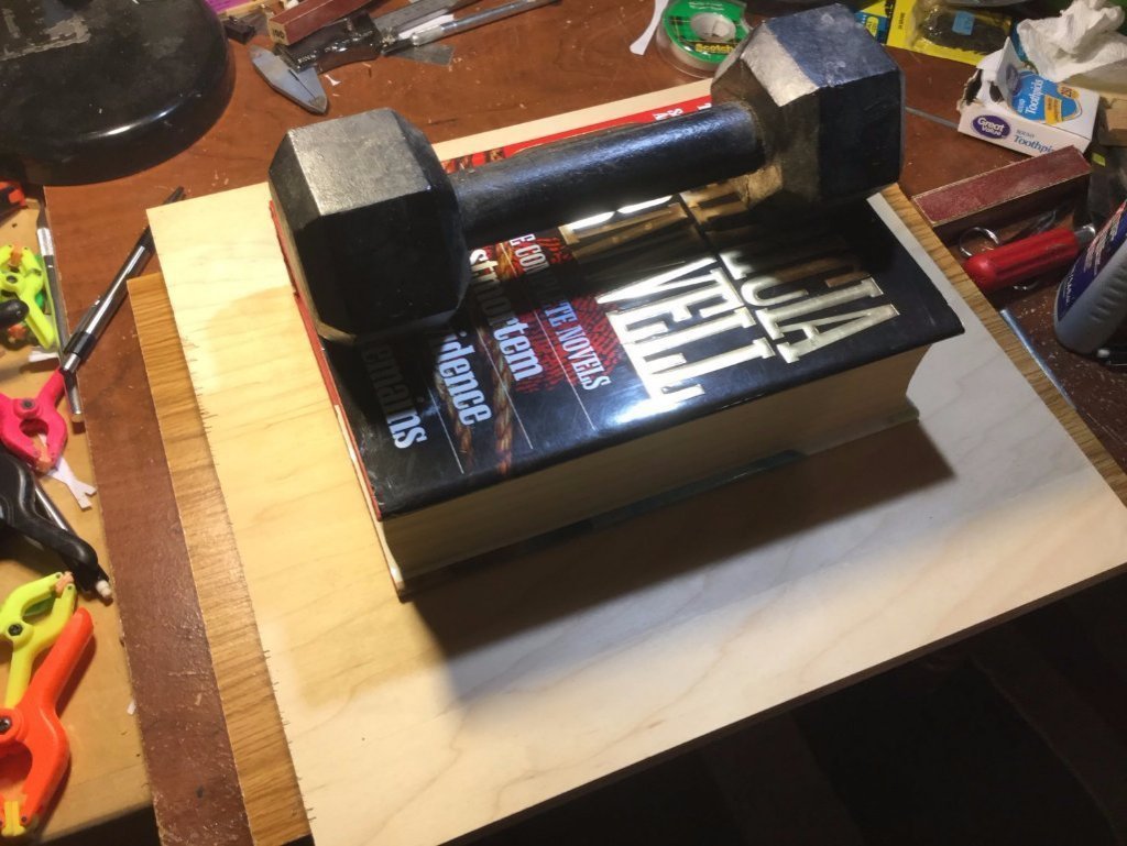
This is my method for glueing up the frames: I use Weldbond - it's easy to dissolve with isopropyl (rubbing) alcohol and easy to scrape off the wood with an X-Acto blade so it won't block any stain penetration. I don't use a sheet of glass, but rather tape the frame plan to a flat surface. A piece of melamine shelving works great. Once in place, I lay down Scotch double-sided tape over the frame outline. The first layer of the framing is laid down congruent with the plans and the tape holds each piece in place. I put a small drop of glue on the abutting surfaces of the first layer. When that is done, the second layer of the framing is glued to the top of the first layer with glue at all the butt joints also. I place a piece of plywood on the glued up frame and weight it down. The frames can come out in about an hour, but I wait overnight to remove the futtock templates and do any sanding.
- 164 replies
-
- 19
-
-
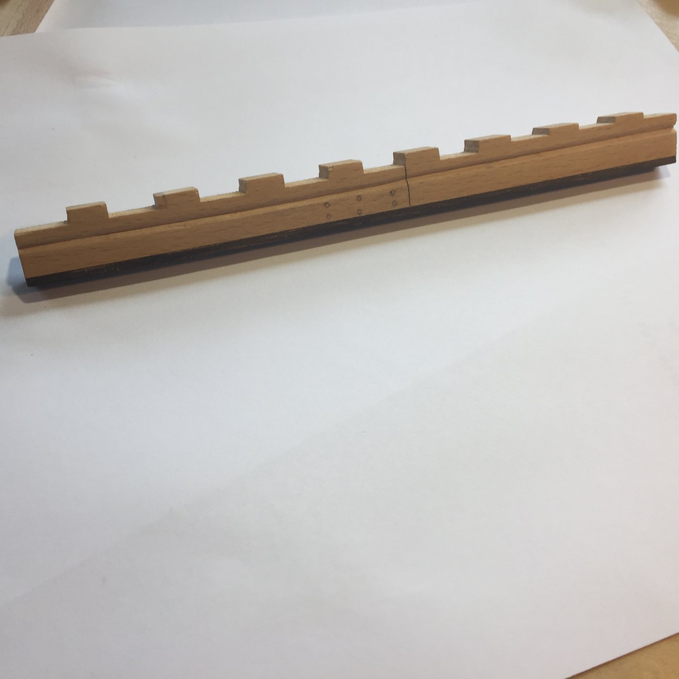
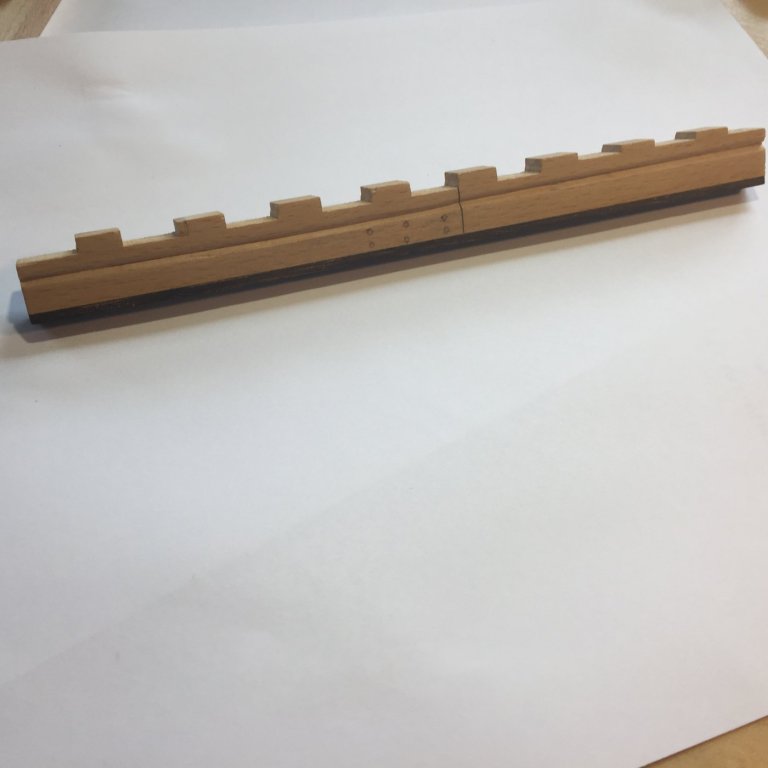
Hi Hamilton! The idea was to keep things simple. The keel was designed so that the aft-most frames (7, 8 and 9) sat higher on the keel than the first six. When the rabbet was cut, I just cut it to simulate a gradual rise, rather than an abrupt "step". The illusion of the rising wood was completed by sanding the frames to create the rise, and sanding the floors of the frames to accommodate the rising keelson. Hope that makes sense! Here's a section of the keel plans..
- 164 replies
-
- 11
-
-
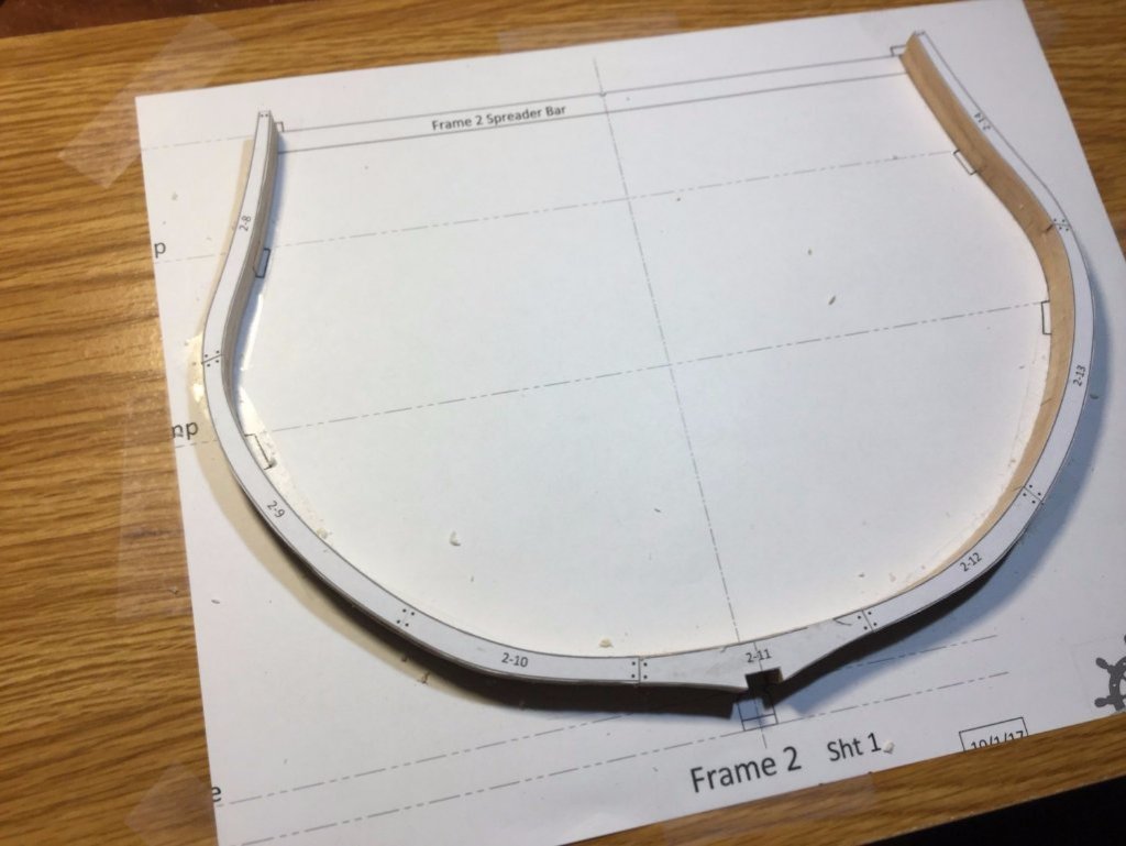
I finished cutting out all of the parts for the 9 frames. Each frame has 2 floors which have the notches that fit into the recesses on the keel. The first step was to file the notches smooth and get a nice fit. I used a piece of the blank I used to make the keel to fit the notches. Then the 2 floors for each frame were glued together while mounted on my piece of keel stock to keep the notches aligned. I used Glad-Wrap to prevent glueing the floors to the keel stock. All 9 floor assemblies were glued up. Next is to finish glueing up the remaining futtocks to create finished frames.
-
Hi Griphos! I use Elmer’s Rubber Cement. The template peels off and the residue rubs off easily. An acetone wipe and the frames are good to go.
-
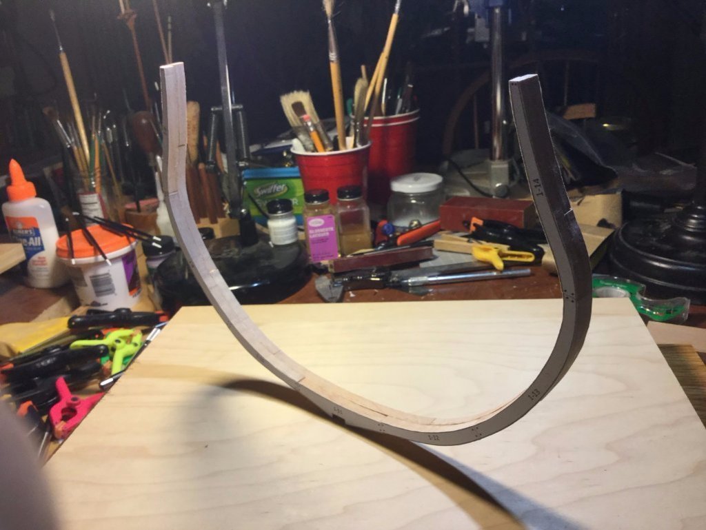
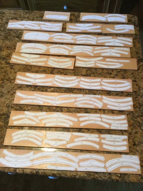
Before actually working on the keel, I decided to build the frames, so that I could more accurately fit the frame floors to the notches on the keel. The notches would be cut out after the keel and false keel were assembled and cut to length. I'm not so sure the sequence is all that critical, because the build jig also plays a role in determining where the frames go. I laid out the frame components (futtocks)on my beech billets, each 1/4" thick. The frames are double, so the finished frames are 1/2" thick or 16 scale inches. All the parts were then cut out on the scroll saw.
- 164 replies
-
- 20
-
-
Very impressive! Beautiful.
-
I might have overstated the simplifications in the frame construction. While the frames themselves have no chocks or scarfs (like the frames on the MSW Triton group build), the disposition on the frames on the keel does have the frames rising on the keel moving aft, as well as the frames narrowing toward the stern. The easy out would have been to have made all 9 frames identical and sitting on a flat, straight keel with no “rising wood”.