DocBlake
-
Posts
1,811 -
Joined
-
Last visited
Content Type
Profiles
Forums
Gallery
Events
Everything posted by DocBlake
-
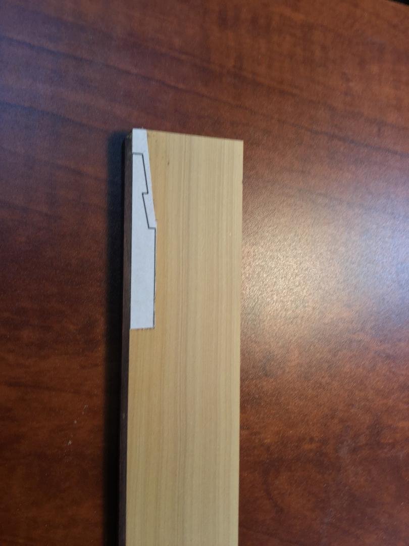
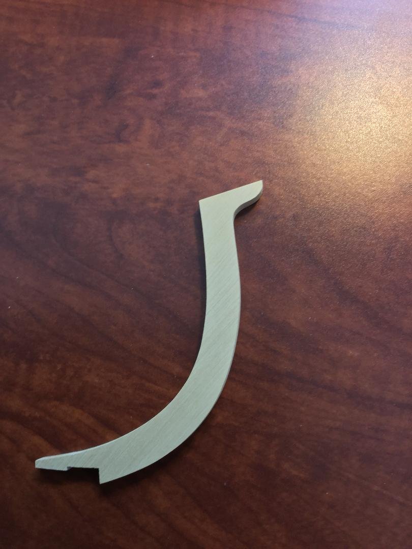
 I question making the stem out of a single timber. Both Harold Hahn and Bob Hunt left the stem as a single timber. It's a large piece of wood with a pretty serious curve in it. I doubt that a large enough tree could be found with the natural curve in it to serve as the stem. If the stem were cut from a single straight timber , that piece of wood would have to be almost 6 feet wide! I doubt there were many trees that were more than 6 feet in diameter while being suitable for shipbuilding! My conclusion is that the stem would almost certainly be scarfed together. Here is a proposed scarf for the stem. I have no real plans that show this...it just makes sense to me. Thoughts?
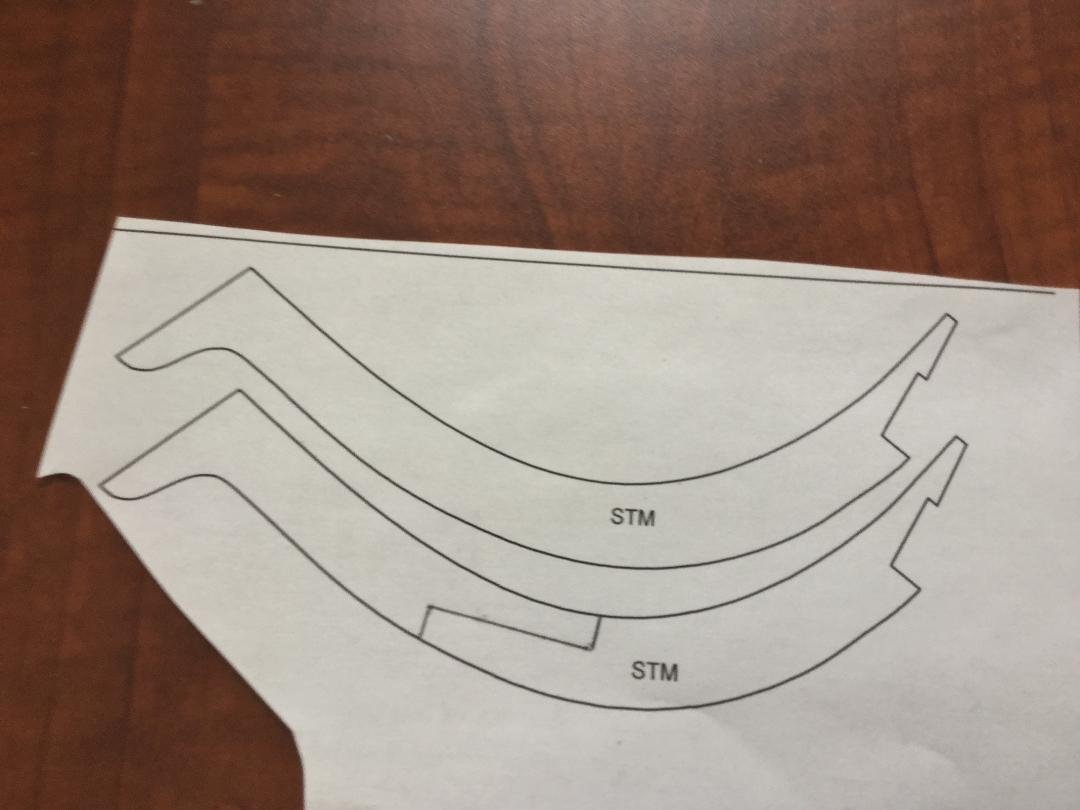
-
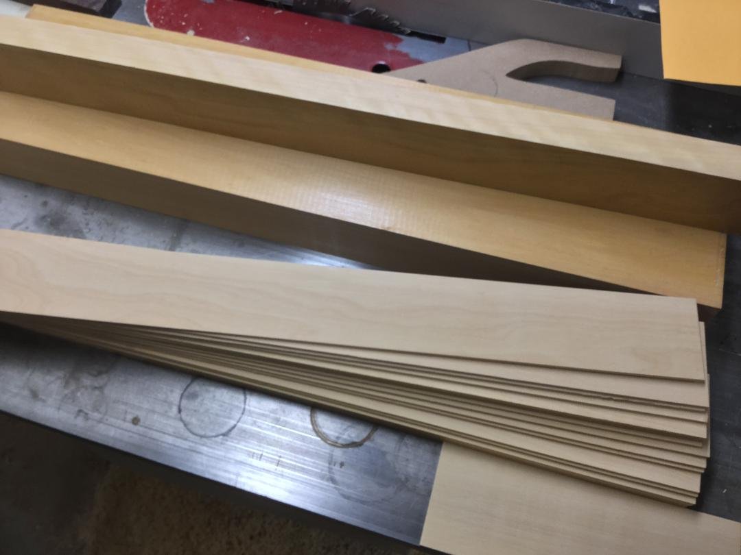
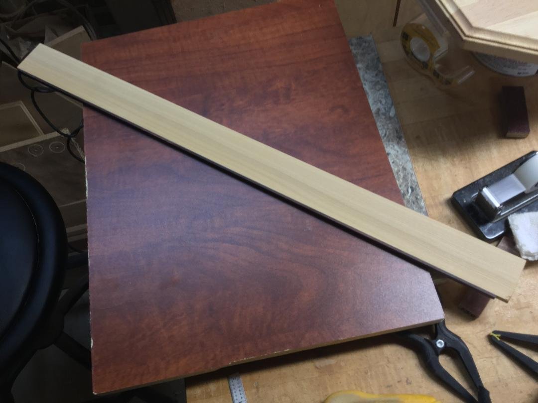
Thanks for looking in, guys! I started working on the model by milling my wood. The frames are double frames, sistered together. each half-thickness frame is 9/64" thick, with a finished frame thickness of 9/32". almost all the billets are 9/64" thick. The stem and keel are supposed to be constructed of two thicknesses also, but I simply made them 9/32". The photos show some of the milled wood, my keel blank with the false keel attached , the stem and the template for the keel scarf rubber cemented to the keel blank.
- 45 replies
-
- 11
-

-
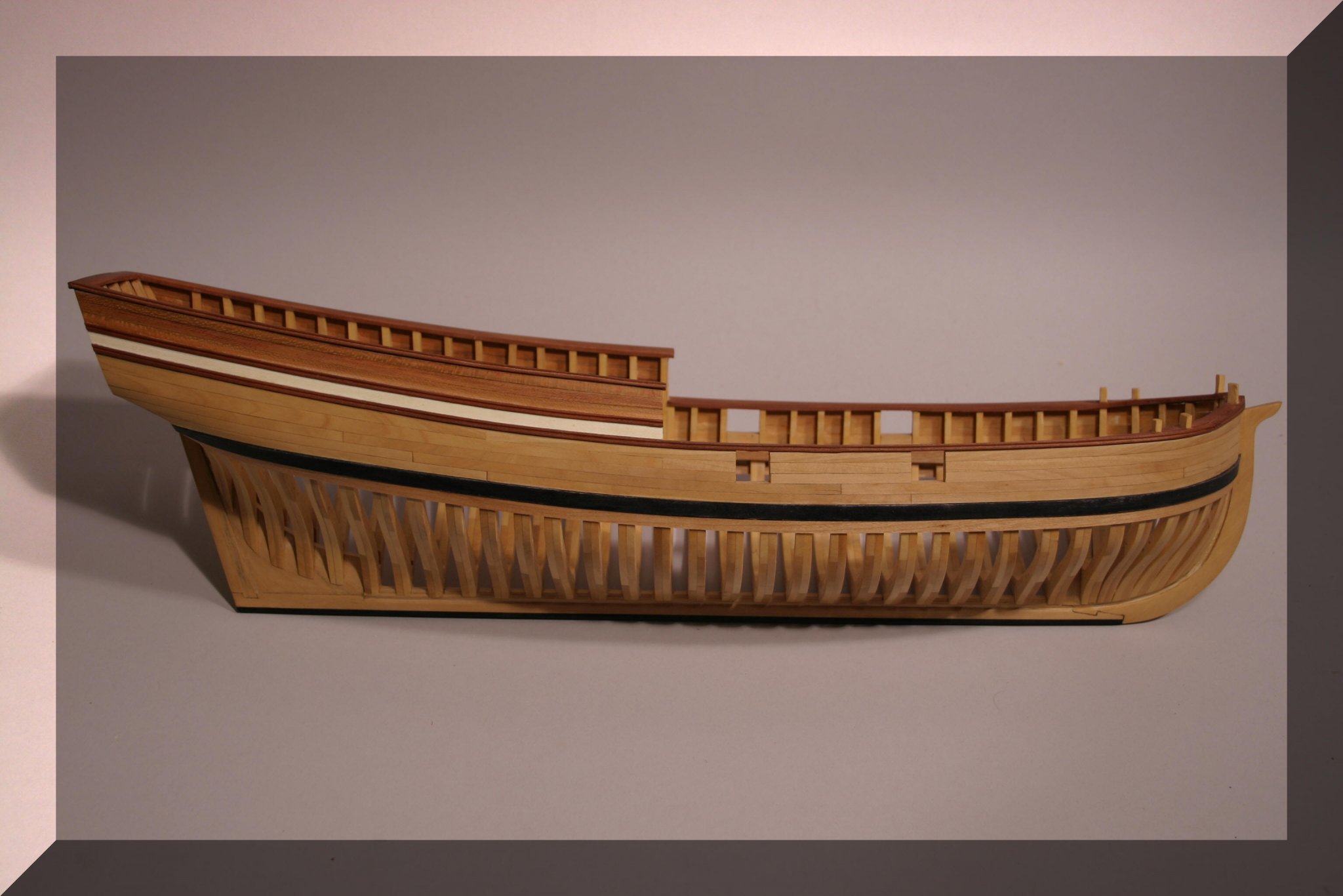
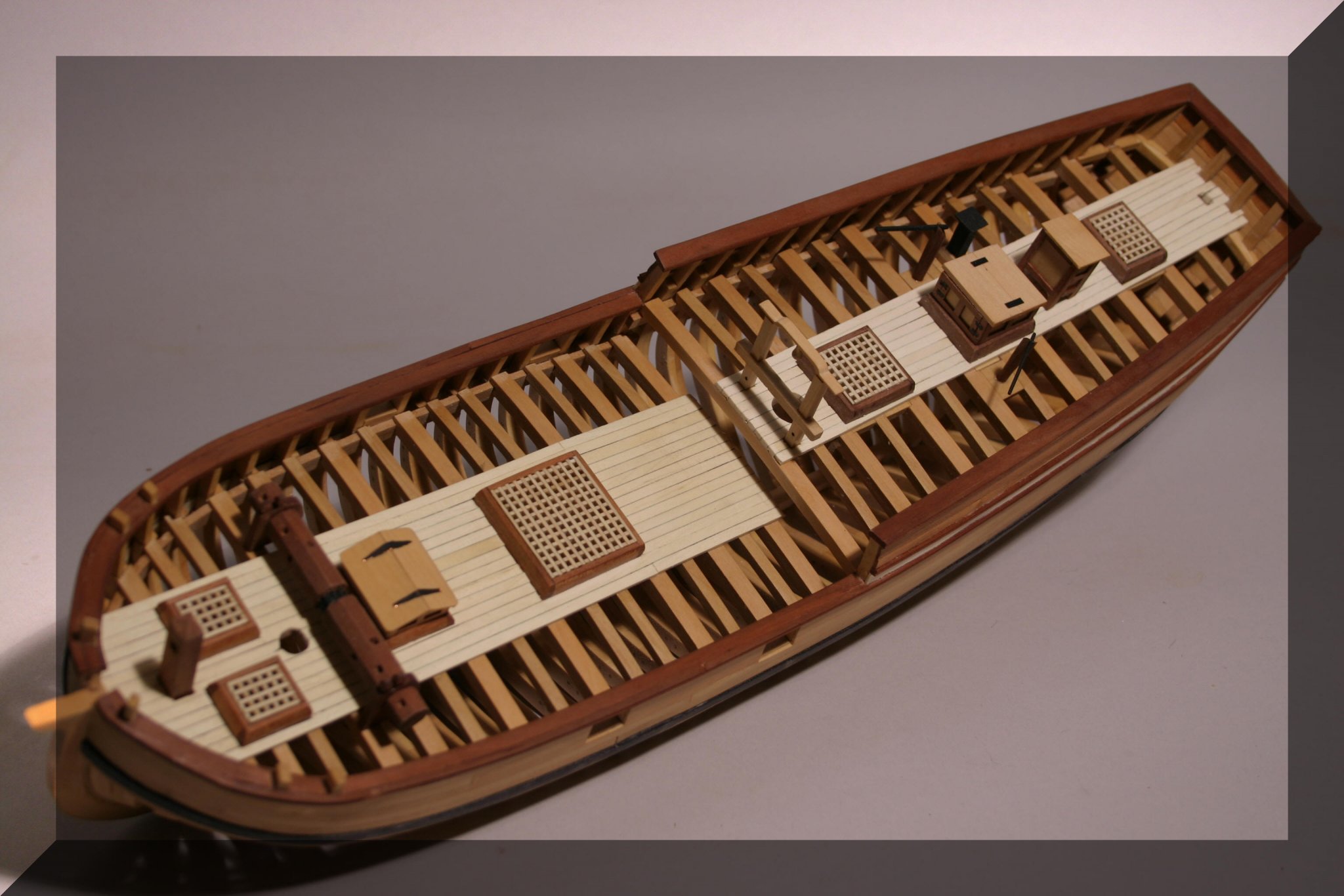
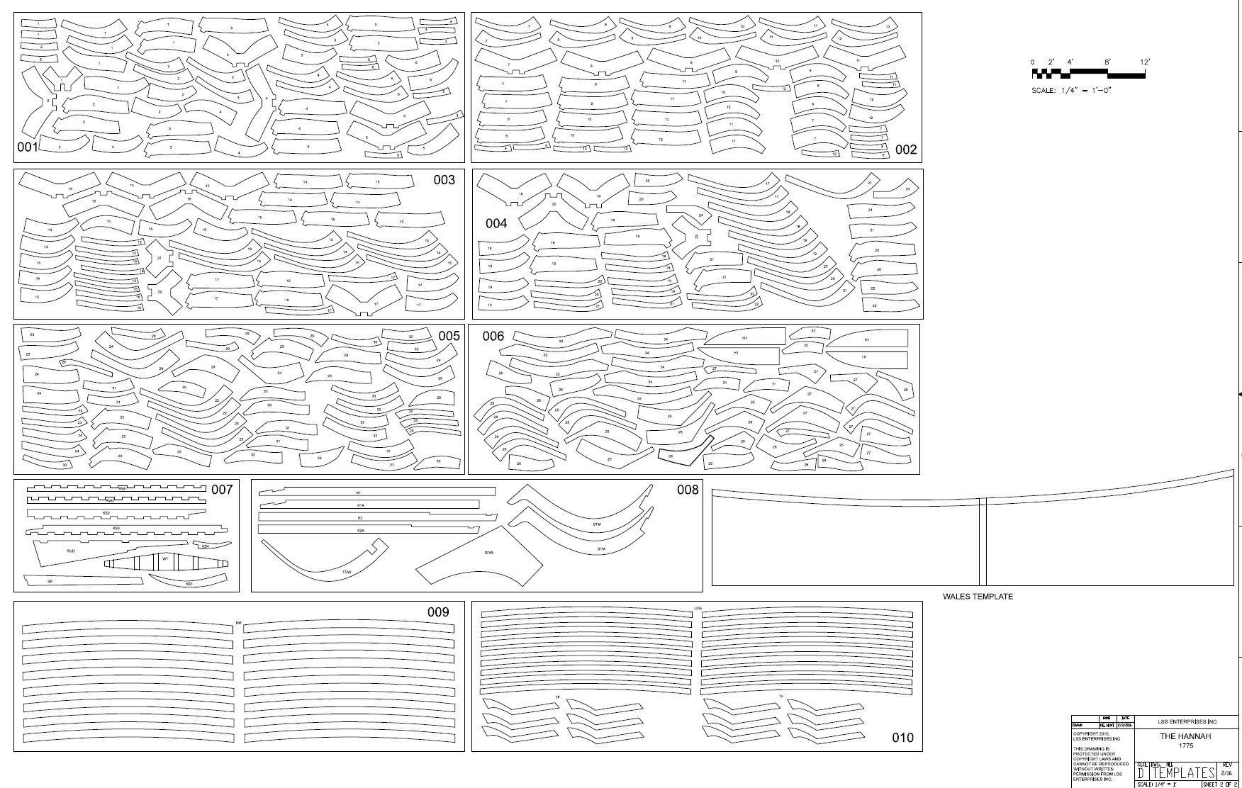
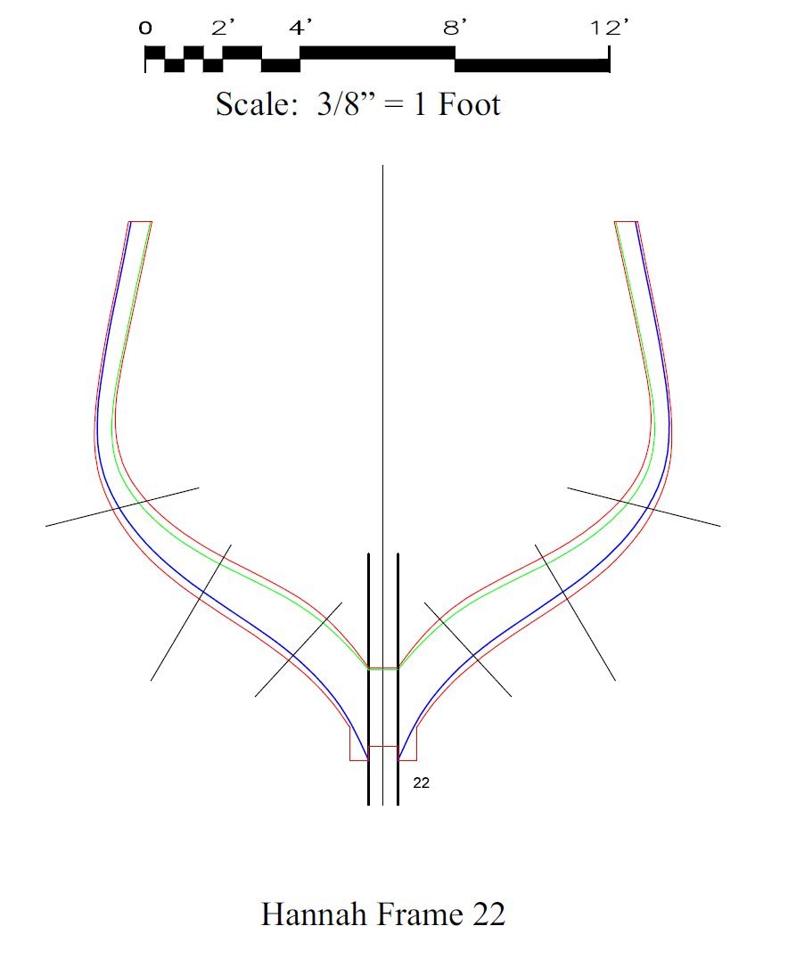
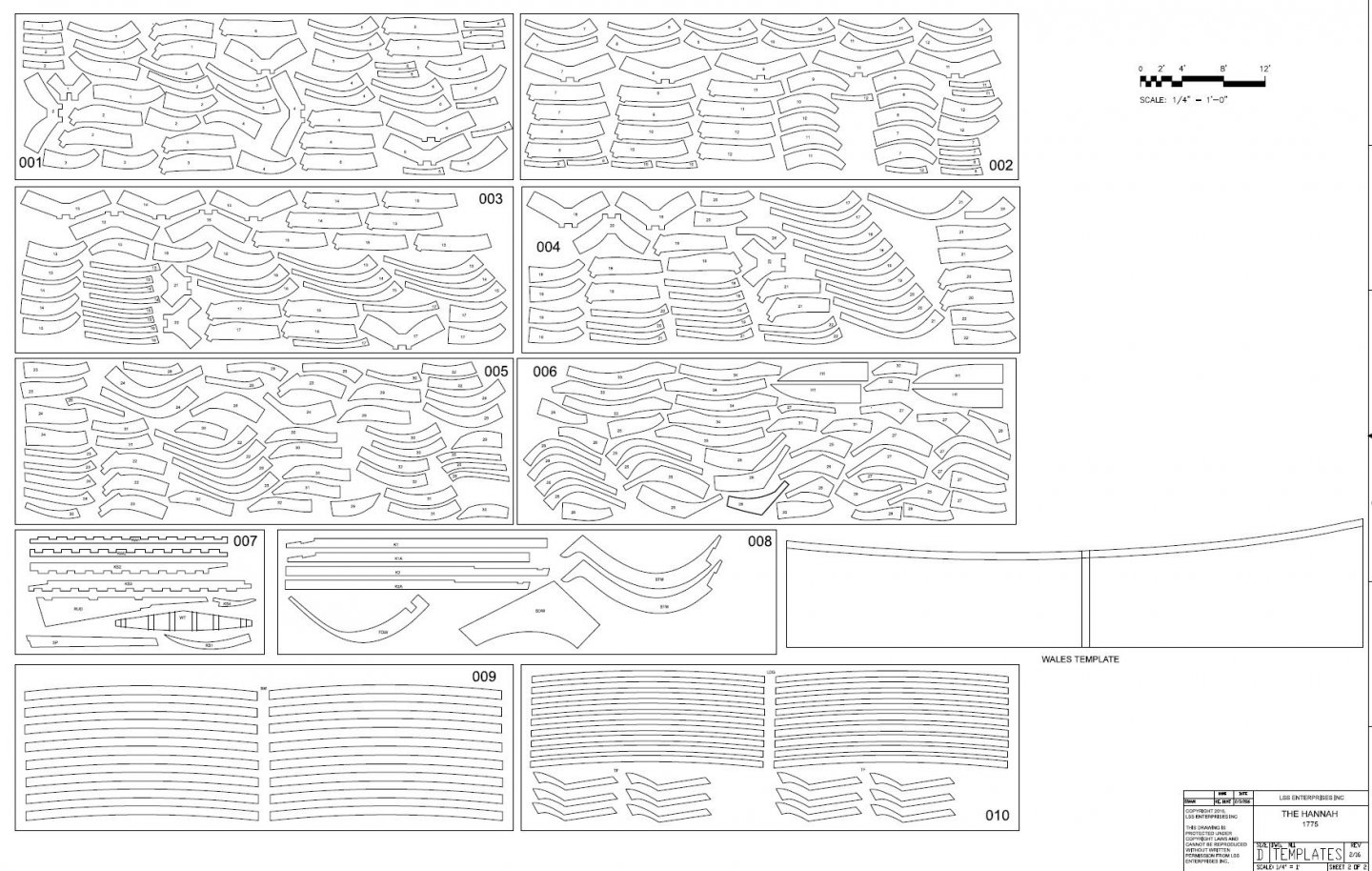
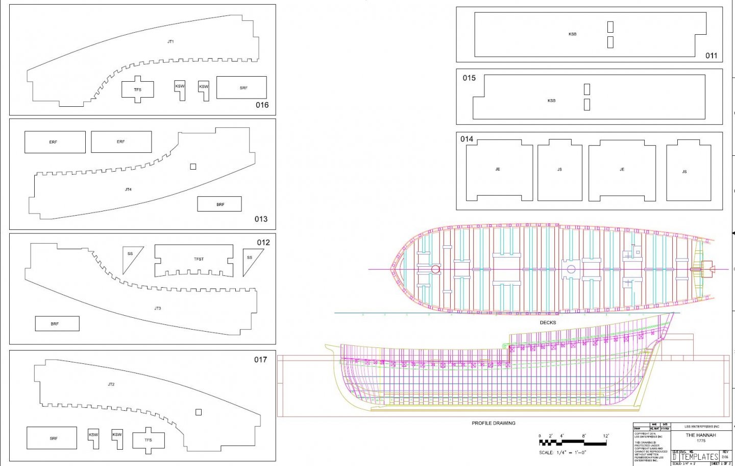
This will be my build log for a scratch-built, 1:32 scale, plank-on-frame, admiralty style model of "Hannah", purportedly the first armed ship recruited into Washington's navy during the Revolutionary War. I've wanted to do a full hull scratch build at this larger scale, but what ship? The choice was not completely arbitrary. Even a 5th or 6th rate frigate in the Royal Navy would be 4-1/2 feet long at this scale, not including the bowsprit! Obviously I had to look elsewhere. I settled on Hannah because it is significantly smaller (this model will be 24" long with a 6" beam) and there was a lot of documentation out there regarding the model. I have Hahn's book as well as his plans for "Hannah" to use as a reference. The actual building plans were drawn by Bob Hunt, based on Hahn's original drawings, and were done in 1:48 scale. I had them resized to 1:32. The drawings show each individual futtock and include detailed drawings of each frame, including bevel lines. The model will be built in an upright jig, as was my 1;32 Armed Virginia Sloop and my 1:32 "Blandford" cross section. The frames, stem, keel and stern will be boxwood. I'll decide on other woods as I move along with the build. Thanks for looking in! Here are some shots of the plans and Bob Hunt's "Hannah" model along with a link to his website. https://www.lauckstreetshipyard.com/


- 45 replies
-
- 14
-
-
I'm just beginning this build as a scratch project in 1:32 scale. I'd love to see you back at this build, Mario! With no real instructions this will be a challenge. Hopefully you can answer a few questions as they come up! Thanks for any help you can offer. Please check your PM!!
-
So you say you want to work with wood? All risk is relative! This list will turn your hair white! https://www.mountainwoodworker.com/articles/toxic_woods.pdf
-
Thanks for all the kind words, guys. Much appreciated! I especially want to thank Mike R. (Mike41) for all his hard work in drawing the plans, building the prototype, and listening to me bitch about this build! 😀😀😀 Thanks, Mike!
-
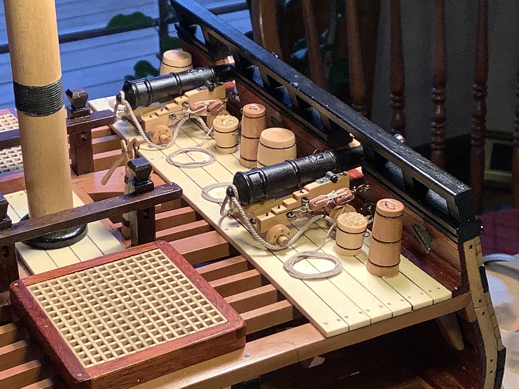
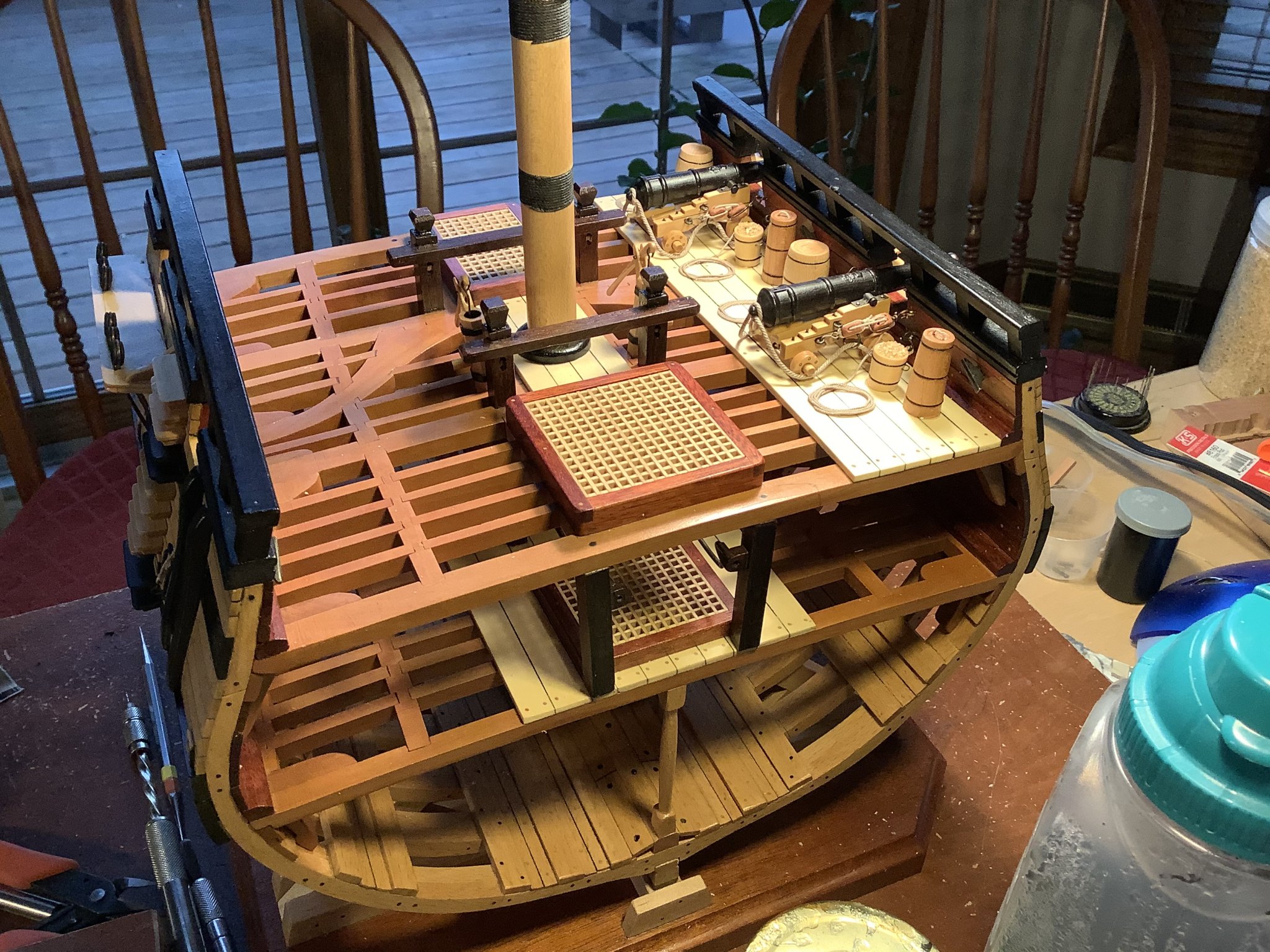
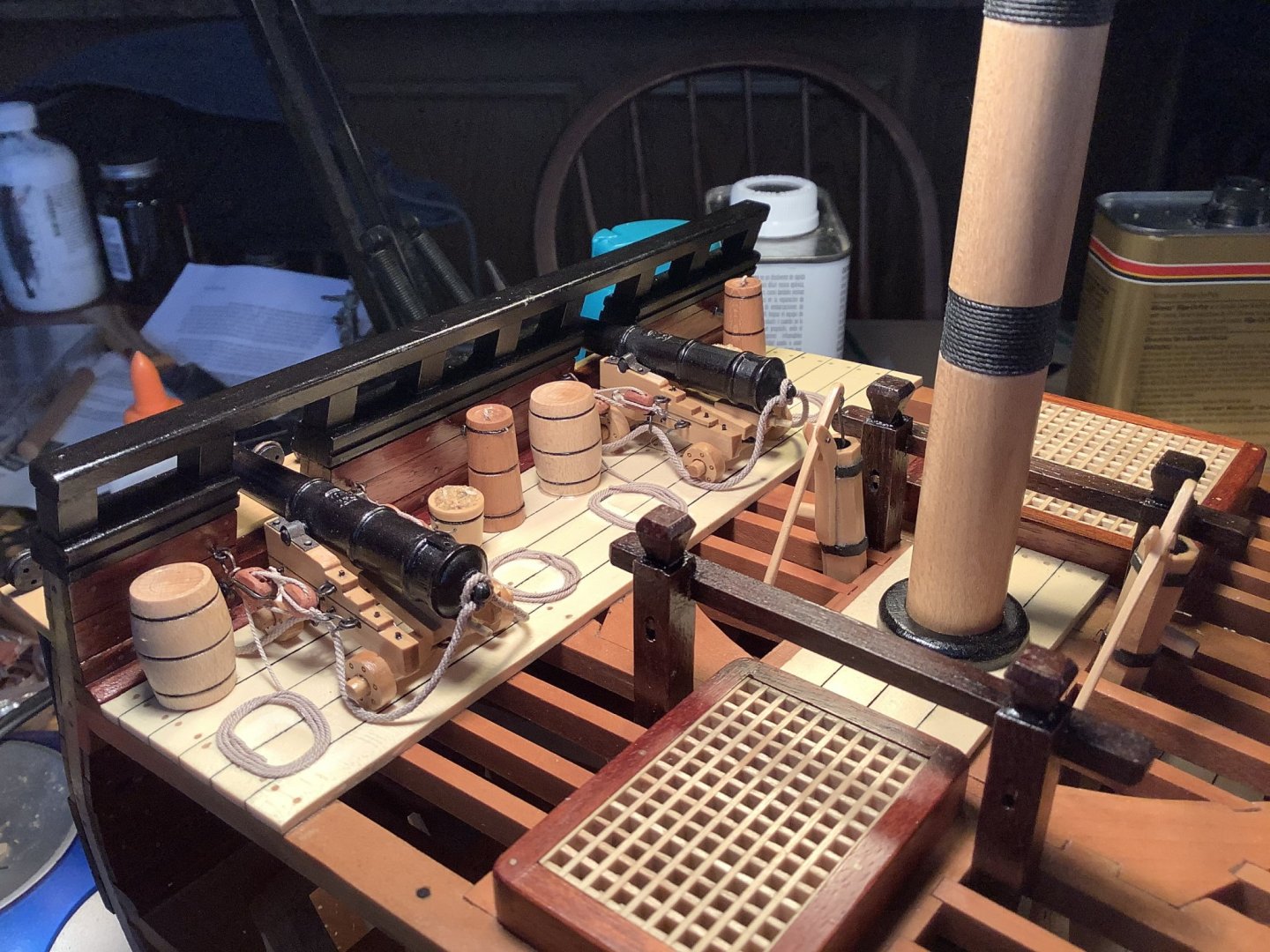
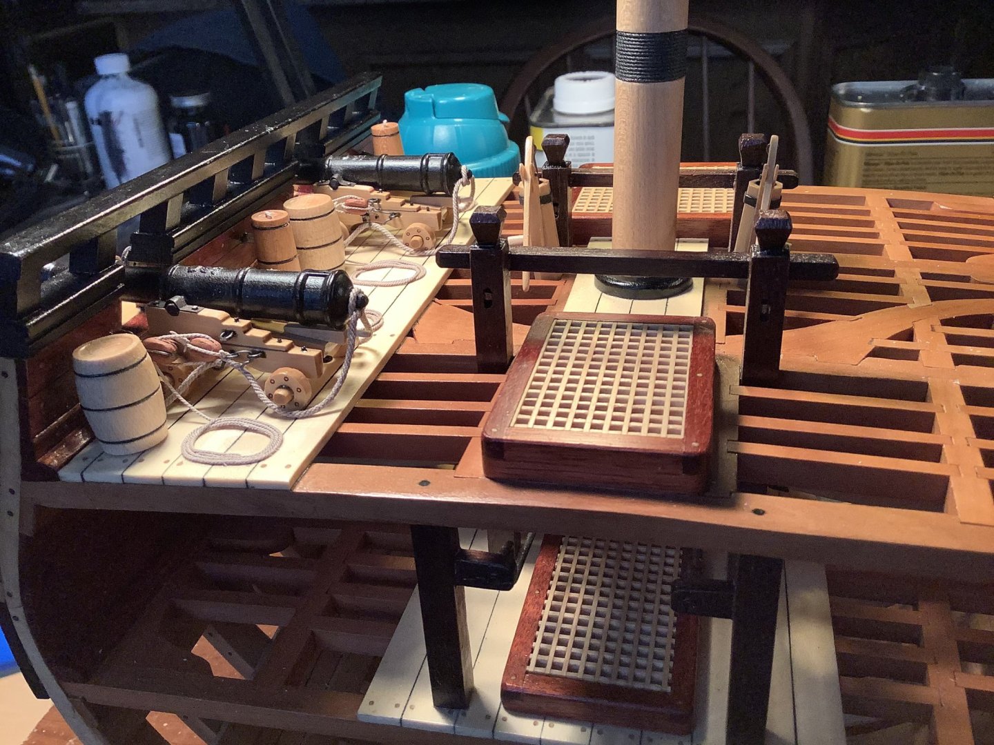
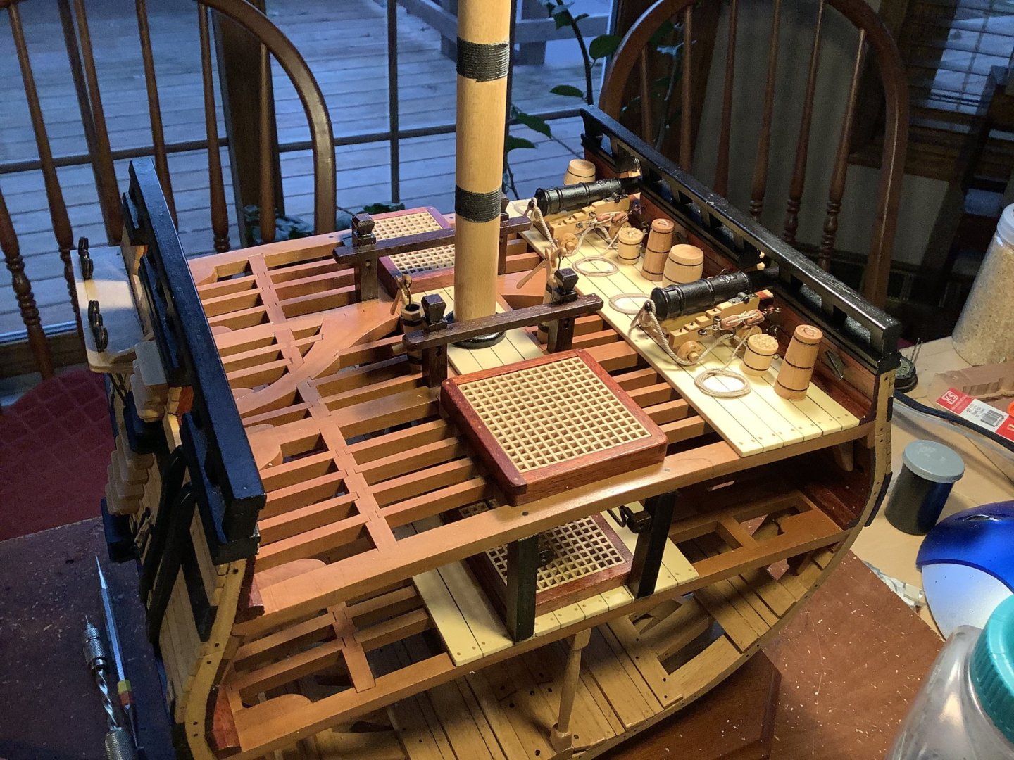
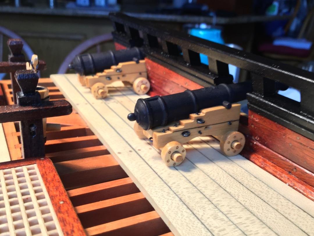
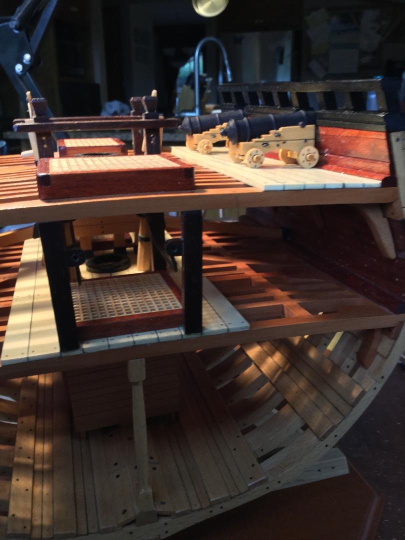
Thanks, guys!! FINALLY FINISHED!!! I rigged the guns and placed some equipment at each battle station to complete the model. I'll post a few more shots, including the model in it's case, tomorrow.


- 164 replies
-
- 24
-
-
Beautiful work, Bob!
-
Can i live without a BYRNES TABLE SAW
DocBlake replied to shihawk's topic in Modeling tools and Workshop Equipment
You CAN live without one...but why would you want to? -
Even POF kits rarely construct the individual frames as originally built (chocks etc.), and the disposition of frames is rarely accurate. This is done for ease of construction. That said, Bob Hunt’s Lauck Street Shipyard POF models were superb. His “Kingfisher” is the greatest kit ever produced, IMHO. Too bad they are no longer.
-
Bench Top 5" Disk Sander
DocBlake replied to DocBlake's topic in Modeling tools and Workshop Equipment
I think you'll really like the variable speed feature! -
I have a Byrnes disk sander, and it is a remarkable tool. I love it!!! But I hate changing paper back and forth for different tasks. The bulk of my work with the Byrnes is with the fine grit (180). I occasionally could use coarser grit, like 100. I decided to make life easier by buying a bench top sander that I can equip with coarse paper. It cost me $40 at our local Menard's. The tilting table mechanism and miter gauge are cheap, but I simply set both at 90 degrees with a try square and I don't anticipate changing them often. The best feature is a variable speed control. Wonderful!! I really wish we could have that on a Byrnes! https://www.menards.com/main/tools/power-tools/sanders/performax-reg-1-1-amp-corded-5-bench-top-disc-sander/jd2504/p-1489990860962.htm

-
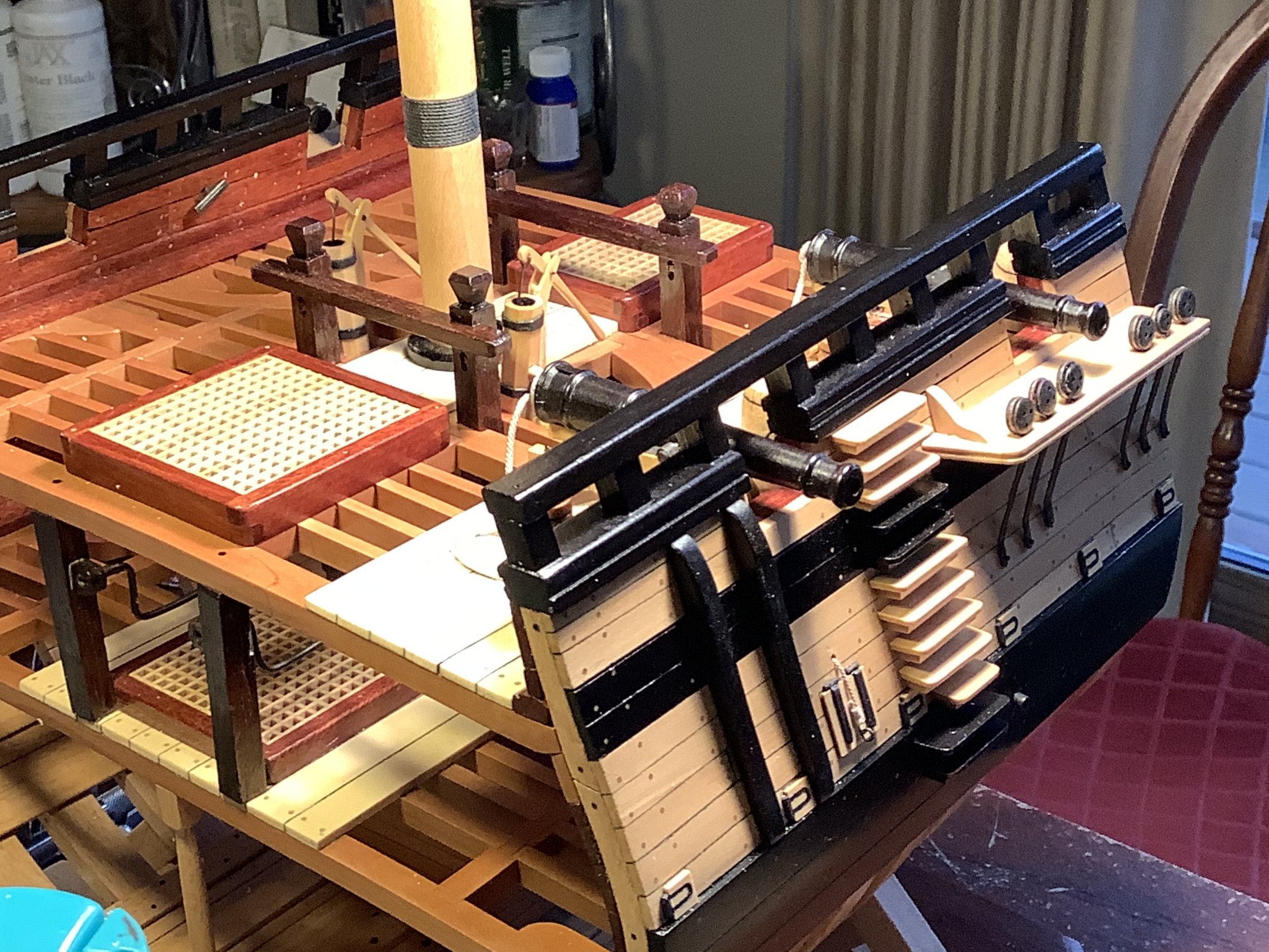
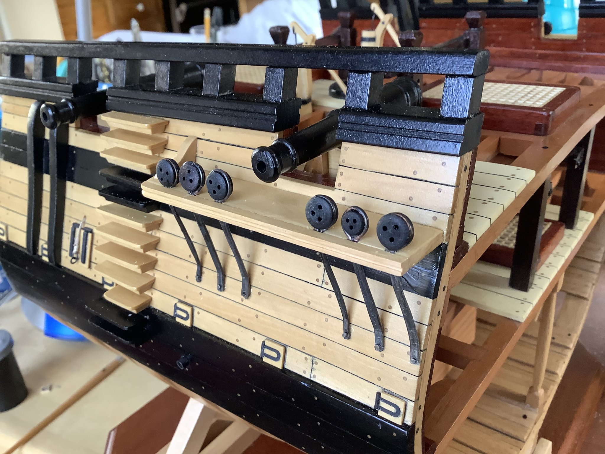
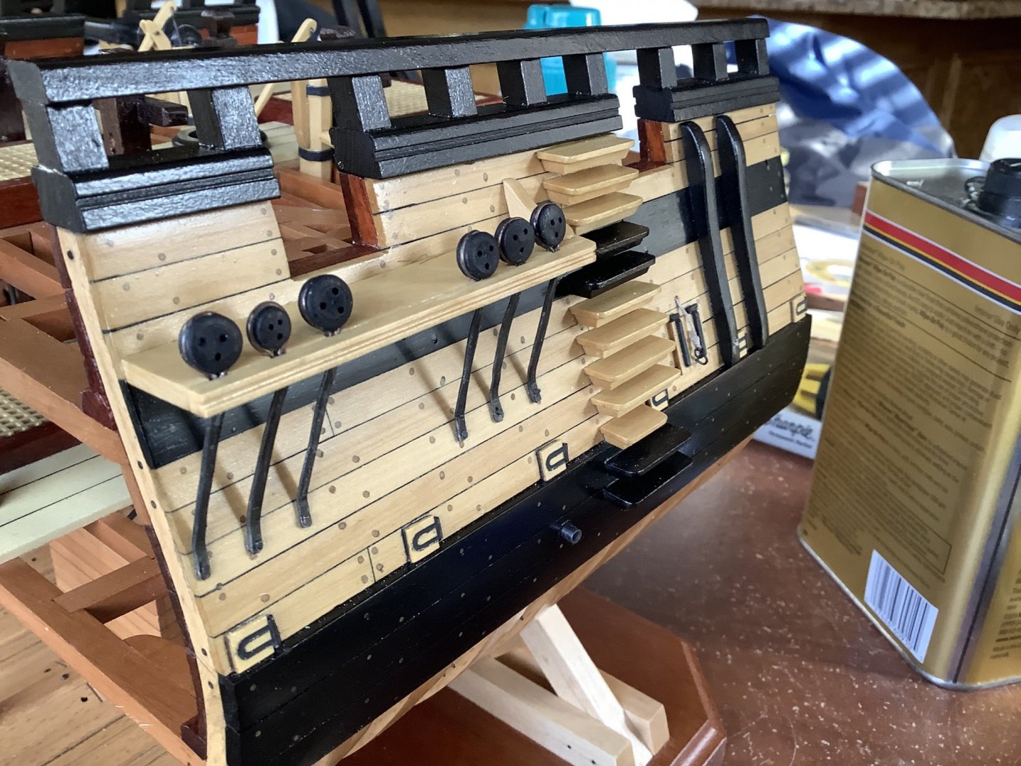
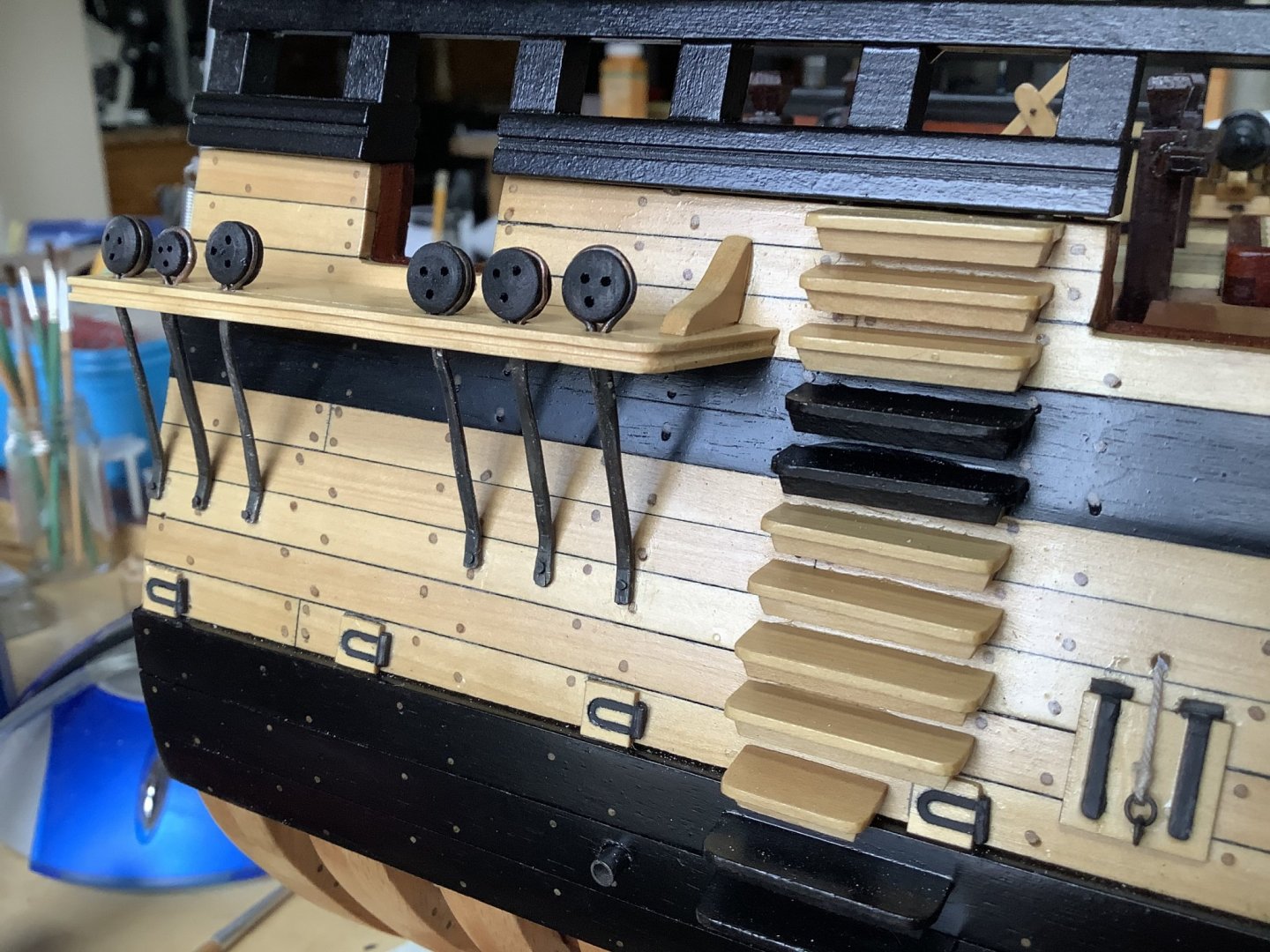
The exterior of the model is complete. I mounted all the deadeyes and chainplates and glued the retaining strips to hold them in place. The chainplates were nailed to the hull through pre-drilled holes and secured with a drop of CA. The chainplates were fixed to the channels in their notches with a little gel CA. The finished channels have a decorative groove cut in the outside edge, and knees to counter the upward stress the shrouds would put on the channels. All that's left is to rig the cannons, and add some kegs, match tubs and tools to the two battles stations on the gun deck.


- 164 replies
-
- 21
-
-
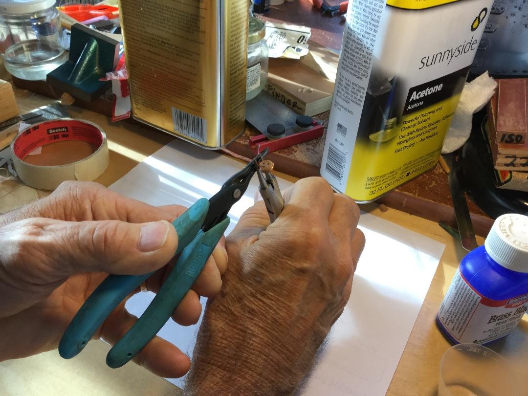
This is the sequence for making the deadeye stropping and chain plates. This simple strap style of chain plate was in use by the British Royal navy before 1760. Blandford was launched in 1720. I started with a length of 18 gauge copper wire (adjust based on scale and deadeye size). I wrapped it around the deadeye (a sacrificial deadeye, not the final one) and then clamped the two wires about 3/16" from the deadeye with a pair of pliers. With another pliers I squeezed the two wires between the first pair of pliers and the deadeye to create a tight strop with two parallel copper wires. I then soldered the two copper wires together. Be careful not to solder too close to the deadeye or you won't be able to remove it. Once soldered, remove the sacrificial deadeye (you can use it again!). File the soldered "strap" flat and remove any excess solder. Blacken the chainplate and install the finish deadeye. Mine were dyed black. Bend the chainplate to fit the channel and butt up against the hull. Drill a hole in the end of the chainplate, and with an awl mark the location on the hull where you'll pin the chainplate. Use the hole in the chainplate to mark the location. Drill that hole. Install the chainplate/deadeye assembly.


- 164 replies
-
- 18
-
-
I need to get this model finished! I made my own blocks from swiss pear. They are 8 scale inches long, or 1/4" on the model. The single blocks are cut from 1/8" X 3/16" stock, and the double blocks are from 3/16" square stock. The sequence is: -Mark the location of the sheave holes and drill them through with a #60 drill -Connect the sheave holes with a groove, using a curved X-Acto blade. -Round one end of each block, then cut them off at 1/4" and round off the other. -File stropping grooves into the block faces. -Treat with boiled linseed oil to darken.
- 164 replies
-
- 14
-
-
HMS Pickle by mtbediz - FINISHED - 1:40
DocBlake replied to mtbediz's topic in - Build logs for subjects built 1751 - 1800
Great progress, Mustafa! -
Thanks Michael, and everyone for the "likes". Gregory: The cannon barrels are 3-1/8" or 79 mm from cascabel to the end of the barrel.
-
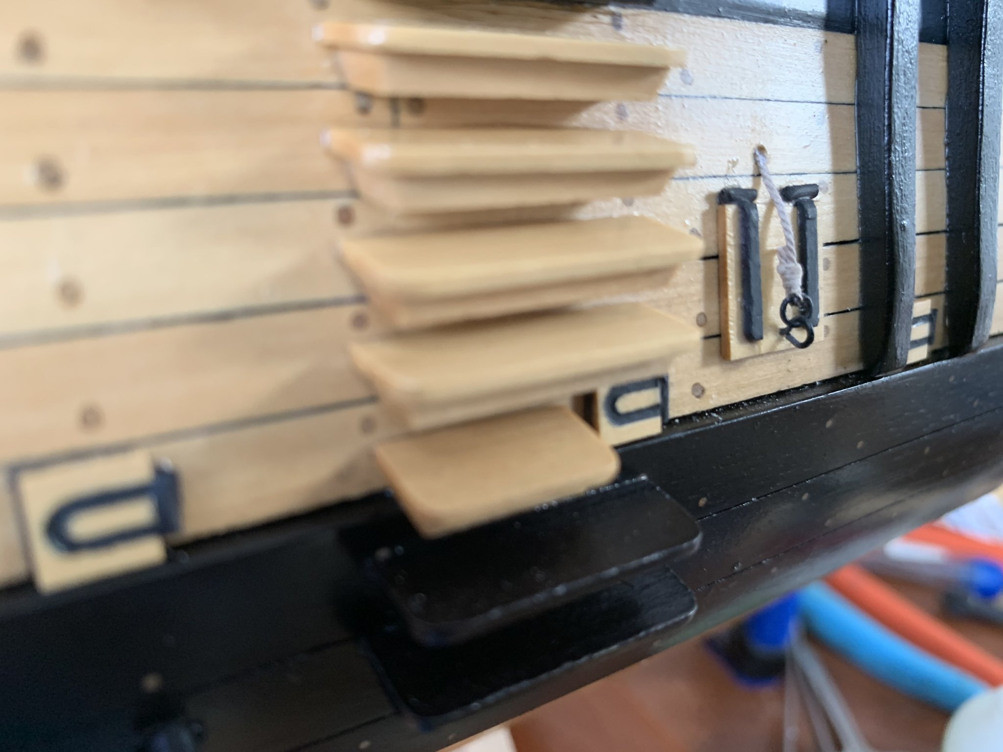
Thanks, guys! Closer to done. Sweep port and ballast port covers installed. The ballast ports need ring bolts and line to open them. No poly yet. All that’s left on the outside of the hull are channels, dead eyes, chain pump dale discharge ports and chain plates. Just finishing those up.
- 164 replies
-
- 24
-
-
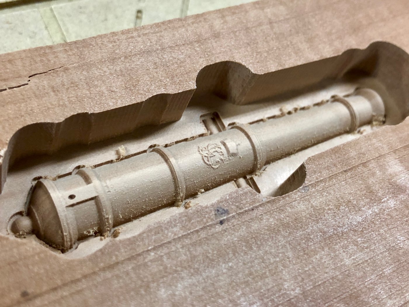
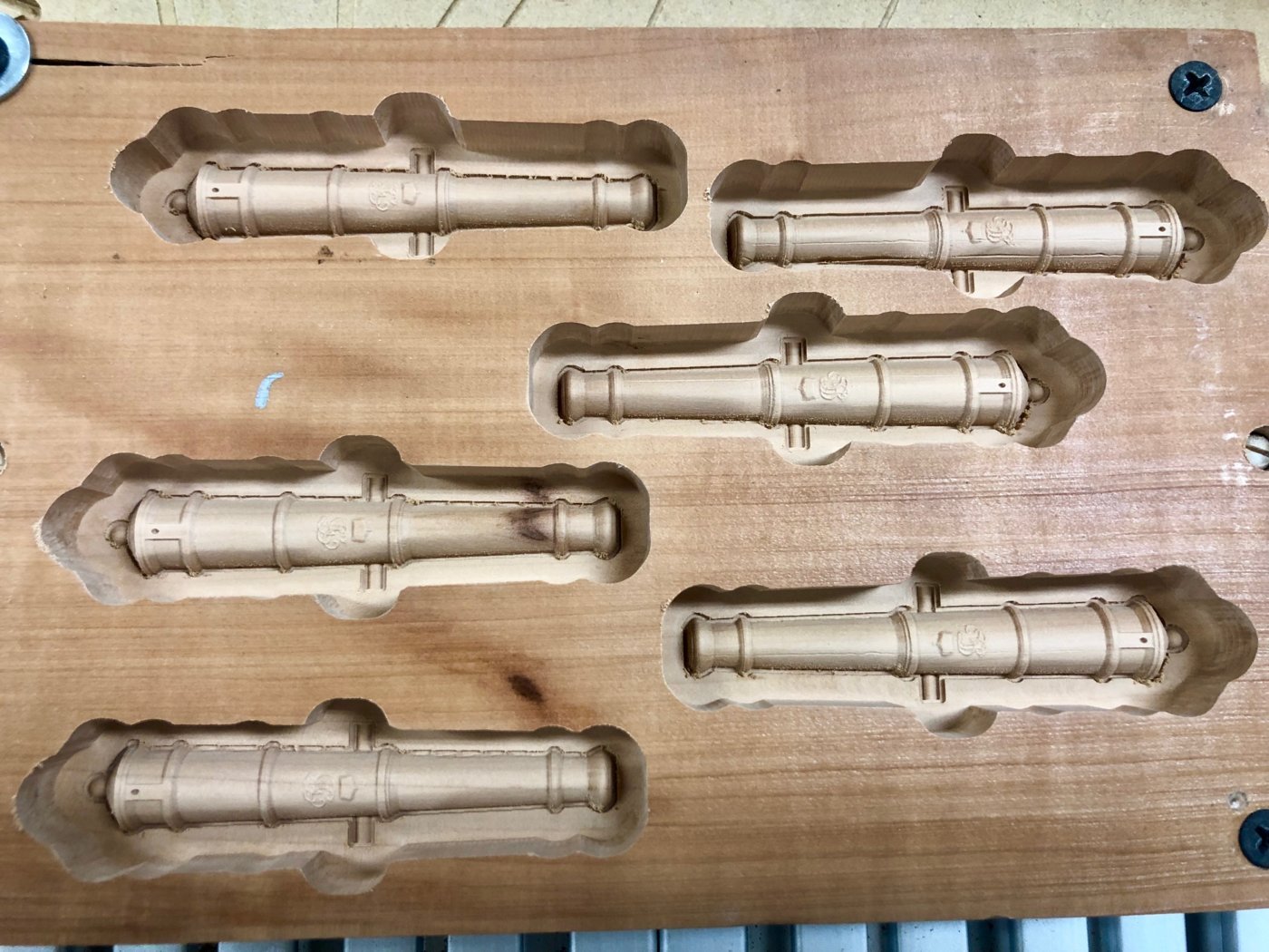
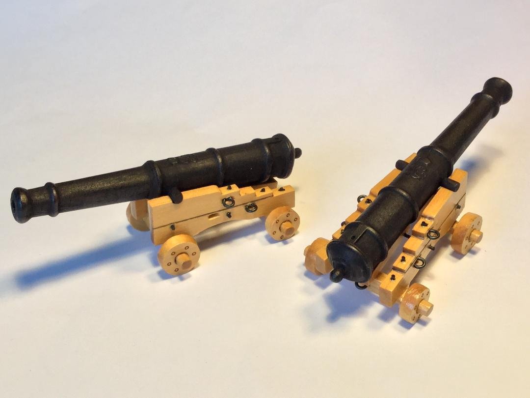
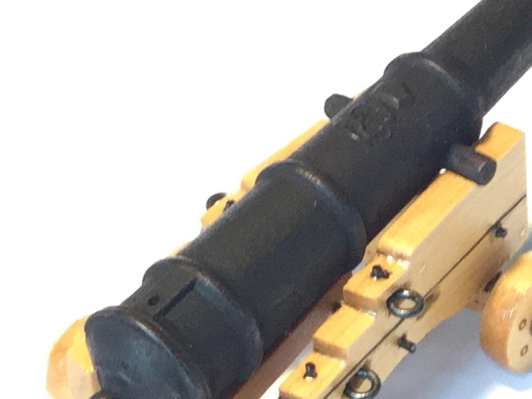
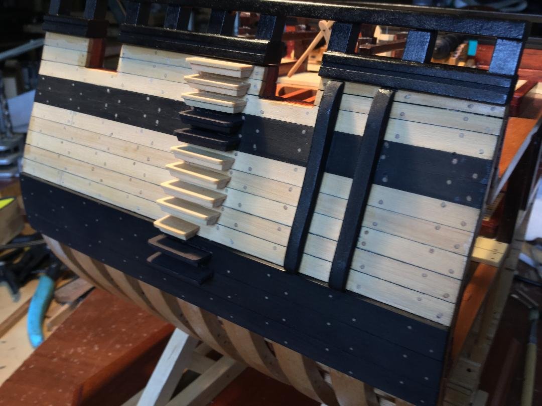
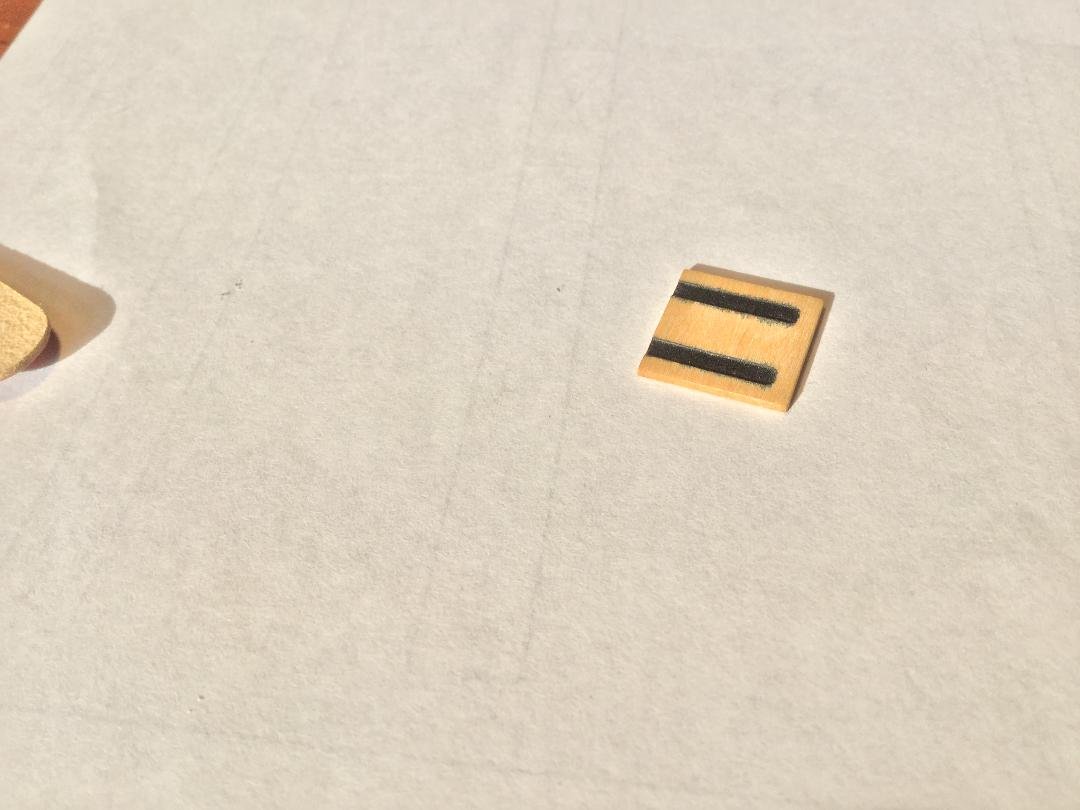
Finding 6-pounder cannon barrels in 1:32 scale proved to be very difficult. Since I had been involved in conversations with my cyber friend Mike (one of my 17th Century Battle Station partnerss), we speculated as to whether we could cut the guns with his CNC setup. After a lot of hard work on his part, Mike sent me four 6-pounders CNC cut out of swiss pear. All I had to do was clean them up, dye them and give them a coat of poly. Look closely at the barrels. You can see the touch hole and the cypher of King George I, the monarch in 1720. Mike also laser cut the carrieages for me. I laso installed the entry steps and the fenders.

- 164 replies
-
- 27
-
-

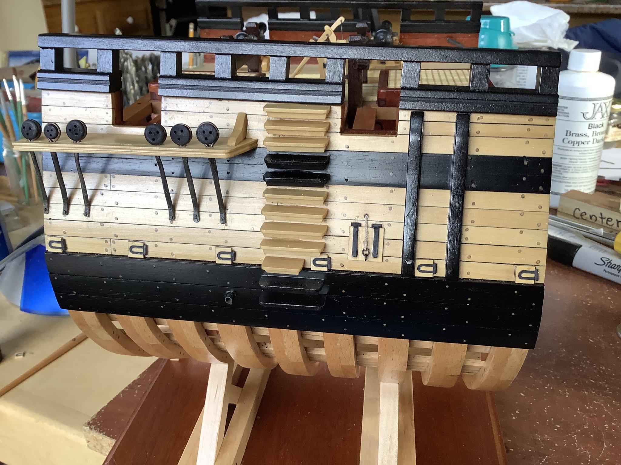
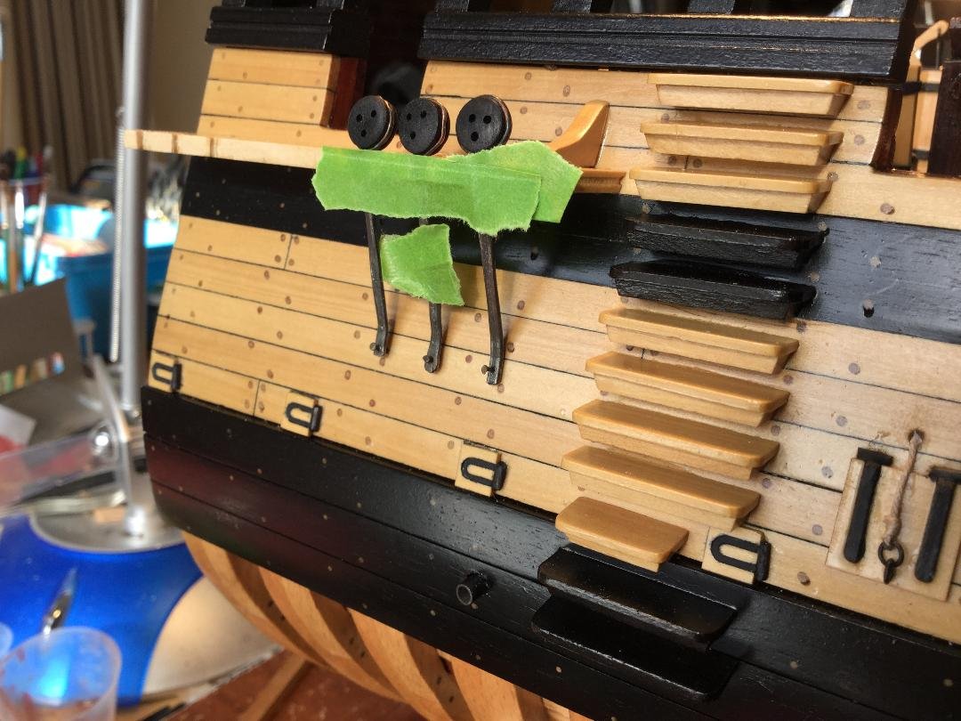
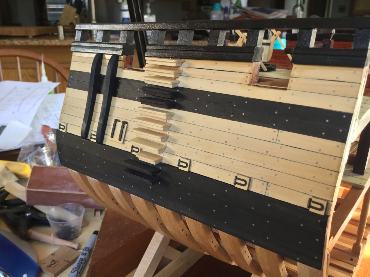
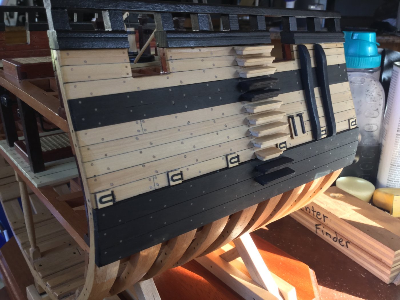
-
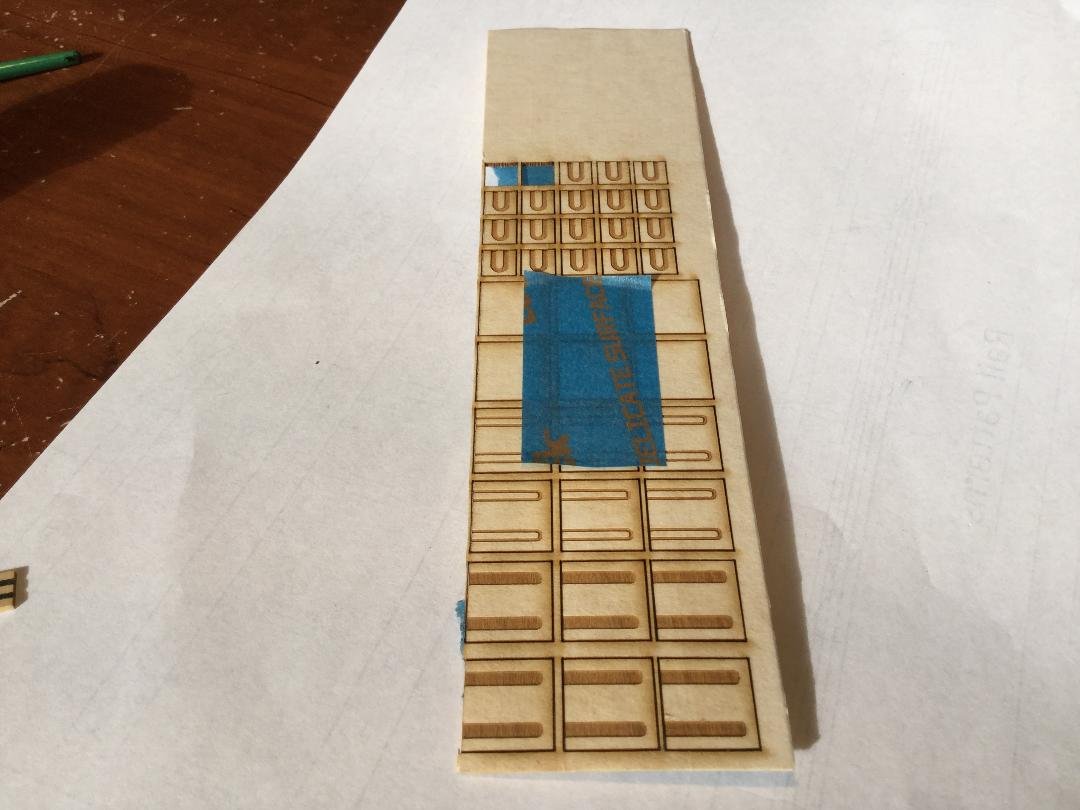
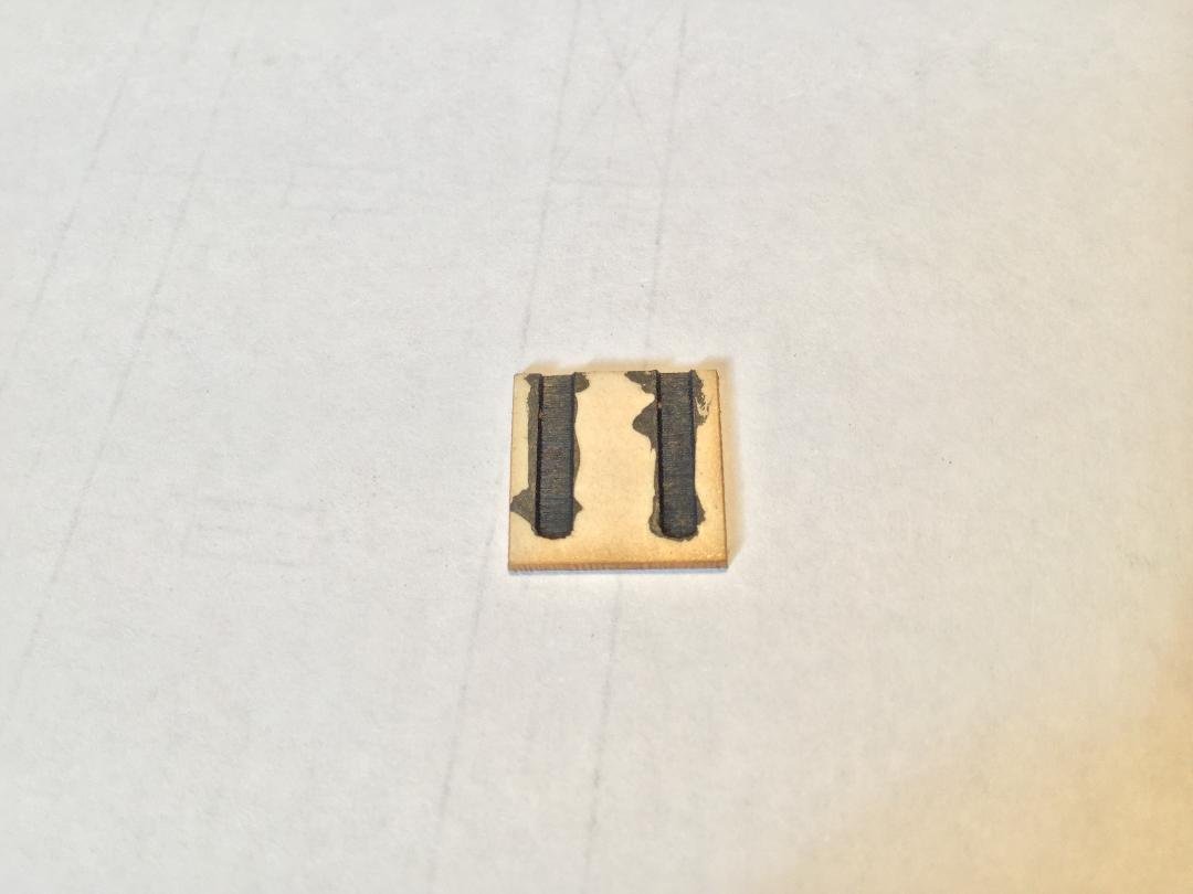
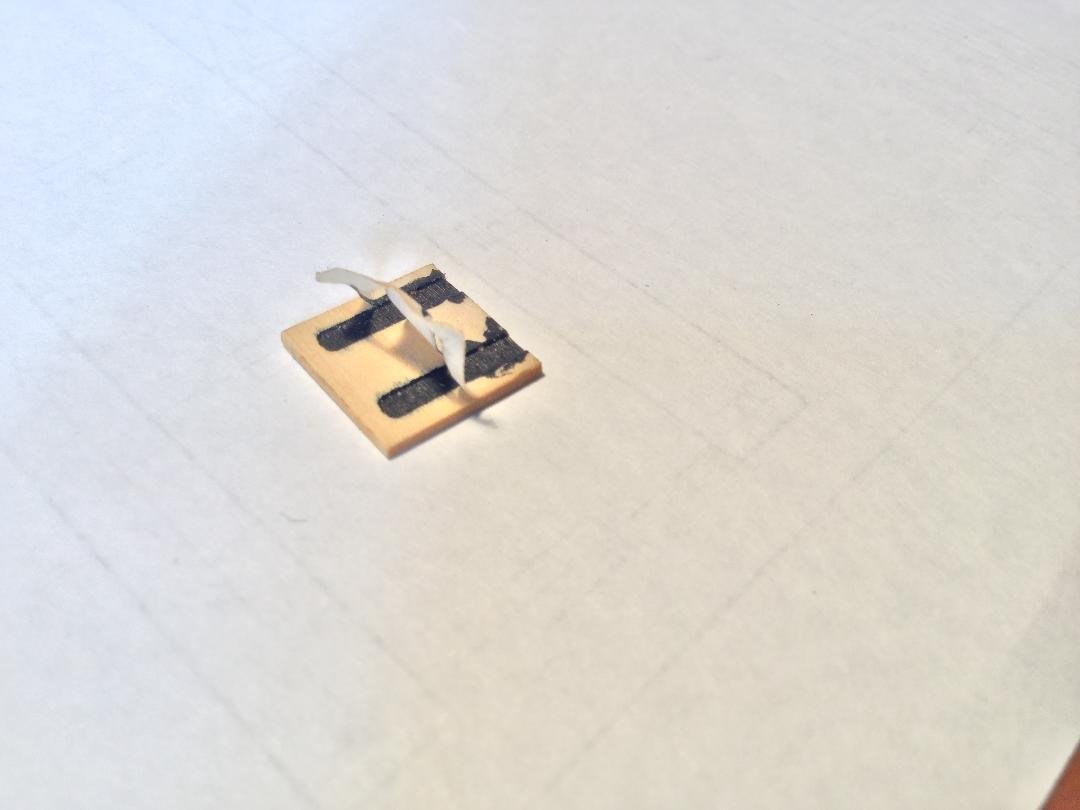
I'm beginning to work on the final details on the exterior of the model. There are 6 sweep port covers and one ballast port cover per side. When the model was designed, the idea was to keep the framing simple, so understandably the sweep ports and ballast ports were not framed in. In the original ship, the port covers would have sat flush with the outboard planking. In the model, they will be glued onto the planking. The plans call for 1/16" stock for these parts. I'm using boxwood so I thought I could go thinner - I used 1/32" thick boxwood. A soft wood like basswood wouldn't hold up at 1/32". I also need a way to add those horseshoe shaped hinges to the sweep port lids. I talked to my good friend Mike , and he offered to cut the parts out of 1/32' boxwood and etch the hinges for me! Then it was a simple matter to paint the hinges. Mike left masking tape on the good surface of the boxwood so there is no laser scorch on the good face, and it masks the wood where the hinges are, so all I had to do was slop on the paint and let it dry. Once dry, peel off the masking tape, and nice clean hinges result. Here are some pictures. Thanks, Mike!


- 164 replies
-
- 13
-