DocBlake
-
Posts
1,811 -
Joined
-
Last visited
Content Type
Profiles
Forums
Gallery
Events
Everything posted by DocBlake
-
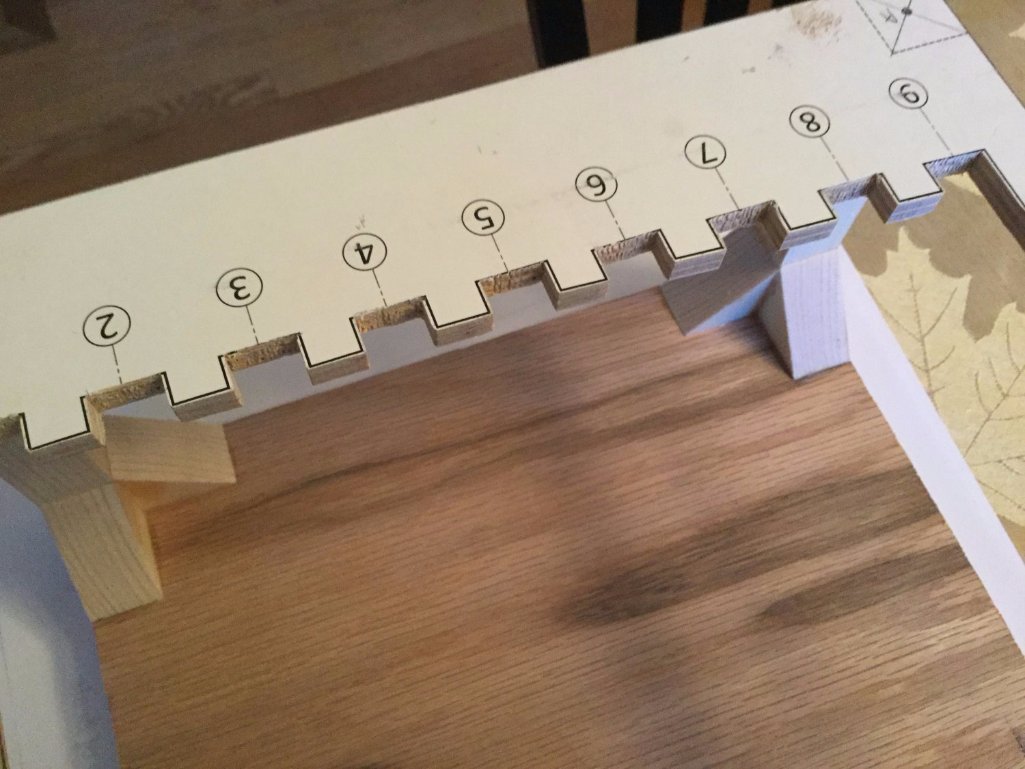
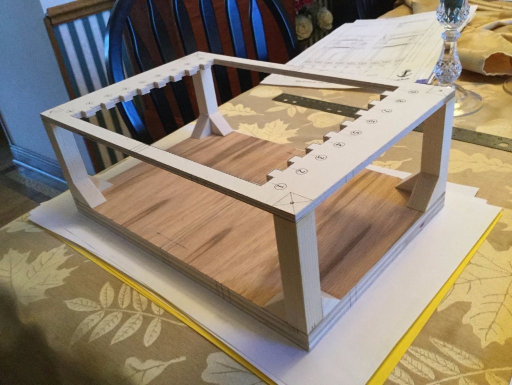
 Thanks for looking in, guys! My first decision was materials. I decided to make the keel, keelson and frames out of European beech. I bought 2 big slabs of European beech on the internet. I've never had the opportunity to work with European beech so this was interesting. It looks like oak with small silver flecks in it, but is more tan with a touch of red in color. The grain is probably too pronounced for 1/64 or 1/48 scale, but is fine at 1/32 or 1/24. The first step is making the building jig. The base is 3/4 plywood and the top is 1/4" ply. I cut the notches small so I can file them making the frames fit snugly. The keel is fixed to the buildinf jig by brass pins, which will then be used to mount the model for display. The next task is building the keel.

- 164 replies
-
- 20
-

-
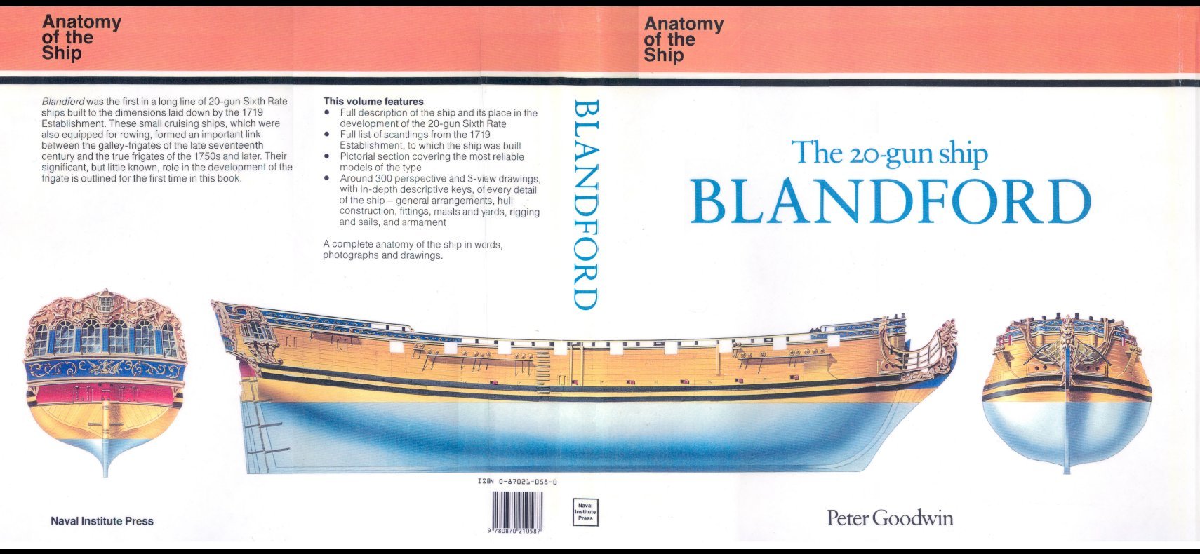
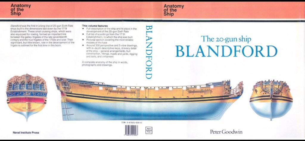
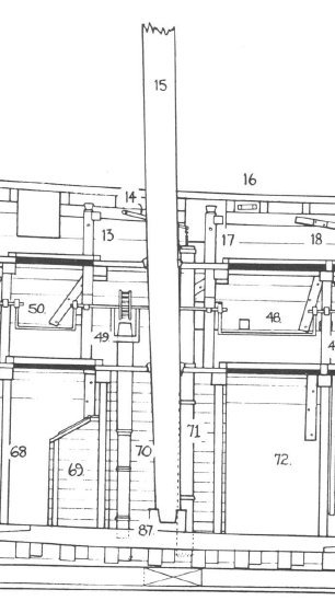
This will be my build log for a project I've been building, on and off for some time. The cross section is of the HMS Blandford, a 20 gun Sixth Rate frigate launched in 1720 and represents a small segment of the ship at the level of the main mast. Included are the mast, the well and shot lockers, chain pump as well as elm tree pump details and weather deck details including 2 cannons. The model will be plank on frame with hull planked down to the wales. There are two decks. As I usually do, I hope to use no paint or stain (or at least as little as I can!). The plans are based on "The 20 Gun Ship Blandford" by Peter Goodwin, one of the AOTS series. The plans were drawn by one of my cyber friends, Mike41 who posts here. He did a great job. Although there are some simplifications in the framing (no chocks or scarfs in the hull frames, for example) the plans are fairly close to the AOTS drawings. The second photo shows the cross section's location in longitudinal view.
- 164 replies
-
- 18
-
-
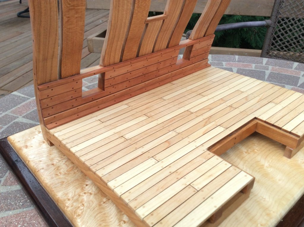
The lower wing assemblies (minus the perforated boards) are complete. Next I need to add two watercourse stanchions to the filling room deck on each side, glue the wings in place and then add the perforated boards.

-
“Independence” seems like a bastardized version of an old “Halifax” kit. The rigging scheme for that ship will work. Daniel Dusek owns the rights to the Mamoli Halifax plans. He will likely allow you to use the rigging and belaying plans non-commercially. He is a sponsor here. PM or email and inquire!
- 122 replies
-
- 2
-
-
- independence
- privateer
- (and 1 more)
-
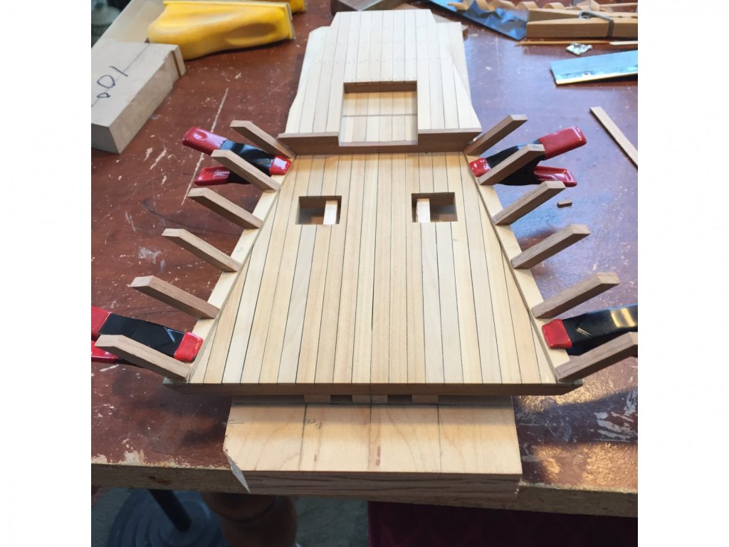
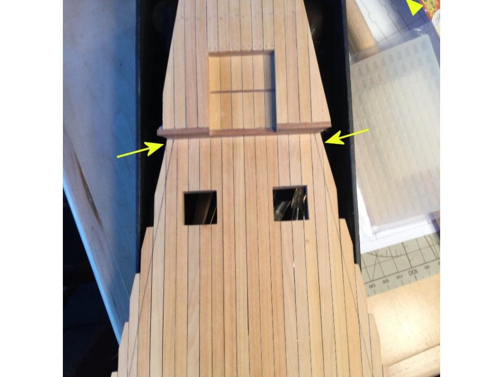
I drew lines on the deck depicting the inboard location of the watercourse chocks. As you can see from photo #1, in the aft most position there is little deck surface for the chocks to grab when glued in place (see arrows). I decided to add a "toe board" of box wood to make assembly and gluing easier. Photo #2 shows the wing assembly under construction.
-
You're probably right! I wasn't thinking of the laser angle cut.
-
Since the laser cut pattern is computer generated and controlled, I would expect that the cut pattern for the port side planking was designed to be the exact mirror image of the starboard. Since both sides of the blank are usable, you could then switch planks around between the sides to camouflage any grain pattern.
-
The grain carrying over from one plank to another is a problem when precutting the planking (laser, CNC). When we designed our 17th Century Battle Station kits, we made sure to randomize the planking (especially the decking) to get a random look and avoid the grain continuing from one plank to the adjacent ones. Of course we were only producing 3 kits! Doing this in a commercial venture is probably not cost effective.
-
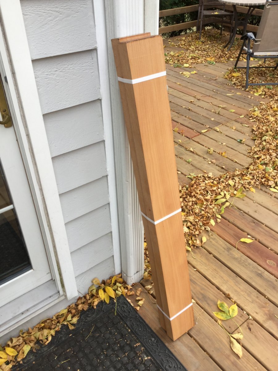
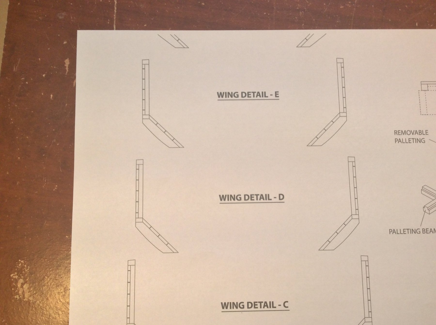
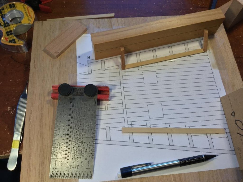
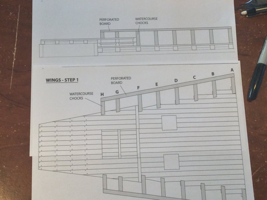
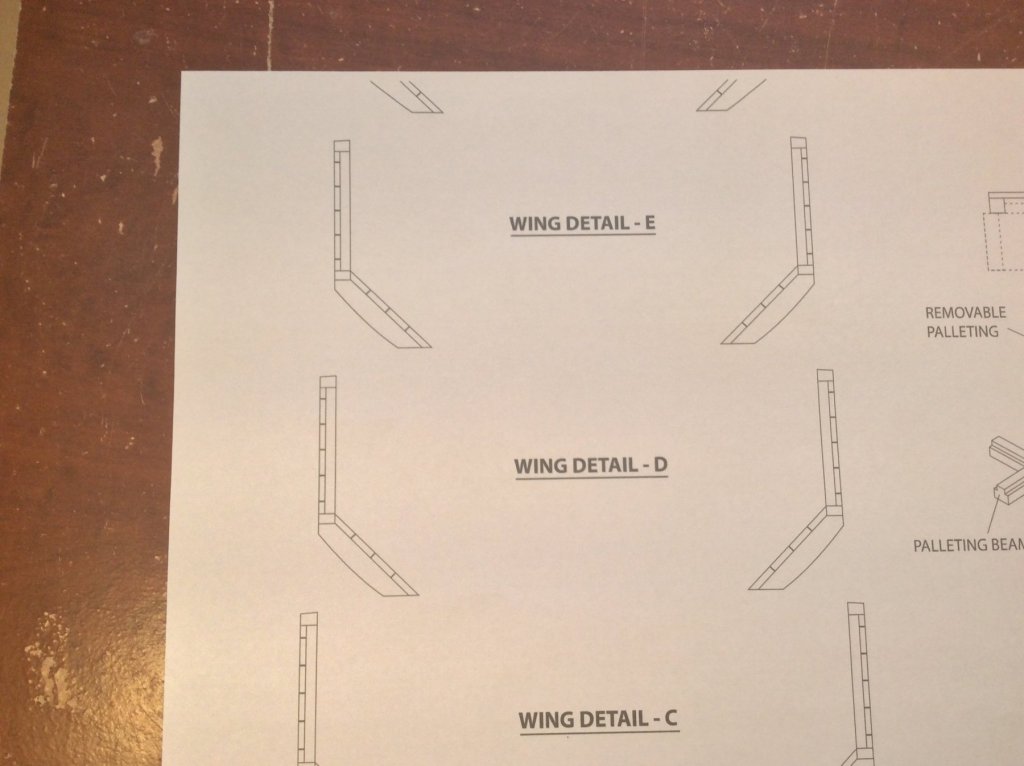
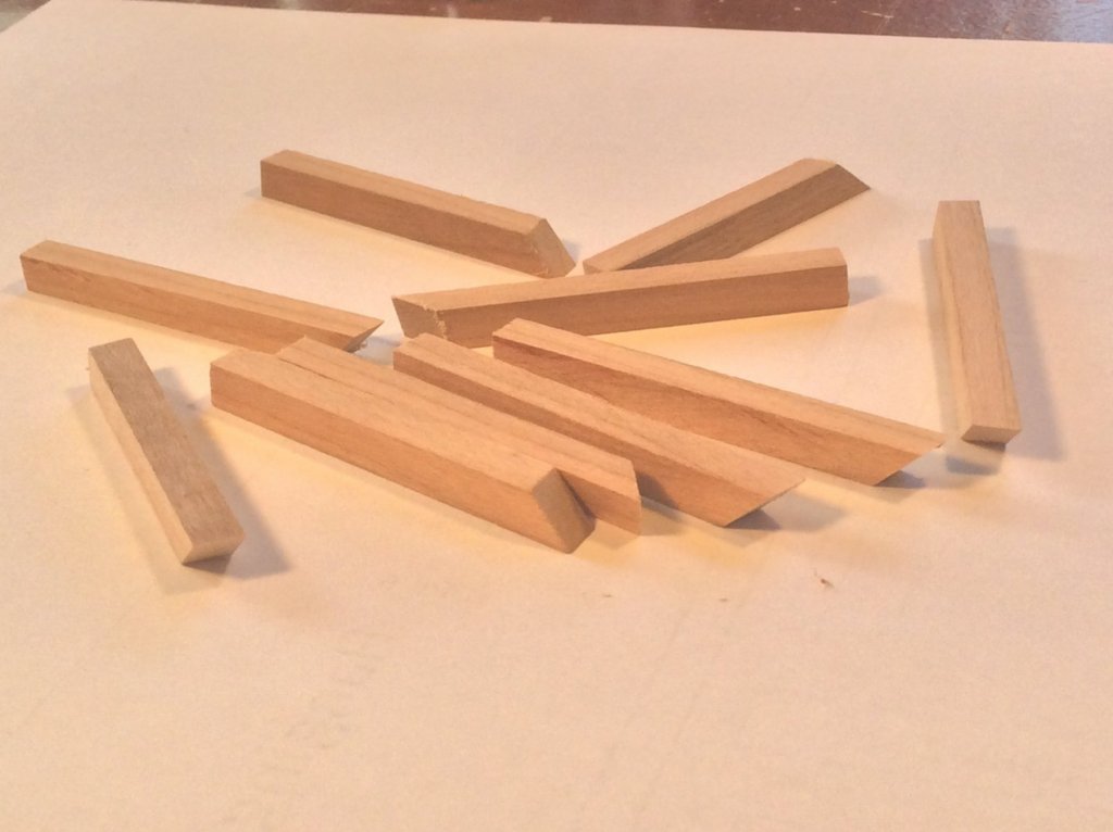
The "wings" form the side walls to the powder room and the filling room. They are constructed by fabricating stanchions known as "watercourse chocks" which are then planked over. They arise from the deck at a 45 degree angle and angled 10 degrees from the centerline of the ship. These wings will be the toughest part of this build by far. They are topped with the perforating board, and from there the sidewalls go straight up. The first picture shows a plan view and longitudinal view of the chocks. The second photo is cross sections of the wing at a few levels. The last photo is some blanks, cut at 45 degrees and 10 degrees to form the compound angle. Next up it to build a jig so I can uniformly cut the top of the watercourse chocks correctly.
-
Can i live without a BYRNES TABLE SAW
DocBlake replied to shihawk's topic in Modeling tools and Workshop Equipment
You won't regret it! The only thing that could make the Byrnes saw better is Jim using his precision machining skills to create a tilting arbor for angle cuts. There is a tilt table available, but is fussy to use and time consuming to set up. I guess you can't have everything. Also, here's a link to the Byrnes saw user guide mentioned above: http://web.archive.org/web/20160401201451/http://www.hobbymillusa.com/byrnes-saw-operation.php -
Very interesting! I'll be watching this one. I'm also awaiting Master Korabel's tender "Avos".
- 40 replies
-
- 3
-
-
- finished
- master korabel
- (and 2 more)
-
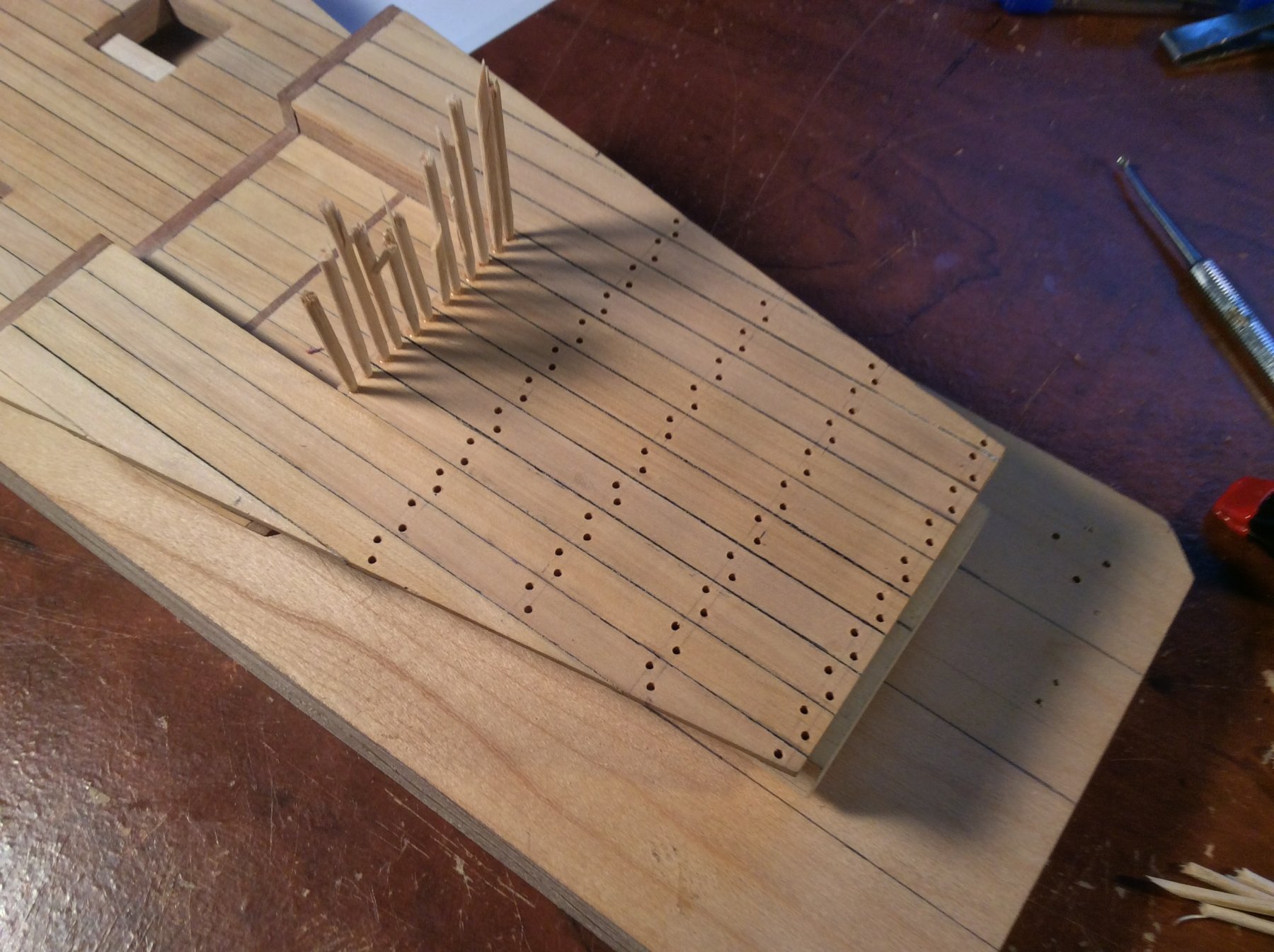
Thanks for all the "likes" guys! After the planking was completed, I began to treenail. Much of the planking will be hidden or obscured, so only the most aft portion of the magazine (the light room) will get treenails. I used a #58 drill and toothpicks glued with CA. Next up is the most difficult and challenging part of the build: Laying out, constructing and planking the wings which will form the side walls of the powder room and filling room. This is going to take a while!


-
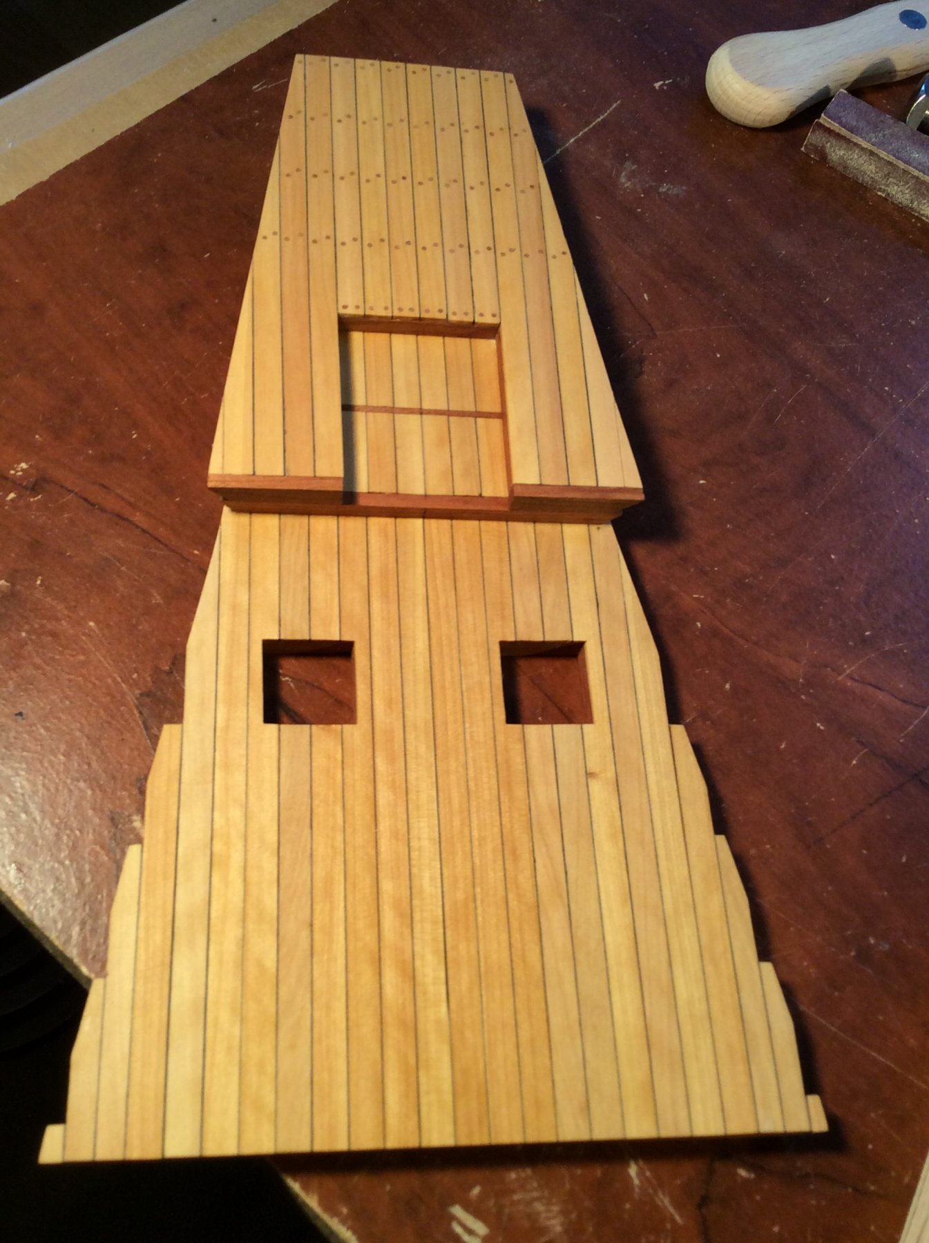
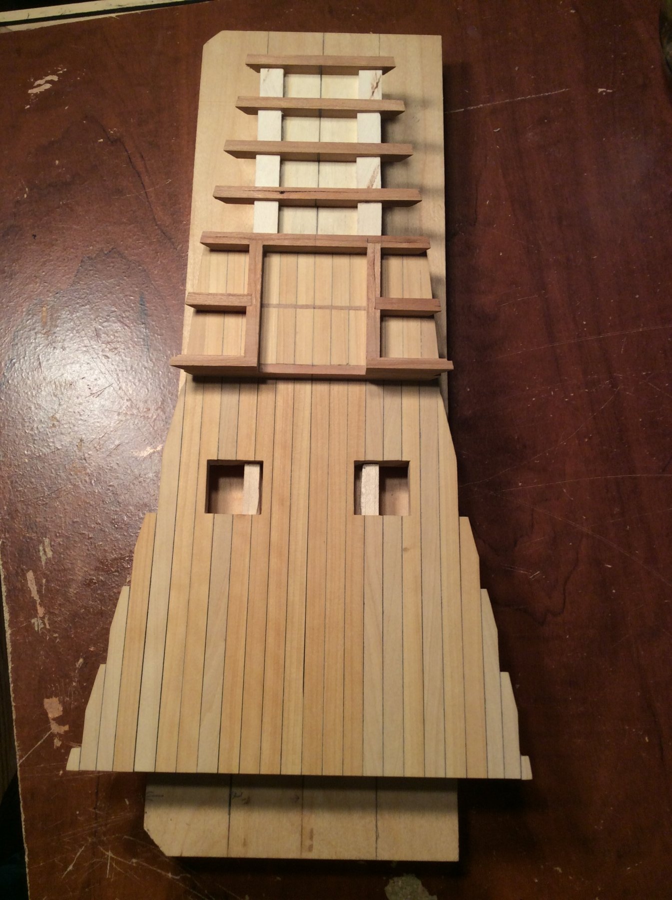
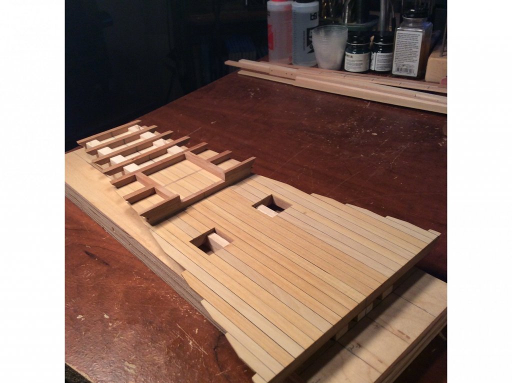
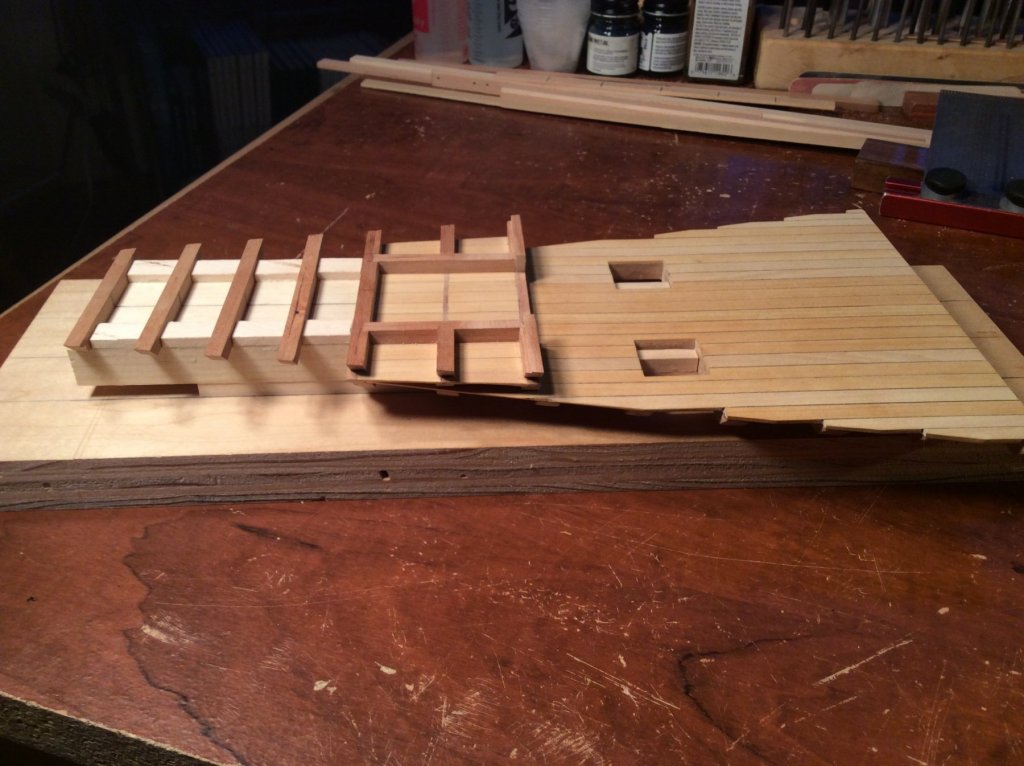
Thanks for the "likes" everyone! The final step in completing the decking for the magazine begins with framing the light room and filling room floors. I then used boxwood planking for the deck. I need to add some treenails and when that is complete, I'll start on the powder room walls and palleting.


-
Great job of rigging, Bob. You are a master - I muddle through! Very nicely done.
- 359 replies
-
- 4
-
-
- prince de neufchatel
- model shipways
- (and 1 more)
-
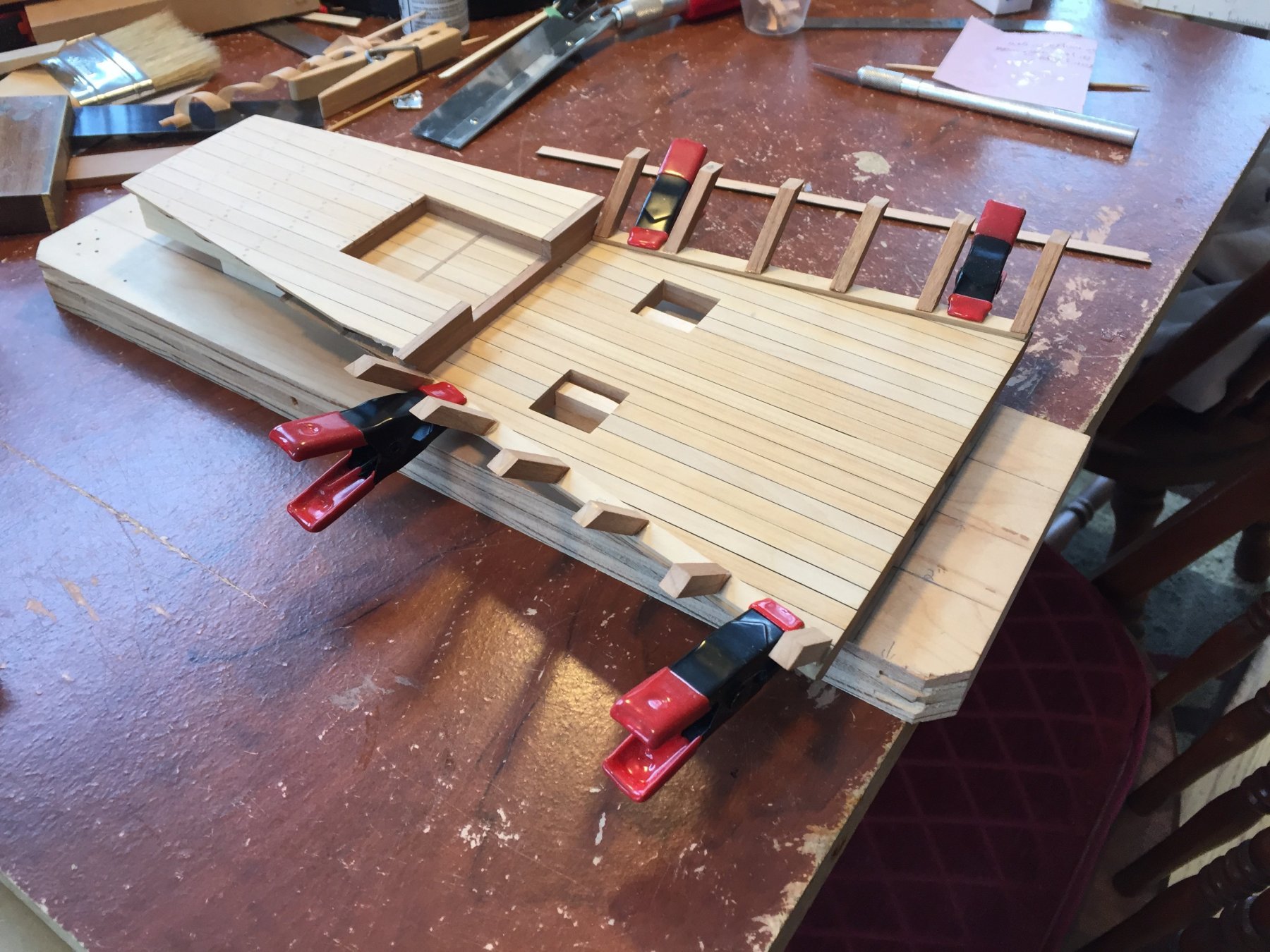
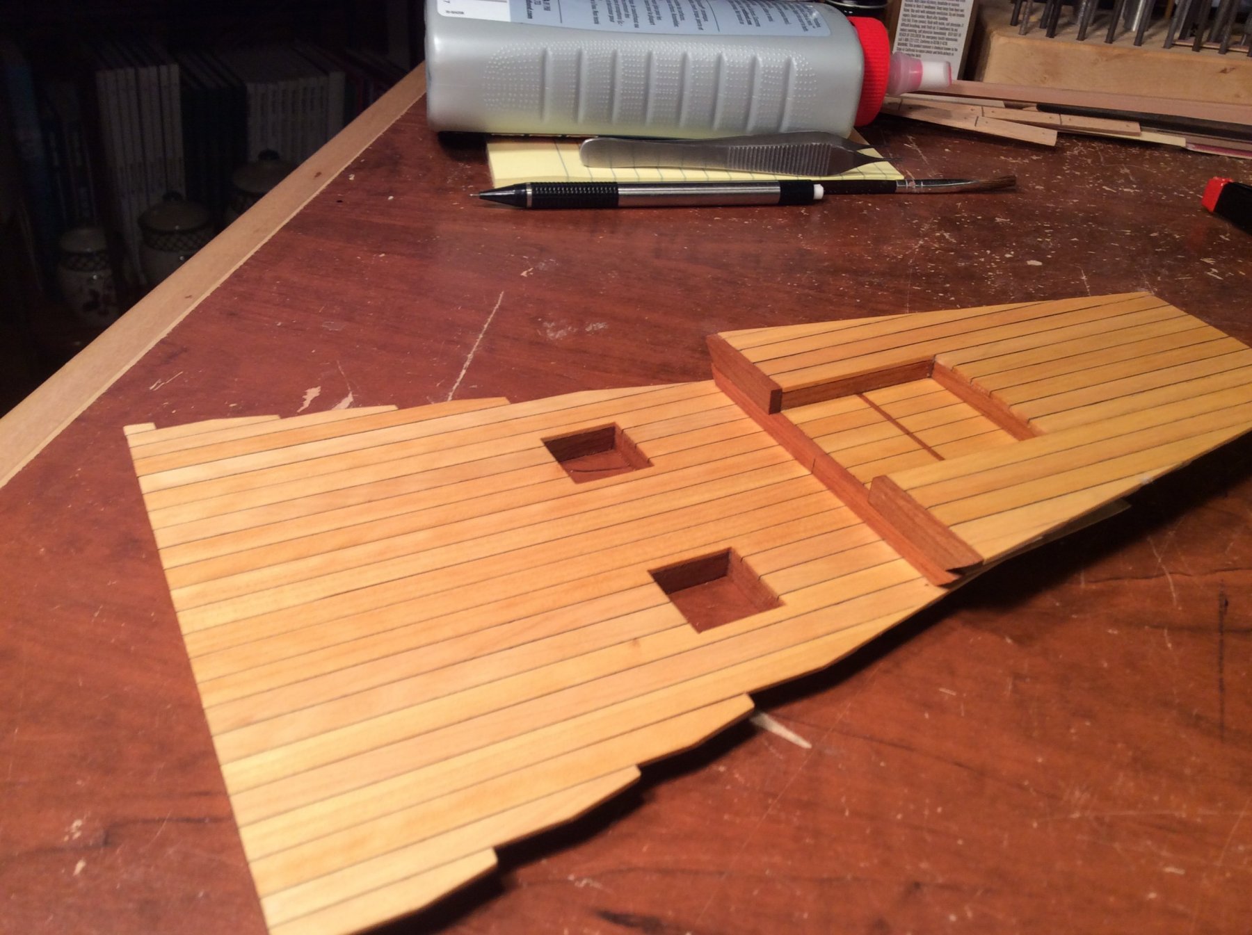
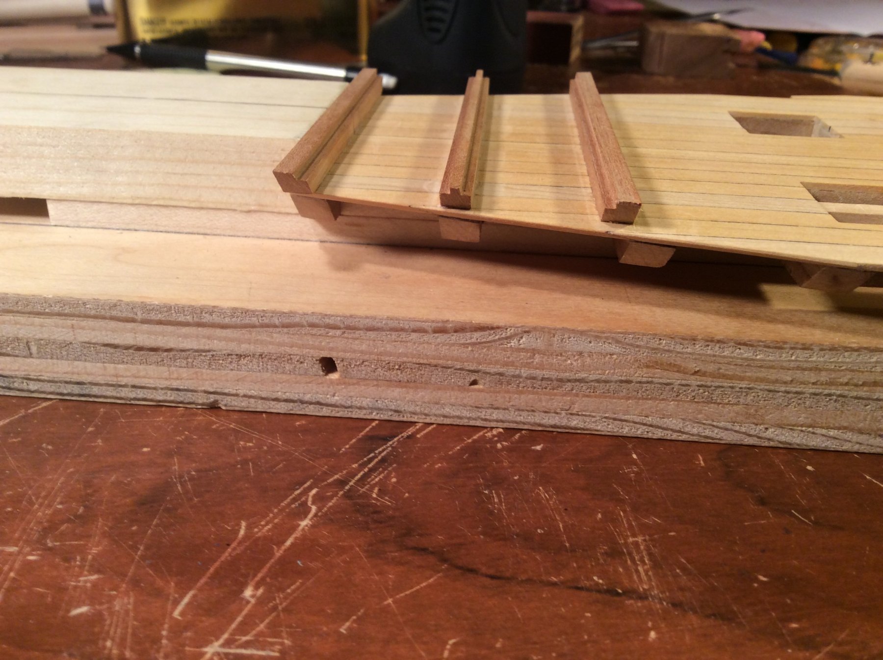
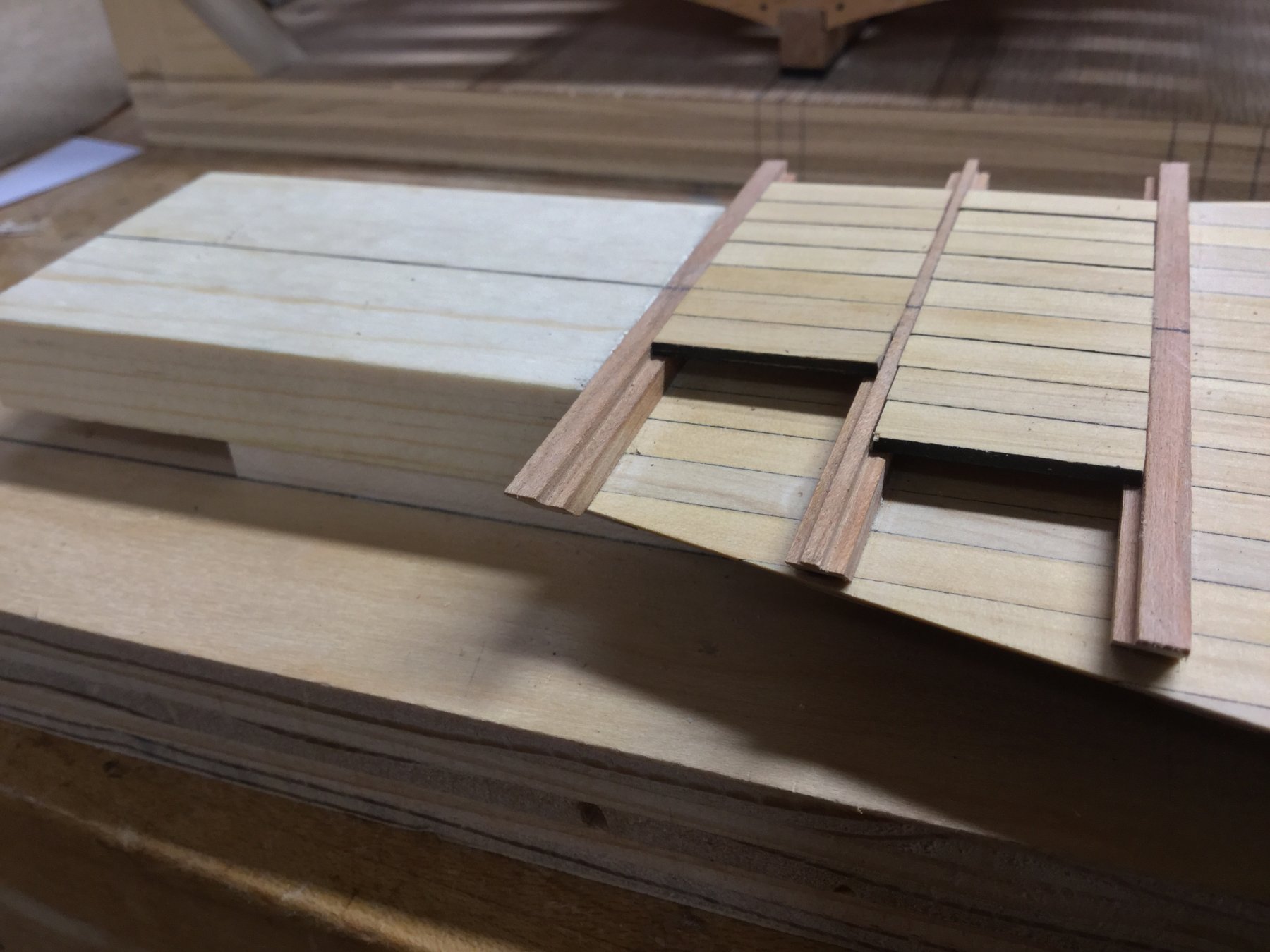
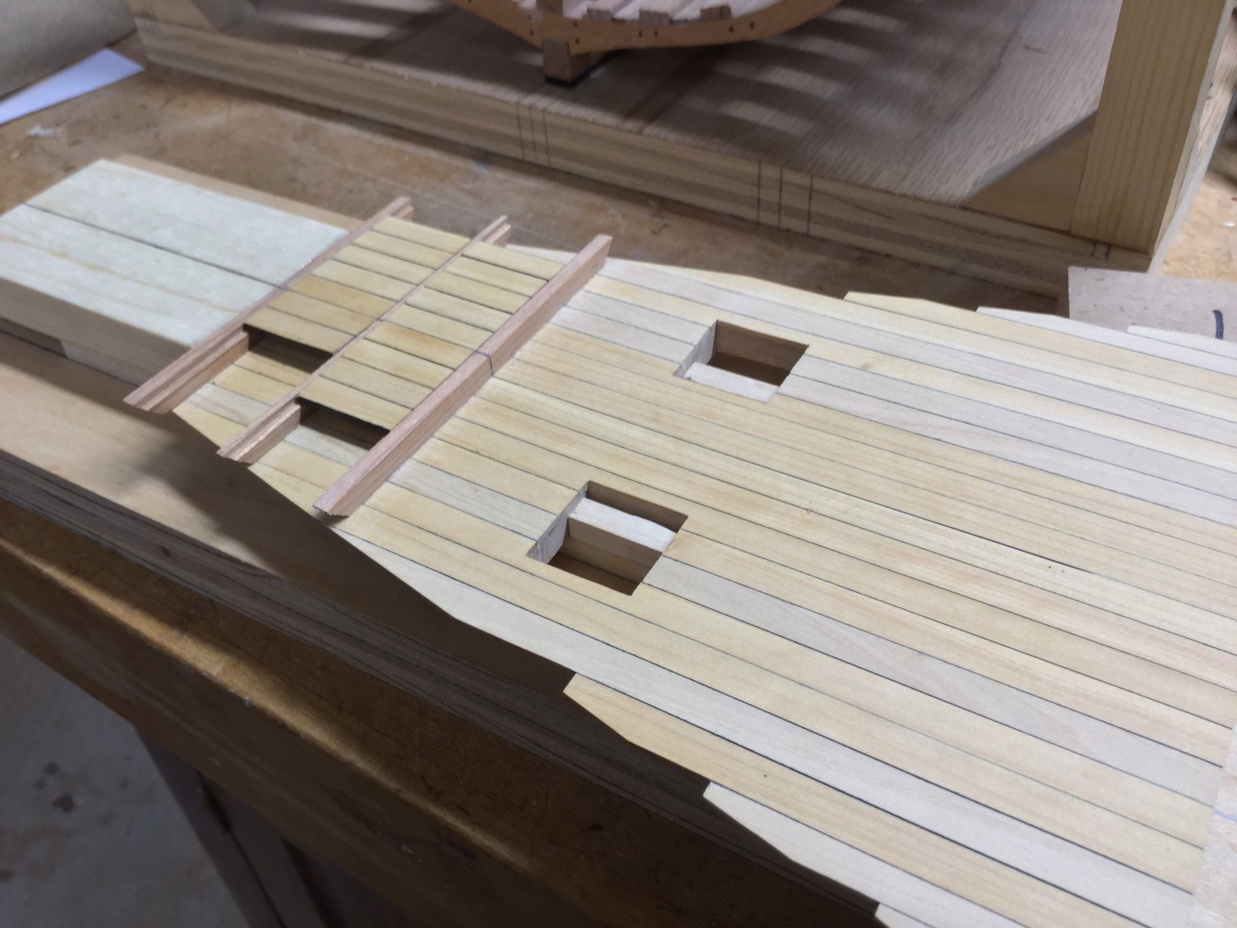
The filling room deck is supported by 3 beams, each 3/16" square. The planking is set into rabbets cut into the beams.


-
Thanks, guys! And thanks for the "Likes".
-
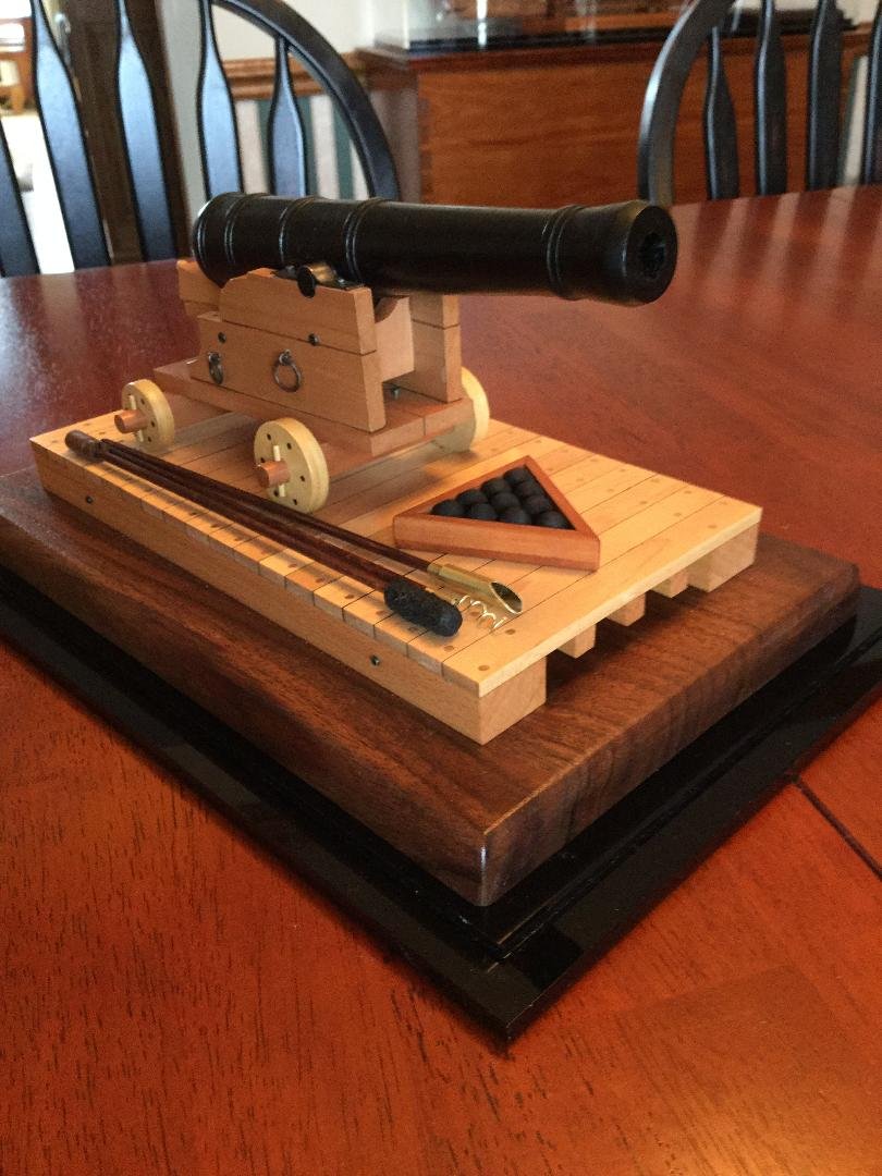
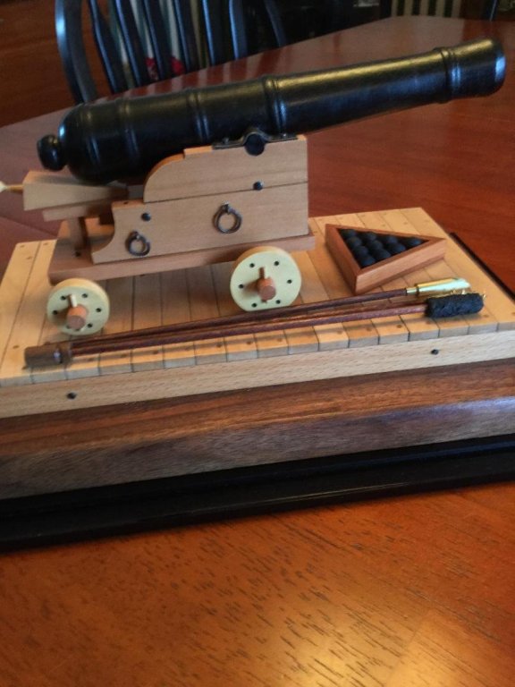
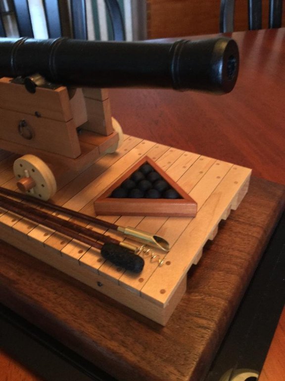
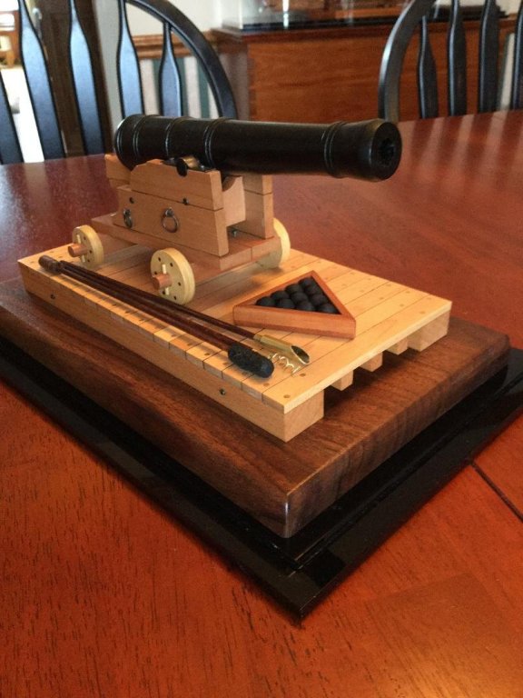
I thought I was done with this project, but looking at the gun sitting all by itself made me feel something was missing. So I added a few tools! First was the triangular shot rack, with cannonballs sized for the 3/8" bore of this 9 pounder. Next was the powder ladle. I used brass tubing to make that. The worm was made of brass wire, but if you look closely, you'll see I cheated! Normally the worm had a double helix on the end. I just left it single. The last tool is a combined rammer (small piece of shaped walnut) and the sponge. The sponge was made by coating a piece of dowel in glue, then rolling it in sawdust. When dry, I painted it flat black.
-
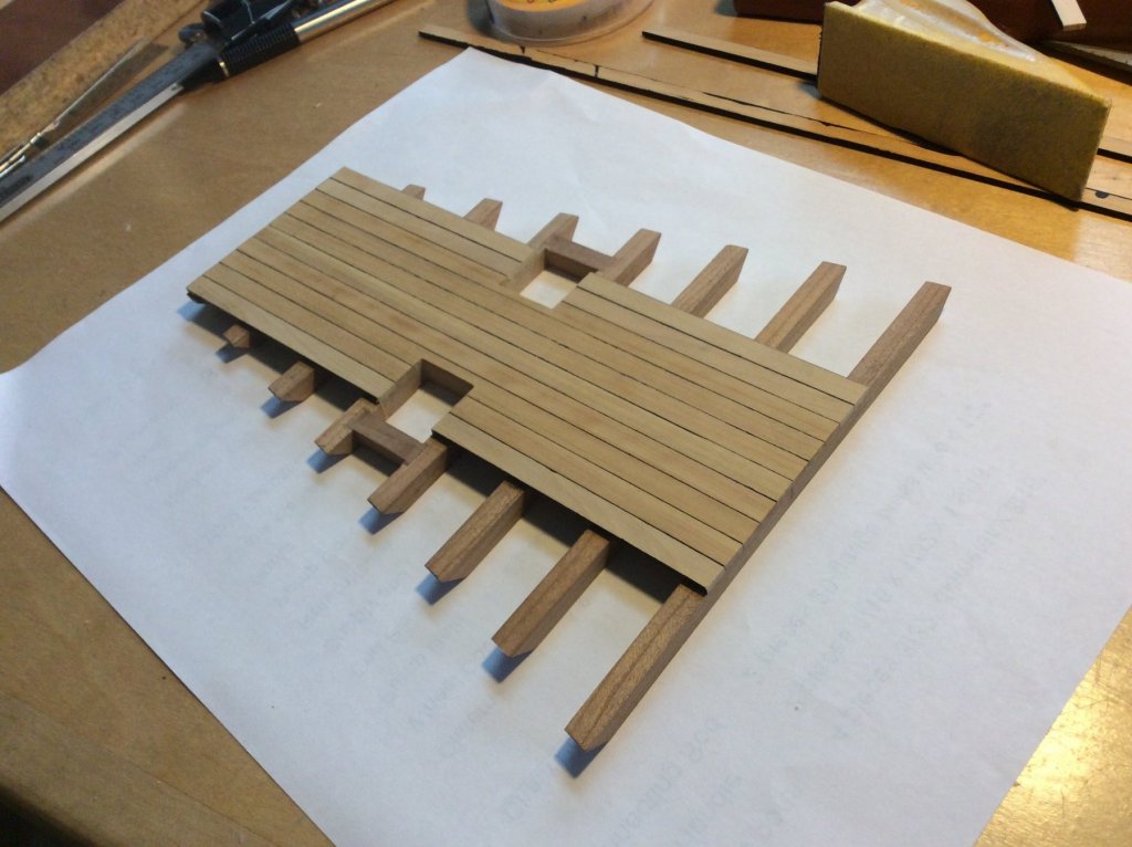
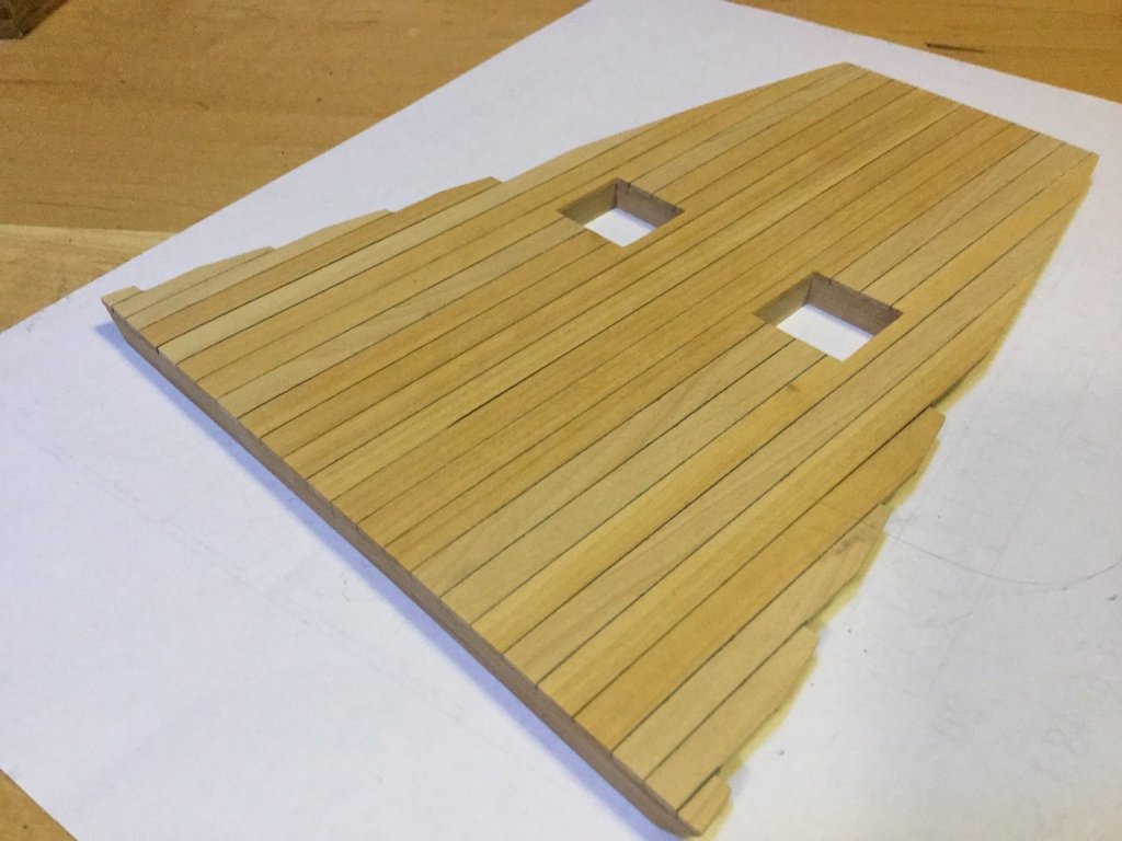
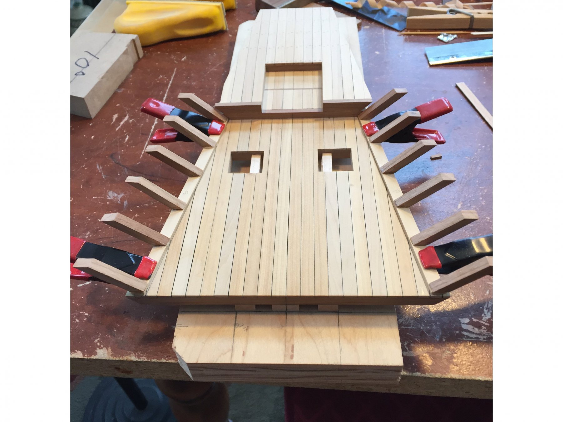
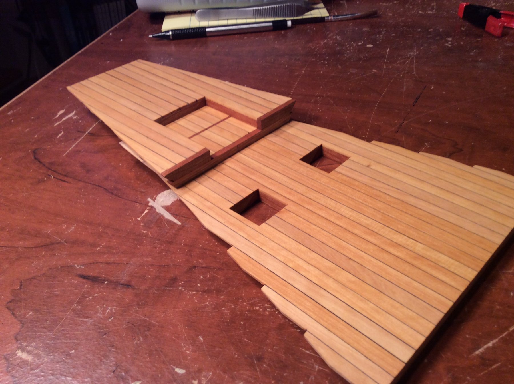
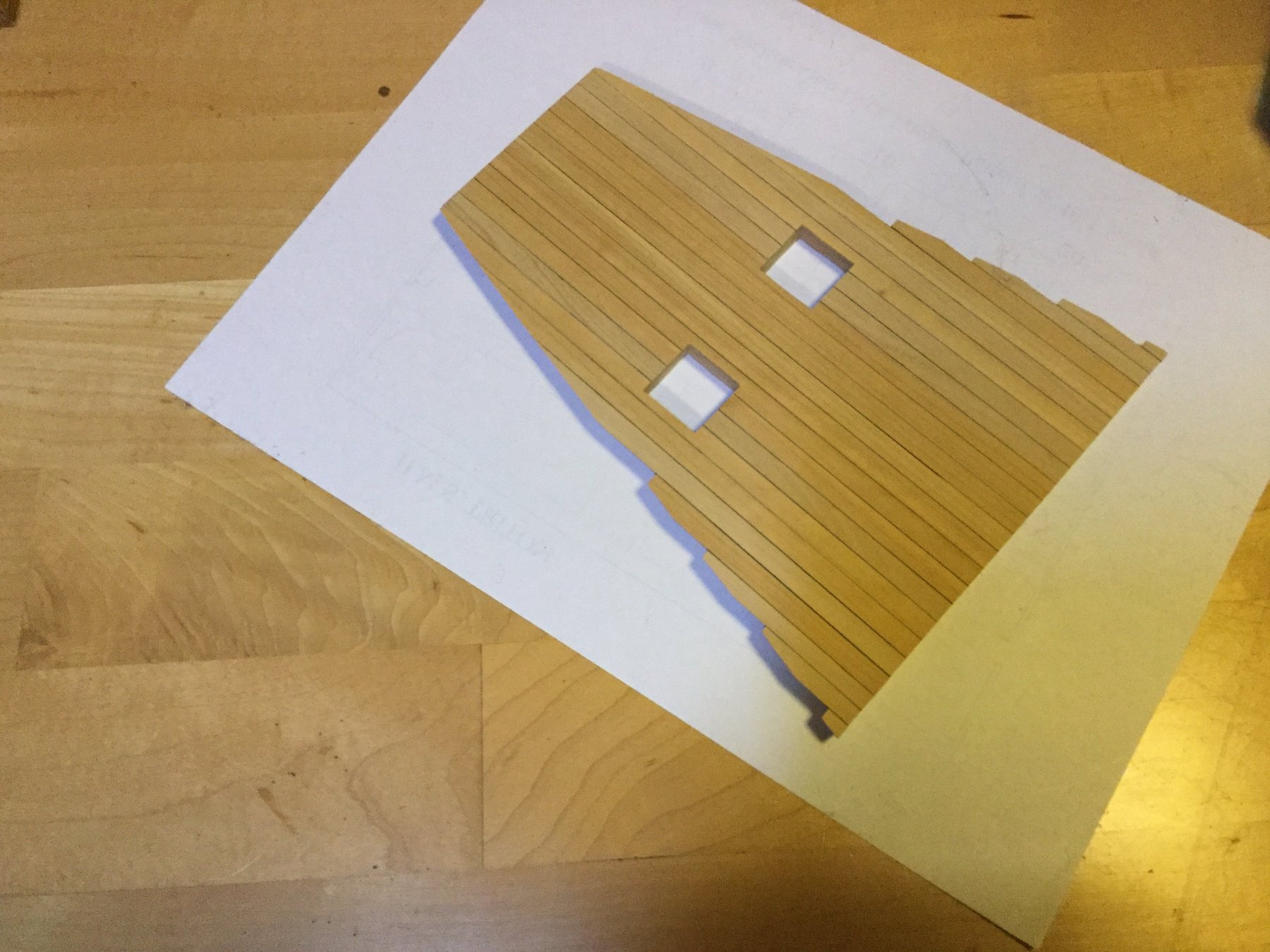
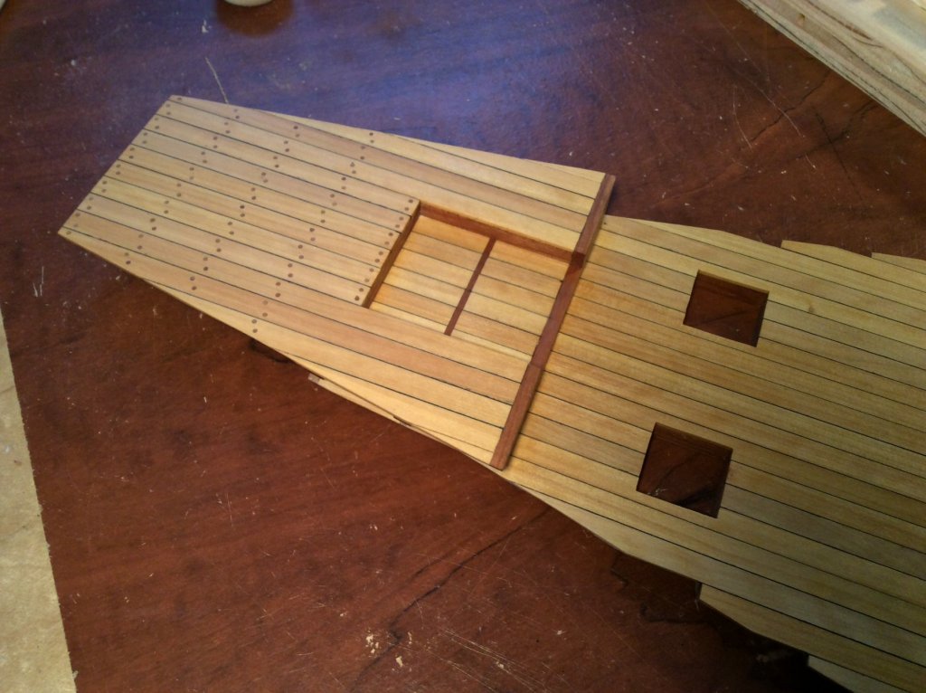
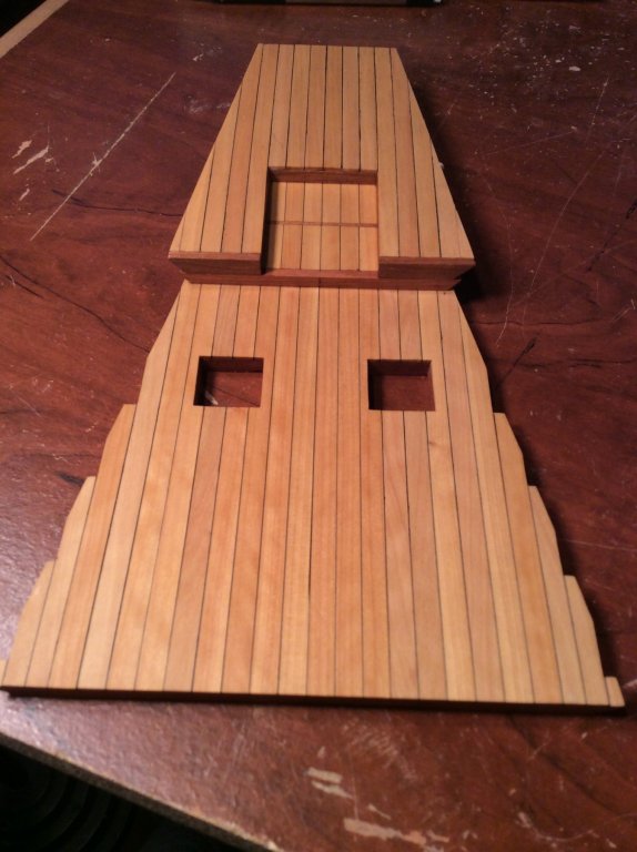
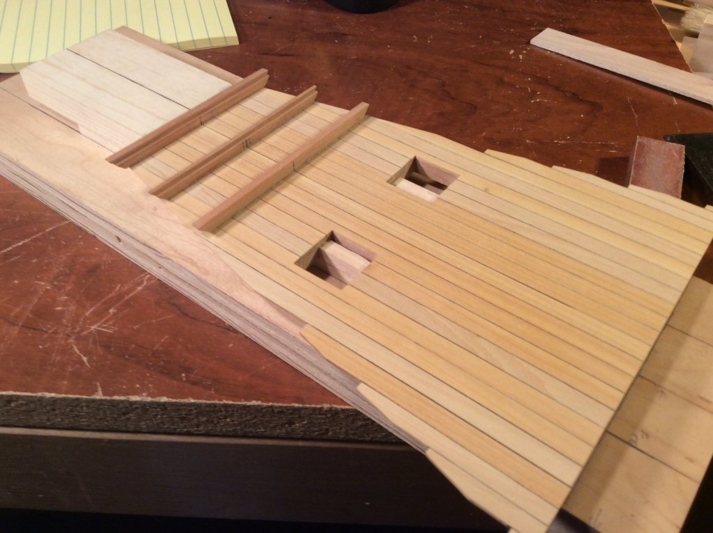
I began planking the magazine deck with 1/4" X 5/64" boxwood planking. This translates to 8" in scale width. The planking will be treenailed. I use a paint pen to paint the edges of the planking black. Any excess scrapes off easily with an X-Acto knife. Since this is a magazine, no iron or steel was used for anything -including fasteners- because of the danger of sparks igniting the gunpowder. All metalwork would be copper. The decking for the magazine is on several levels, each supported by it's own set of beams. The main powder room (where the two scuttles are) will have palleting on the deck, set into rabbets in the framing.