DocBlake
-
Posts
1,811 -
Joined
-
Last visited
Content Type
Profiles
Forums
Gallery
Events
Everything posted by DocBlake
-

Brig Eagle by robnbill - 1:48
DocBlake replied to robnbill's topic in - Build logs for subjects built 1801 - 1850
Excellent work so far. Very nice job, Bill. Looking forward to more. Dave -
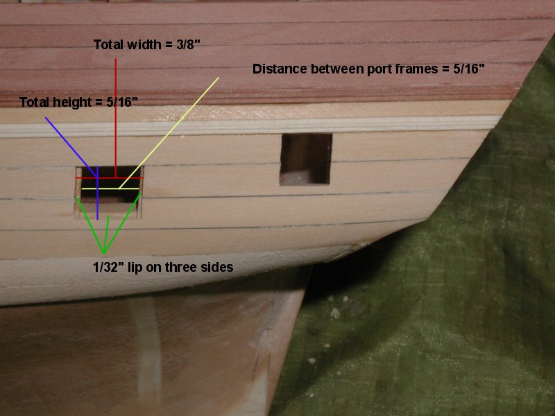
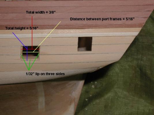
Jon: I know what you mean about pitfalls. At least half of those I encounter, I created myself! I do like the way the transom turned out. As I start framing the gun ports, I decided to switch from boxwood to swiss pear, so the framing and sills match the inboard bulwark planking. I'd like your input on this, please. I'm ready to begin framing the gun ports. On each side, the first two ports from the bow, and the last two near the stern have port lids, so a lip has to be built to give them a surface to close against. The middle 12 ports (6 on each side) have no lids.I want to make sure my measurements are correct, because I got a little confused by the practicum which talks about a 1/64" lip, but gives measurements for the sills that result in a 1/32" lip. The non-lidded ports are 3/8" wide by 5/16" high, lined with sills and framing. The ports with lids have the same size opening in the external planking, 3/8" by 5/16", but have a lip on three sides formed by moving the side framing in 1/32" on each side leaving the side lips, and gluing the lower sill 1/32" above the bottom of the opening to give the lower 1/32" lip. Does that sound right? Here's a photo: Dave
-
Weatim: Go to lauckstreetshipyards.com and look under "services". You'll see a tab for downloads. Click on it. There are a series of sample chapters for several Bob Hunt practicums (really "practica"!). They are each Chapter 1 for each particular ship. Download one. Each sample chapter 1 has a list of tools and supplies useful in ship building. You won't need them all, but It'll give you an idea of what to purchase. Dave
-
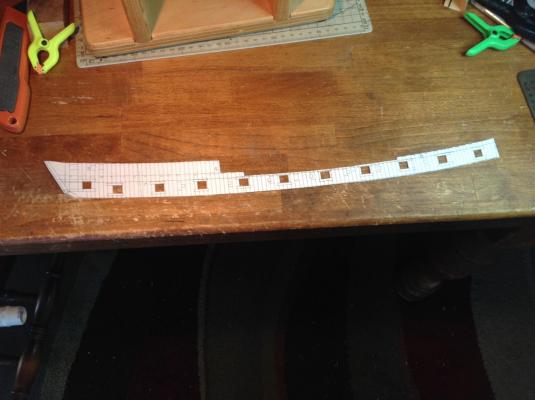
Thanks, Mark. You're right that the template is only really useful amidships. I plan to establish the bottom of the ports in that area and use the measurement from the deck to the port opening bottom to establish the proper location for the fore and aft port bottoms. Their fore and aft locations are easy to measure from the amidships ports. Dave
-
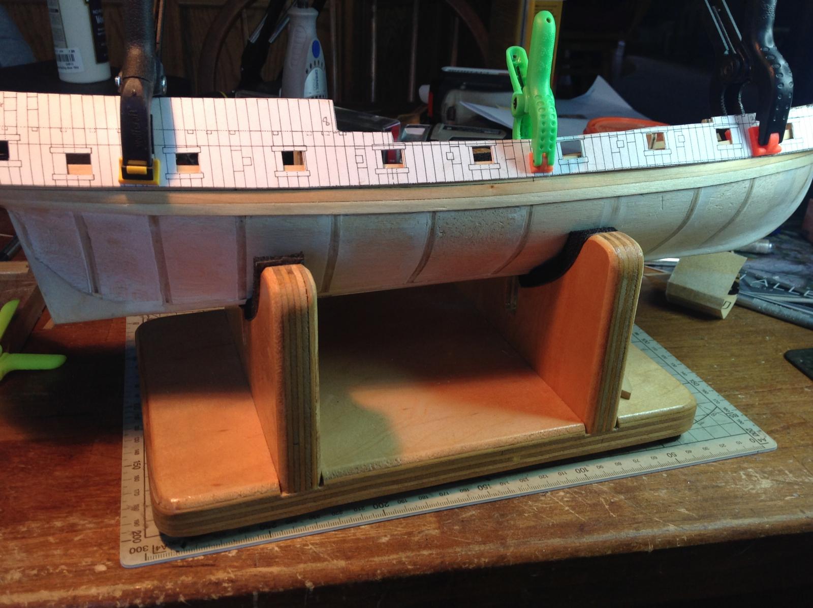
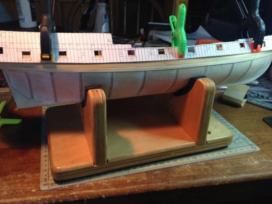
The wales were established by cutting out a copy of the Hahn plans along the wale sheer line, and marking the location on the hull. The was the upper border of the wales. A plank was laid along the line, and a second plank below it. I then planked two strakes above the wales. Two additional planks of ebony will be added to the wale planks to give them their thickness. I then took the copy of the wale sheer from Hahn's plans (mounted on cardboard) and cut out the gun ports. The template was then used to mark the gun port locations on the model. The ports will be cut out and framed next. Dave

-
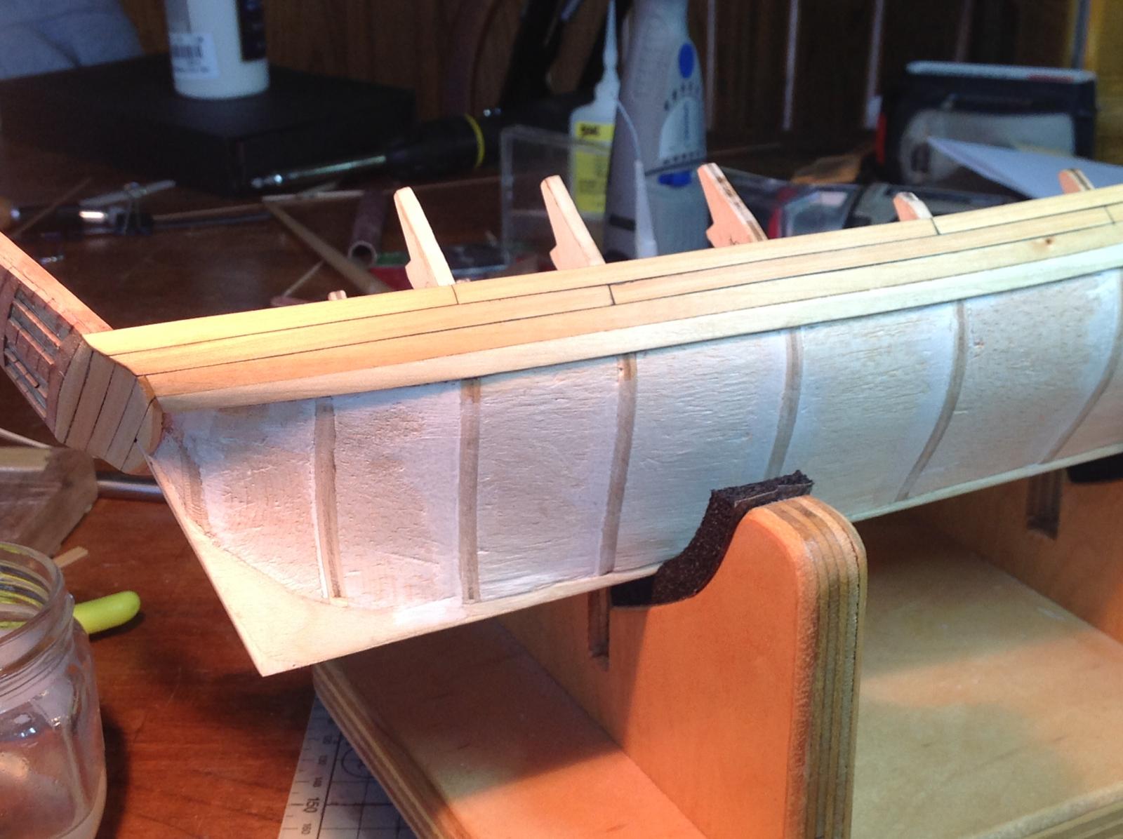
All totaled, I broke the transom, either partially or completely, from the hull 3 times. This is because it is flimsy and fragile with a minimal glue line holding it in place at a bad angle. It's always in the way! I decided to plank the counter and the transom first, which I did. This stiffened the transom and provided more attachment area to the hull. it is much stronger now. The outer bulwark planking is done to the second plank row. Next up is cutting and framing the gun ports. Dave
-
I've been using Weldbond for a lot of applications, but as a woodworker I know PVA glues are the best for wood to wood joints. Weldbond has an initial fast tack, which I like. I've heard a number of negatives about it, though. TiteBond makes a glue called No-Run No-Drip, which used to be called" Molding and Trim" glue. It is a PVA that has an initial fast tack. Anyone with experience or comments on this glue for model ship building? Dave
-
Jon: "Ouch" for sure...but it's only wood. The fix ate up a day, but beyond that, not that big a deal. I think I'm learning a few things! Dave
-
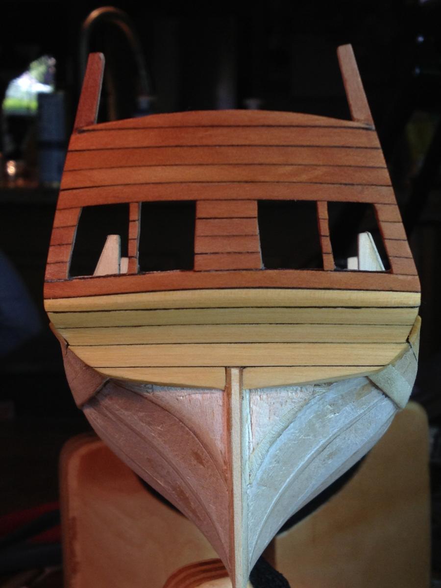
I cut a new timber and patched the 1/32" plywood in, repairing the damaged transom. After it's planked no one will know anything happened. Dave

-
The transom on this model is jinxed! Every build log reports trouble at this point. I thought I was cruising along, having attached the transom and determining that the stern post fit and that there was room for the rudder post to pass through the cabin up to the deck. I then planked the counter, and when I finished I discovered that the transom was not in one plane perpendicular to the keel. The starboard side leaned back too far. There was some give in the transom, so I foolishly thought I could pull it back to square with a rubber band. The rubber band was too tight and snapped off one of the timbers along with some of the 1/32" plywood. Of course the part went flying, and it went to that special place where all parts dropped on the floor go to, never to be seen again! (plenty of unmatched socks there too!). I'm going to have to rebuild the transom. Oh well.... Dave

-
I like the white frames also. Can't wait to see how it looks when finished. I have the AL "Bounty" on the shelf also. Dave
-
Hi Jonathan! I haven't used ebony in this way either. The Wood Database suggests it is amenable to steam bending, which is what I plan to do...using a plain old clothes iron! BTW, my counter has 4-1/3 planks, compared to yours which had 4. I also had to rework the angle of the stern on the false keel to keep the relationship between it and the planking the way the practicum suggests. One question: How did you glue the transom on with only those tiny frame ends supporting it and functioning as a gluing surface? Dave
-
I put the Rattler on hold as I finished up my "Swift". Now that she is done, it's back to it. I installed the first layers of the double-planked wales. This is basswood and helps define the counter. It will be covered in ebony. After the wales were defined, it was obvious I needed to clean up the fairing at the stern, which I did. I've not installed the transom yet, because I was concerned I'd break it off while planking the wales. Next up is planking above the wales, and constructing gunports Dave


-
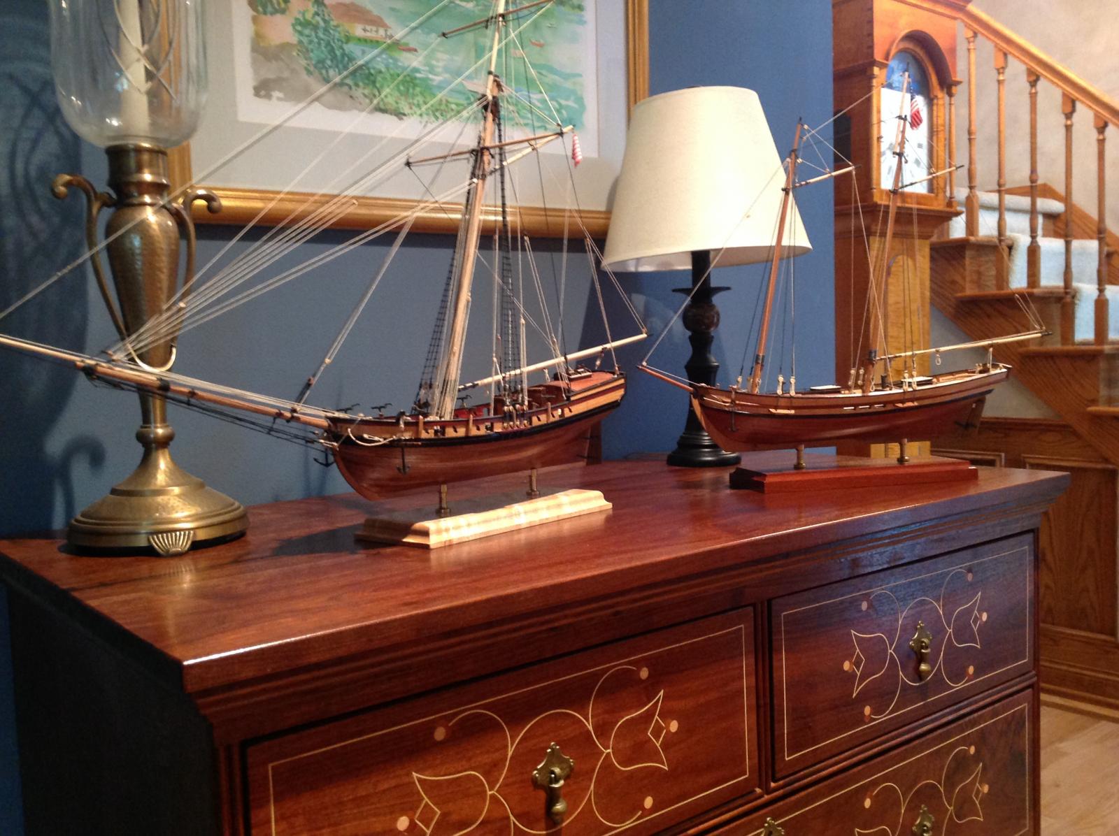
Speaking of collections, here's a shot of the Virginia pilot boat "Swift" and my "Armed Virginia Sloop" in their temporary home...our version of "Norfolk Harbor"! Dave

- 11 replies
-
- 1
-

-
- swift
- artesania latina
- (and 1 more)
-
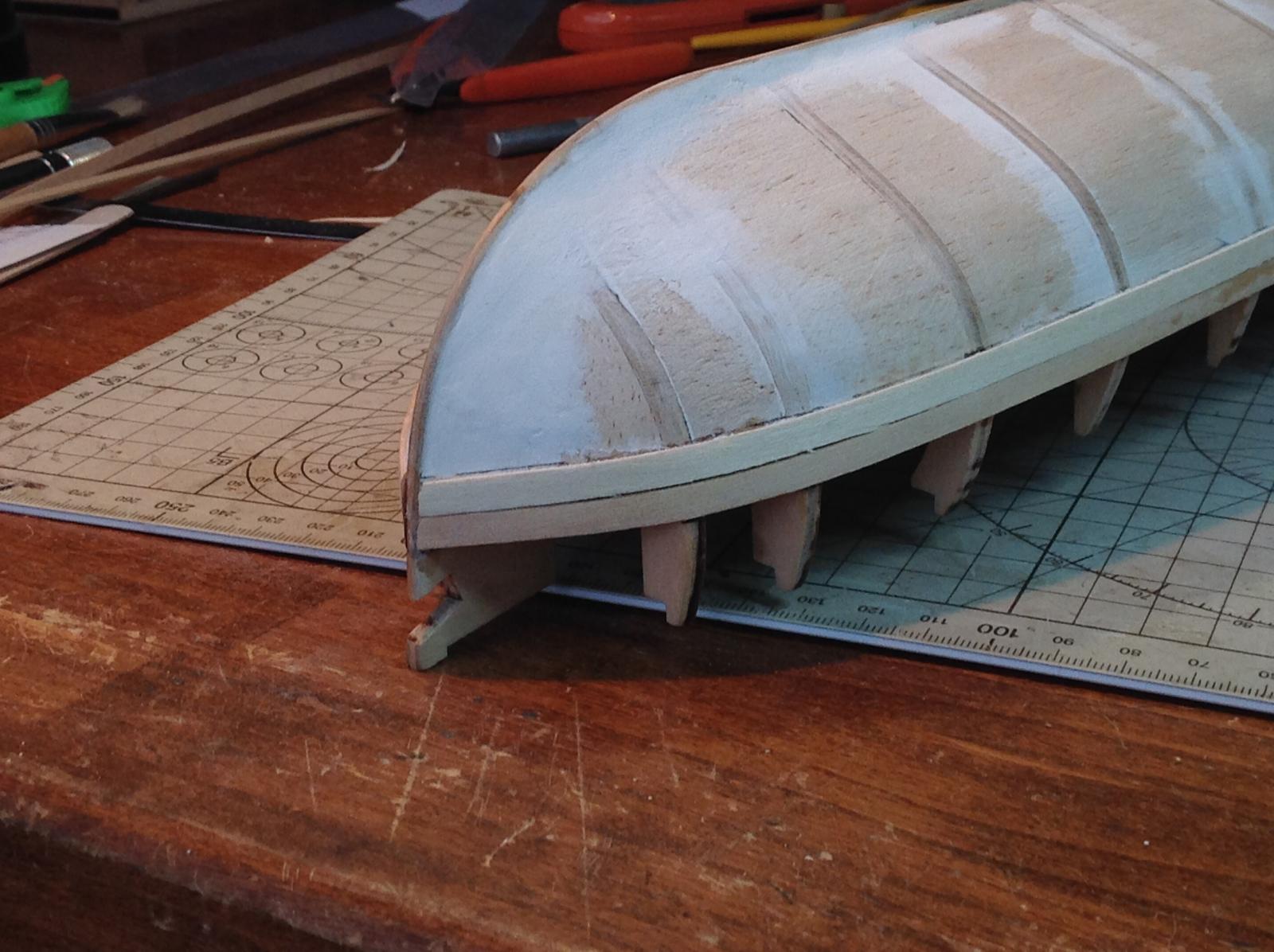
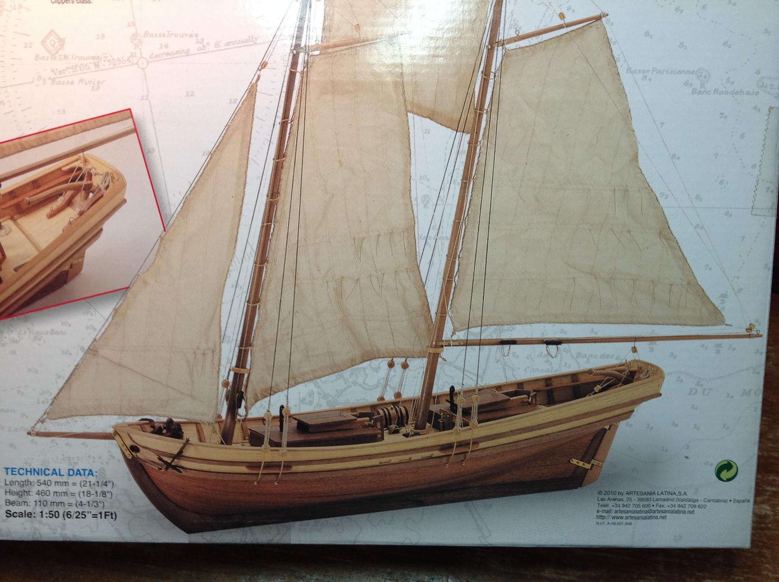
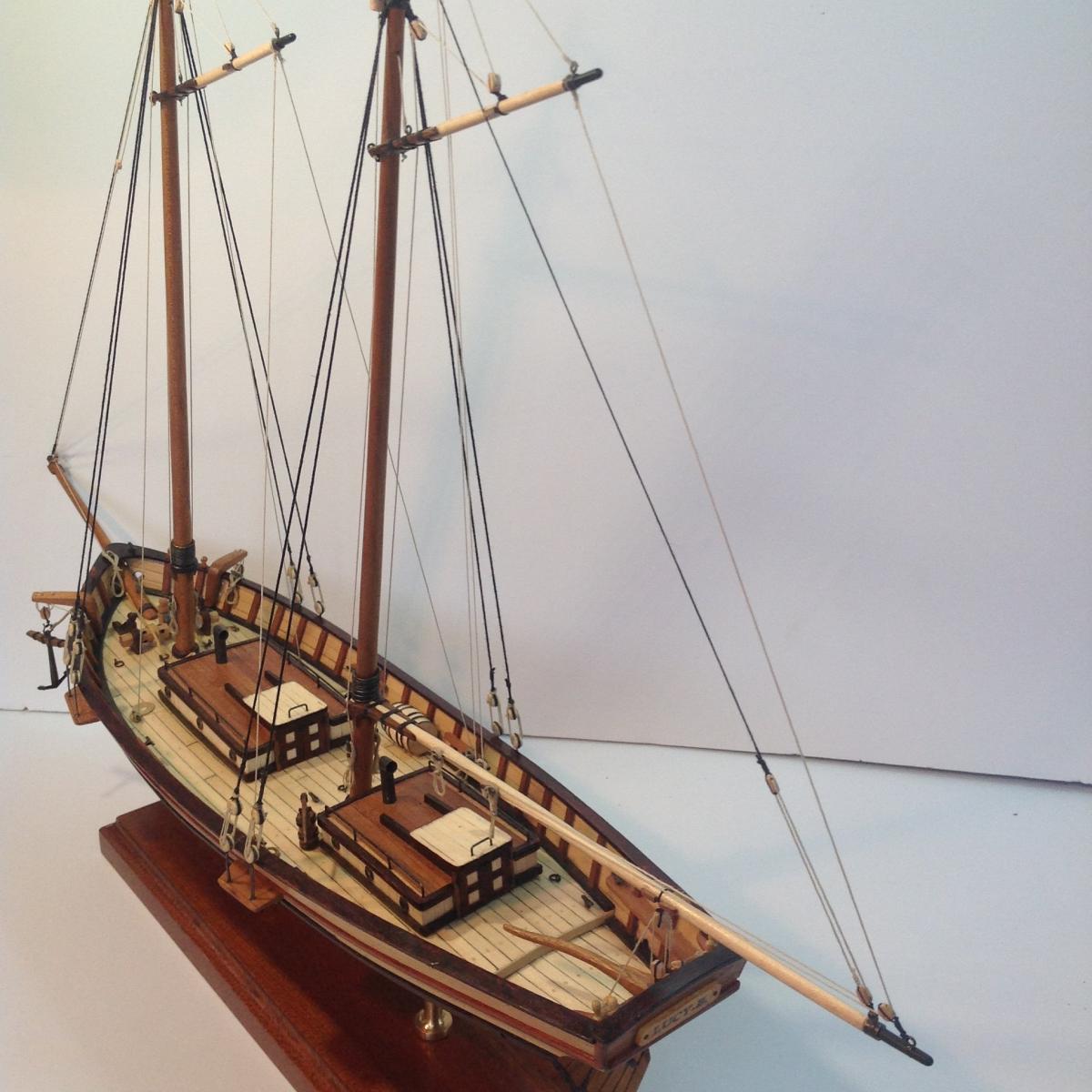
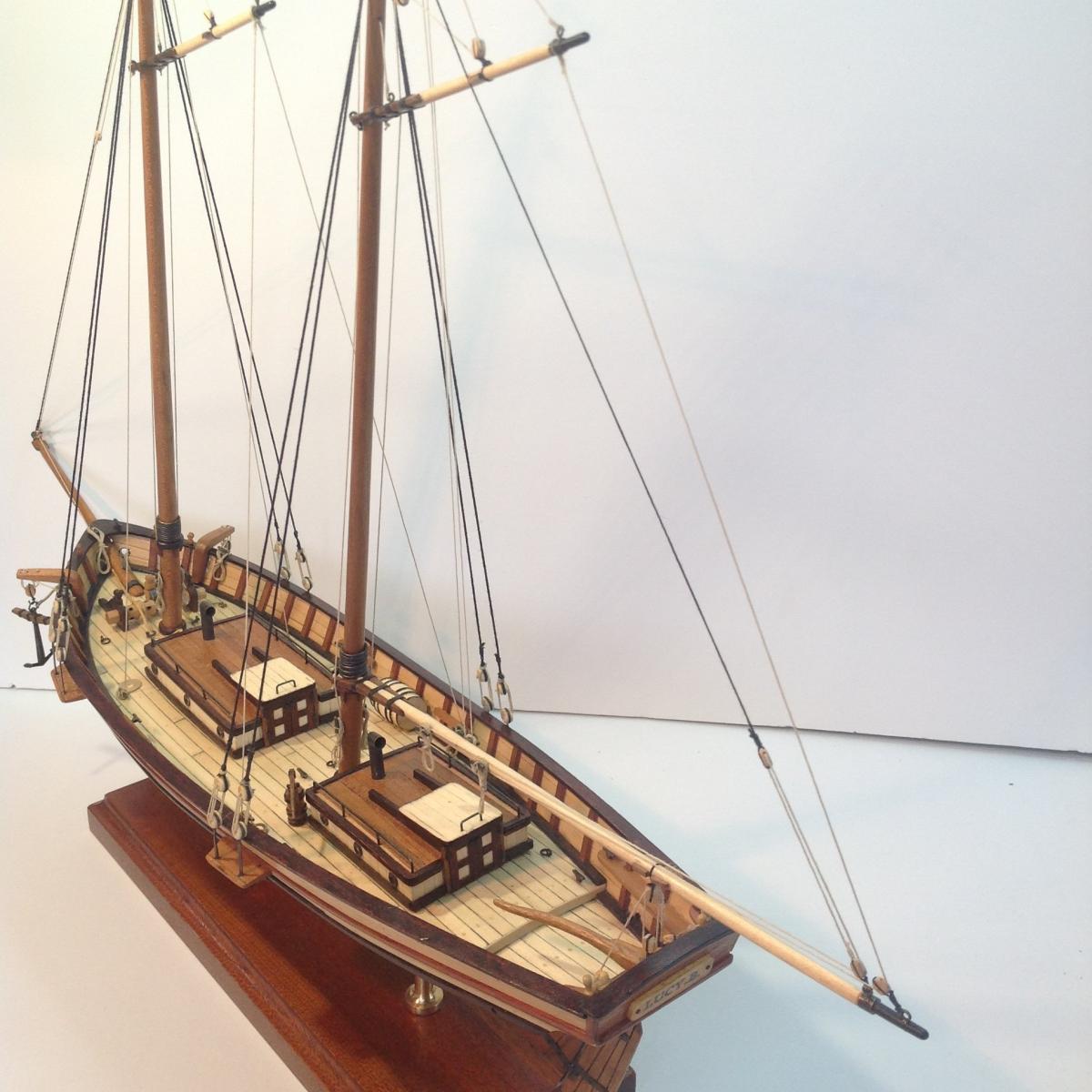
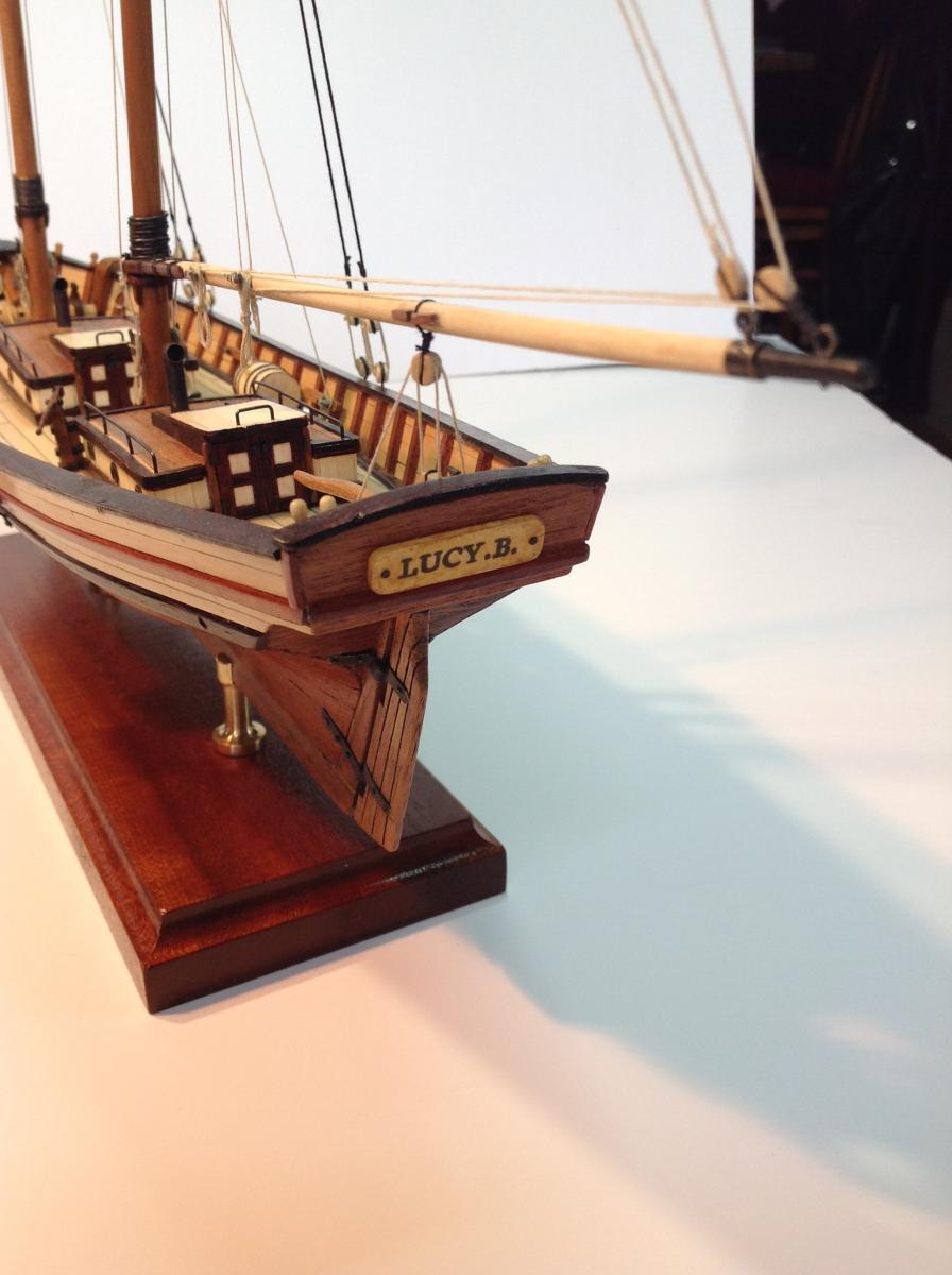
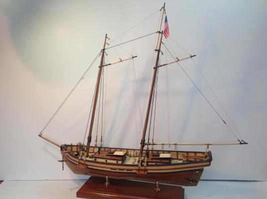
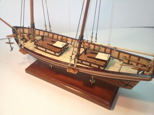
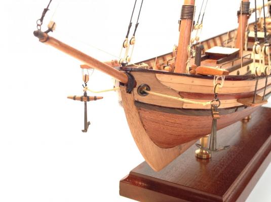
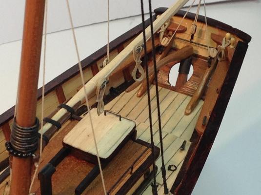
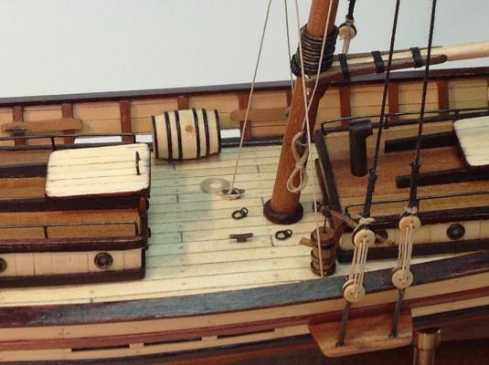
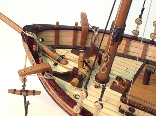
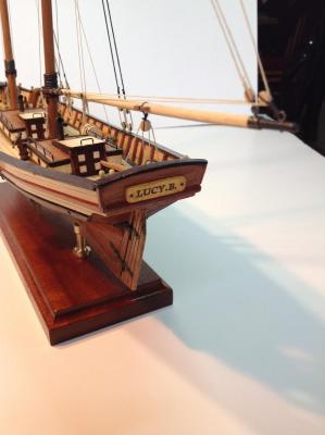
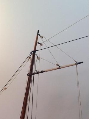
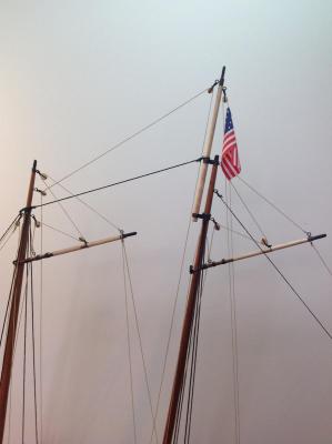
I finally finished "Swift". I renamed her "Lucy.B." after our beloved golden retriever (my AVS was named after my wife!). I made a lot of changes to the stock kit. I've enclosed photos of the build, as well as a shot of the stock kit box to point out the differences. Here's a list of the changes I made: - Switched out wood, using boxwood, cherry, rosewood, maple and blood wood. - Eliminated the bitt over the bowsprit - Fitted the sprit to the deck with a metal bracket (more authentic) - Gammoned the sprit to the stem - Added knightheads and catheads to the bow - Added a scuttle to stow the anchor lines below deck - Scratch-built a windlass - Made deeper channels for the chain plates so the lanyards didn't rub against the top rail - Fabricated tubular brass vents for the holds - Add metal grab bars and ports to the deck cabins -Scratch built the elm tree pump - reworked the tiller to bring it to scale - Redid the knee bracing in the cockpit with beefier cherry - Replaced all cleats with scale cleats (the supplied AL cleats are 2 scale feet across!) - Redid the rudder. - Switched all blocks to Syren blocks Here are some photos. I hope you enjoy them!


- 11 replies
-
- 5
-
-
- swift
- artesania latina
- (and 1 more)
-
Brig Eagle by robnbill - 1:48
DocBlake replied to robnbill's topic in - Build logs for subjects built 1801 - 1850
Fantastic job...especially considering it's your first scratch build. She looks great! Keep up the good work. You set a high bar! Dave -
Beautiful work, Grant. When I start my Bomb Vessel, I'll use your log for inspiration and guidance. Dave
- 456 replies
-
- 1
-
-
- finished
- bomb ketch
- (and 2 more)
-
Brig Eagle by robnbill - 1:48
DocBlake replied to robnbill's topic in - Build logs for subjects built 1801 - 1850
Your build is outstanding, Bill! I can't wait to see further progress. Dave -
I finished up the bow area on "Swift" by adding knightheads and catheads, installing a scuttle for stowing anchor cable, and gammoning the sprit to the stem. Ready to start rigging. The kit is odd in that the supplied channels are sized so the deadeye lanyards rub against the main rail when rigged. I redid them, making them wider so they start out further outboard to avoid rubbing. Dave
- 11 replies
-
- 1
-
-
- swift
- artesania latina
- (and 1 more)
-
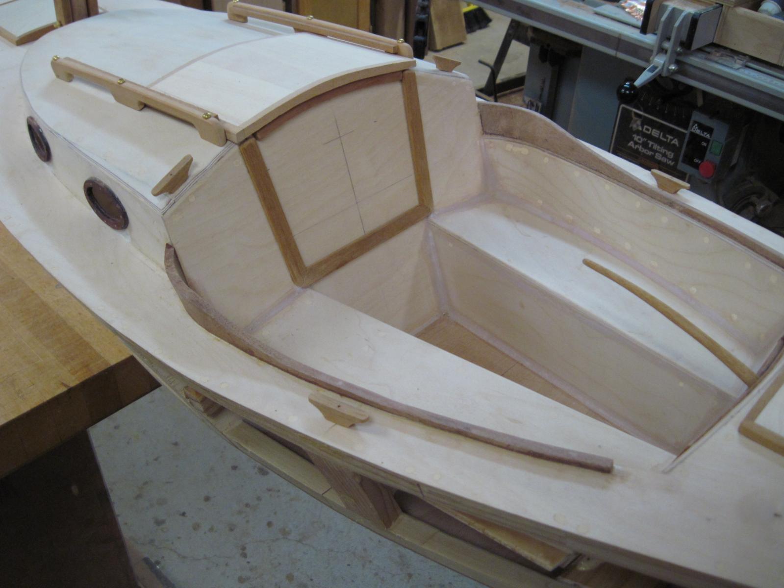
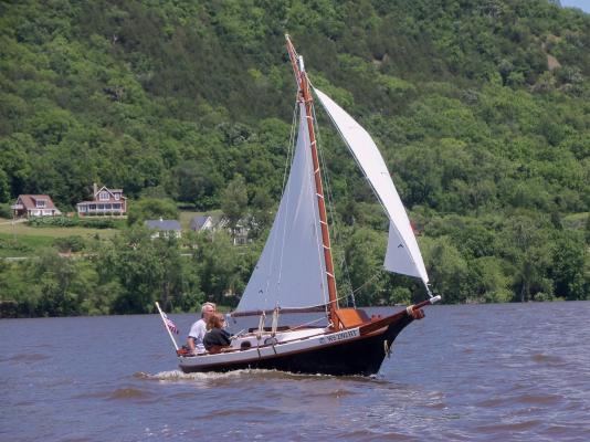
Good eye, Harv! Yes, it is a Weekender. Dave
-
Thanks, Michael. I love working in the larger scales. I'm planning a Bomb Vessel Granado cross section in 1/24 scale. Dave
-
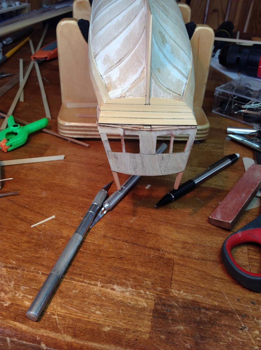
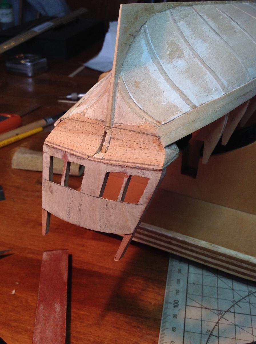
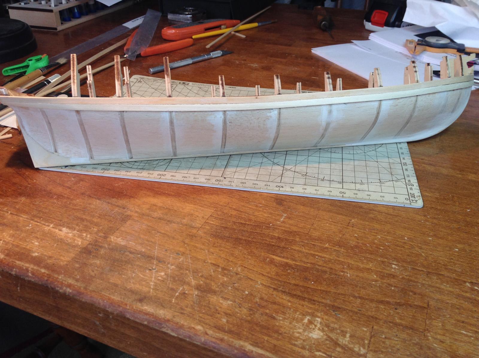
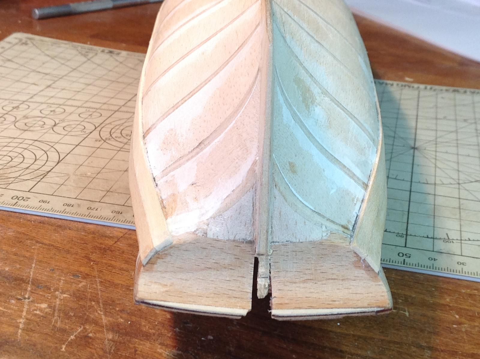
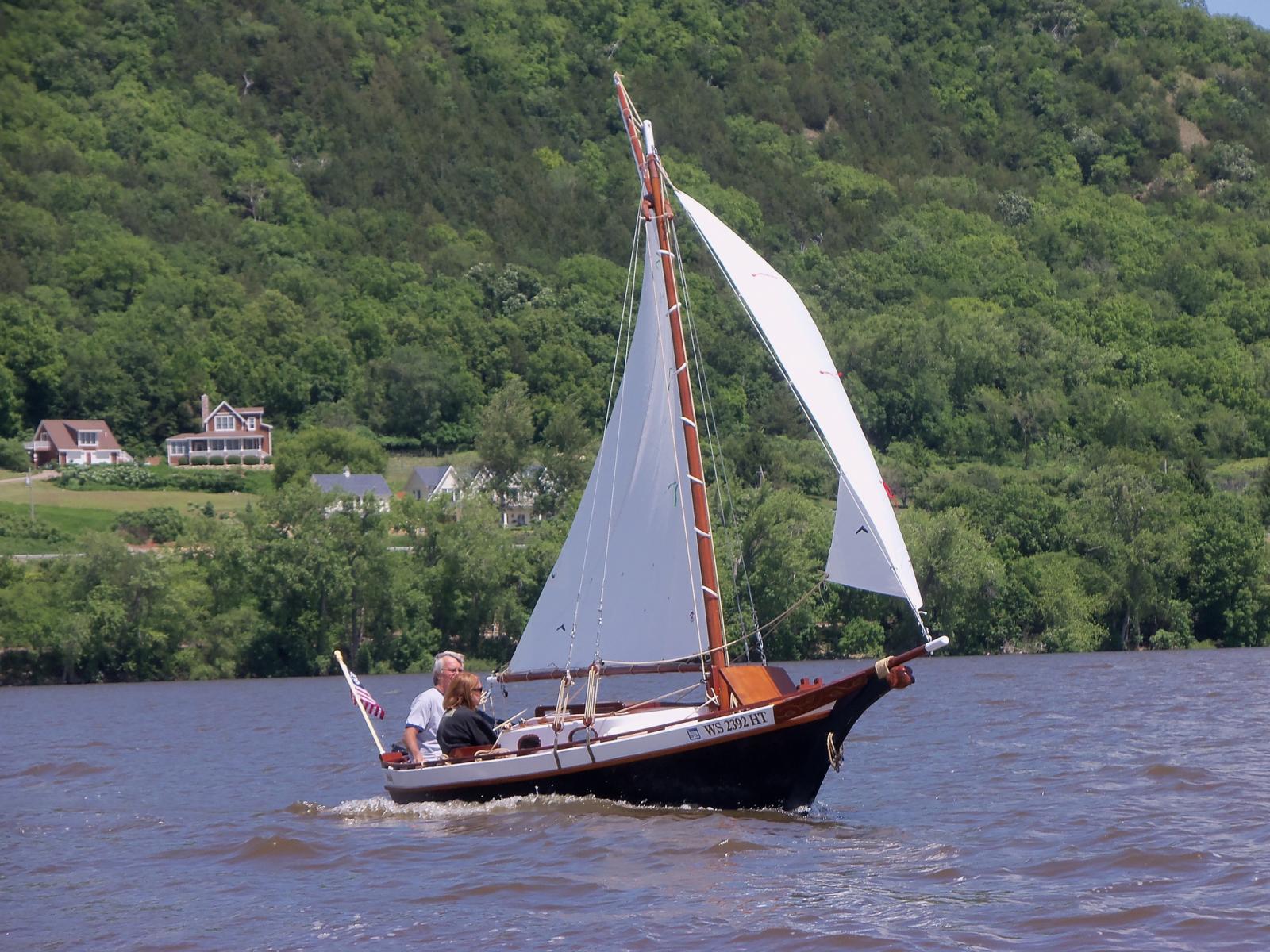
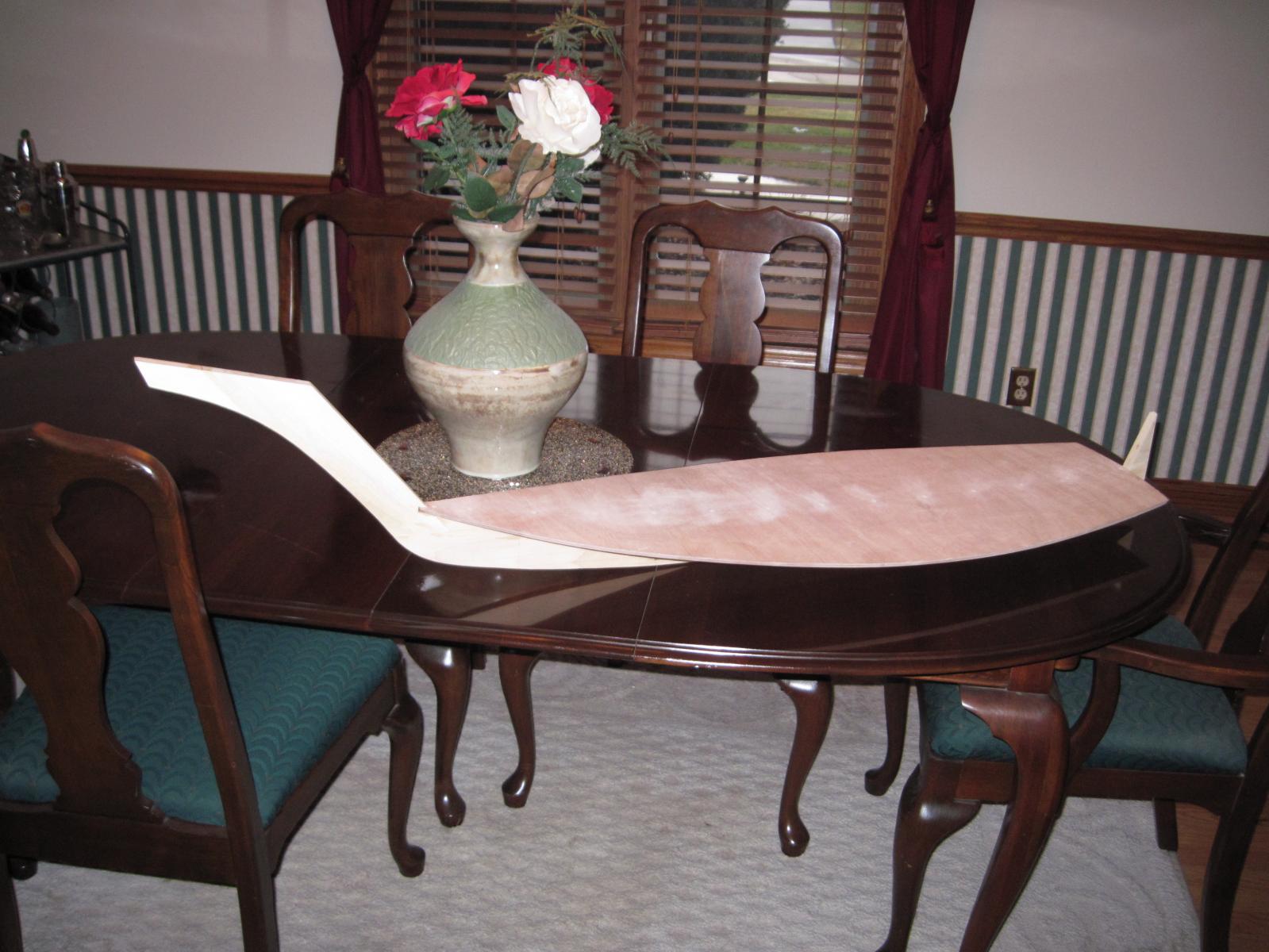
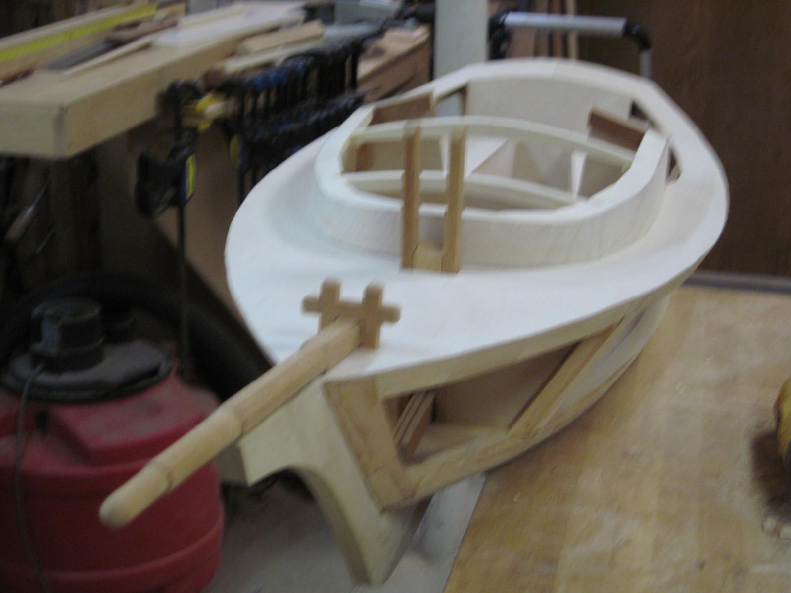
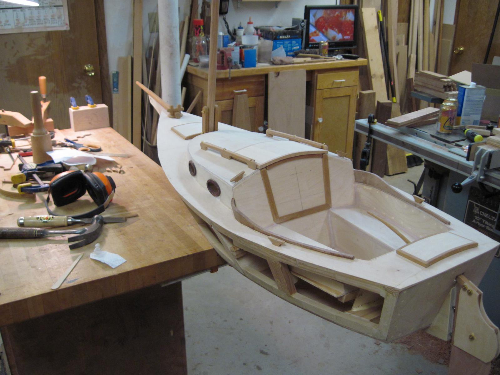
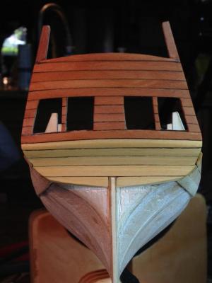
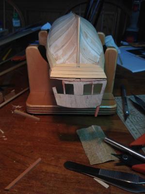
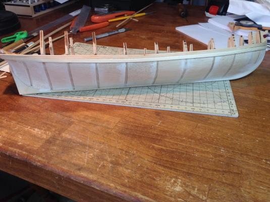
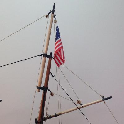
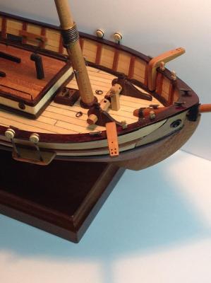
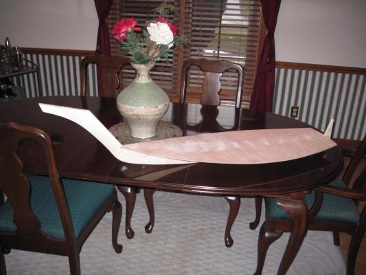
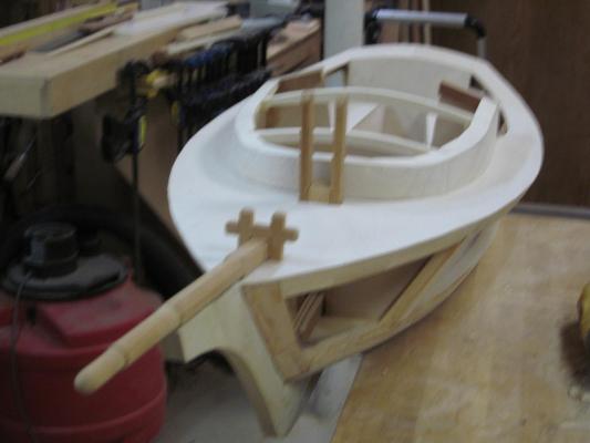
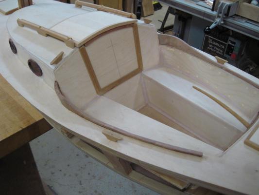
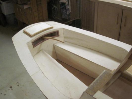
A few years ago, I built a 19', shoal draft, gaff-rigged sloop for my wife and I to sail. We've enjoyed "Molly" immensely. I decided to build a large model of her (1/4 scale, not 1/4" scale!) to display in a large dormer window in our house that faces the street. Construction is similar to how the real boat was built. I started with the keel, then the cabin floor was added. Bulkheads were placed and the deck installed. The cabin trunk was next, followed by rafters and the cabin top. The project has been sitting, untouched for about 2 years, but I decided to get her completed. Here are some photos of the model, and my wife and I sailing the original boat. Dave

-
Brig Eagle by robnbill - 1:48
DocBlake replied to robnbill's topic in - Build logs for subjects built 1801 - 1850
I think the maple frames are going to look great. I love contrast between the maple and the stained cherry keel. Dave -
Brig Eagle by robnbill - 1:48
DocBlake replied to robnbill's topic in - Build logs for subjects built 1801 - 1850
That's incredibly generous of you, Bill! One day I'll repay the favor. I was planning on using the Bodnar practicum for the build, but I'll watch the modifications you are making with interest. I guess what I'm saying is that I'm not sure which set of plans/drawings I'll need (all of them?!). Let me know what you think. I'll PM you with contact into. Thanks again, so much! Dave -
Brig Eagle by robnbill - 1:48
DocBlake replied to robnbill's topic in - Build logs for subjects built 1801 - 1850
Very nice, Bill! I'm very interested in this build as I'd like to try it myself. My problem is that I know absolutely nothing about CAD, and drawing the frames by hand will take the remainder of my life, most likely. Any thoughts about selling your CAD drawings to those of us who can't/won't learn how to do them ourselves in CAD? Dave