DocBlake
-
Posts
1,811 -
Joined
-
Last visited
Content Type
Profiles
Forums
Gallery
Events
Everything posted by DocBlake
-
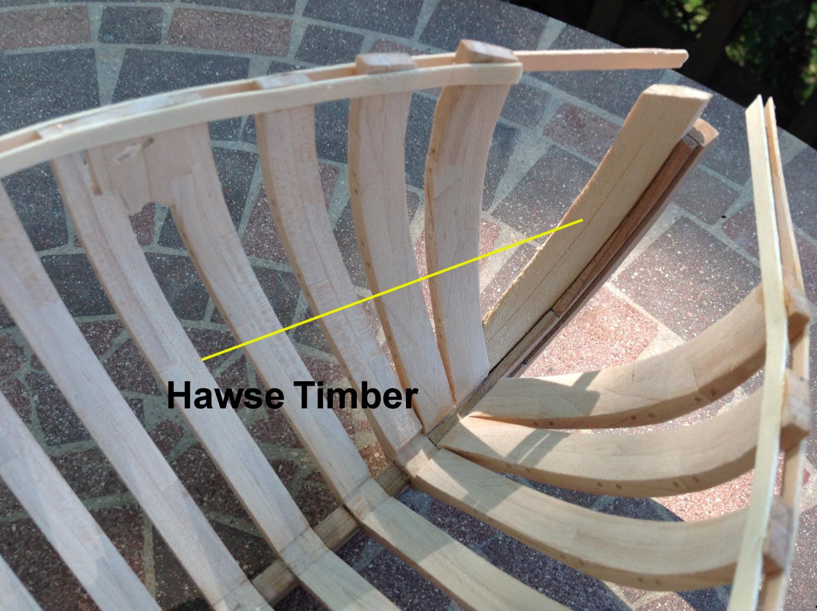
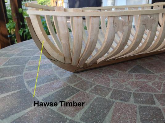
 The hawse frames were completed and glued in place. Overall I'm happy with the fit. The first hawse frame is short, but that should be no problem because the kit was design with the hawse timbers and the first two cant frames long, so they can be custom cut for the model. Frame Q is also glued in place. That's where the wing transom sits. Next is fairing the hull.

- 306 replies
-
- 6
-

-
- armed virginia sloop
- Patrick Henry
- (and 2 more)
-
Two questions for the group: 1) My framing is in hard maple, with cherry for the deck framing. I love the contrast! The kit, however, supplies the wing transom, stern transom framing and counter framing as cherry. While pretty as cherry, I think those parts should be hard maple to be consistent with the rest of the build. I would be willing to make them over in maple. What do you all think? 2) I would like to substitute the bulwark planking, both inboard and outboard with different wood. The kit supplies cherry, but I want to "customize my build a bit. I'm thinking boxwood or yellowheart for the outboard planking down to the black strake/wales, and swiss pear for the inboard planking. I'd also like some ideas for the transom and counter. There's a build of the cutter Cheerful at MSW where the counter is planked in the same color as the inboard bulwarks: red. I'd consider swiss pear for this, just like the inboard bulwarks. the transom itself is planked as the outboard bulwarks: boxwood or yellow heart. What do you think?
- 306 replies
-
- 4
-
-
- armed virginia sloop
- Patrick Henry
- (and 2 more)
-
Thanks, Adam. I appreciate your interest.
-
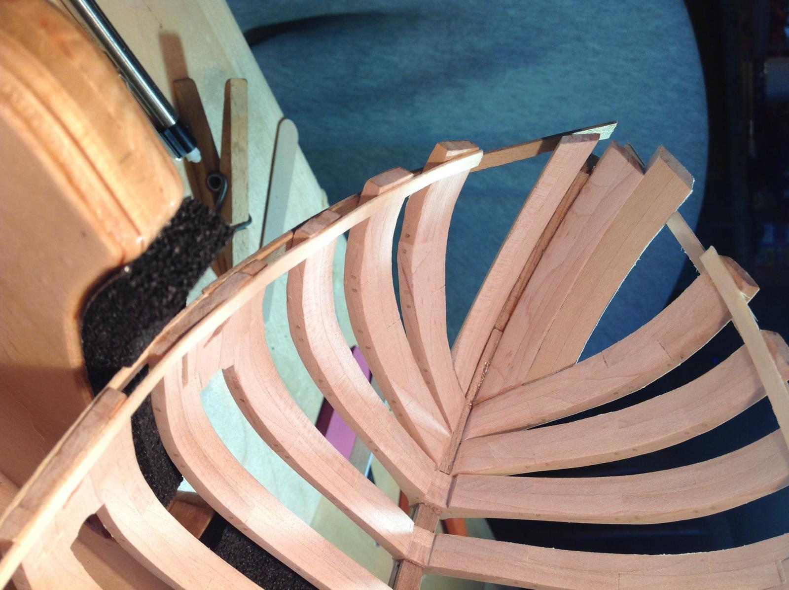
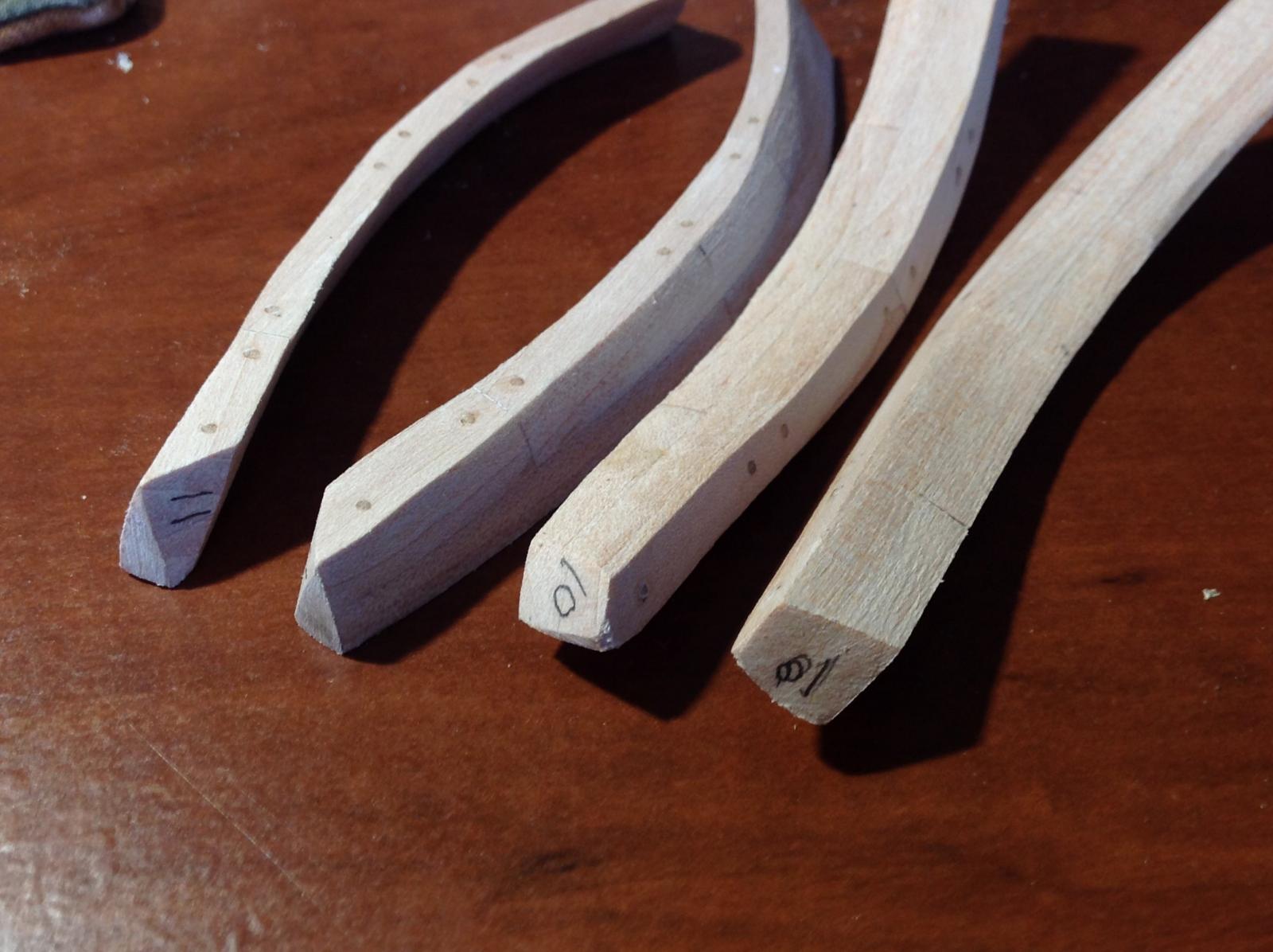
Slow progress on the hawse timbers. I did finish a building cradle for the model, which will be her home in the shipyard until she'd mounted on the display stand. I was satisfied with the fit of the first hawse timbers in bass wood so I fitted the real maple ones and glued them in place. I just finished the bass wood mockup for the second timber and fit it in place. It turned out pretty well. I feel confident in the technique I'm using to shape these complex timbers to the model, and the practice on the bass wood mockups helps a lot. Once the third timbers are mounted, the hull will be faired.


- 306 replies
-
- 11
-
-
- armed virginia sloop
- Patrick Henry
- (and 2 more)
-
Wow! Fantastic detail.
-
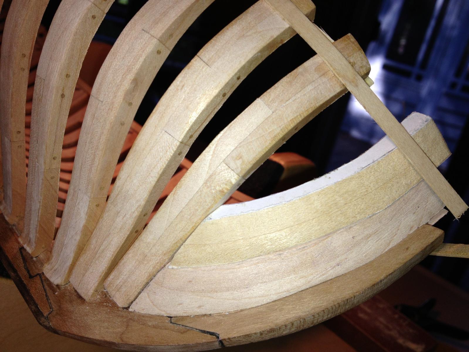
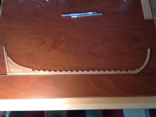
I started work on the hawse timbers. These will be the most difficult part of the framing. Pictured is a basswood mockup I made. It's roughly shaped to size. The real timbers will be hard maple. It took about 1 hour to fit the mockup.

- 306 replies
-
- 7
-
-
- armed virginia sloop
- Patrick Henry
- (and 2 more)
-
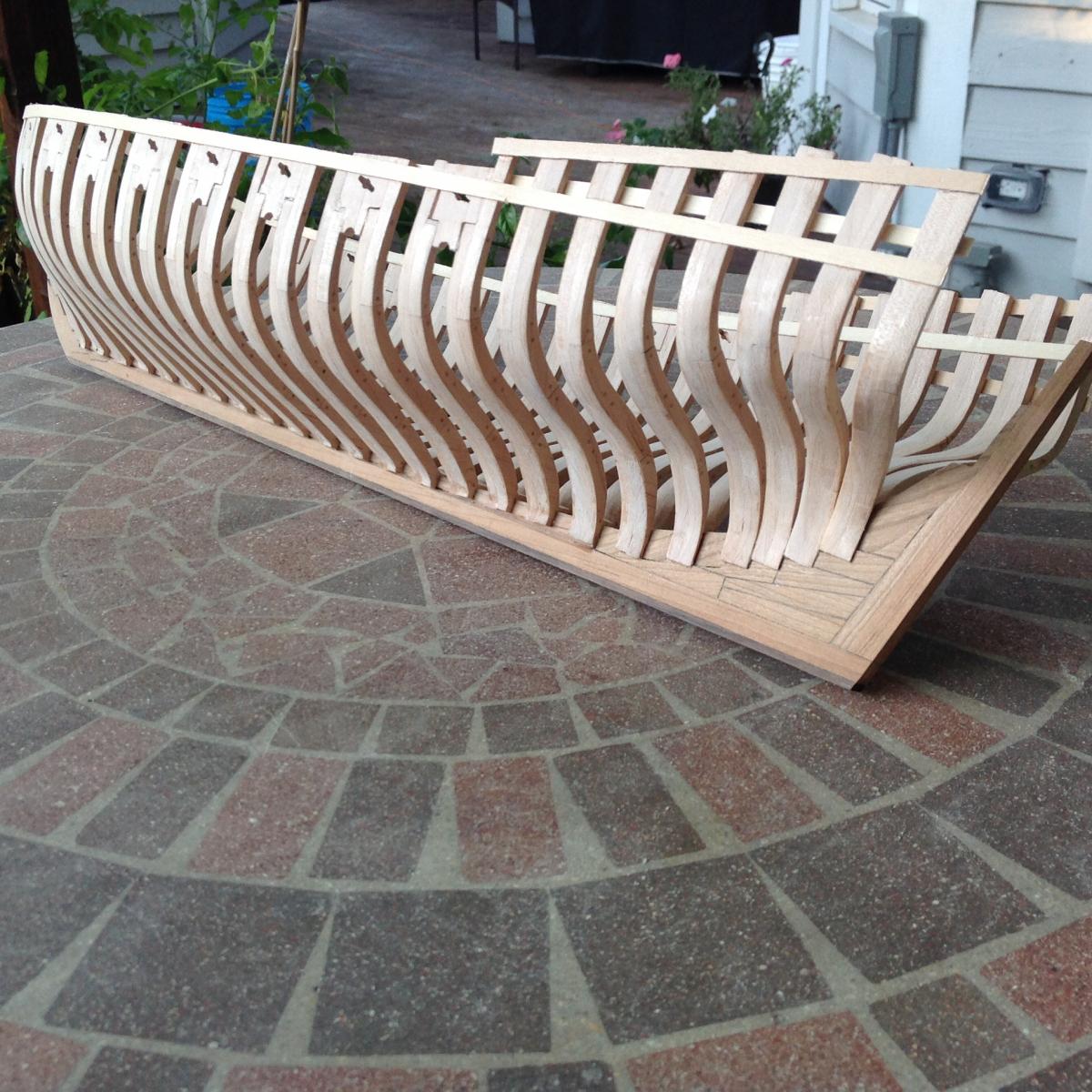
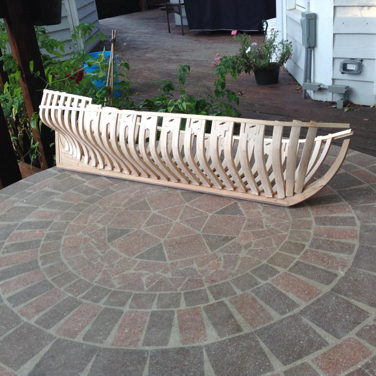
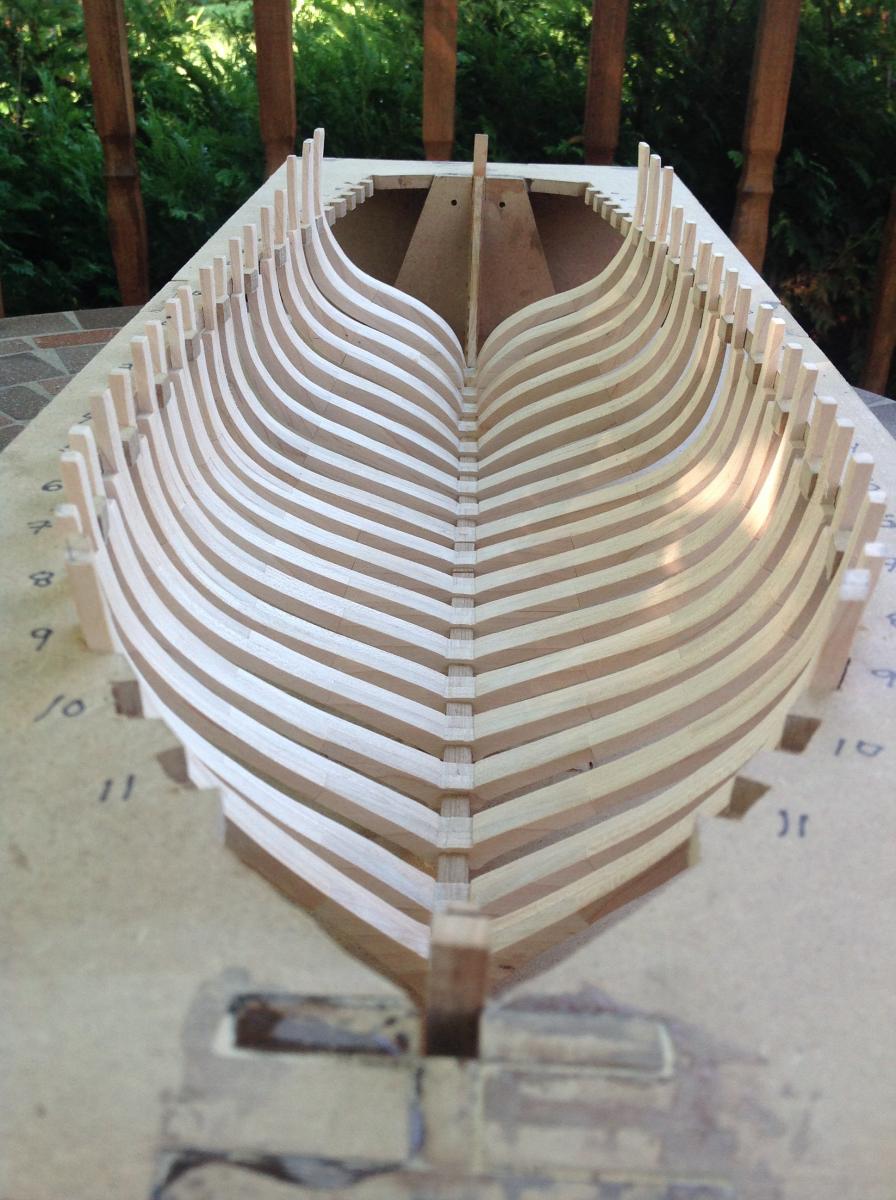
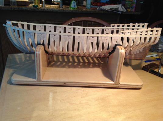
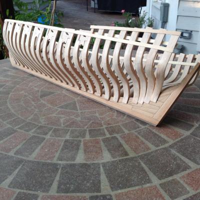
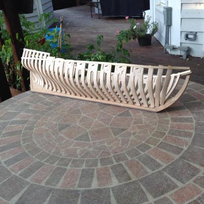
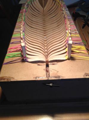
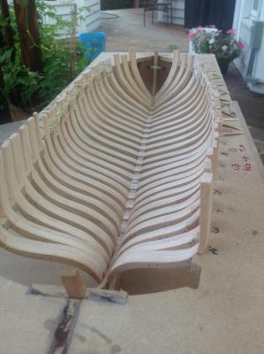
The inside of the ship was faired, as was the outside down to the jig. I installed the temporary battens and removed the ship from the jig. Next up: Fitting the hawse timbers and fairing the outside.
- 306 replies
-
- 12
-
-
- armed virginia sloop
- Patrick Henry
- (and 2 more)
-
Great job on the rigging! (As with everything else!)
-
Thanks, Joel. Progress report: All the frames are now glued in place except for frame Q, per the practicum. I've started fairing the upper parts of the frame before installing the temporary battens. I decided to use my Dremel tool to thin down the filler pieces, which stand proud of the frames by a lot on the inboard side. It makes the work go quicker. Anyway, not much to see, so no photos. As for fairing the inside of the model, Bob Hunt's lofting was quite good. The center-most frames require virtually no sanding at all, except to get them cosmetically smooth. Moving forward, the biggest area that needs sanding is the transition from the full frames to the cant frames. Moving aft, the sanding needs to start as the frames begin rising on the deadwood...around frame J. I'm not implying massive wood removal, either. It's mainly getting the edges of the frames to line up so planking flows smoothly, not removing large amounts of wood. Bob's lofting was very accurate.
- 306 replies
-
- 2
-
-
- armed virginia sloop
- Patrick Henry
- (and 2 more)
-
Grant: Gorgeous work! You continue to set a very high bar. Dave
- 456 replies
-
- 5
-
-
- finished
- bomb ketch
- (and 2 more)
-
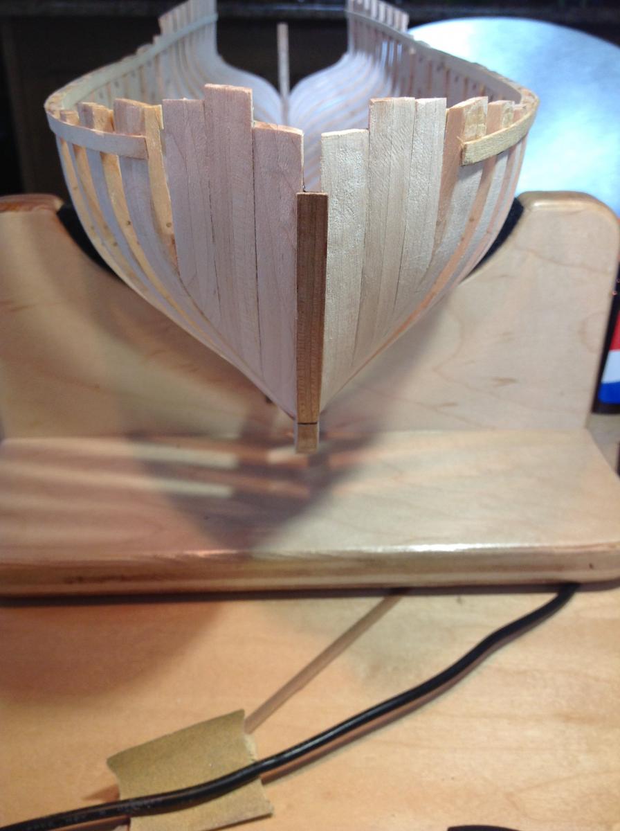
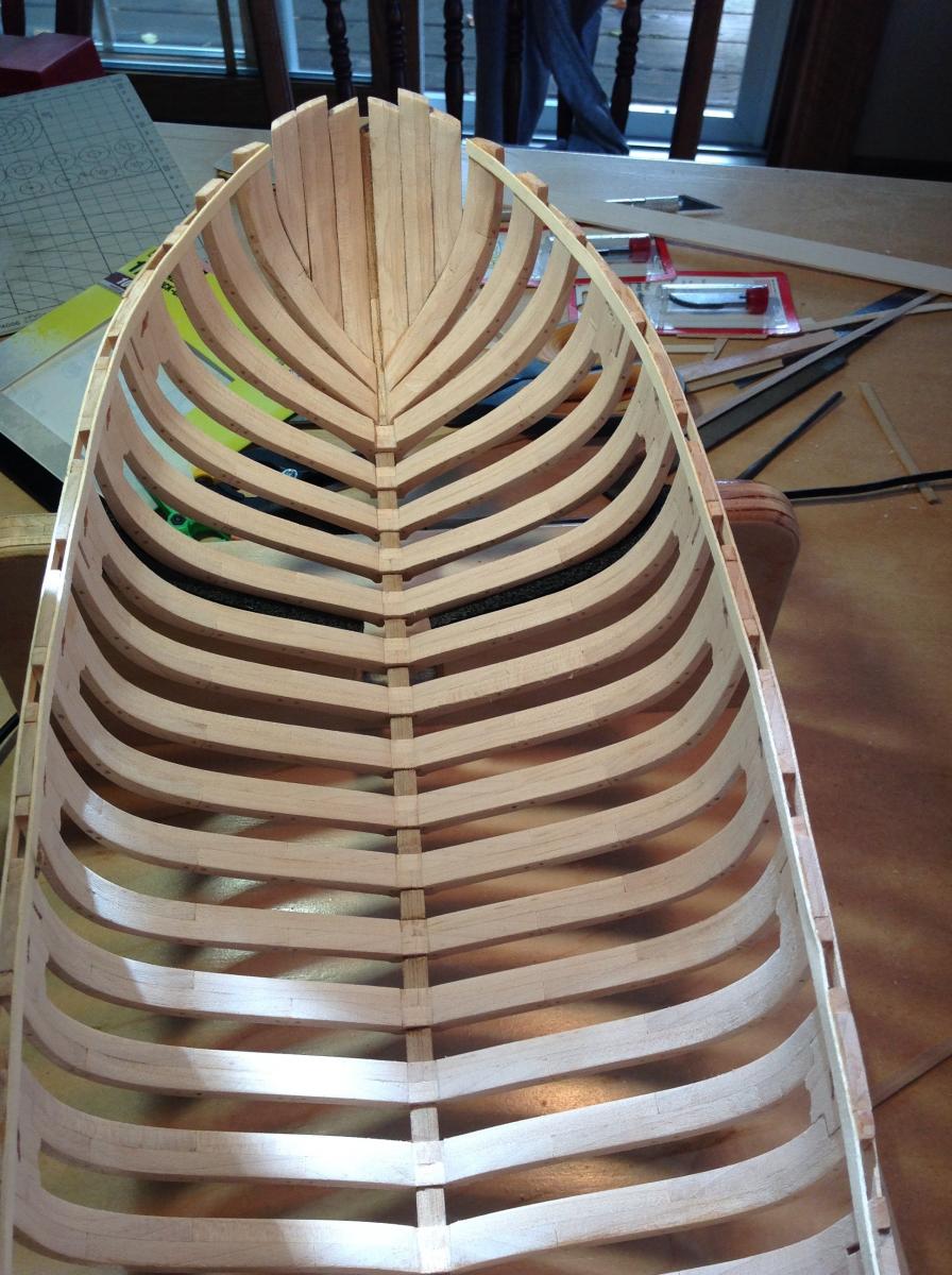
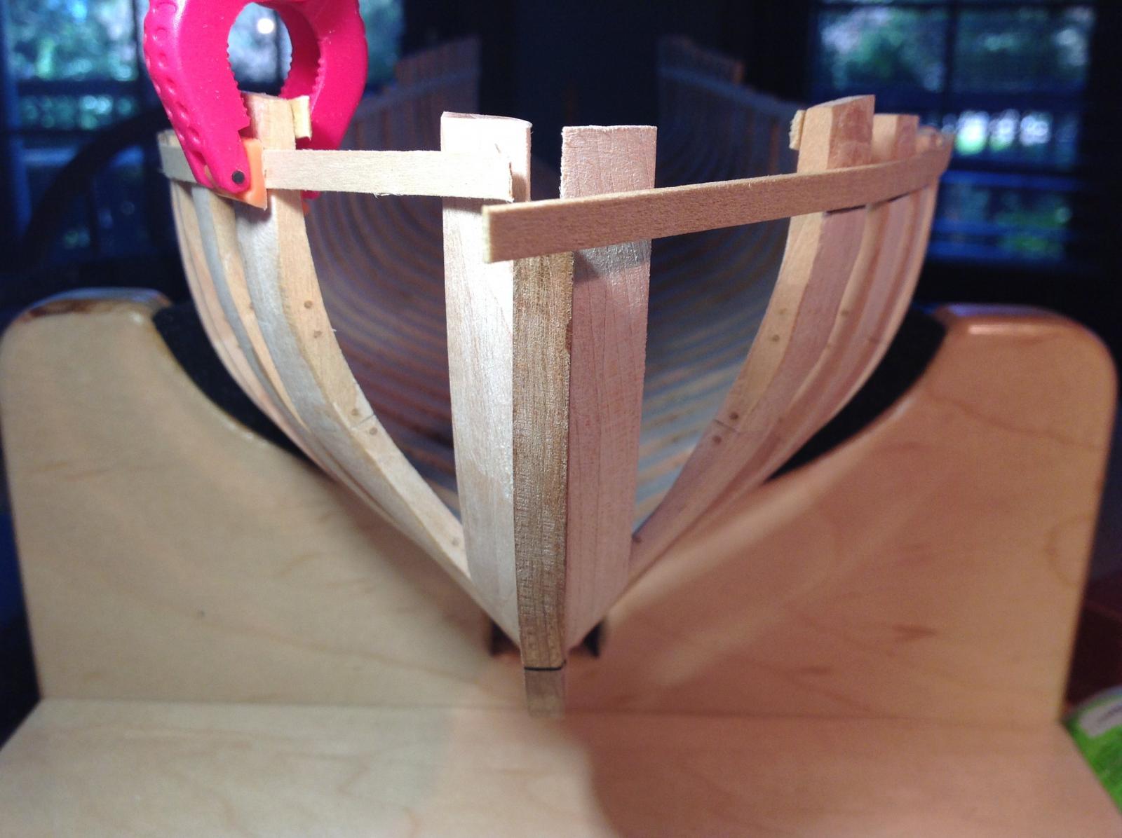
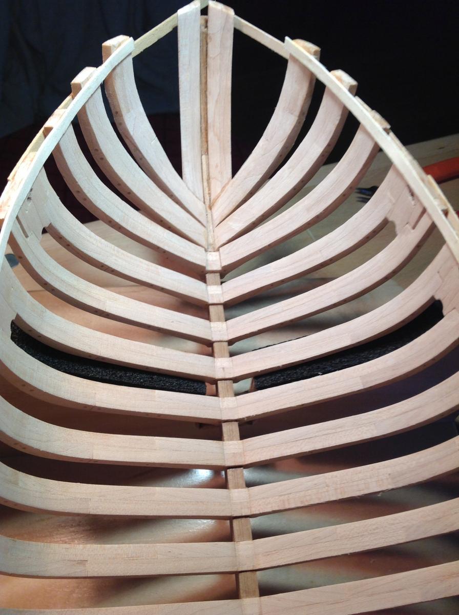
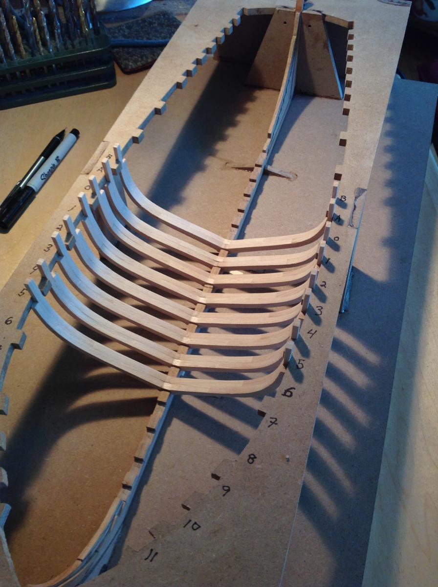
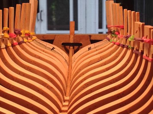
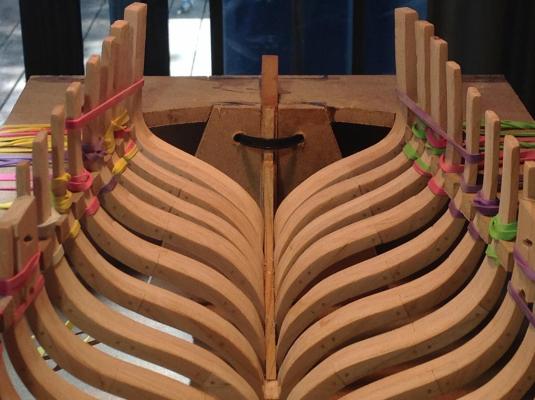
All of the frames are glued to the rising wood and the deadwood except the last two, P and Q. I had to remake the two pair of forward cant frames, because I didn't like the way they fit. They are much better now, and the fairing of the hull will be easier. I did rum into trouble with frame P, the next to the last one. Basically the kit pieces made for a set of frames that tended to "curl in" rather than line up with the upper futtocks of the frames that come before. The size of the finished frame doesn't leave enough excess wood to fair frame P into the same plane as the frames before. So I used the beveling template to make a new pair of frames, and beveled them to fit the hull curves at that station. Cutting out the futtocks and gluing them together is easy...fitting the frame in place without an accurate beveling template is hard. It took me a couple of hours to fit the new frames, but I like the end result. The first photo shows the old frame P. It is the first one. Notice how the upper futtock is rotated inward. The second and third photos shows the new frame P before beveling. The forward edge of the frame is high compared to the frame in front, and the uppermost parts need to be shaped. The last three photos are of the final pair of frames P in position in the jig. The uppermost part flows more smoothly and the inside and outside surfaces are fair compared with the frame before. A great improvement. Once the poly is dry I'll glue this frame in place, fair the upper hull and install temporary ribbands to the frame tops. The model will be ready to come out of the jig,

- 306 replies
-
- 11
-
-
- armed virginia sloop
- Patrick Henry
- (and 2 more)
-
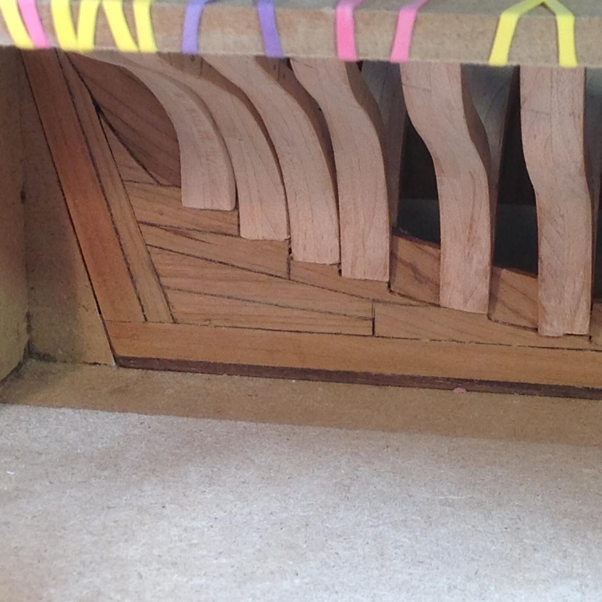
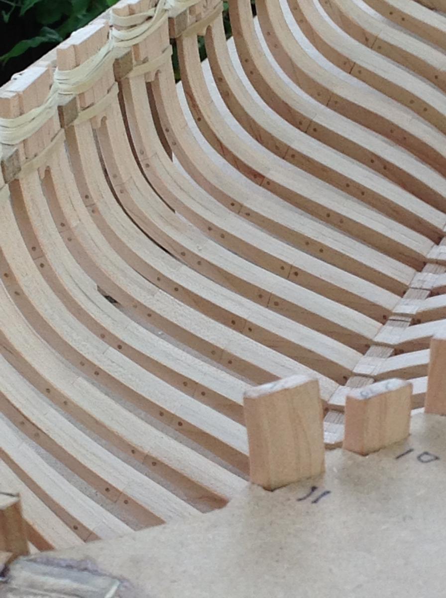
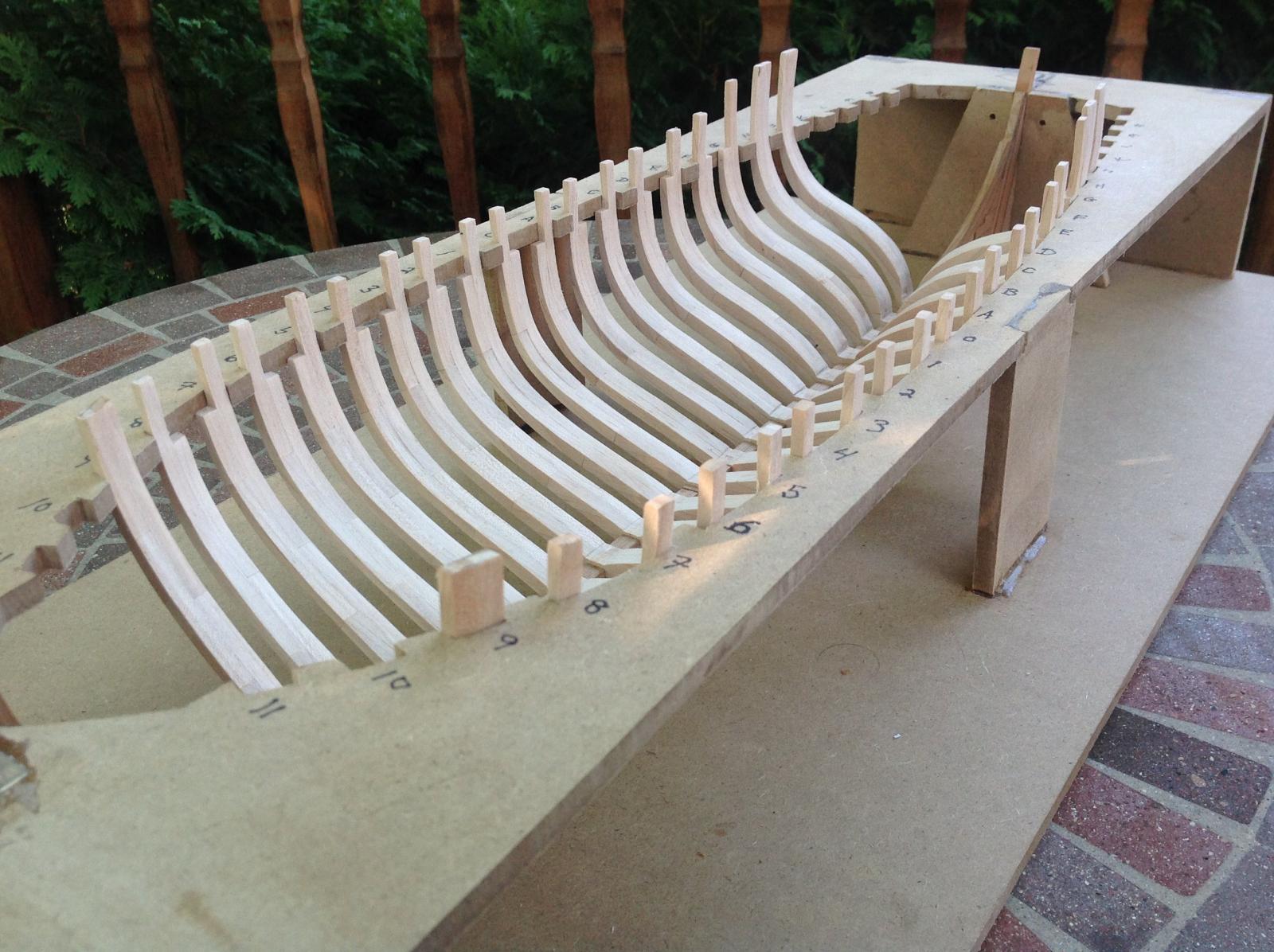
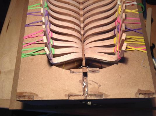
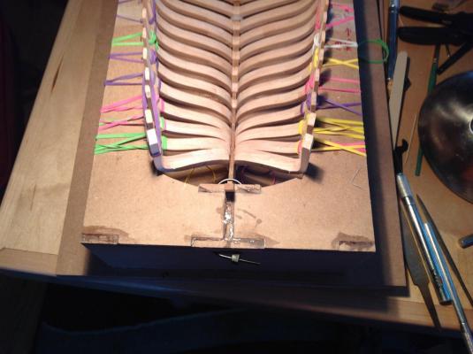
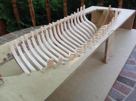
I'm ready to do a little more ship modeling now that we're into September. I completed the frames and treenailed every futtock. Over 800 treenails on the frames alone! I used birch toothpicks and a #57 drill for them, making them a scale 1-1/2" in diameter. Maybe slightly large, but I like the effect anyway. Each frame was then trimmed and sanded to fit the jig. The 8 filler pieces (which define the sweep ports and the scuppers were beveled and sanded to fit between the frames. You can see the paper templates glued to the most forward filler pieces. these were used to accurately sand the rather acute bevel needed to fit these parts where the bow curves the most. The others I did by hand, without using the templates provided. Next is the glue-up. Notice the compound angles that have to be formed to fit the forward cant frames


- 306 replies
-
- 8
-
-
- armed virginia sloop
- Patrick Henry
- (and 2 more)
-
I'm building the POF model Armed Virginia Sloop. The vessel had two elm tree pumps to keep the bilge dry. Would those low-tech pumps have required a lower deck well to protect the bottom end from damage as a chain pump would require? I'd like to add one to the model, combined with a shot locker.
-
I used the same rigging spec sheet for my AVS. The MS rigging line is junk. Throw it away! The blocks are oversized junk...throw them away also. Buy blocks from Chuck Passaro at Syren. I used Amati line, which was pretty good, but Chuck's is far better.
- 831 replies
-
- 5
-
-
- Armed Virginia Sloop
- Model Shipways
- (and 1 more)
-
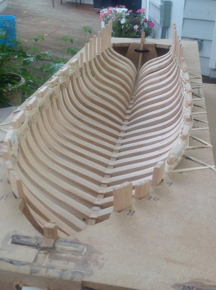
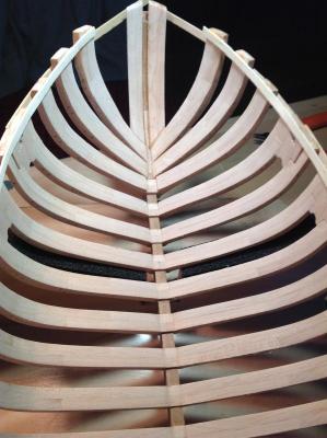
Not a lot going on in the shipyard recently. The Admiral and I just got back from 5 days up in the Door peninsula of Wisconsin. There's a nice collection of quaint waterside towns that remind me of New England seaside fishing villages, only these are in the Midwest! We really enjoyed the little excursion. All the full frames for the sloop have been beveled and fit in place. I laid a plank across the framing both inboard and outboard and it looks like there will be very little fairing to be done because of the pre-beveling of the frames before installation. That's a relief! The only mistake so far: I installed frame H backwards, with the floor facing forward instead of aft. The beveling is all correct...I just got a little confused when laying out the bevel pattern. I'm not rebuilding the frame, because I'm neither entering this ship in a contest, nor expecting my build to be examined by an expert in historic naval architecture.

- 306 replies
-
- 13
-
-
- armed virginia sloop
- Patrick Henry
- (and 2 more)
-
Brig Eagle by robnbill - 1:48
DocBlake replied to robnbill's topic in - Build logs for subjects built 1801 - 1850
Eagle is coming along great. An inspiring build! -
Nice work, Brian. What kind of mill do you have? Are you happy with it or would you buy something else if you had it to do over? I'm in the market for one, but am just beginning to research it.
- 831 replies
-
- 2
-
-
- Armed Virginia Sloop
- Model Shipways
- (and 1 more)
-
All my frames are glued up. The first 8 have been sanded and beveled as needed and are sitting on the keel assembly in the building jig. My frames are hard maple, the keel assembly is cherry. Final fairing of the maple by hand is not going to be too easy! Dave

- 306 replies
-
- 10
-
-
- armed virginia sloop
- Patrick Henry
- (and 2 more)
-
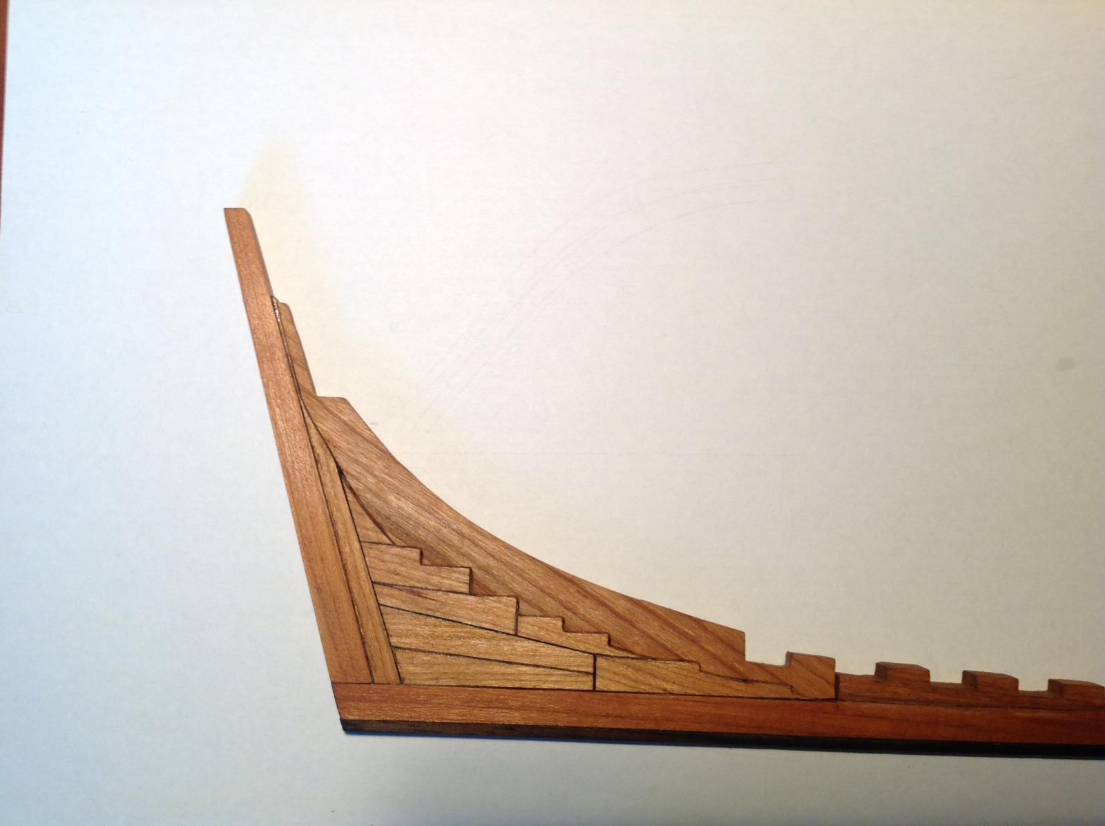
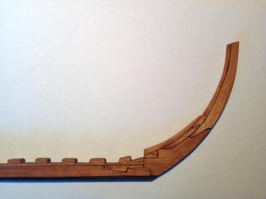
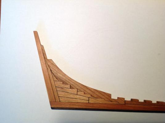
I finally finished the keel. The first step was to glue the stern deadwood in place. The rosewood false keel was fitted and glued. Next I cut the rabbet by adding a bevel to the top of the keel and the bottom of the rising wood. Then the rising wood was glued in place and the notches squared. Finally came the stem and the stem deadwood. Once I finish beveling the frames, it'll be time to start framing the hull. Dave
- 306 replies
-
- 11
-
-
- armed virginia sloop
- Patrick Henry
- (and 2 more)
-
The rising wood was carefully removed from the billet and all the appropriate frames were fitted to the slots. The slots were squared up and the keel is ready to be glued up. I went a little out of sequence here by fitting the frames to the rising wood before beveling them, but I don't think it makes any difference. The strip of dark wood in the picture is rosewood, which I will use for the false keel
- 306 replies
-
- 9
-
-
- armed virginia sloop
- Patrick Henry
- (and 2 more)
-
Brig Eagle by robnbill - 1:48
DocBlake replied to robnbill's topic in - Build logs for subjects built 1801 - 1850
Very, Very nice! -
Beautiful craftsmanship. The Bomb Vessel is spectacular.
- 456 replies
-
- 2
-
-
- finished
- bomb ketch
- (and 2 more)
-
Thanks, John. That's helpful!