DocBlake
-
Posts
1,811 -
Joined
-
Last visited
Content Type
Profiles
Forums
Gallery
Events
Everything posted by DocBlake
-
 Beautiful build. It makes me want to start mine...but I need to get a little more experience before attempting this POF scratch build. I purchased the Lauck Street Shipyard's POF kit "Armed Virginia Sloop" and will soon start a build log. Hopefully this will boost my experience level and make the Granado cross section doable! BTW: If you've not seen the Lauck Street kit, it is awesome! The 3/8" scale makes a fairly large admiralty model. The build style is similar to Harold Hahn's, with sistered frames. I ordered mine with hard maple frames and cherry keel and deck framing for contrast. A beautiful kit. http://www.lauckstreetshipyard.com/avskitpmt.htm
- 456 replies
-
- 1
-

-
- finished
- bomb ketch
- (and 2 more)
-
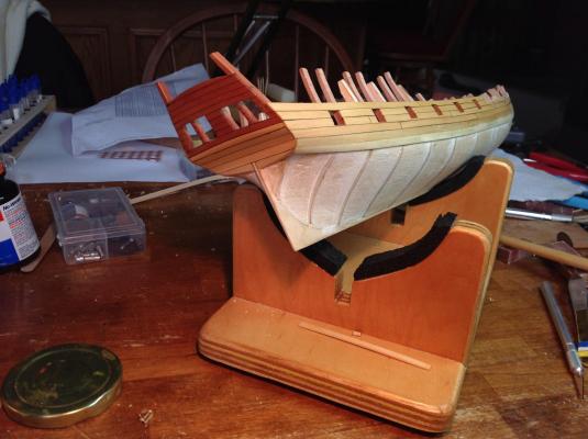
I cut the oar sweeps into the bulkhead planking. They turned out OK despite being a little "off" from the Hahn plans.
-
Jon, thanks for the heads-up on the sheaves. I'll look into it.
-
Thanks, Brian.
-
Excellent job rigging the cannons, Brian. Don't add the riding bitt to the deck until after the mast is stepped and the spreader yard horse is rigged. It will be impossible to rig it with the bitt in place.
- 831 replies
-
- 2
-
-
- Armed Virginia Sloop
- Model Shipways
- (and 1 more)
-
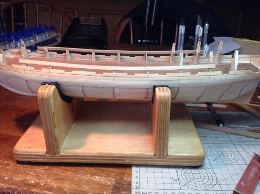
Very slow progress due to outdoor projects commissioned by the Admiral. I've finished framing the gun ports in swiss pear. Next up is cutting the oar sweeps. I laid out the sweep ports and found that two of them fell directly on the kit bulkheads. Not wanting to remove those bulkheads because the plywood is very hard and I need them for supporting the planking, I relocated three of the sweep ports. The last one aft was moved forward from where the Hahn plans call for by about 8 scale inches. Port #4 from the bow had to move the most: 2-1/2 scale feet aft. Port #3 was moved 8" back. I cut out little squares of pin striping tape and attached them to show the sweep locations. Overall I think the placement is pleasing to the eye if not strictly correct according to Hahn's plans.
-
Question about stoves and how the rotisserie worked
DocBlake replied to Modeler12's topic in Nautical/Naval History
Modeler12: If your contention is that the spit was hand cranked by cabin boys or crew, then there is an important design feature you must explain. Why the elaborate gear and chain setup connecting the lower spit (which you presumed was hand-cranked as the only source of power) with the upper shaft which passes through the flue and is attached to a fan? Totally unnecessary and superfluous according to your theory. Why was it there? What function did it serve? As you know, there was nothing on a ship that didn't serve a purpose. -
Nice job so far. This build is in my queue, so I'm watching with interest! Dave
-
Nice job so far! I didn't care for the Britannia metal wheel so I bought a boxwood wheel from MS. I sanded it down on the disc sander to the proper thickness, then stained it a red mahogany color. It turned out nice, I think. Dave
- 831 replies
-
- 1
-
-
- Armed Virginia Sloop
- Model Shipways
- (and 1 more)
-
Brig Eagle by robnbill - 1:48
DocBlake replied to robnbill's topic in - Build logs for subjects built 1801 - 1850
Great job on the Brodie stove, Bill. Your model is beautiful. Keep up the good work! Dave -
Thanks, Martin. You're right, "Rattlesnake" is a lovely ship. I especially like the tumblehome! Can you post a link for your "Rattlesnake" build? Dave
-
Magnificent work, Jonathan! Dave
-
Jon: I've been trying to hold the razor blade stationary and move the cutting disk. I'll get the hang of it! Ditto in regard to the milling machine. I have a Dremel drillpress also, and while it has it's uses, it has lots of flaws; lack of precision being number one. Dave
-
Jon: I have the cutting disks and the mandrel (I should say the 10 mandrels I was forced to buy as a package!). I've already broken three discs and gone through a half dozen razor blades practicing. I'll get it eventually. Once you got an acceptable profile, did the one blade work for all the molding needed? Did it hold up and cut cleanly without breaking? Dave
-
I'm working on the planking above the wales. I have one more plank on each side at the bow before the main rail goes on. I've enlarged the gun ports to their final size. You can see the swiss pear framing for the ports that matches the planned inner bulwark planking. Jonathan or any other kit bashers: Any tips on how best to make the scraper to form the profile on the main rail? Dave
-
Very nice build. How did you do the transom? Dave
-
Lots of outdoor chores have limited my modeling time. I have accomplished some, though. I framed the gun ports in swiss pear to match the planned swiss pear inner bulwark planking. This involved gluing Hahn frame segments to form the gun port sides, and then installing a pear sill across the bottom. I'll install the top sill when the planking is done and the top of the gun ports are cut into the planking. I'm working on fairing the inboard surface of all the framing, and need to remove several of the kit bulkheads as part of the process. All this is fairly tedious, and progress is slow. Fairing and/or removing the kit bulkheads (as opposed to the Hahn frames) is really tough because they're made of plywood that seems as hard as steel! I'll get it done, though. Dave

-
Brig Eagle by robnbill - 1:48
DocBlake replied to robnbill's topic in - Build logs for subjects built 1801 - 1850
I'm really loving this build! It's an inspiration. Very nice job. I'd love to build her, but I'm going to have to teach myself CAD. BTW, thanks again for the plans, Bill! -
Swift bowsprit brass band
DocBlake replied to Cabbie's topic in Metal Work, Soldering and Metal Fittings
Any kind of snips will work. If you have a propane torch, heat the brass to red hot to anneal it. It will soften and bend much easier. You 'll probably be able to cut it with a pair of household scissors. Dave -
Swift bowsprit brass band
DocBlake replied to Cabbie's topic in Metal Work, Soldering and Metal Fittings
Hi, Chris! That's exactly how I did each of those fittings on "Swift". You don't have to solder the ring to the brass cylinder, though. Just drill a hole and use a whole eye bolt. If you plan to continue with model ship building, do what I did: buy a drill press attachment for your Dremel tool. I use it all the time. Well worth the investment. http://www.walmart.com/ip/Dremel-Drill-Press-220-01/15638688 Dave -
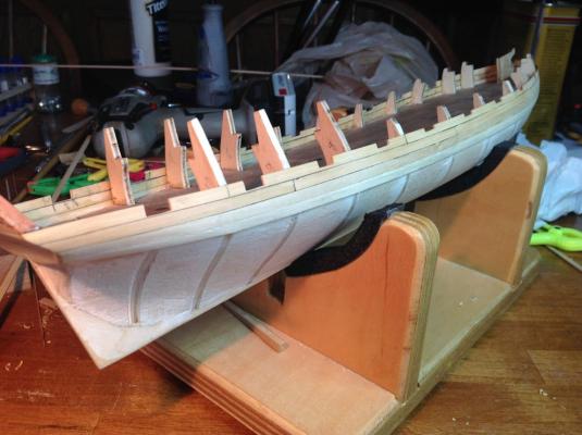
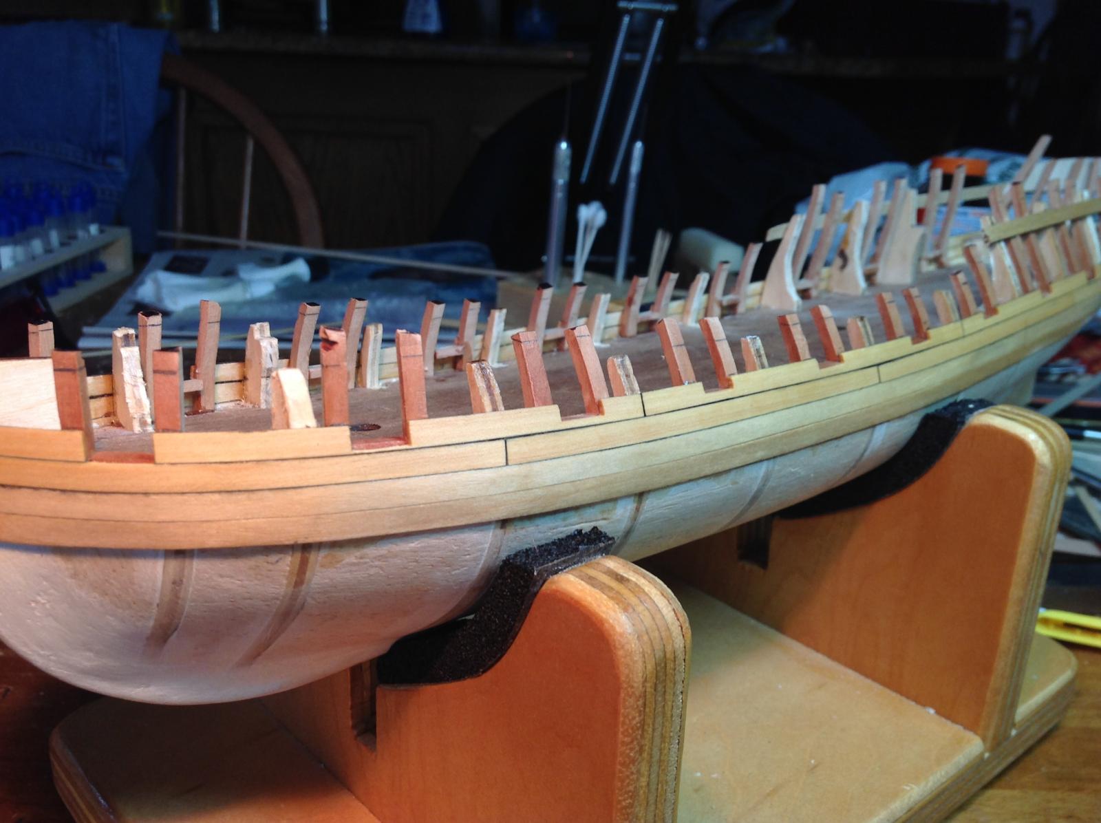
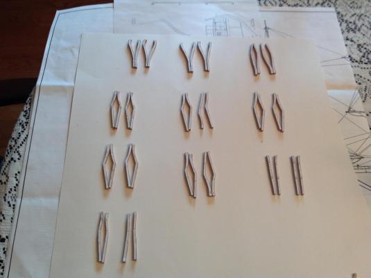
I cut out all the false frames for the gun ports out of swiss pear. Next they get glued in place. I attached temporary planking along the top of the bulkheads to help with alignment. Rather than starting aft and moving forward, I'll begin amidships where the frames have no bevel. I'm deviating from the practicum by installing the after frame first, then the lower sill, and finally the forward frame for each port. Rather than cut all the sills to 3/8", I'll cut each one for a custom fit. My port cutouts may not be EXACTLY 3/8' WIDE Dave
-
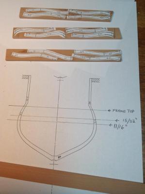
I'm beginning to work on framing the gun ports. I'm using swiss pear so the inner lining of the port matches the inner bulwark planking. The frames for the ports are actually a portion of the frames on the Hahn plans . They extend from the deck line to the top of the bulwark. I've cut out some templates and glued them to the swiss pear. I'll then cut them out, bevel the ones that need it and glue them in place. I did find an error in the practicum here, though. Frames #24 and #26 form gun port 9, the third from the transom. The practicum has you draw a line across the frame at a point where the frame is at deck level. It states that #24 should have the line drawn 15/32" below the top of the frame. The Hahn plans show that this distance should be 11/16". Otherwise all the other measurements are accurate. Next I cut out the frames and bevel as needed. Fortunately only a small portion of the most extreme frames fore and aft require a bevel. Most of the frames have no bevel to contend with. Dave
-
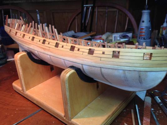
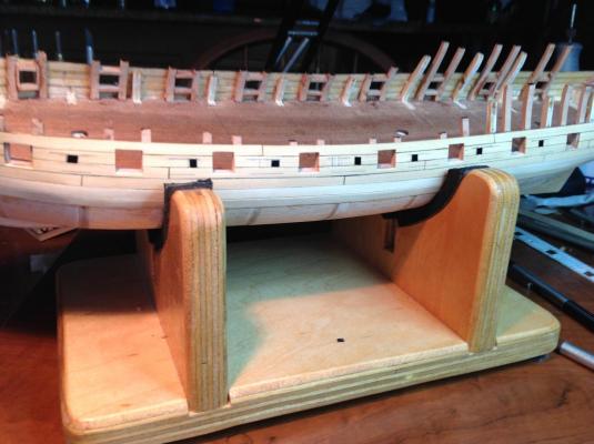
Sorry for the misunderstanding. The photo above showing the gun port measurements is from Bob Hun't practicum. I'm not quite so far along. I did locate the gun ports and cut them into the second strake of planking. I used the cardboard template to locate a couple of the amidships ports, made sure all were the same height above the deck. I measured the location of the fore and aft ports rather than introducing the error that the 2D template would bring to the 3D model. All the port bottoms are the same distance above the subdeck - 9/32". The distance between ports, from the aft edge of a port to the forward edge of the one behind it is 1-1/8", measured along the curve of the hull. Dave