Jack H
-
Posts
345 -
Joined
-
Last visited
12 Followers


Recent Profile Visitors
5,729 profile views


-
 Jack H reacted to a post in a topic:
HMS Portland 1770 by scrubbyj427 - 1:48 - 4th rate 50-gun ship
Jack H reacted to a post in a topic:
HMS Portland 1770 by scrubbyj427 - 1:48 - 4th rate 50-gun ship
-
Jack H reacted to a post in a topic:
HMS Portland 1770 by scrubbyj427 - 1:48 - 4th rate 50-gun ship
-
Jack H reacted to a post in a topic:
HMS Portland 1770 by scrubbyj427 - 1:48 - 4th rate 50-gun ship
-
Jack H reacted to a post in a topic:
HMS Portland 1770 by scrubbyj427 - 1:48 - 4th rate 50-gun ship
-
Jack H reacted to a post in a topic:
HMS Portland 1770 by scrubbyj427 - 1:48 - 4th rate 50-gun ship
-
Jack H reacted to a post in a topic:
Portland Scale Ship Co. news and updates
-
Jack H reacted to a post in a topic:
Portland Scale Ship Co. news and updates
-
Jack H reacted to a post in a topic:
HMS Portland 1770 by scrubbyj427 - 1:48 - 4th rate 50-gun ship
-
Jack H reacted to a post in a topic:
Syren Ship Model Company News, Updates and Info.....(part 2)
-
Jack H reacted to a post in a topic:
HMS Portland 1770 by scrubbyj427 - 1:48 - 4th rate 50-gun ship
-
Mark P reacted to a post in a topic:
HMS Cumberland 1774 by Jack H - 1:36 &1:48 - POF - kit development for True Image Models
-
Mark P reacted to a post in a topic:
HMS Cumberland 1774 by Jack H - 1:36 &1:48 - POF - kit development for True Image Models
-
Mark P reacted to a post in a topic:
HMS Cumberland 1774 by Jack H - 1:36 &1:48 - POF - kit development for True Image Models
-
Stavanger reacted to a post in a topic:
HMS Cumberland 1774 by Jack H - 1:36 &1:48 - POF - kit development for True Image Models
-
Stavanger reacted to a post in a topic:
HMS Cumberland 1774 by Jack H - 1:36 &1:48 - POF - kit development for True Image Models
-
CiscoH reacted to a post in a topic:
HMS Cumberland 1774 by Jack H - 1:36 &1:48 - POF - kit development for True Image Models
-
fake johnbull reacted to a post in a topic:
HMS Cumberland 1774 by Jack H - 1:36 &1:48 - POF - kit development for True Image Models
-
scrubbyj427 reacted to a post in a topic:
HMS Cumberland 1774 by Jack H - 1:36 &1:48 - POF - kit development for True Image Models
-
Cpt.Barbossa reacted to a post in a topic:
HMS Cumberland 1774 by Jack H - 1:36 &1:48 - POF - kit development for True Image Models
-
ccoyle reacted to a post in a topic:
HMS Cumberland 1774 by Jack H - 1:36 &1:48 - POF - kit development for True Image Models
-
 Chapter 3 will still focus on frames, and this topic will continue through to Chapter 5.
 -
After a one-month delay, the new third chapter of components has been sent to Liu, and he has started the new assembly work.
-
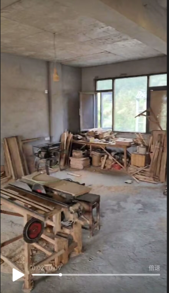
A tiny bit of progress, As you can see, using some new technologies makes this complex POF ship model relatively simple. Even if you’re a beginner, with just a little practice, you can assemble a decent complex model by yourself. And if you’re an experienced builder, it will save you a lot of time—maybe even years. I’m moving all my equipment from the garage to a new space, so I’ll pause updates for about two weeks. This’ll be my new studio, but it’s still a woodworking shop right now. I think this will help me develop some projects better.

-
A bit of progress, The appearance of the filling timber after assembly


-
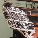
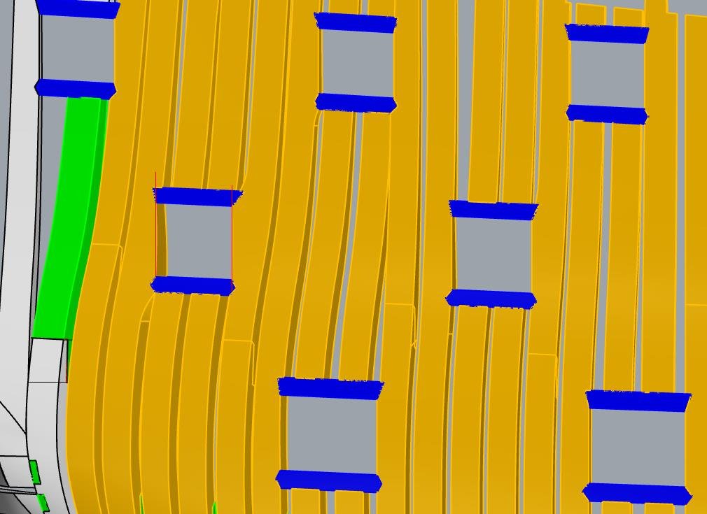
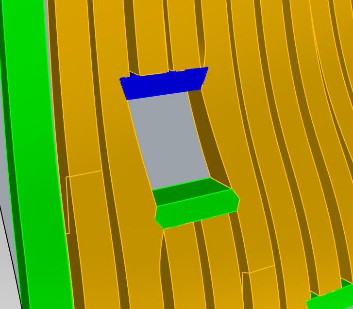
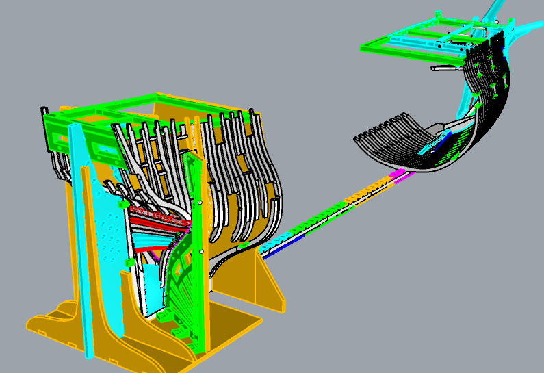
Thank you Matthias, I've also noticed your question. From the right view of the design, this GunPort is indeed vertical, but from many perspectives, it appears slanted.Regarding the size, especially the height and width of the GunPort, they seem disproportionate. This is likely due to the perspective. Please refer to the 3D simulation diagram.
-
A little progress,

-
A little progress,
-
Little Progress


-
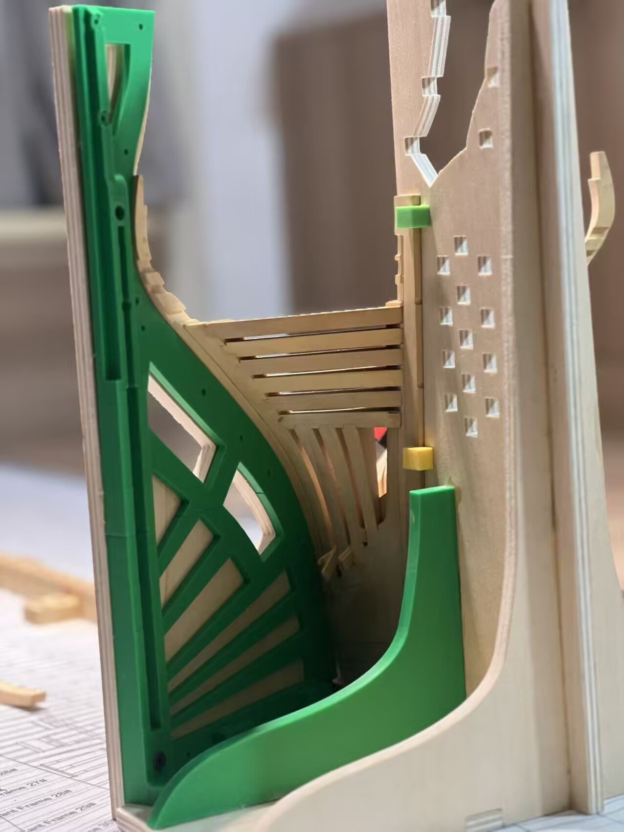
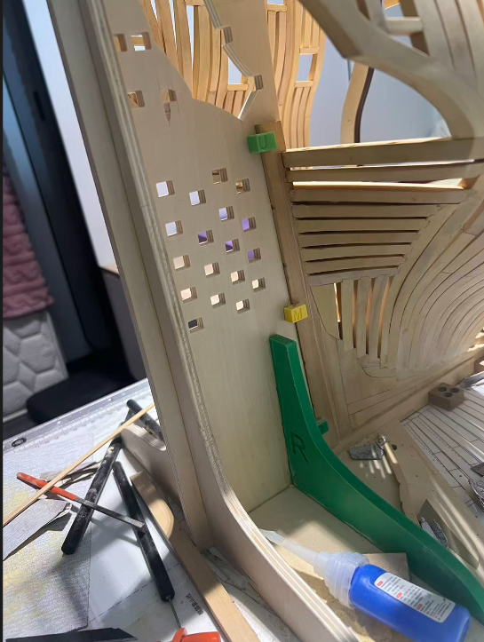
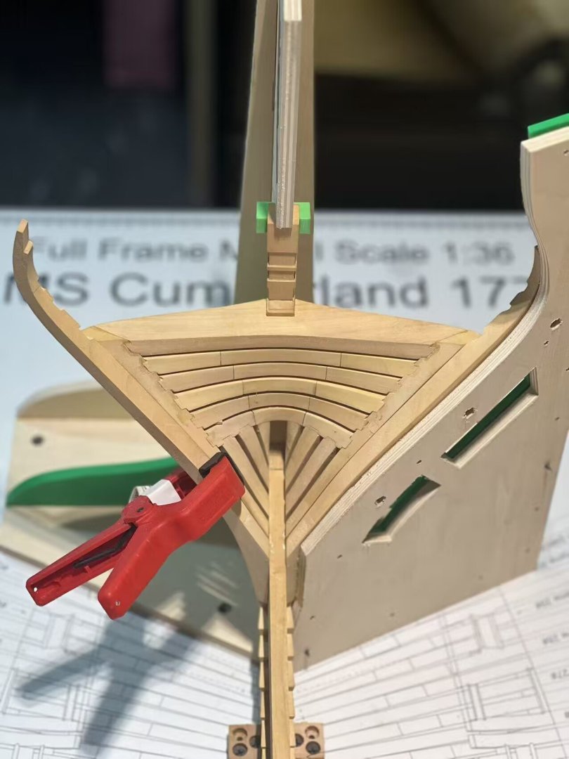
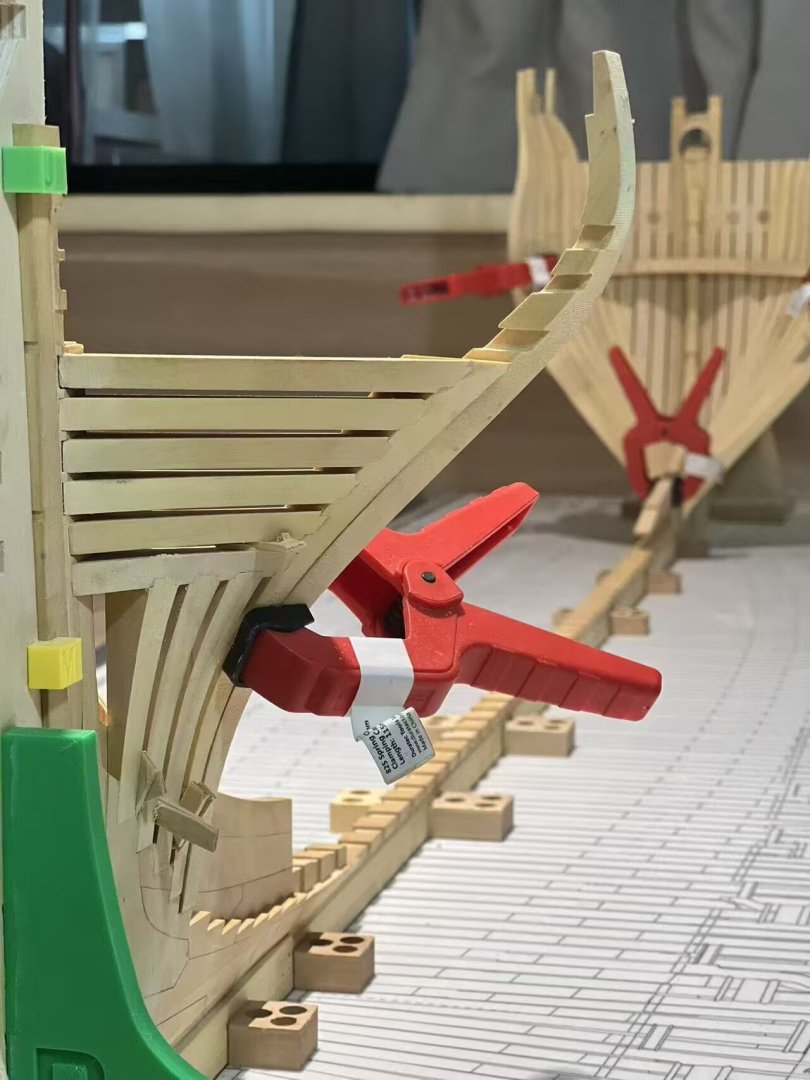
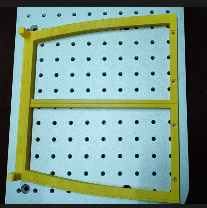
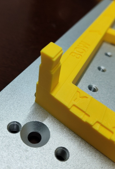
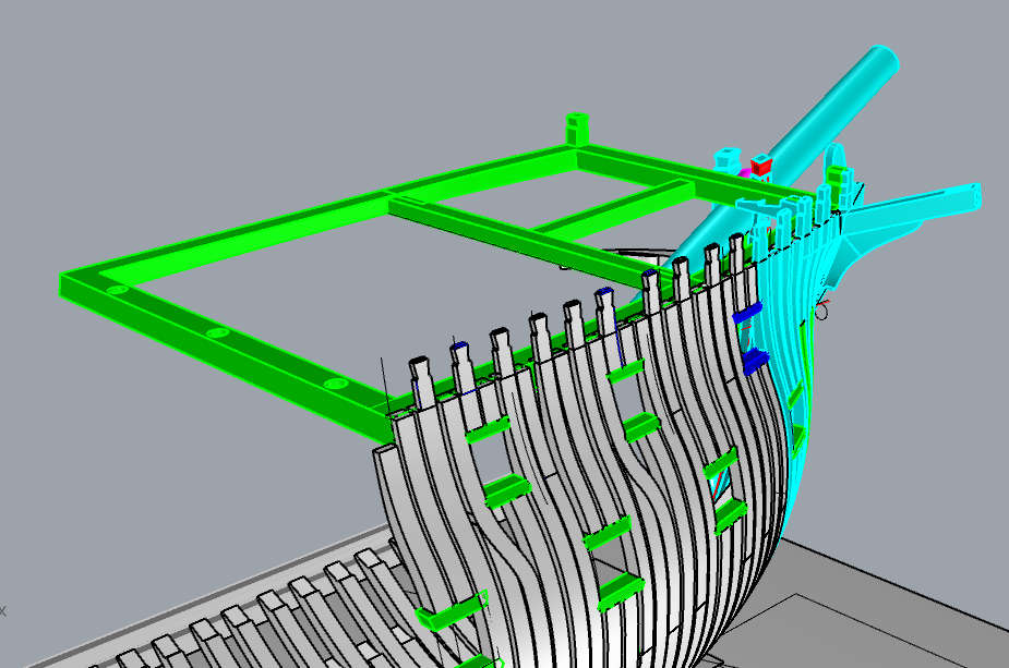
Hi, Liu has started assembling the cantframes. I suggested that he assemble the adjacent main frames first , then adjust the filling frame, and by the way, assemble the port cills too. This might be a completely new assembly method, or rather, a new sequence. Such an assembly sequence is based on the characteristics of CNC-machined components. Of course, with such components, even an average modeler could finish assembling such a complex POF model after a little practice. Anchor chock and port cills are supplied as finished products. However, I’ve also been working on a few ideas for jigs – specifically, using 3D-printed composite jigs that would let modelers sand square frames by hand quickly yet with minimal effort. This would make the processing costs much lower, thereby significantly reducing the price of the kit. As for the false keel, it’s true that 74-gun ships of that era should have had a double layer. But back then, I thought that overly thin components would be prone to deformation – especially horizontal deformation – which would be catastrophic. Maybe I’ll offer a suggestion: if needed, one can modify it to a double layer themselves.

-
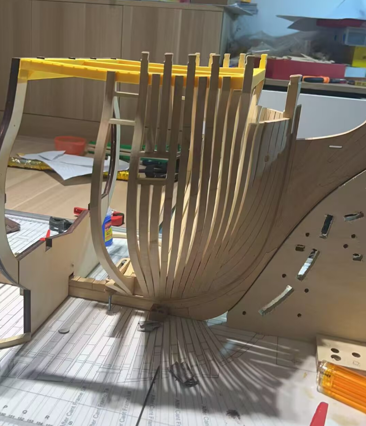
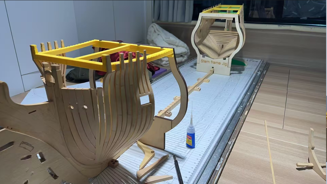
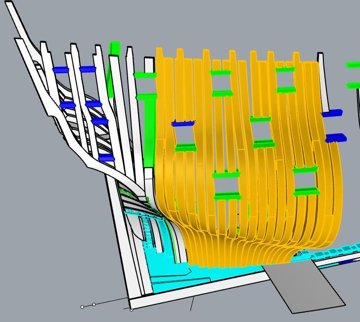
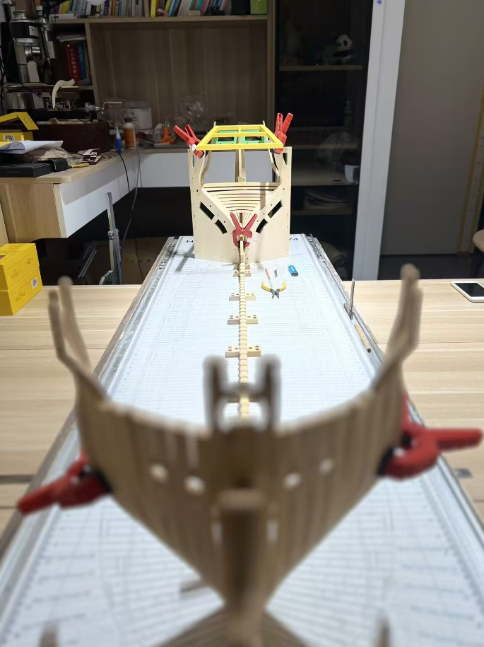
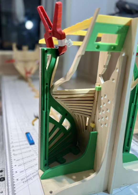
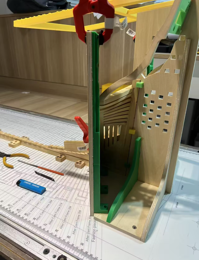
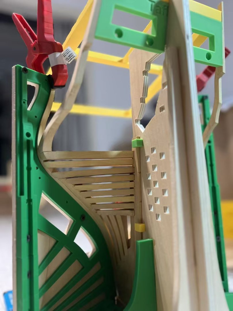
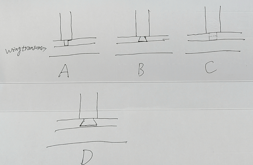
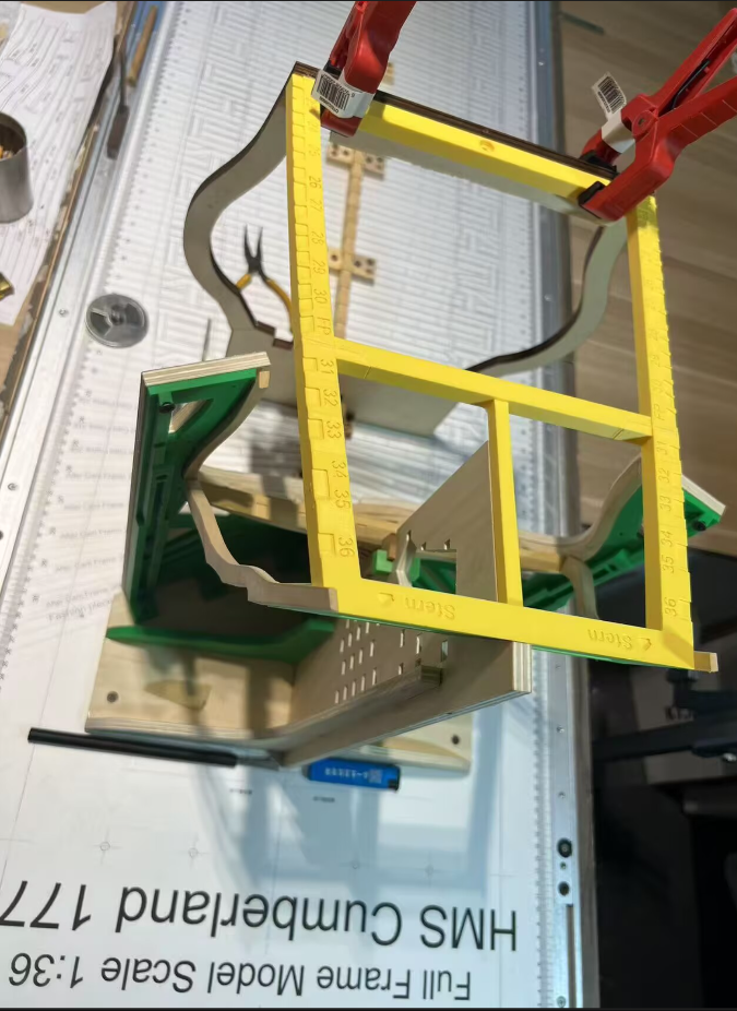
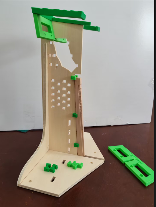
Hi everyone, Liu has completed the assembly of the wing transom, fashion pieces, and filling/deck transoms. Perhaps due to the bulkiness of the hull, he hasn't provided photos of the rear-facing perspective. However, I expect he will offer close-ups of this angle once the fashion pieces jig is removed. He used his own skills to assemble this structure, and his feedback is that the jig has a slight deviation and needs to be calibrated according to the drawings, while the wooden components have minor warping that requires on-site adjustments. I only made a 0.7mm allowance for the key transoms components. Next, he will finish assembling the top jig, after which he will start assembling the cant frames. Regarding the dovetail grooves on the upper surface of the wing transom, I adopted a simplified version of David White's "let down" method, though I first came across a comparative introduction to it in David Antcherl's book. Personally, I don't think the straight tenon of Type A is logical. When using real tenon techniques, one should either employ dovetail tenons or simplify them into hidden dummy tenons. The dovetail tenon of Type B is probably the more widely accepted structure, but my teacher's idea is similar to Type D. That is to say, it's not a direct dovetail tenon—since sharp corners are prone to damage, there might be a small section of straight tenon followed by a dovetail tenon. Given this, as someone obsessed with museum models, I opted for the simplified "let down" dummy tenon. Complete the support for the TOP Jig.
-
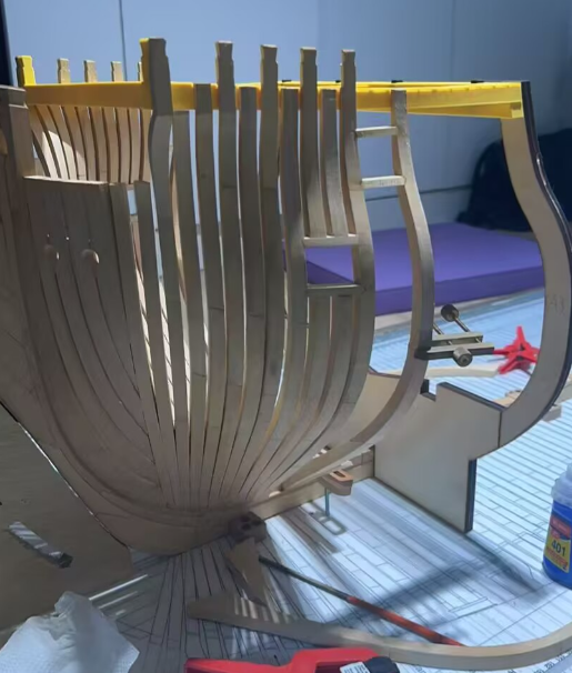
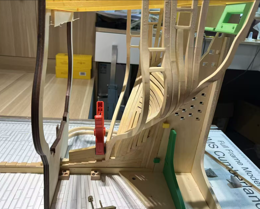
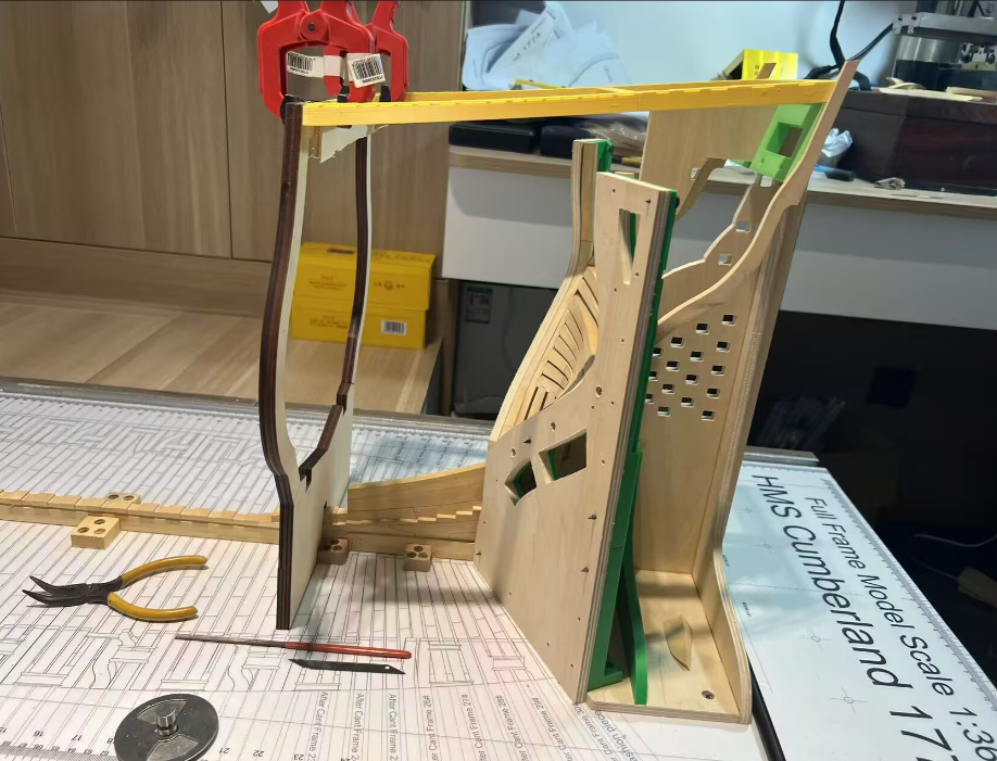
Liu started assembling the transoms at the stern, using his own methods and sequence. I didn't offer too many opinions, just reminded him to check the drawings and ensure symmetry and verticality. I have been worried about the accuracy of the assembly of the wing-transom, deck transom and fashion pieces, but now we can only wait for his next step of work. This process seems to be a test of whether the design and processing techniques I have adopted can enable an ordinary modeler without professional training to complete the assembly of such a complex tenoned structure, as well as the final result. Liu had previously completed a POB kit, but he had no experience in assembling POF. However, so far, it looks pretty good. The reason why I am so concerned about this key structure is that when I communicated with an excellent Chinese modeler a few years ago, he expressed doubts about this kind of structure of mine. He adopted Edward's method, which is a good scratch build method that has been repeated by many people. However, in order to avoid copyright issues or plagiarizing other developers, I need to design an entirely new jigs, processing techniques and assembly methods. Now I am also waiting to see if this new method works. My idea is to enable more ordinary modelers to complete such complex structures without requiring highly professional skills.

-
I just sent a courier package to the United States. FedEx requires the prepayment of customs duties, and there is a complex calculation formula for it, with the duty rate being approximately 10%.Fortunately, it is neither the 125% tariff from a few months ago nor 30% currently .
-
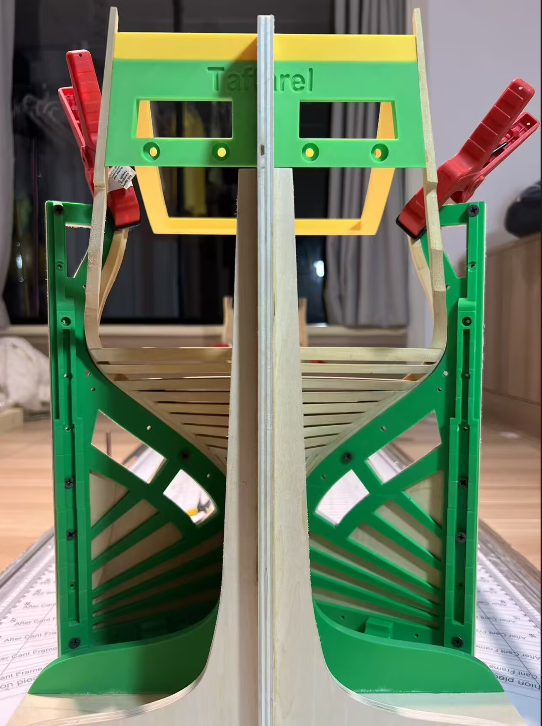
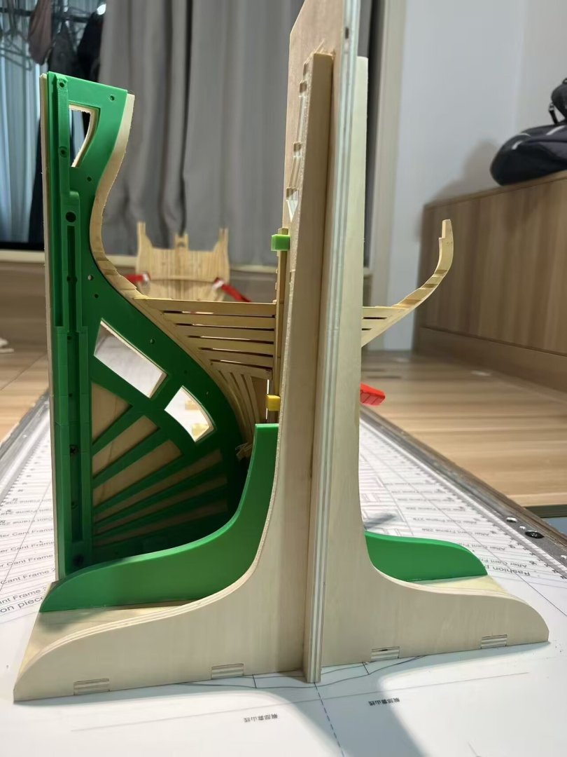
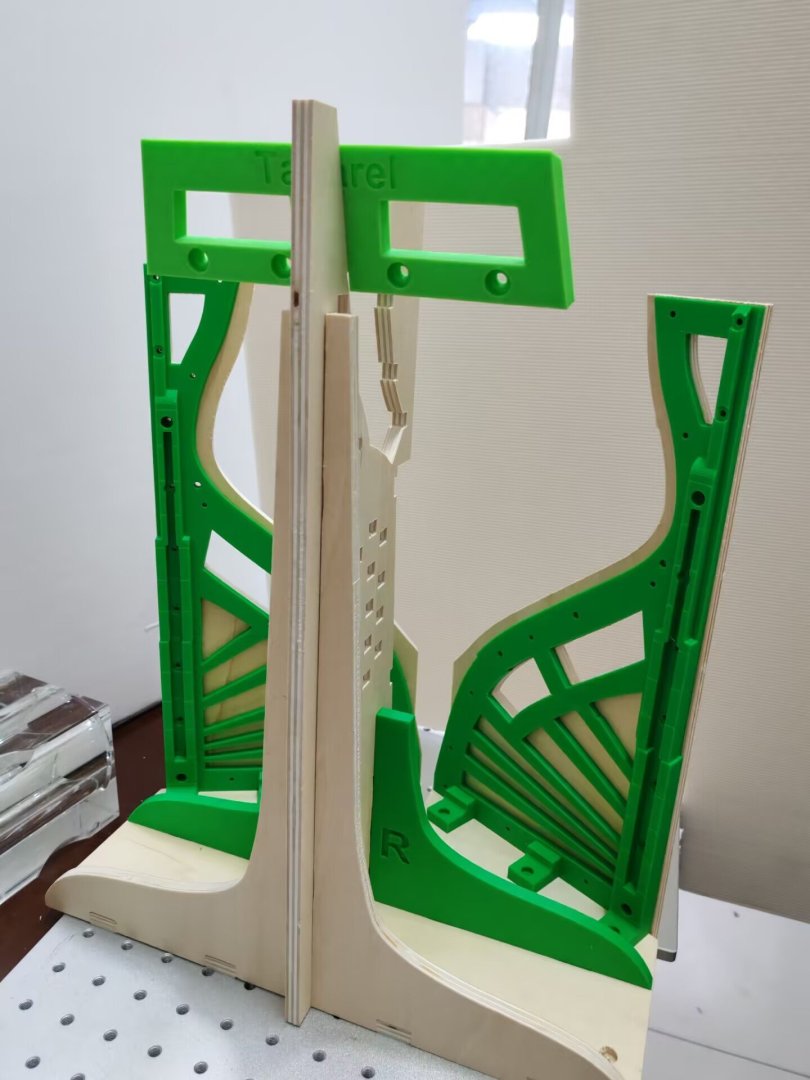
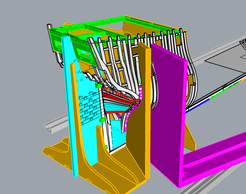
To better fit the structure of the kit, I have modified the fashion pieces jig and adopted a composite structure of plywood and 3D printing.The 3D-printed structure can well match the curvature of the frame's outer surface i think. Today, I have sent the complete set of frame jig to Liu, and he will provide his usage experience soon.

-
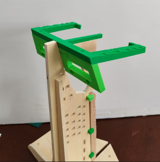
Hi! The first prototype of the frame jig, which combines 3D printing and plywood, will be sent to Liu immediately. He has been waiting for these components to complete his subsequent assembly work, and this will also serve as a good opportunity to verify the set of jigs. He will provide me with feedback afterwards. And stern.
-
Thank you for your attention; I think this project will eventually be released, whether it's a kit, full or semi-kit/ basic kit, or the drawings. However, first, this prototype needs to be completed, with the unreasonable designs addressed and the errors corrected. I know that it's impossible to avoid all mistakes; I can only try my best to do better.Secondly, my teacher, who has also participated in some of the design work, and I will discuss when and how to handle the drawings . In general, this project will definitely be presented to everyone once it's completed.