
HOLIDAY DONATION DRIVE - SUPPORT MSW - DO YOUR PART TO KEEP THIS GREAT FORUM GOING! (Only 13 donations so far - C'mon guys!)
×


Dan Vadas
-
Posts
3,261 -
Joined
-
Last visited
Content Type
Profiles
Forums
Gallery
Events
Everything posted by Dan Vadas
-
I've seen some Asian sites with ridiculous prices. Apparently they list them in Hong Kong Dollars and fail to convert to US Dollars, hence the huge "price". Danny
-
This one looks to be a reasonable price. It would be around $US50.00 plus postage from Australia. Danny
-
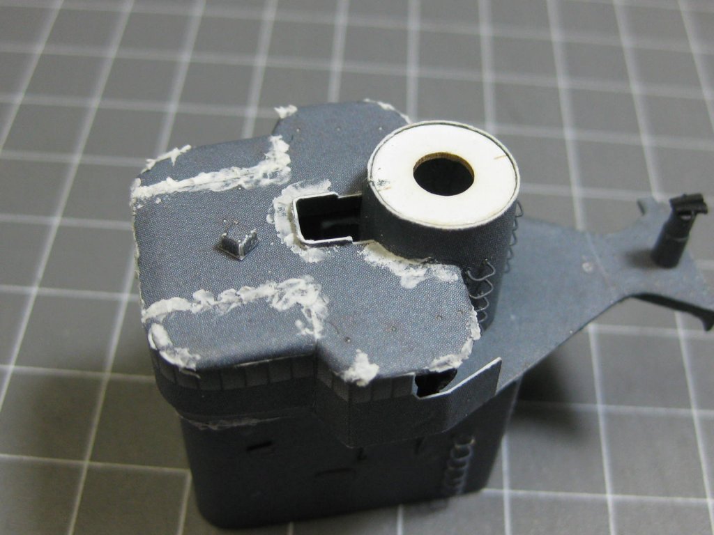
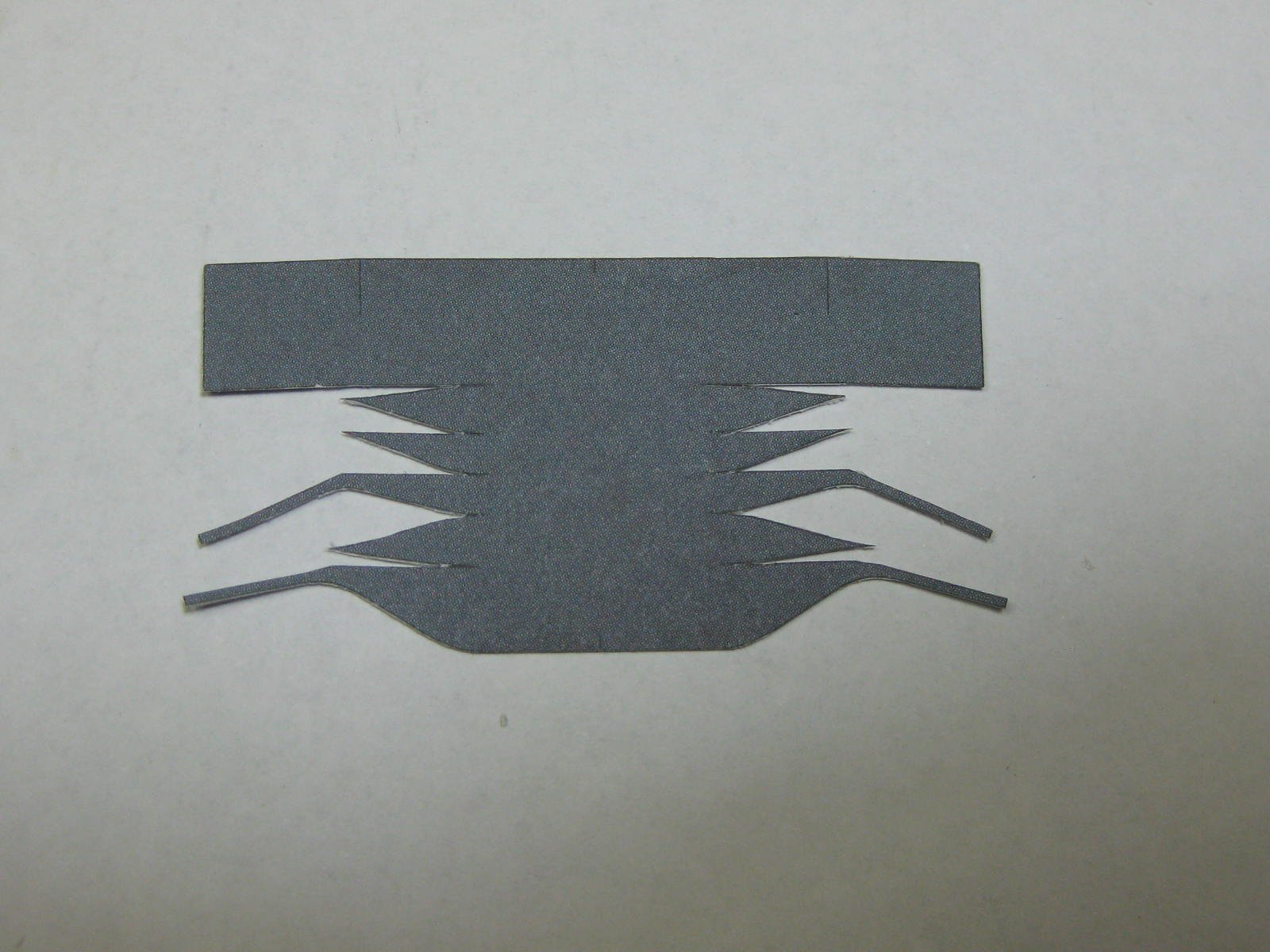
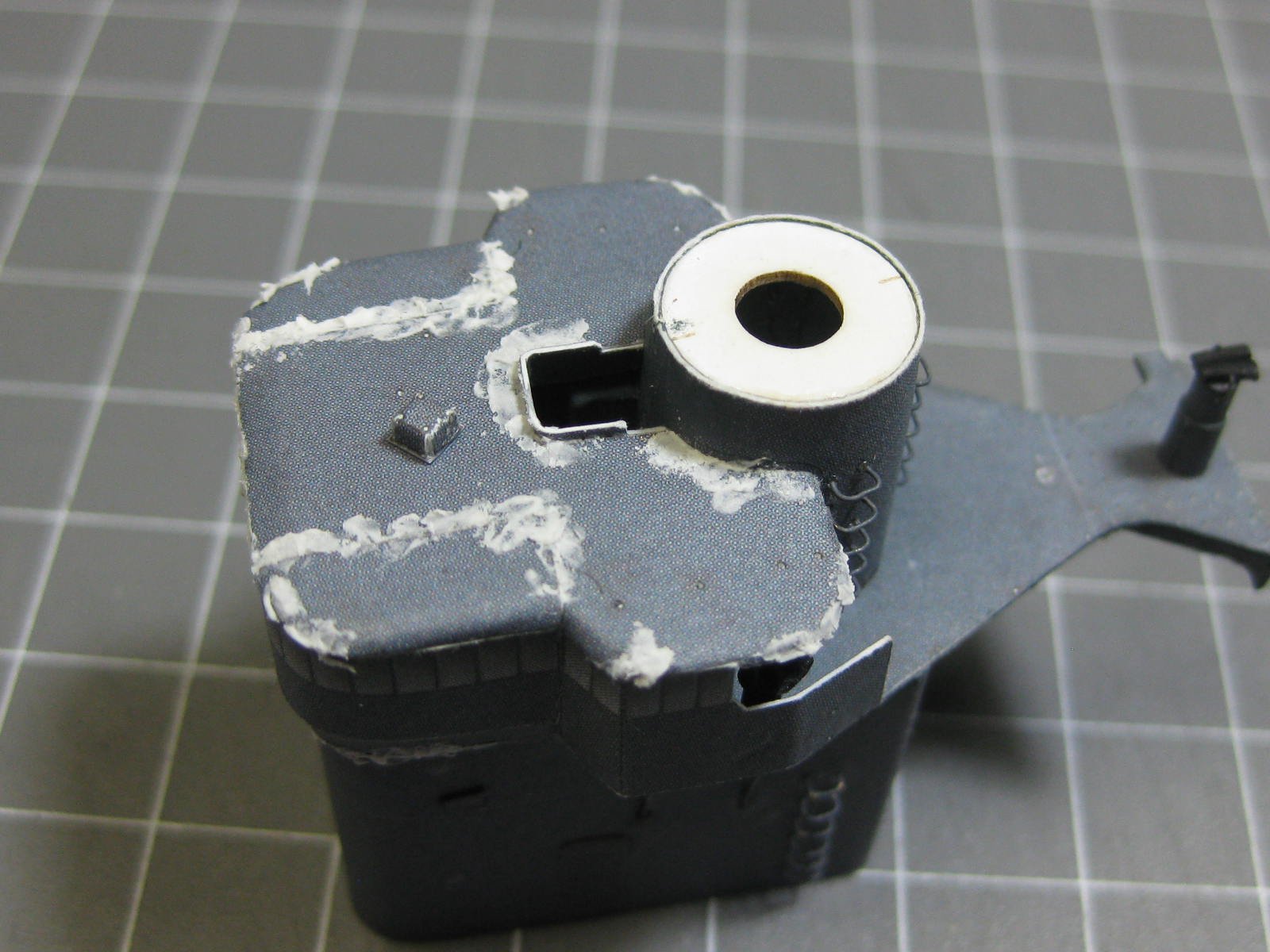
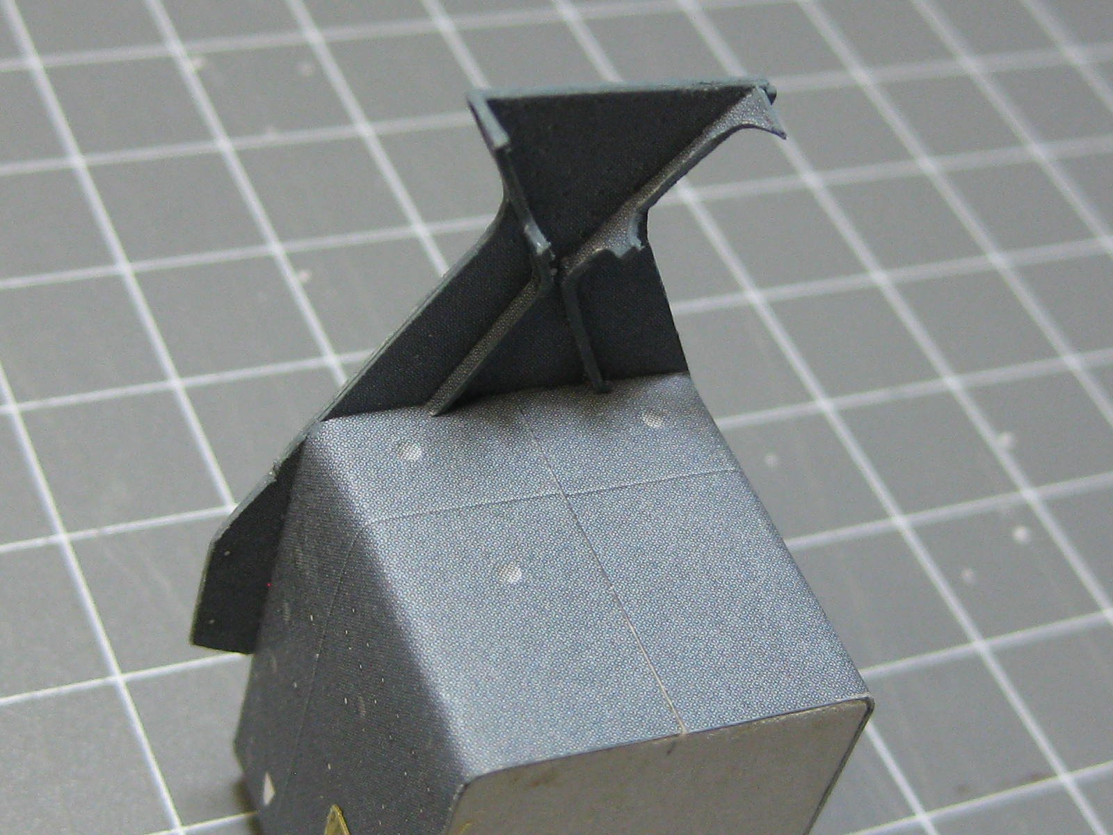
Thank you again Slog and Pat. Pat, Amatsukaze was completed in October 1940 - 15 months before Pearl Harbor. That makes it peace time in my book . Another Alien Invader - this time the Main Engine Room Vent. Here's the part after cutting out : And 3 hours later after gluing it together. No filler or paint has been applied yet, not much will be needed : Danny
.thumb.JPG.c5010c6033f336ff8df0b463cbffa50d.JPG)
.thumb.JPG.0a266bd7caeed14bc81118616d8f1c5d.JPG)
.thumb.JPG.ad9f9578154e51e39c35f9bfc3f06daf.JPG)
- 295 replies
-
- 21
-

-
- amatsukaze
- halinski
- (and 2 more)
-
Hi Miro, If you start a Build Log for your San Francisco (in the "Build Logs for Kits" forum) we might get an idea of your skill level. Then we would be better qualified to recommend a second model ship for you based on that. All the kits you are looking at require a high level of skill, and will take at least 2 or 3 years to complete so bear that in mind. BTW - it doesn't matter if you are a fair way into the San Fran. You don't need to have a shiny new unopened box on your bench to start a Log . Danny
-
Thanks Popeye. Next assembly is the Main Superstructure Base. I forgot to take any pics of the construction of the skeleton as I made it, but the pic below from the instructions is self-explanatory : The sides had a couple of interesting "whoopie-do's" that took a lot longer to get right than they look : The Funnel Base is next. Lots of care had to be taken to make sure the skin fitted properly. If I thought I was going to get a break from sanding by building a Card model I was very wrong . An hour's work sanding the correct angles in the top part : Bending the skin took another hour before I was happy with the fit : The skin received the usual strengthening tab at the join : Danny
.thumb.JPG.46fc13bfa5dd570de12b26beb719cdc0.JPG)
.thumb.JPG.e462f91b95c618df0a654f176bc5175a.JPG)
.thumb.JPG.8907098baa7b98ad4fbf1cbb544698b6.JPG)
.thumb.JPG.d07933adafa5c843b7ac687569de3759.JPG)
.thumb.JPG.d9f571a0a94da3aa6d5c66763a172426.JPG)
.thumb.JPG.ad62edfe24a1569e68c604970a7770c9.JPG)
- 295 replies
-
- 13
-
-
- amatsukaze
- halinski
- (and 2 more)
-
Thanks for looking in again Jan and Carl. I bought a few sheets of PE from Tom's Model Works suitable for IJN Destroyers : The kit Deck Reels weren't very detailed, so I only used the rolled tubes and replaced the discs and support frames with PE. There are 7 of them, of four different configurations : I spray painted them with Tamiya IJN Gray : Danny
.thumb.JPG.fe458632c08170fb2cdd3166e09b4a2a.JPG)
.thumb.JPG.06505f2d4801a99852b80d701f6a529f.JPG)
.thumb.JPG.d6cdc53de1374f0fc7f0ffeb8d55932c.JPG)
.thumb.JPG.f7dbc00a8bd3bea5cd22e4eb351be22e.JPG)
.thumb.JPG.a09e40b7720d9f2311b309ec383e515e.JPG)
.thumb.JPG.782aa110050e2a4cb8a31a62fd71a714.JPG)
.thumb.JPG.822317de5632dfdcb01dfadbd544acda.JPG)
.thumb.JPG.c453679275b697c09a9a79d2c37cf2d1.JPG)
.thumb.JPG.6deb53faf304f375dced6908545130f0.JPG)
.thumb.JPG.116a7947c736794aa373a616d1494043.JPG)
.thumb.JPG.5292098a1914bc45dd65d1967a0dcdc4.JPG)
.thumb.JPG.61398dcfd858f4ae29bab2b3e168d682.JPG)
- 295 replies
-
- 15
-
-
- amatsukaze
- halinski
- (and 2 more)
-
Yes, but I had to paint the red on the edges. Life rings are supposed to stand out, aren't they . Danny
- 295 replies
-
- 5
-
-
- amatsukaze
- halinski
- (and 2 more)
-
Thanks CDW, Cliff and Carl. Does this pic help Carl? Danny
- 295 replies
-
- 16
-
-
- amatsukaze
- halinski
- (and 2 more)
-
After applying the Dullcote. Sure enough, the touch-ups are almost invisible. They actually look 200% better in "real life" . Danny
.thumb.JPG.b7139dd5623cabc14fbe2b802cbb464b.JPG)
.thumb.JPG.165f4744a1eee2f115c0c0d9712d53cb.JPG)
- 295 replies
-
- 17
-
-
- amatsukaze
- halinski
- (and 2 more)
-
Not so fast Cliff. Check out THESE Monograms from Syren Ship Models to see if they will be suitable . Danny
-
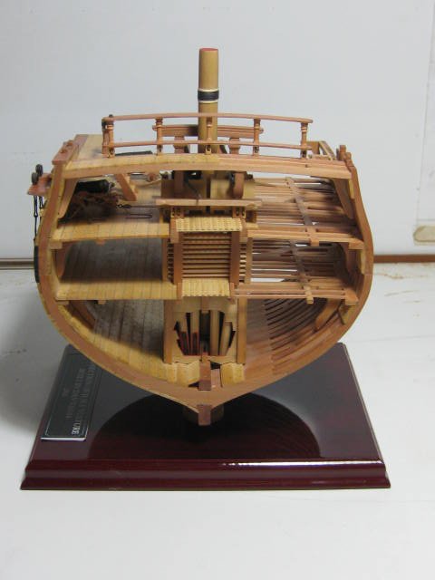
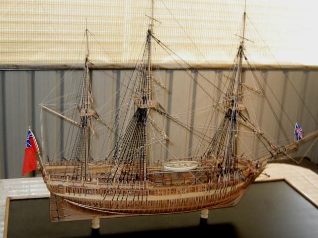
Or you COULD go the other way - build a full model AND a Cross-section of the same to show some of the interior detail that can no longer be seen after hull and deck planking : Danny
- 99 replies
-
- 11
-
-
- essex
- cross-section
- (and 1 more)
-
Thanks Ron. I noticed that you have a Card model of SMS Hegoland in the offing - good luck with her . I trust you will be doing a Build Log ? I've fitted the roof of the bridge. Some filler was needed on the seams. Here's how it looks before any cleaning up ...... MESSY : I use a narrow chisel point Xacto to remove the bigger lumps, and then a wipe over with a Q-tip dipped in Acetone to smooth it. The Acetone will remove some of the printing if it's over-used, so care must be taken : The final details to be fitted to the bridge were the PE Railings. Note the tightly bent ones around the two hatches. I drilled a hole for each leg and used thin CA wicked in with a cut-off needle to attach them. One of the few times I use CA . The railings I've got are longer than the ones indicated on the model, so some modifications are needed. For example, the two straight railings on the roof are one section of "standard" railing with an extra leg inserted into the middle with CA : And finally - a couple of pics of the finished Bridge after painting. It still needs a coat of Testor's Dullcote, which will make all the touch-ups virtually disappear : Danny
.thumb.JPG.6c7b7584ecae8d518a8cafa0bb0f1bd7.JPG)
.thumb.JPG.3f33147612bbe0a6e0b2d5f49020678b.JPG)
.thumb.JPG.4cbf57a3cb8c84cf40f8d86fe2f9fbfc.JPG)
.thumb.JPG.ecd2a97b1346cdaa08a045069f82b04d.JPG)
.thumb.JPG.acf844af10069390ecd141bd0e465494.JPG)
.thumb.JPG.b033a0bdf2f6ec5c005641ed3718b1bb.JPG)
.thumb.JPG.9ce7caf9f5c102085d51ca9dd13a75de.JPG)
.thumb.JPG.01121bd37fc3d0de7e48065942fb2503.JPG)
- 295 replies
-
- 21
-
-
- amatsukaze
- halinski
- (and 2 more)
-
I think this item is a small Range Finder (correct me if I'm wrong - the kit doesn't give any idea of what most of the assemblies are.) Small items like this are usually harder to make than large ones. This one is 3mm square : There are about 24 parts to the large Range Finder. I am very happy with the way this assembly has come together, just some minor edges to touch up : The roof of the bridge is curved so it has a ceiling and several ribs to form and support the top skin : I made a small error when trimming the edge of the roof to accept the walls, so I had to cut the walls into three pieces to get everything aligned properly. Two small tabs give extra strength on the cuts : Danny
.thumb.JPG.c287fd3bb104751b4f7f14d74d802b12.JPG)
.thumb.JPG.2f9c5ee5dc5ca9cbc255760cbbf8e6a3.JPG)
.thumb.JPG.e209aefce864575408e9c4c4db74531f.JPG)
.thumb.JPG.1f79ccac7c2c3f699ecc2ff41817a90f.JPG)
.thumb.JPG.e3ba60dca774c7a049cecbb1343cace7.JPG)
.thumb.JPG.feaf7f405c59c78cde71d9f7032bb092.JPG)
- 295 replies
-
- 19
-
-
- amatsukaze
- halinski
- (and 2 more)
-
That's for sure Cliff. It took me a little while to get through to Shipmodels, I don't know if things have improved in the last 5 years or so. The language barrier is another thing to ponder - I had to use Google Translate, which sometimes comes up with weird results . Danny
-
Thanks for the kind words Cliff . I didn't actually order the Trunion Caps. Shipmodels kindly threw them in for free, and also gave me 13 barrels but only charged for the 8 I ordered . It looks like they cast them in a mould of 14 (one was missing), so they gave me all of them. I think the next size down may be a bit small, although you could file out the half-hole for the trunion or file down the trunion itself. It's a bit hard to say unless you have both sizes to compare. The larger ones are hardly noticeable as being a bit big on the model. Danny
-
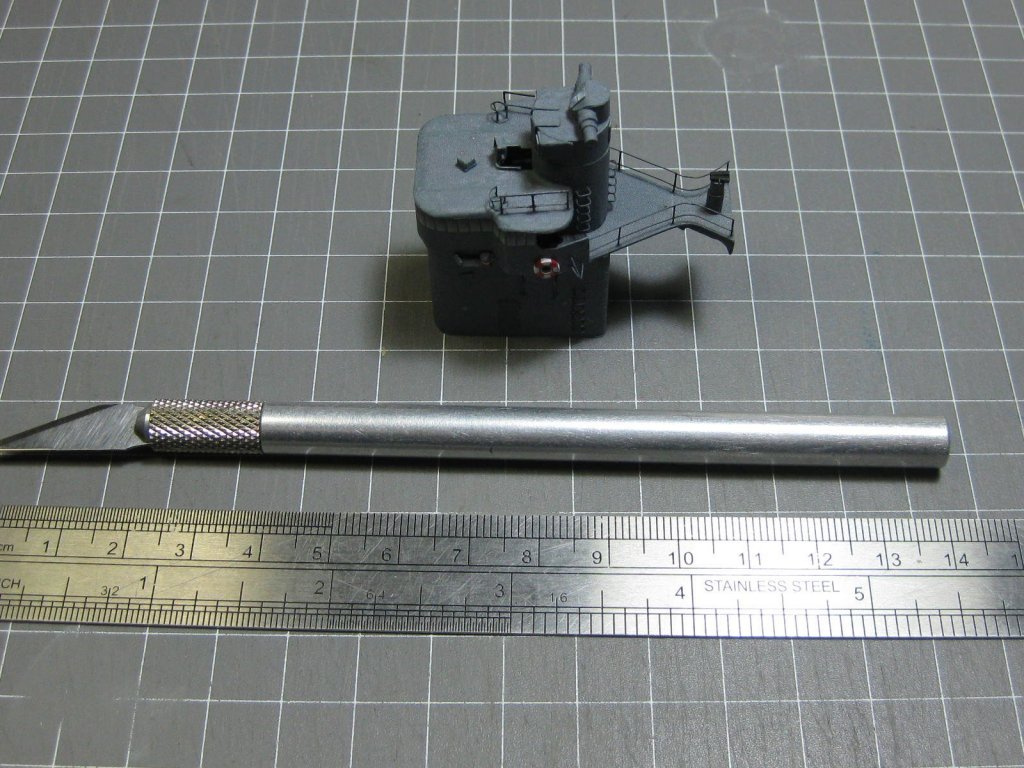
Yay . I'm into my 3rd day on the Bridge and still won't finish it today. So many small details to make - and most of them won't be visible later on . At least I know they are there, and it's all good practice. There are three different types of Binocular Stand to make. I guess this one incorporates a Bearing Compass? I've painted the step irons and PE doors. There's also some bracing under the overhanging part of each side - this is made from 0.3mm nickel-silver tube, the only stuff in that diameter that the Hobby store had (not cheap ). Here are some shots overall : And one last pic to give an idea of scale : Danny
.thumb.JPG.6f37423f3cf96b6467bedfc7b3602e44.JPG)
.thumb.JPG.45e39ee84d67dcacf355ab59421111fe.JPG)
.thumb.JPG.8eaa279d6f7ed20f585c37168c94f6ca.JPG)
.thumb.JPG.f0f48f078fb77b522dd81b3d50852c60.JPG)
.thumb.JPG.718a250ab50b28db2720fcf369b12589.JPG)
.thumb.JPG.e574fa61137c896fd373eb7e43d7a6e2.JPG)
.thumb.JPG.015a5e2b25372c097e95c60383da38b3.JPG)
- 295 replies
-
- 24
-
-
- amatsukaze
- halinski
- (and 2 more)
-
WHAT .......... ???? Hells Bells, I just spent 3 hours ............. Danny
- 295 replies
-
- 7
-
-
- amatsukaze
- halinski
- (and 2 more)
-
Yeah, I'm working on those but optically grinding them is proving a problem . Danny
- 295 replies
-
- 8
-
-
- amatsukaze
- halinski
- (and 2 more)
-
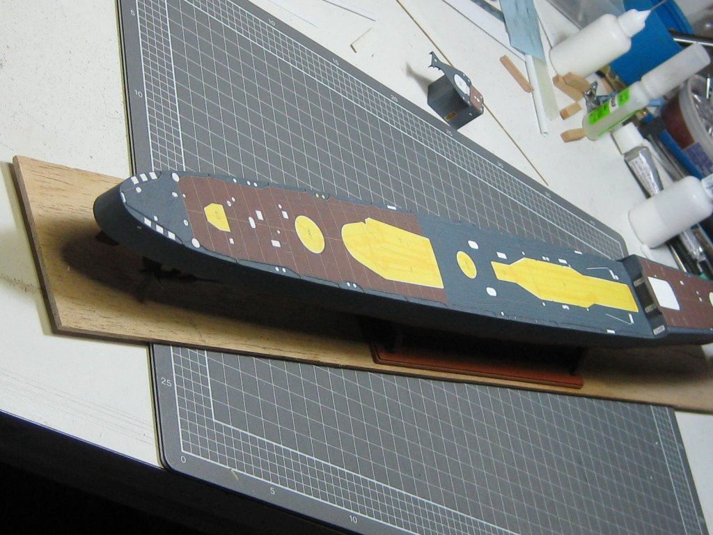
Thanks Slog, Pat and Popeye . Glue doesn't stick very well to the lacquer, so I masked all the areas where parts are still to be fitted and sprayed the rest of the hull with Dullcote. This pic also shows how far the temporary balsa base extends to protect the props and rudder : The upper section of the Conning Tower. The base of it is a "D" shape transitioning to a circular top : There are 12 tiny Step Irons on the lower part of the tower and 15 on the upper part. These are made from 0.2mm brass wire. I made a simple jig to fold them all to the right length : The conning tower features 8 sets of Binoculars on various types of stands. To make these tiny pieces (3mm long) I made another jig which consists of two pieces of tapered 0.5mm wire drilled into a block of wood at an angle : The first pair finished and mounted to it's base. The base is made by tightly rolling a printed piece of 0.2 mm paper until it gets to the required diameter of 2mm : Some pics of the conning tower with step irons and binoculars fitted. The steps will be painted IJN Grey later : Danny
.thumb.JPG.d088601aaaa61fb69db05c0997cc8822.JPG)
.thumb.JPG.2da4fa7a120f3f3df1f070a8c097cc0a.JPG)
.thumb.JPG.f3d7d3dd8a62da68fd5e67221fbf17bd.JPG)
.thumb.JPG.0b7fba3e5ef6ea875e4ac3b7ce33f234.JPG)
.thumb.JPG.4a57a7254391e5e12b792ef59fe78f18.JPG)
.thumb.JPG.a8670631e976bc7e6c836923a57e2950.JPG)
.thumb.JPG.62d7bc9e9ec61ebcf826c9c64bf2b760.JPG)
- 295 replies
-
- 19
-
-
- amatsukaze
- halinski
- (and 2 more)
-
Now that the Props are on (I should really have left them off until last) I needed to protect them from damage, so I made the stand. The supports under the hull are made from card in the shape of "I" beams. The base itself is timber. I tack glued the base to a piece of balsa a little longer than the hull as a temporary building board : I've filled the gap between the upper hull and deck and touched up all the grey. This time the colour was exactly right : I've also started the first superstructure - the lower part of the Conning Tower. I'll paint the PE doors tomorrow when I get some IJN Grey Enamel. There is more work to be done on this assembly : Danny
.thumb.JPG.1b823b6781d7f0070d36f8ada58c2e6a.JPG)
.thumb.JPG.9f16e2bb411e52bf865565f68fdc7ea0.JPG)
.thumb.JPG.8fa88b3c4f36fc42c6fab7a75f3d83f3.JPG)
.thumb.JPG.6804c0cede2189625f8af24adde3ad7c.JPG)
.thumb.JPG.0c8448ffea9b161139ea9a6fbf5a7d46.JPG)
.thumb.JPG.bb0dc2c4b049d454d47be5501f9dc26e.JPG)

- 295 replies
-
- 19
-
-
- amatsukaze
- halinski
- (and 2 more)
-
Jeff, I'd say the main reason they aren't "uniform" is because the edges of your timber aren't straight. Compared to the timber I use a lot of Kit planking strips aren't cut very well, indeed some are actually die-cut which makes for rather rough edges. I suggest you sand the edges of all your strips before using them. This isn't as difficult as it seems. There are basically two ways of doing it : 1. Stack about 6 or 8 strips together, tape the ends tightly together, and then sand them all at once. If you make a stack that's about the same as the width of a plank it'll be easy to control without the plank flopping around. Instead of taping you could glue them together for 5mm on each end if that makes it easier. 2. Make yourself a jig. You'll need a piece of ply or MDF about 6 inches long and two pieces of square slightly smaller than the width of your planks. Glue the two square strips to the MDF/ply base the thickness of a plank apart. Then you can slip a plank into the gap and sand away . Use a sanding block or stick with 150 grit paper. Danny
-
I filled the slight gaps in the prop cones and touched them up with a mix of Yellow Ochre, White and Black. I went over them several times with an almost dry brush to try and get a similar effect to the printing, and got it pretty close . Then I fitted the legs to the bearing housings and glued the props to the shafts. I've also made and fitted the Rudder. It has a piece of 1mm wire inserted and drilled into the hull for strength : Are they right John? I hope so, otherwise the pics in the instructions are wrong . Danny
.thumb.JPG.f5283182871559b3c57dc888a316bc8b.JPG)
.thumb.JPG.20a773449ff4dca8a71178ce40365f6f.JPG)
.thumb.JPG.458d84d5ef767571022a9ca3b014a7f6.JPG)
- 295 replies
-
- 19
-
-
- amatsukaze
- halinski
- (and 2 more)
-
OK, got that Chris - thanks. I guess these ones would be Cactus Petals ? Danny
- 295 replies
-
- 5
-
-
- amatsukaze
- halinski
- (and 2 more)
-
Recommendations For A Good Milling Machine
Dan Vadas replied to Thistle17's topic in Modeling tools and Workshop Equipment
Tom, get the Tilting Table. It can do from 0 degrees to 90 degrees and everything between. The Angle bracket is cheaper, but only does 90 degrees. You can bolt the Rotary Table to the Tilt table. Danny -
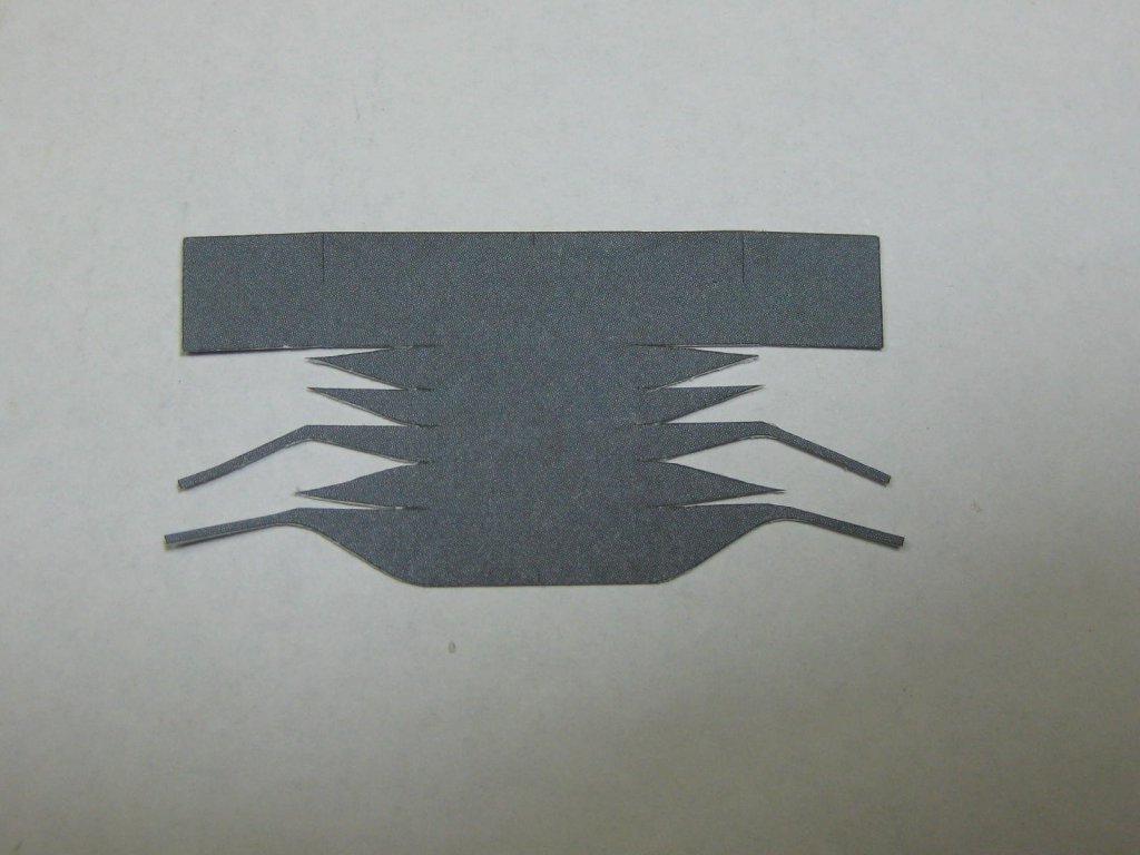
The Screws (Propellers) looked like being a fun build and they were. Here is the printed piece, it took some really delicate cutting to get the "spikes" bevelled. I used a single-edged razor blade, as it's thinner than a scalpel blade : I reshaped the cone "stick" I'd used earlier to hold the rolled piece : Here's the glued-up cone. Anyone who says he can make one of these without any filler or touch-up paint is either a genius or a liar : The end of the cone also has a small disc to align it with the prop shaft : The blades were pretty straight-forward to cut. I tapered the edges slightly. There are thin printed lines to follow when gluing to the cones : Danny
.thumb.JPG.033437d0bcf960a50139d1cf1ccac4c8.JPG)
.thumb.JPG.96ff9792737fa6375536d9eb9957f277.JPG)
.thumb.JPG.0cdf3e4fe29f480637d371aed667df42.JPG)
.thumb.JPG.c306a12f56cba6288af58231de8f981a.JPG)
.thumb.JPG.afe2431336ecc0220a407d3aaa1963e9.JPG)
- 295 replies
-
- 18
-
-
- amatsukaze
- halinski
- (and 2 more)
.JPG.674cac3d68fb644ecb4b73bf192ba432.JPG)
.JPG.93ec4a8a7d623bff5c7769bef9191a91.JPG)
.JPG.58711d59f0e5c54f78cce43682bc56d2.JPG)
.JPG.88b12f3bbc411ddb3afdcbbedaa37024.JPG)
.JPG.39c24b80c8c8288cefe20fef1e6f9ef5.JPG)
.JPG.621bb5304113528e253e3b17640c4279.JPG)
.JPG.6fa3ff3101745e72551175258bf318d9.JPG)
.JPG.036dadb73237ba69537733466adf4922.JPG)
.JPG.fd8e7b8cec99caac44f9dd6764247ea9.JPG)
.JPG.d10a3e4dca158d03aa97aa95c3412e95.JPG)
.JPG.5ef87ba99d62eb37177e416e5faa3025.JPG)
.JPG.2859b2248e2464ded4f02e8b72520234.JPG)
.JPG.e846c37ce9070abc1cb7d57534ecdc77.JPG)
.JPG.8114fe02aa3622616afd346b5bebbc1e.JPG)
.JPG.733d615605d0b3b9fc56d899d58257be.JPG)
.JPG.4a5f84700af065a66ea9ad4c1f54bd3f.JPG)
.JPG.9278b3e85cd707349e2ea34f7c5cbc31.JPG)
.JPG.5c8dd2699a6f4feb39d14d9d5e1b8bb7.JPG)
.JPG.95f650ea32f98be77c9de3040fb065f0.JPG)
.JPG.9f626e9d4c008163b06b3ee517f26367.JPG)
.JPG.f35ba9791e0fd150dc3c7731509aee62.JPG)

.JPG.d830936f363d2b9c3b8e2acc1a21de95.JPG)
.JPG.e3458b5b635169dd6fe8a1ee08927a82.JPG)
.JPG.4b67c00ccca800e3066d832304b9ebbb.JPG)
.JPG.35392d0d412872ff837e3109989911e7.JPG)
.JPG.05bc012a41a90ada463082c2b388dc82.JPG)
.JPG.2af731f8d07e76ed4c68ee453550bd3e.JPG)
.JPG.6fd4874439c0abf5a0000c74a04764c0.JPG)
.JPG.64c08a6dc578961a4a1b5167d6d3f3d2.JPG)
.JPG.b712fe71293837701c204241b1e611c5.JPG)
.JPG.3dc79701a4f2820b03f476c4d7470bb9.JPG)
.JPG.8c674094ee944a24982ab4d07f80885f.JPG)
.JPG.6e101f8dfc95560896212d752f469bae.JPG)
.JPG.c85d8ad5e7e90818a7450cd277e67630.JPG)
.JPG.4308e96f221fa354da31108d8ced3632.JPG)
.JPG.c9ed559f46a93b49d258253845fa7dd6.JPG)
.JPG.ed3e20ede711fe60061b6dbb33b80e52.JPG)
.JPG.7c0e0848ebc12c633229cafae34983c1.JPG)
.JPG.864be22f46f6af329aa82c57c7a9da66.JPG)
.JPG.5453b53211ec1f46b03716ef663b3b2e.JPG)
.JPG.59284d954f3c144ae6acdb12e8b97940.JPG)
.JPG.5fda3f85b36c3121a693c0da33fd0117.JPG)
.JPG.1bbebc7cfe4382dbfa5e57fd151b22a1.JPG)
.JPG.e97d990403740d58553847c66624c3b3.JPG)

.JPG.0f0de25da9c47f46f2fc85db2e4b9ff5.JPG)
.JPG.22f16854faf9b9cc99dd73bc81dbbc4c.JPG)
.JPG.1e833c9fabf3b947719906b7d288a5cb.JPG)
.JPG.119507cc29f3e198b8053e81e13502b5.JPG)
.JPG.aef5132f90aaedd12c6ba4b32b145f5a.JPG)
.JPG.fe357f52766813f77b8a8180a386eee9.JPG)
.JPG.2b2d9f9c2ef5a6af2477718b6fb213e5.JPG)
.JPG.9e2fdbe87d342790f6beafd5471476d5.JPG)
.JPG.4beedad84d4a1ad44ec64e15bc5b0eb0.JPG)
.JPG.b20ba5a3b727d133aba61a1fabf15f69.JPG)
.JPG.a57169393cbee623b7bbd3f7c309883d.JPG)
.JPG.8aa8629fcf05af5040090ee06472ac1e.JPG)
.JPG.fb0f2ef1e1bd118965b2f2ade3fb21c5.JPG)
.JPG.34adef416bf990e83cf381d0ccf818c5.JPG)
.JPG.ee32bdea1edffca3fdd6ad9cfccefd51.JPG)
.JPG.6a619318680c2d289b8ba7de9f36955d.JPG)
.JPG.110ef3c99f9ac9f2fb3aabb1f29624de.JPG)
.JPG.c7b6fd181978240320398dfa93d1aac5.JPG)
.JPG.ec1bb9565c7ba9c89bc35d140ceaf8d5.JPG)
.JPG.6ab08a07bf9ef25141e51d3e7ba4a8c4.JPG)
.JPG.cabc11b694ee2c4fcd9060dc923fb6be.JPG)