Dan Vadas
-
Posts
3,261 -
Joined
-
Last visited
Content Type
Profiles
Forums
Gallery
Events
Everything posted by Dan Vadas
-
Very well done indeed Grant, and also well done on some of the solutions you came up with in constructing various pieces . Welcome to the Scratch Building Club - I'd reckon you won't be doing too many Kits from now on . Danny
- 456 replies
-
- 6
-

-
- finished
- bomb ketch
- (and 2 more)
-
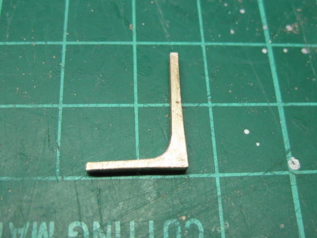
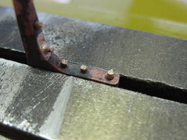
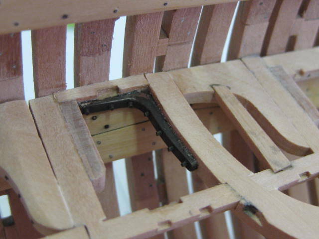
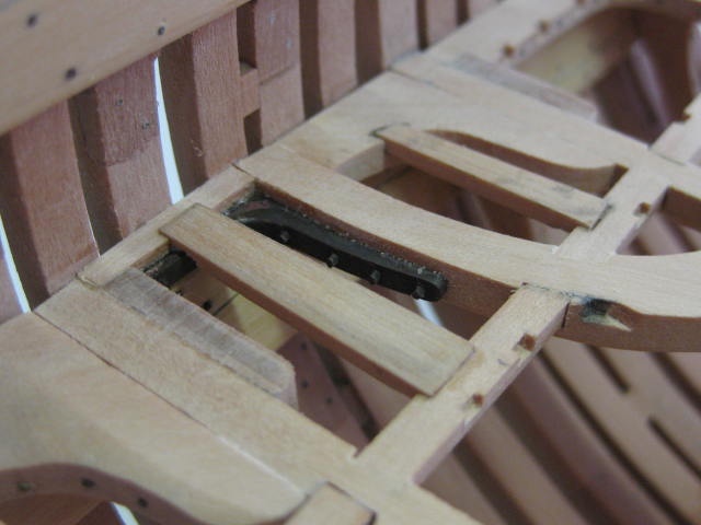
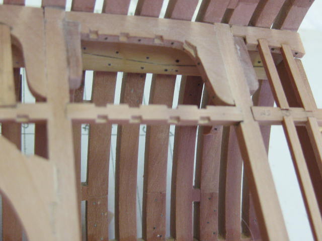
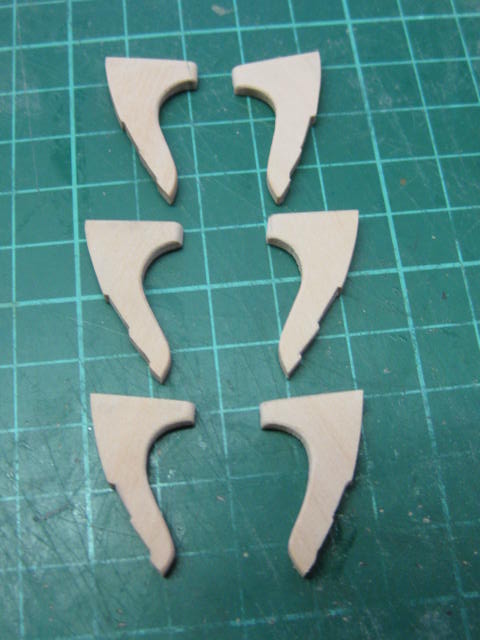
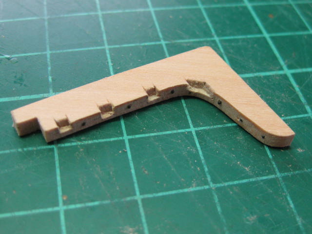
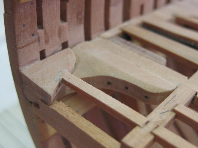
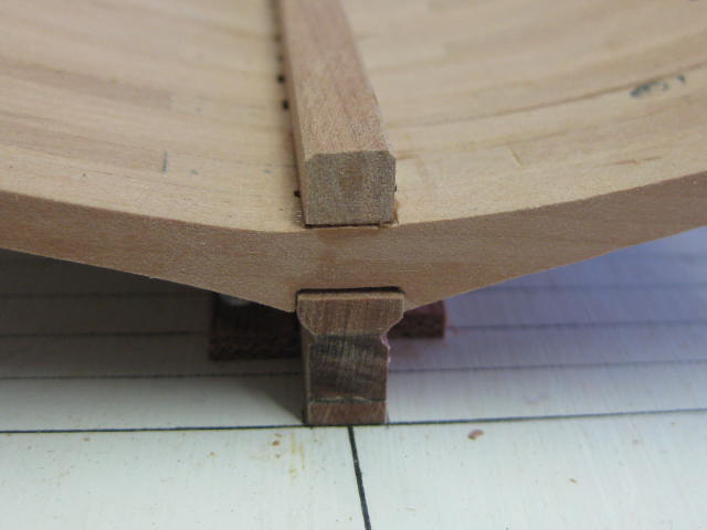
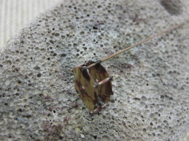
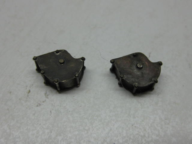
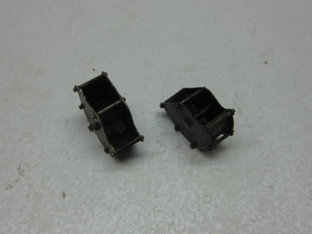
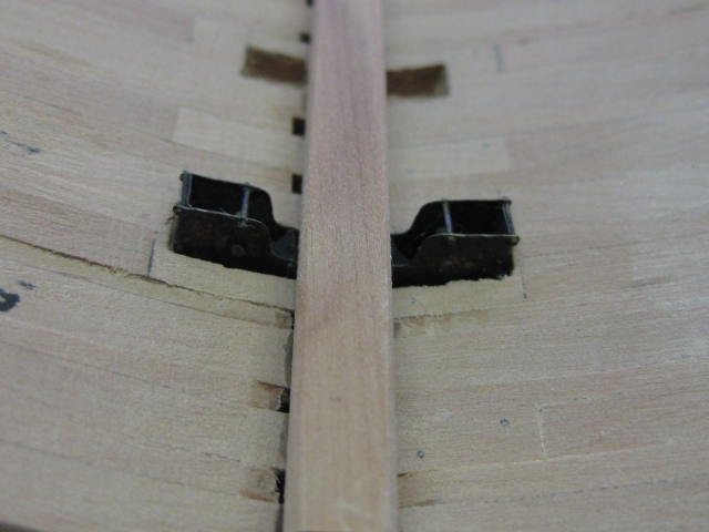
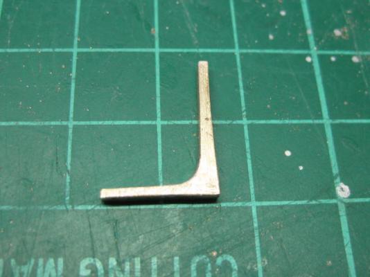
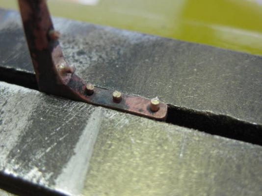
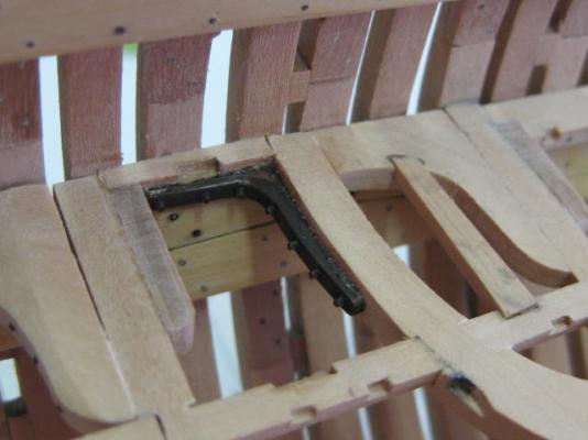
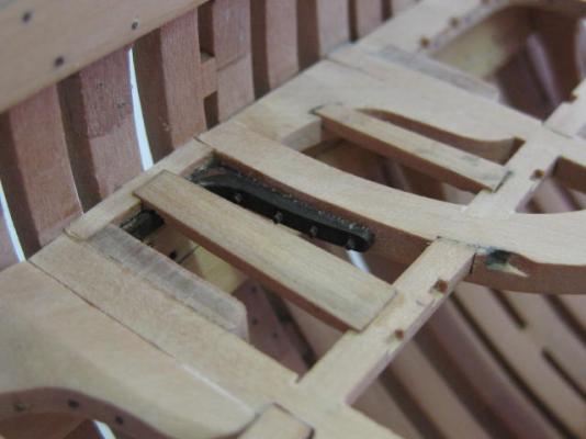
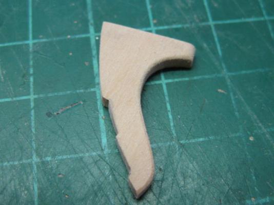
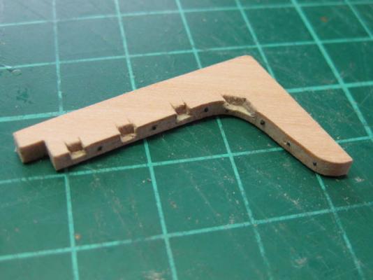
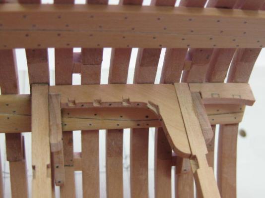
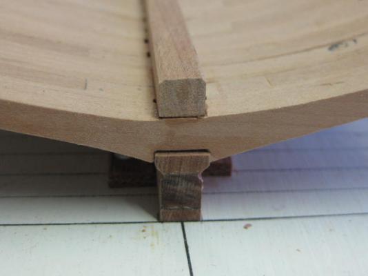
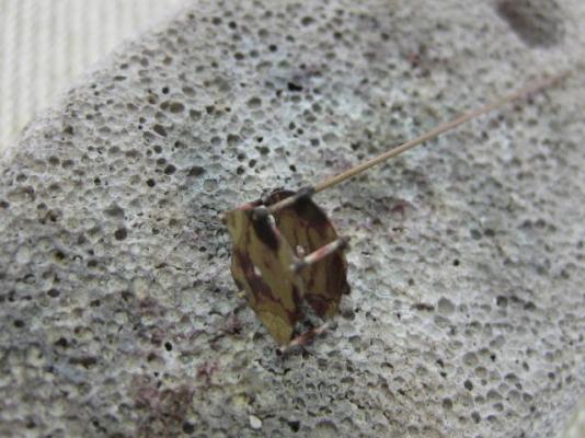
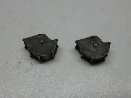
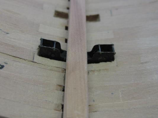
..... continued. An interesting little piece of "iron" work is a pair of Iron Knees, used to brace the Beam Arms. The pics should be self-explanatory : Danny
- 268 replies
-
- 32
-
-
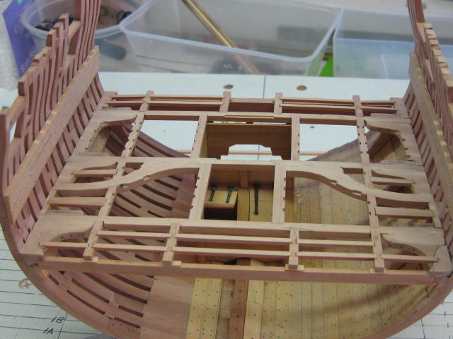
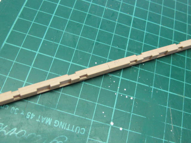
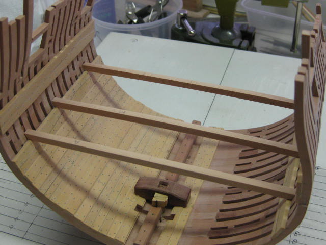
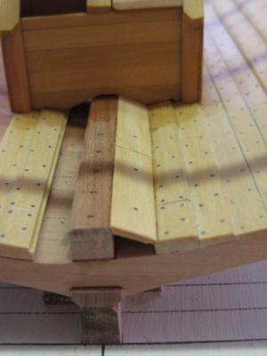
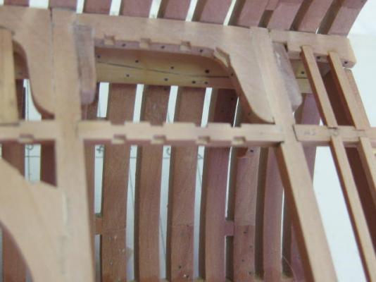
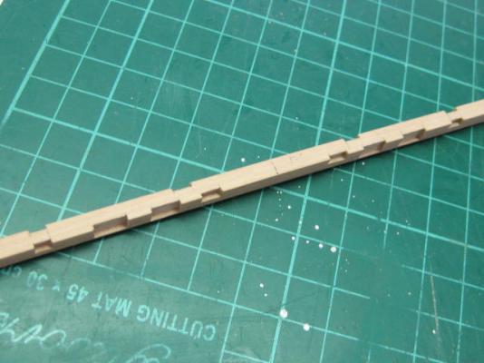
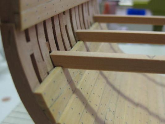
A pic I forgot to add in the last update - the Limber Boards, which cover the limber channels to stop them from getting blocked with ballast etc : Now the well is finished it's time to do the lower deck framing, starting with the Hanging Knees. There are only 6 to make for each deck. These need to be individually shaped to fit the internal timbers, even in this relatively straight section of the hull : The Lodging Knees are of varying shapes and sizes. This is the only one that would be the same as in the rest of the ship : At the Deadflat, which is one frame aft of the forward part of this model, is a pair of Opposed Lodging Knees. The hanging knees in the forward part of the ship are forward of the beams, whilst those in the after part of the ship are behind them. Therefore the need for a transition from fore to aft with the lodging knees. Because of the area I'm using for the cross-section I can only show half of the forward (upper) knee : Next come the Carlings, the longitudinal framing timbers. These are of various widths, depending on their functions. The "standard" ones are 6" wide, those alongside the hatches are 7 1/2". I've notched all the carlings for the Ledges, some of which are already fitted : Continued in next post .....


- 268 replies
-
- 29
-
-
How would you improve your Byrnes tools?
Dan Vadas replied to Keith_W's topic in Modeling tools and Workshop Equipment
Excellent idea Keith . Changing blades, particularly holding the axle, is a bit of a pain with the saw. I tip the saw on it's side and use a "dedicated" pair of small vise grips (set to the right tension) to hold the shaft. Your invention would certainly make life easier . Danny -
Hi Grant, Nice trick on gluing up the steps . Chuck's Monograms look the duck's guts - wish he'd have brought them out a couple of years ago . Danny
- 456 replies
-
- 6
-
-
- finished
- bomb ketch
- (and 2 more)
-
Funny thing Cathead - I had exactly the same idea as your Proposal when I first made my own Index and posted the "How To" above . It's certainly a good idea (in all modesty ), and quite a few builders have adopted it so far. Danny
-
Thanks all for the comments and Likes . First off, it's not a dumb question at all - there's no such thing on this site . In answer, Vulture's Main Mast Step is the only one moveable as the positions of the Fore and Mizzen Mast make them impossible to adjust. However many other ships had one or both of them moveable depending on the shape of the frame timbers surrounding them. Some ships had the Mizzen Step on another deck altogether. Danny
-
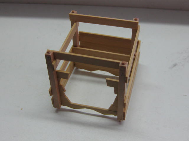
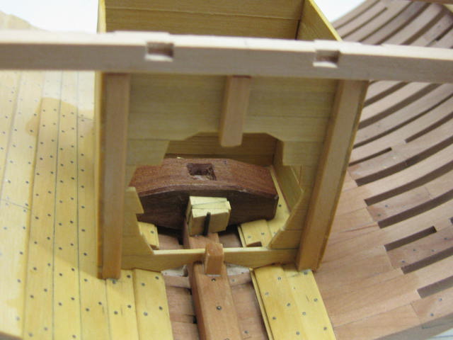
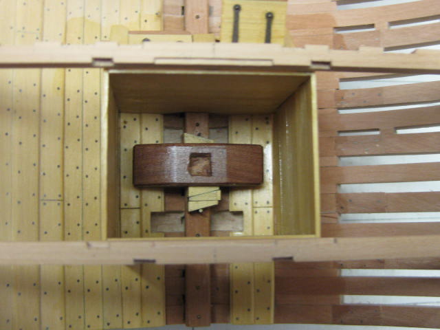
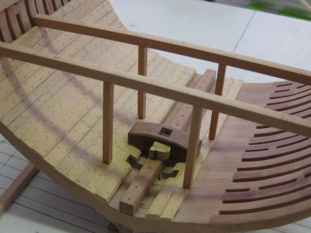
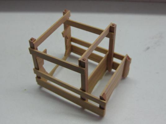
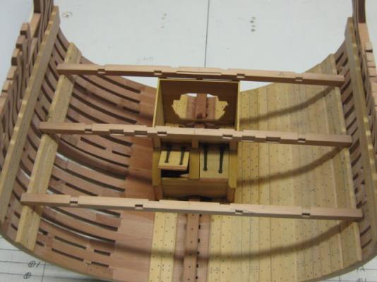
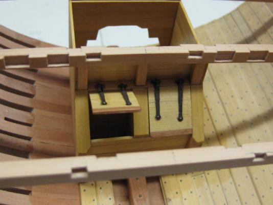
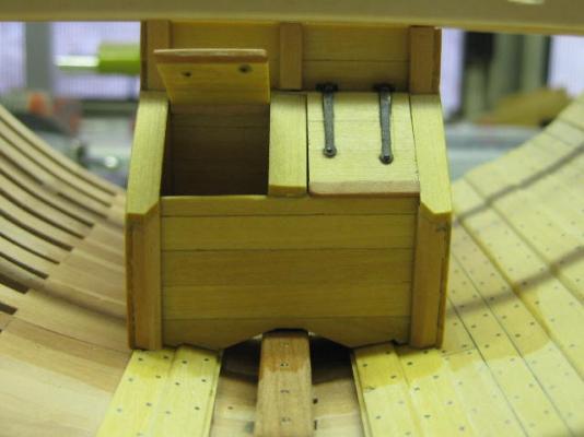
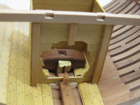
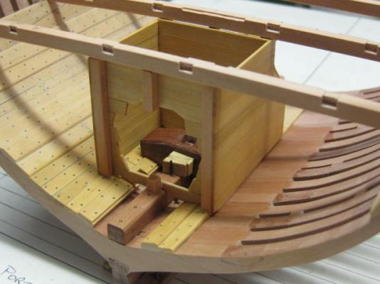
My construction of the Well and Shot Locker differed somewhat from my previous attempt in the full model of Vulture. This time I used the previously made lower deck beams as a reference, which resulted in a better fit all round. First I temporarily fitted the corner posts, spot-gluing the beams above them into position on the deck clamps (no glue between posts and beams or floor). Next I cut and fitted the lower strakes of planking to stabilise the bottom ends of the posts, and also tempoarily glued braces under the beams to get the top ends square : Then I removed the structure from the hull and completed the planking, removing the upper braces as they got in the way. The lids and hinges were added, and I gave the well a coat of Minwax Wipe-on Poly. Then I permanently mounted the assembly : I left a large cut-out in the aft end of the well to show the pump tubes and mast step : Danny


- 268 replies
-
- 33
-
-
How would you improve your Byrnes tools?
Dan Vadas replied to Keith_W's topic in Modeling tools and Workshop Equipment
I use the same as Rusty. Danny -
Thank you George, Greg and Robin. Robin, I used the treenails for ease of fitting. In reality they were mortised the same as the tops of the stanchions, but as this isn't visible I went the easier way . Danny
-
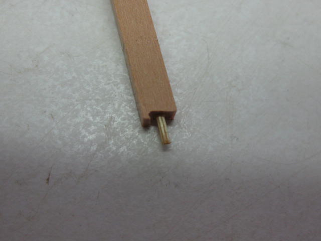
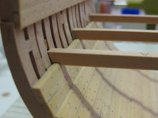
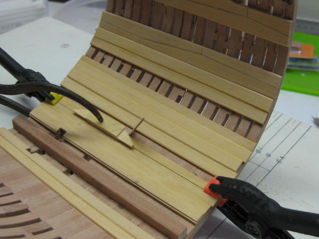
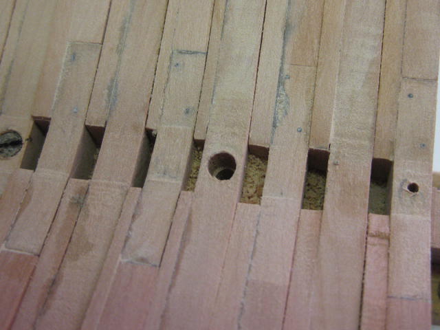
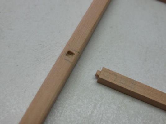
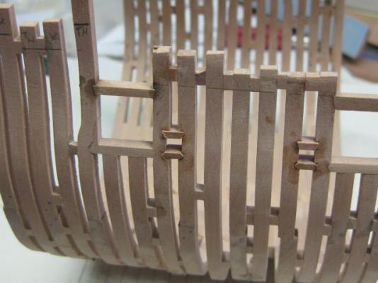
They're pretty much the same as the wood in your Echo Cross-section Maury . The stanchions for the Well are mortised into the underside of two of the beams : The bottoms of the stanchions are shaped to fit the limber strakes, and I've used 0.8mm treenails to locate them in position. The beams are only spot-glued into position at this stage, as they and the well will need removing again after I get the first few side timbers fitted to the well stanchions. I'll build the rest of the well and shot-locker on the bench before re-installing the assembly : All the mortices for the Carlings, Beam Arm and Mast Partner have been cut into the beams : Danny


- 268 replies
-
- 29
-
-
The three Lower Deck Beams are 8" wide x 9" deep, and have a round-up of 3". I've made them from Swiss Pear : The beams are "let in" (i.e. notched) to the deck clamps by 1" : Danny

- 268 replies
-
- 27
-
-
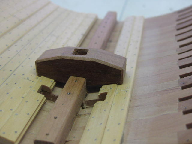
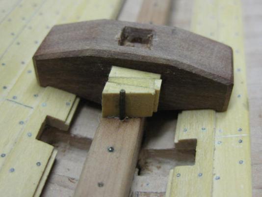
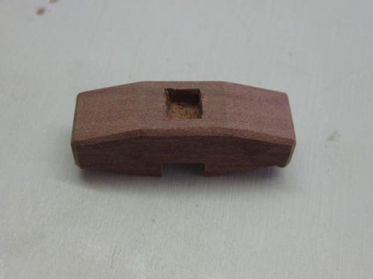
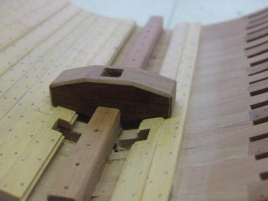
Thanks guys . Don't hold your breath waiting Pat - I don't have enough chain links to go round . Enough . The Mast Step isn't actually bolted to the keel, to allow the mast to be raked fore or aft as the need arose. Instead, it is held in place by means of wedges which are anchored by a 1 5/8" steel pin on either side : Danny
- 268 replies
-
- 25
-
-
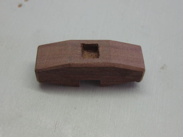
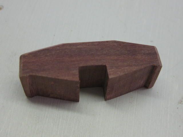
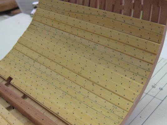
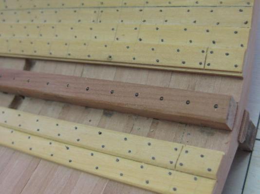
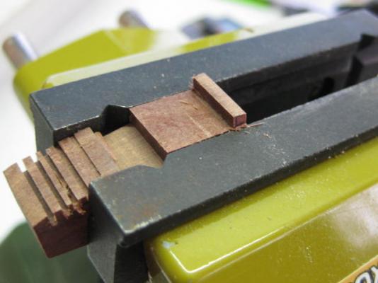
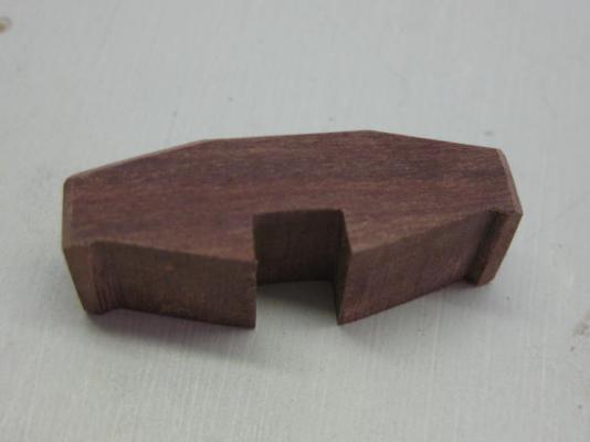
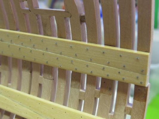
Thank you for the comments Greg, John, Albert, Neale and Druxey - much appreciated. Thanks for the clarification Druxey . Treenailing has finished for a while - there were about 750 in this section. I used 1 1'4" (scale) "nails" in the thicker timbers, and 3/4" in the Footwaling. No finish has been applied yet : The Keelson is bolted through the Keel with a Lip Bolt to each frame : The Mainmast Step is substantial - 1'10" x 1'8" in section, and 5'3" long. I cut and chiselled the under face to fit the Limber Strakes : The completed step. All edges are chamfered : Danny
- 268 replies
-
- 29
-
-
I have no idea how good or bad that kit is - better ask someone who has made one. Danny
-
Nicely done Maury. I particularly like the contrast between the Holly and Pear you have used for the planking - it's made me want to do the same for my Vulture Cross-section, except I'll be using Castello instead of the Holly (I don't HAVE any Holly ). Danny
-
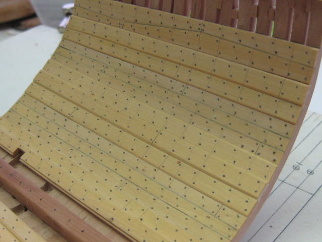
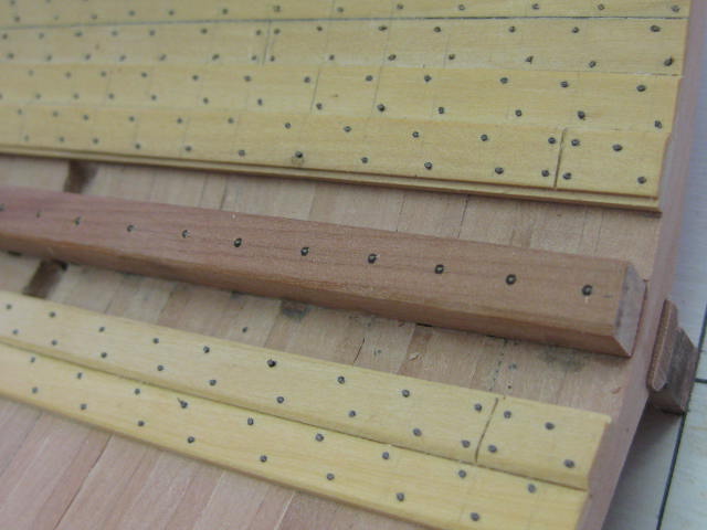
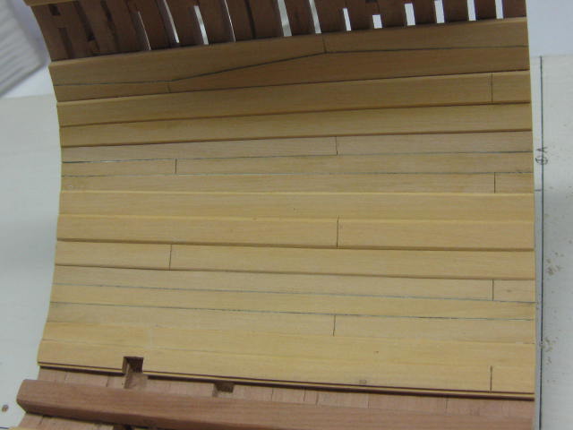
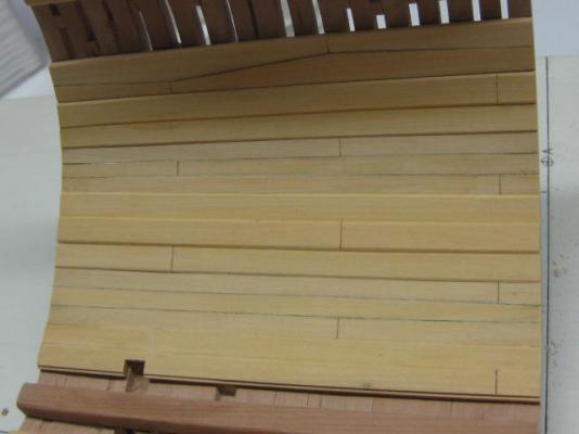
Thank you all for the kind comments. The Internal Planking is completed up to the level of the lower deck. I'm using Castello Boxwood for all the planking. This pic shows the lower and upper Deck Clamps. These are in "Top and Butt" configuration, sometimes referred to as "Anchor Stock Planking". The clamps are 4" (scale) thick at the top, thinning to 3" at the bottom of each pair. They are 14" wide at the widest point, tapering to 6" at the narrowest : More of the "special" planks. Starting nearest the keel is the 4 1/2" thick Inner Limber Strake, followed by the 3" Outer Limber Strake. Next set is the "Thickstuff over the floorheads" - the central strake is 4 1/2" thick and the two either side of it are 3". Further up are the "Thickstuff at the first futtock head" which are the same thicknesses as the previous set. I'm laying the first of the 2" thick regular "Ceiling Planks" in this pic : All the port side internal planking completed. The starboard side only gets the Limber Strakes and Deck Clamps : Treenailing has begun. I'm using 0.55mm bamboo which has been stained black : Danny

- 268 replies
-
- 34
-
-
Very nicely done Grant. The only thing missing on the guns is the George III emblem . Also known as a Timberhead - an extension of the frame below it. Danny
- 456 replies
-
- 5
-
-
- finished
- bomb ketch
- (and 2 more)
-
Thank you George . There's more .... I've cut out the recesses for the Chain Pumps and Elm Tree Pumps : And also fitted the Keelson : Lastly, I've made the Chain Pump Inlets using the pieces from the PE set supplied by Admiralty Models. These are probably the last of these available as the set has been discontinued and were graciously supplied by Greg Herbert from his own left-over supply. 0.5mm brass wire was used as the "bolts", and the assemblies blackened : Danny

- 268 replies
-
- 36
-
-
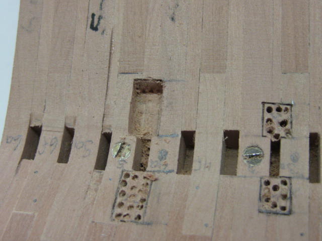
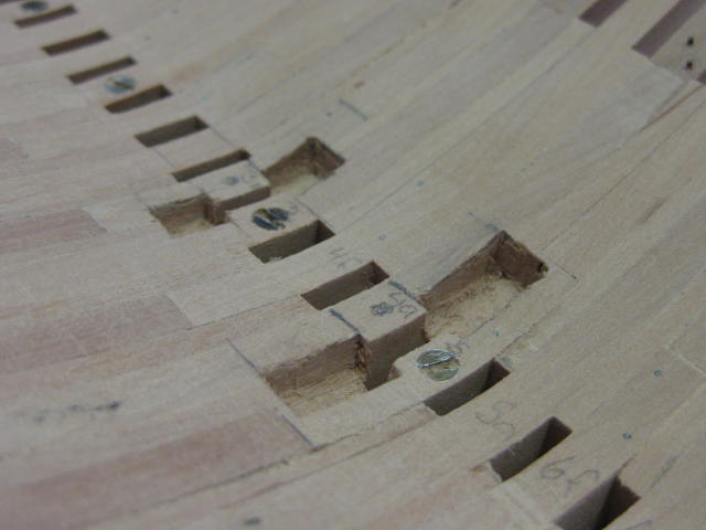
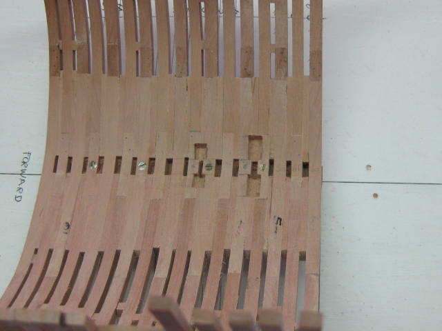
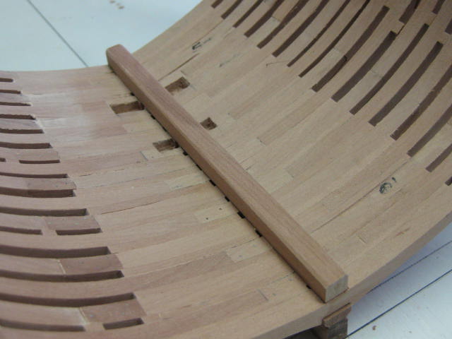
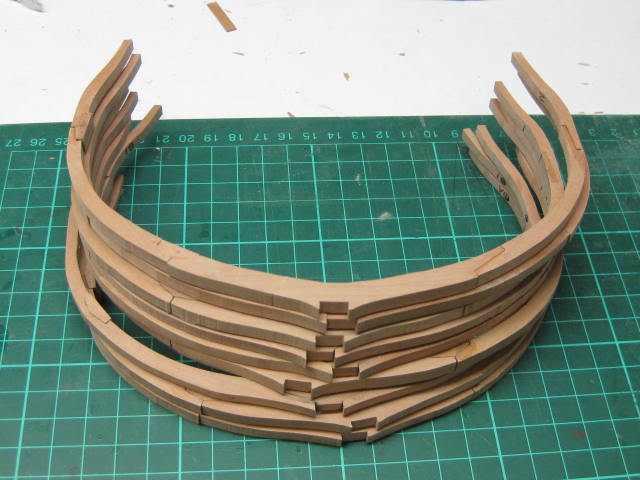
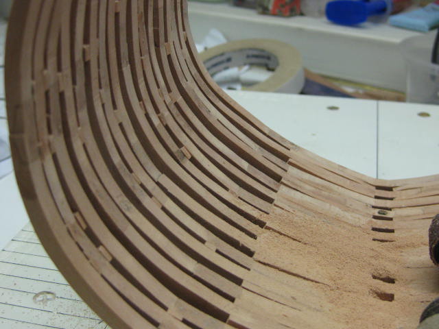
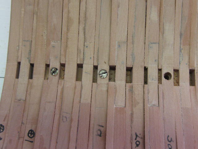
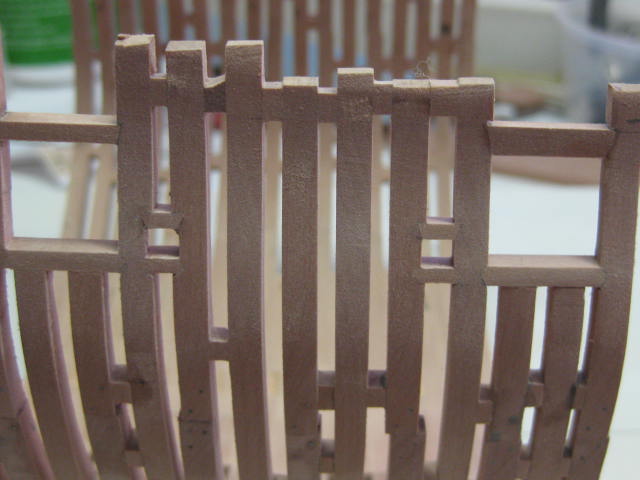
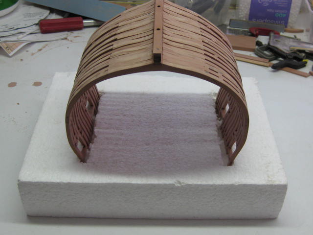
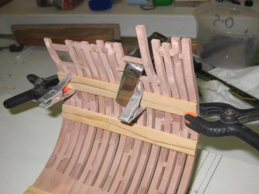
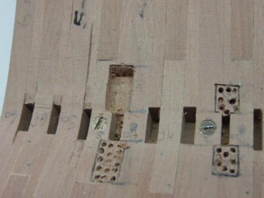
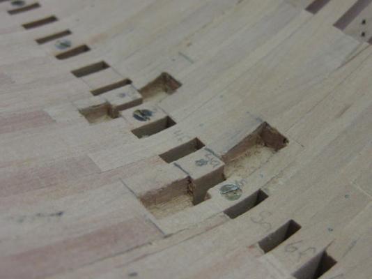
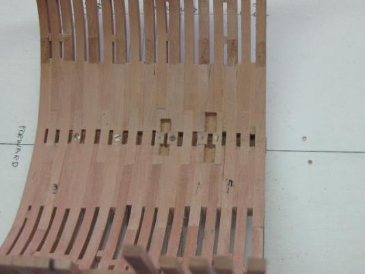
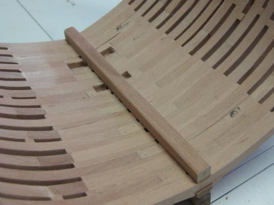
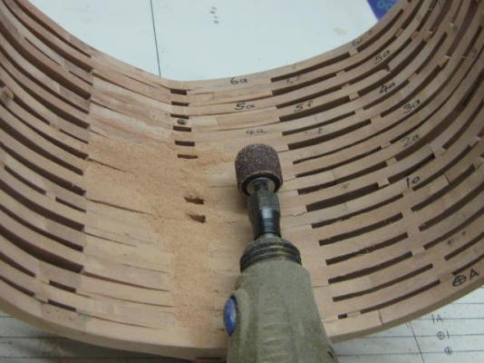
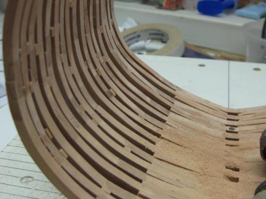
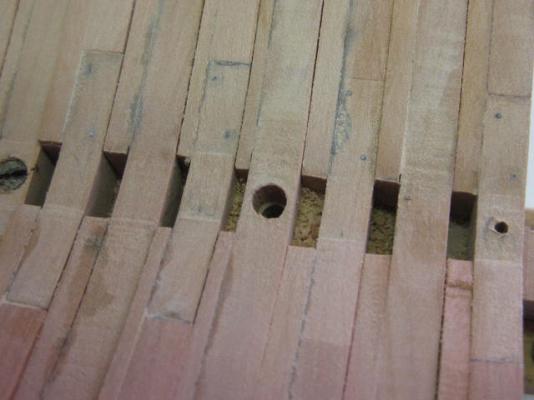
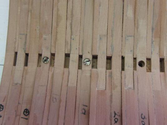
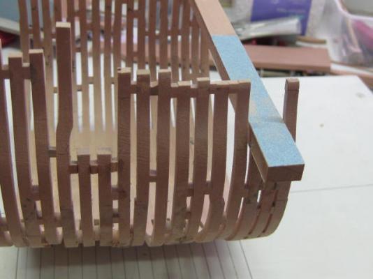
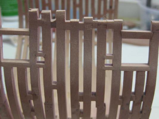
Belated thanks for the Xmas wishes Tom - I've been away visiting my family over the holiday and have just returned home now . It seems like an age since I last updated my log (it's been over a month, but a lot of work had been done since then). My apologies for the slackness . All the frames have been cut and assembled : The frames have all been glued to the keel, and the Filler Pieces have been also fitted. Fairing the inside is shown here - first by using a drum sander on the Dremel to take off any large high areas. The rest was faired using a rounded cork sanding block : As I hadn't used the mounting screws to hold the Rising Wood and the Keel together, they started to separate as I started gluing frames on, so I screwed the two pieces together through some of the frames for extra strength. The screws will be covered by the Keelson : Next, the Ports were trimmed out and a long sanding stick was used to level the tops of the frames in readiness for the lower sills : The port sills and Sweep Port sills after fitting : And after Fairing : The hull was then removed from the building board and placed on a piece of foam for the final external fairing : Danny


- 268 replies
-
- 31
-