MORE HANDBOOKS ARE ON THEIR WAY! We will let you know when they get here.
×

.jpg.6c90d67e7e9071af590f4d4a2a8bc908.jpg)
Waldemar
-
Posts
938 -
Joined
Content Type
Profiles
Forums
Gallery
Events
Everything posted by Waldemar
-
.thumb.jpg.c6343966b029e7941df5b987d129aac6.jpg)
Mathew Baker's early concept of ship hull design, ca. 1570
Waldemar replied to Waldemar's topic in Nautical/Naval History
True. It is usually a mix of both, more or less. Now I should perhaps make an update of all drawings, at least where the keel length and its derivates are given, but that is much work and dimensional differences rather small, quite within working tolerances. Either way, I am satisfied that the conceptual idea of Baker's ship has been hopefully found and its components identified on his plan. -
Mathew Baker's early concept of ship hull design, ca. 1570
Waldemar replied to Waldemar's topic in Nautical/Naval History
Bingo! A small update. moulded breadth: 24.3 feet 24.3 x 2.5 = 60.75 feet The calculated value of 60.75 feet may be the true length of the keel, which is quite elusive to measure very accurately on the drawing. -
Mathew Baker's early concept of ship hull design, ca. 1570
Waldemar replied to Waldemar's topic in Nautical/Naval History
Thank you very much Druxey! You have drawn my attention to the fact that, unlike many other examples, here the moulded breadth (taken as the width of the master frame design grid) equals the breadth at the main deck level. And Baker is known to have experimented with different proportions or configurations, so perhaps that was his intention in this case. Either way, here are the desired dimensions: keel length: 60.7 (~60) feet breadth at the 1st deck: 21.567 feet breadth at the 2nd (main) deck: 24 feet The only round ratio I have been able to spot is that of the breadth at the 2nd deck to the keel length (and even this only after rounding the keel length to 60 feet), which is 1 : 2.5. -
Mathew Baker's early concept of ship hull design, ca. 1570
Waldemar replied to Waldemar's topic in Nautical/Naval History
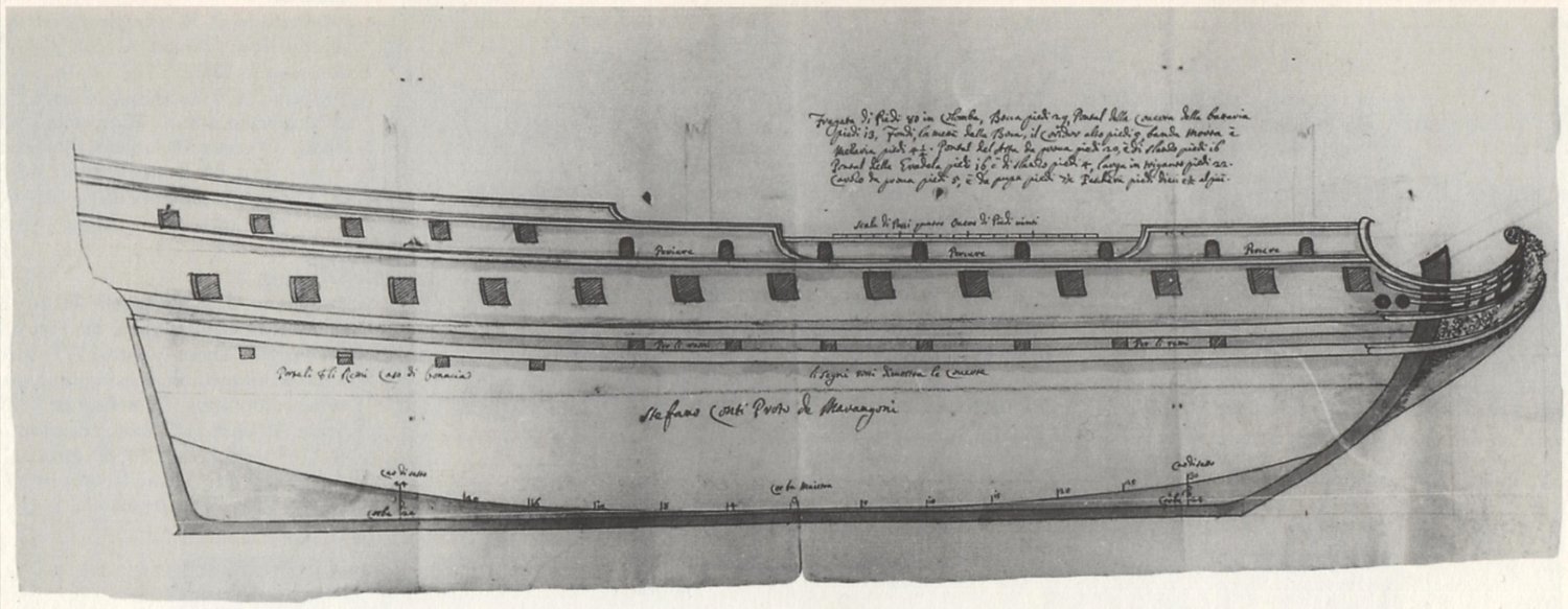
And to conclude this thread, below is a reproduction of a ship plan drawn by Venetian shipwright Stefano Conti (original in the Archivio di Stato, Venice), to be built according to the Mediterranean method. Just one comment here: in its place of origin, the Mediterranean method of frame moulding (i.e. non-graphical!) was apparently still in use even for large ships as late as around 1700.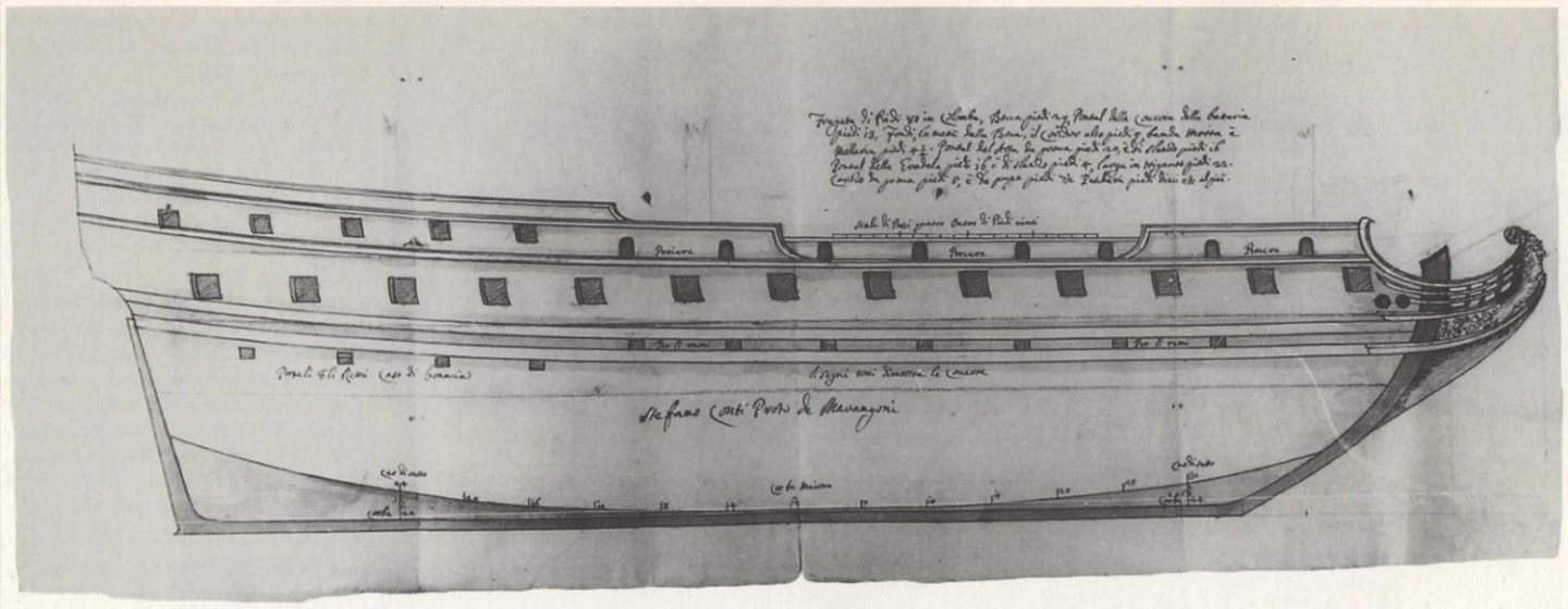
-
Mathew Baker's early concept of ship hull design, ca. 1570
Waldemar replied to Waldemar's topic in Nautical/Naval History
It is possible that one more element of the utmost conceptual importance can be better explained (I am trying to understand this drawing as I go along), and that is the exact location of the geometric device used to limit the rotation of the futtock template. This is shown on Baker's draught as a short horizontal line, which I interpret as being placed on the level of the first, undrawn deck. The measured distance between this first deck and the (drawn) main deck above is 5.5 feet. And perhaps more importantly, the height of the first deck above the base line is exactly 8 feet. It would be another hallmark of the Mediterranean methods, which were originally developed for the single-decked vessels like galleys and other low board craft. In this very case, however, it is a rather confusing application, as the narrowing line of the greatest breath (visible on the plan view) is roughly on the level of the main deck, and not on the level of the first deck. No wonder it was soon replaced in graphical methods by a more lucid means, and at the same time more adapted for larger vessels. This is illustrated in the graphic below.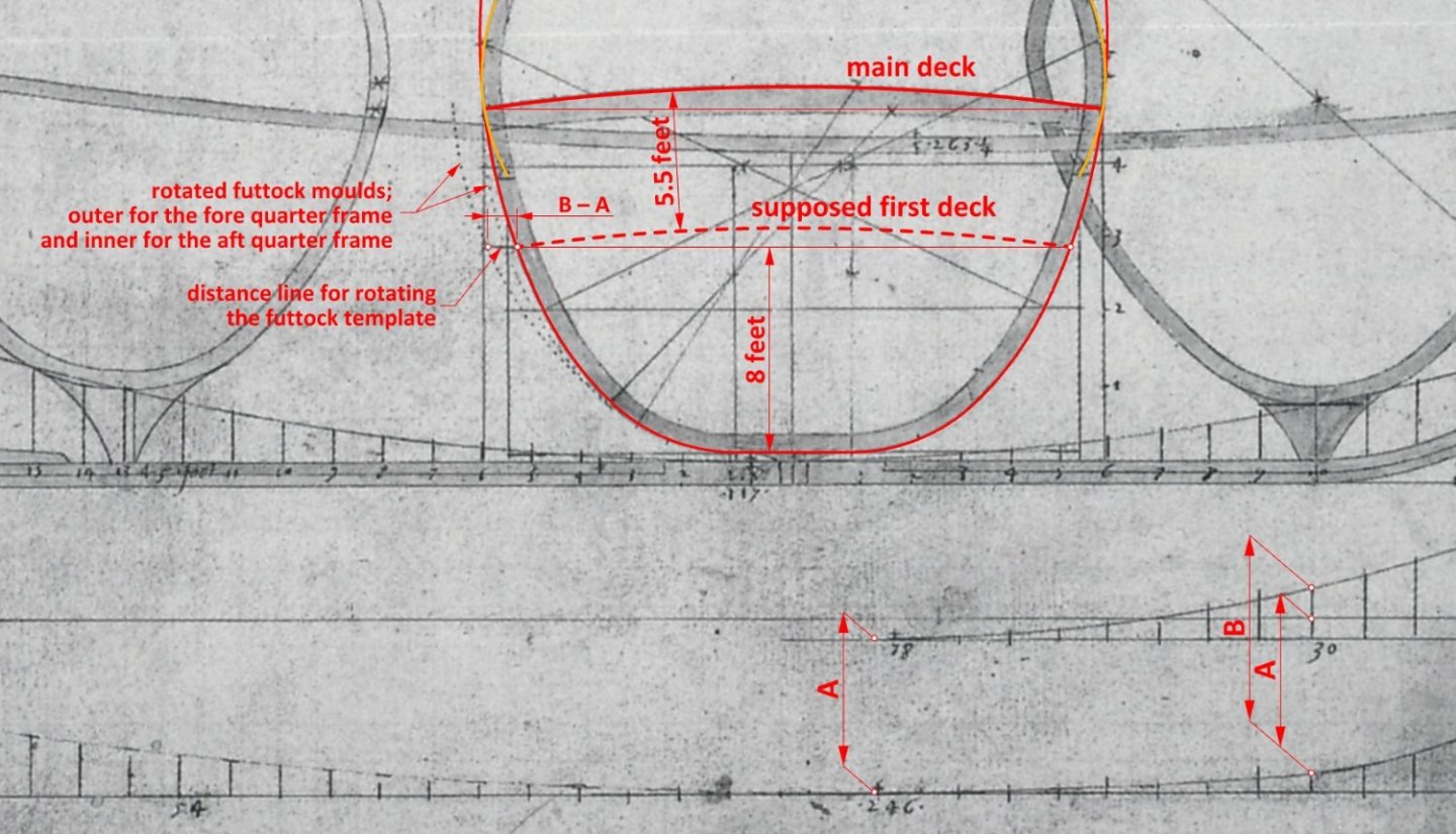
-
Mary Rose – an English ship of the Mediterranean concept
Waldemar replied to Waldemar's topic in Nautical/Naval History
A graphic example below of a master frame from the mid-16th century Italian manuscript Arte de far Vasselli by Todaro de Nicolò (http://echo.mpiwg-berlin.mpg.de/MPIWG:7KTSNYA6). The scale for sliding (rotating) the futtock template is clearly visible on the bilge arc.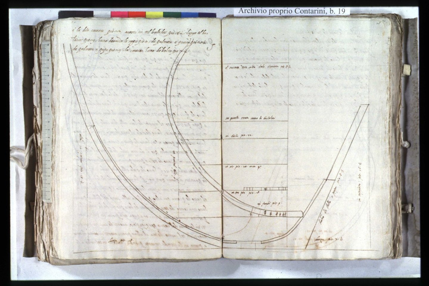
-
Jaager, that's great. Why don't you try to clear it all up for the people who do this professionally? Or have you already done so? What was their reaction?
-
Jaager, you have already truncated my statements twice in such a way that their meaning has been altered, and your comments refer to these truncated statements. Please reread my statement in post #12 and you will realise that your comments actually bear little relation to the original meaning.
-
Interesting. Could you give at least one such example based on contemporary evidence?
-
Jaager, are you aware that Ab Hoving was reconstructing the shape of hulls precisely by building scale models? By making such a statements, you have just annihilated much of the efforts made so far by Ab Hoving, as well as by many scientists and archaeologists who reconstruct the shape of ships precisely by building models. At different scales, e.g. 1:5, 1:10 and so on. Or is it perhaps an unintentional contradiction?
-
Moderators? Anyone can make a blunder sometimes, but after all, this is already an obvious personal attack rather than a seemingly stated desire for a substantive discussion....
-
Specifically for this issue I have also consulted early English texts on shipbuilding as well as ship plans. Somewhat promisingly, I found that some of them suggest the use of round sterns as early as about 1600. But this is a subject for a rather long commentary requiring proper preparation...
-
Okay, maybe it's easier to bid with my head because I have a spare... 🙂

-
I will give my head that these drawings of ships were created for exactly the same reasons that we build models of them today – for their beauty, for sales, for display, for satisfaction.... 🙂
-
So fast!? And professional work at the level of museum models. It makes you want to help...
-
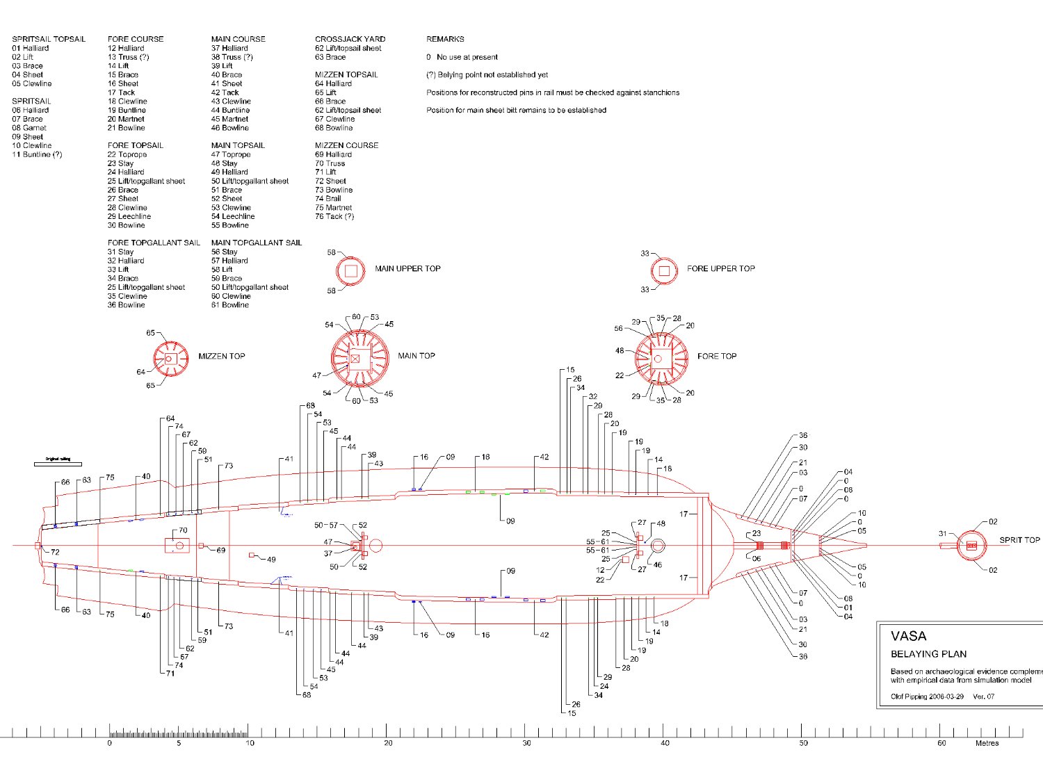
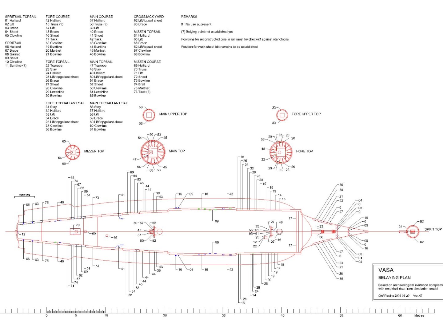
A newer version of the belaying plan was posted on the Vasa forum some time ago by Fred Hocker. Not of the highest resolution, but still quite readable. Here you are.
-
There is probably direct evidence that Sovereign of the Seas had a round stern from the outset. In McKay's book, on pages 20–21, there is a table of the ship's projected dimensions from 1635 ('Detailed Schedule of Dimensions for the proposed Sovereign of the Seas'). In this table I found, among other things, these two dimensions: Height of the tuck at the fashion piece: 16' 0" Height of the tuck: 17' 0" 'Height of the tuck' is nothing more than the height of the rising line of the floor aft (i.e. at the sternpost). In short, for ships with a square stern the first given dimension is not necessary at all, and even meaningless (at least I personally do not know of such a case). It would now be sufficient to check the reliability of these figures given in McKay's book (incidentally largely ignored by the author himself in making his drawings) and whether they all refer to the ship as first build or to her later rebuilds. I think Mark would be best placed to do this. I would also add that it would be difficult to dream up more complete data for reconstructing the hull shape of a ship of this era. No or almost no guessing, just the implementation of ready-made data...
-
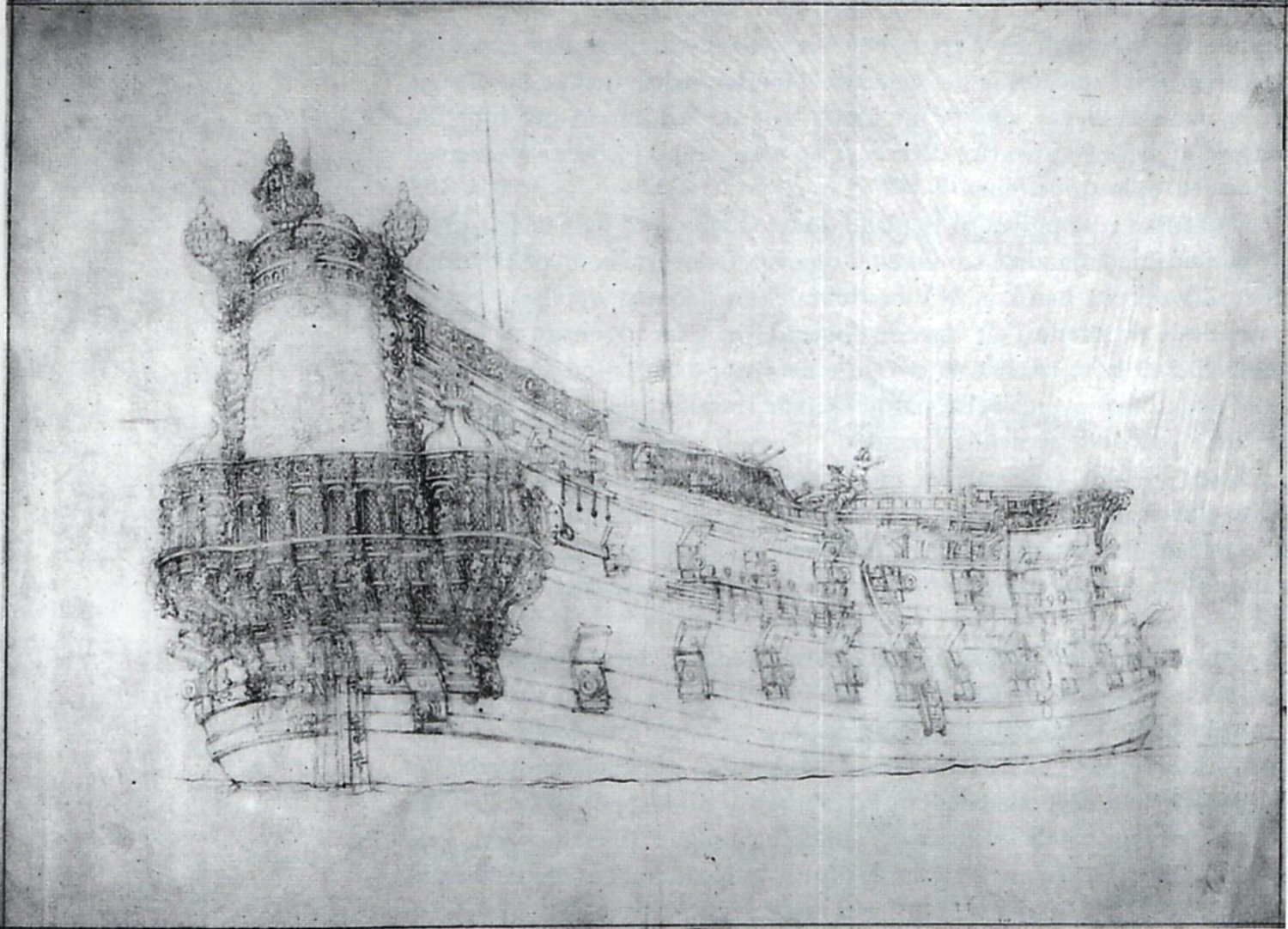
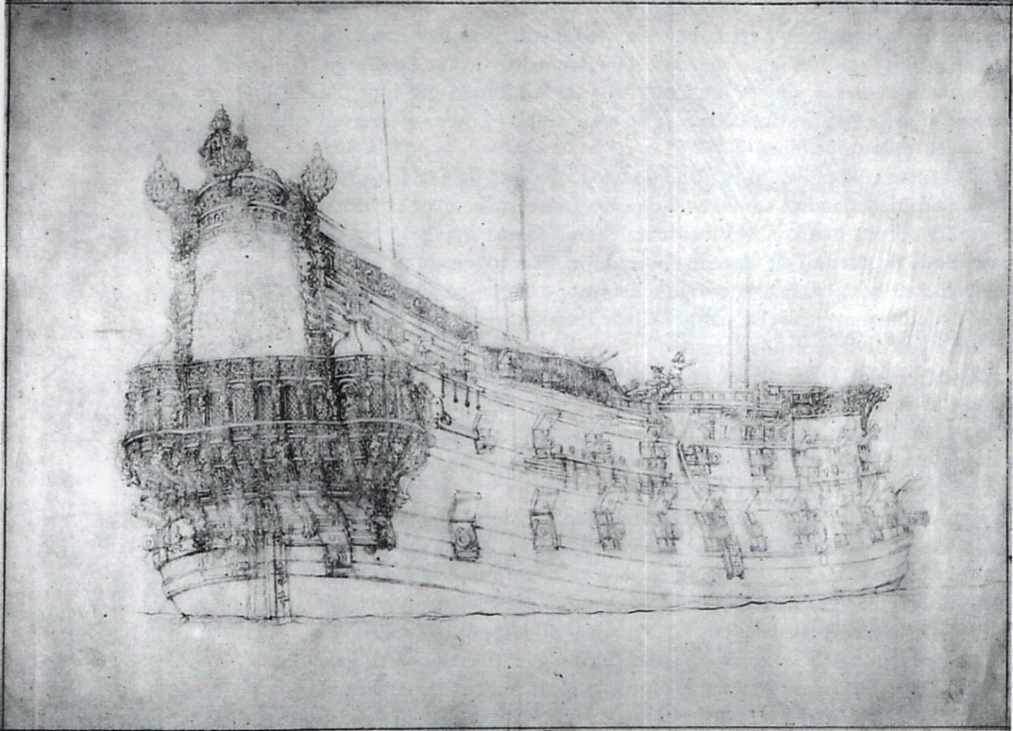
To illustrate another unorthodox case, below is a somewhat surprising example of a ship's stern from a presumed transitional period. The portrait was made by van de Velde in 1658 and depicts the famous Danish admiral ship Trefoldighed (the equivalent of Nelson's Victory for the Danes). The ship was rebuilt by English shipwright James Robbins in the 1640s at the behest of Christian IV and was then given a round stern. Note the run of the lowest wale and the position of the stern gun ports. The transitional sterns of some French ships in the second half of the 17th century had a similar layout. The picture was taken from the study by Niels Probst, Christian 4.s flåde, 1996.
-
This is, of course, an absolute condition for our assistance
-
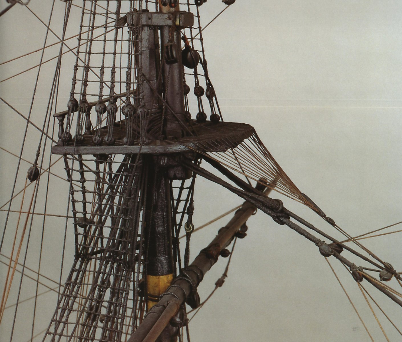
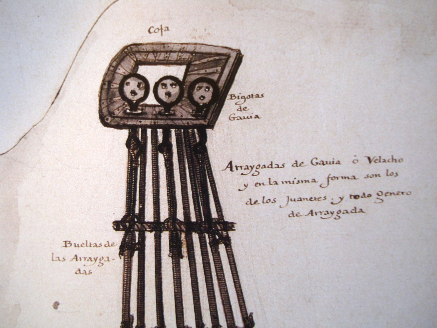
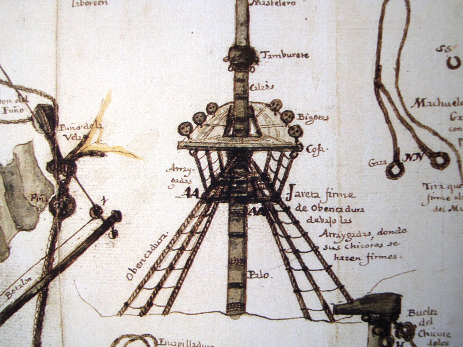
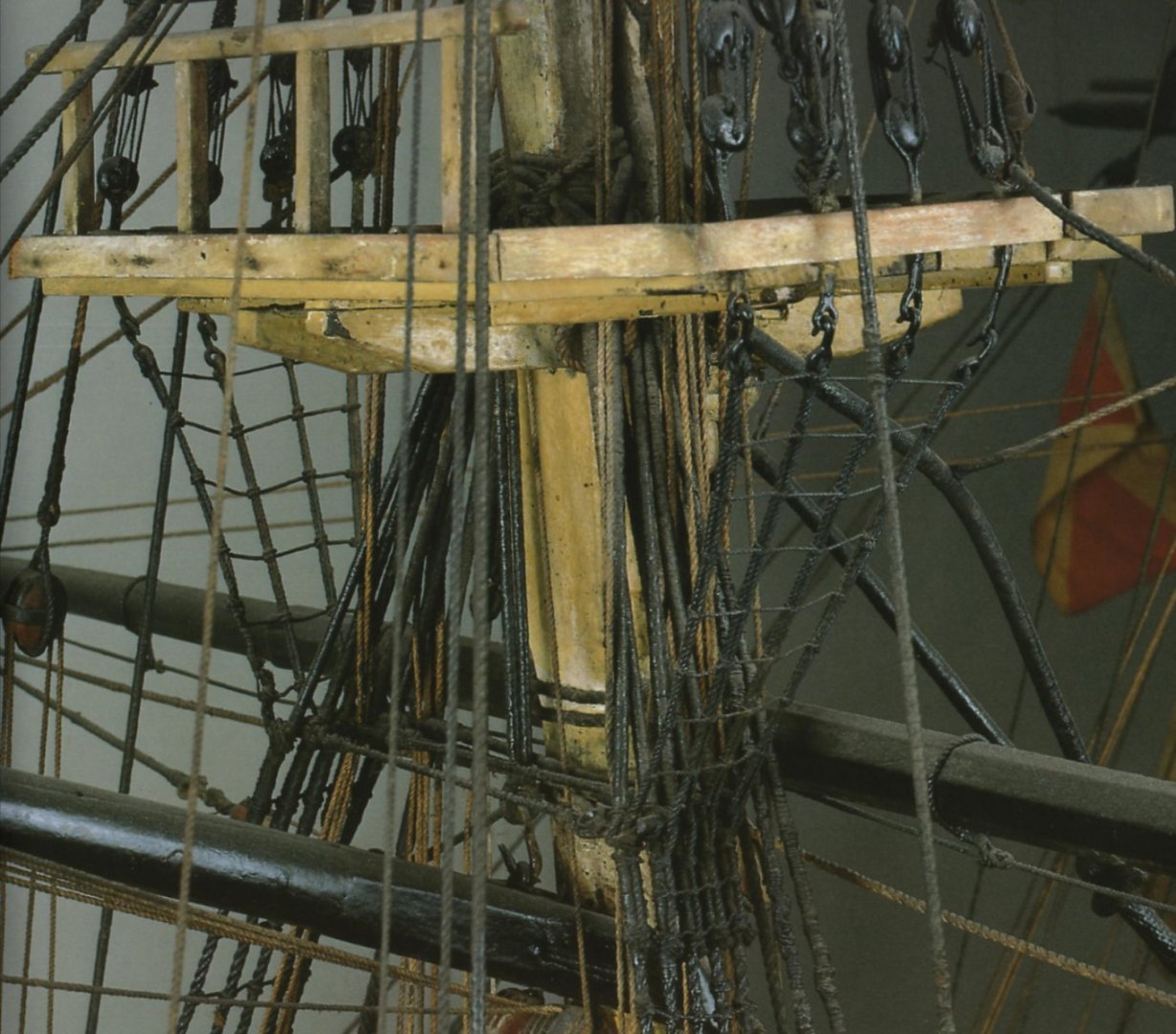
Photographs of Spanish ship models featuring original rigging from a slightly later period. While possibly different when it comes to the detailed configuration of catharpins, yet perhaps they will help to better interpret the above drawings from the Álbum (serving, worming, colours). In compressed files, the same photographs in higher resolution (both from the Modelos de Arsenal del Museo Naval, 2004). Santa Ana 1784-1816: Santísima Trinidad 1769-1805: Santa Ana 1784-1816.zip Santisima Trinidad 1769-1805.zip

-
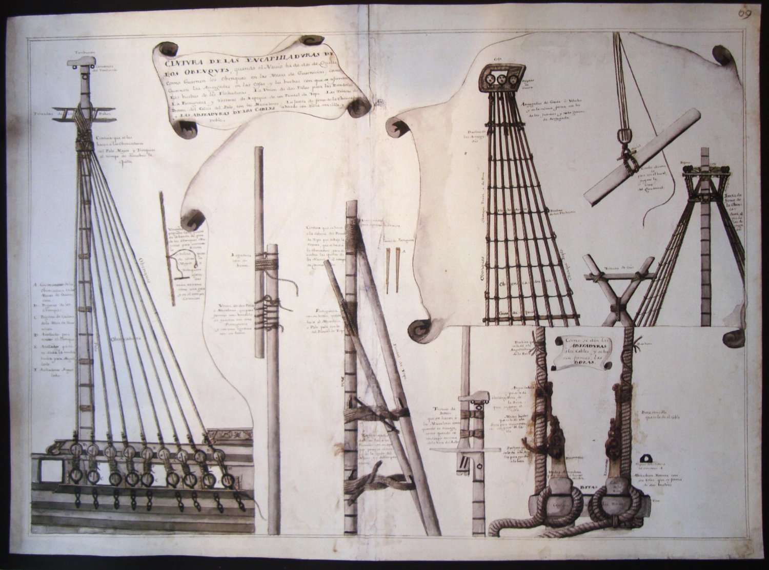
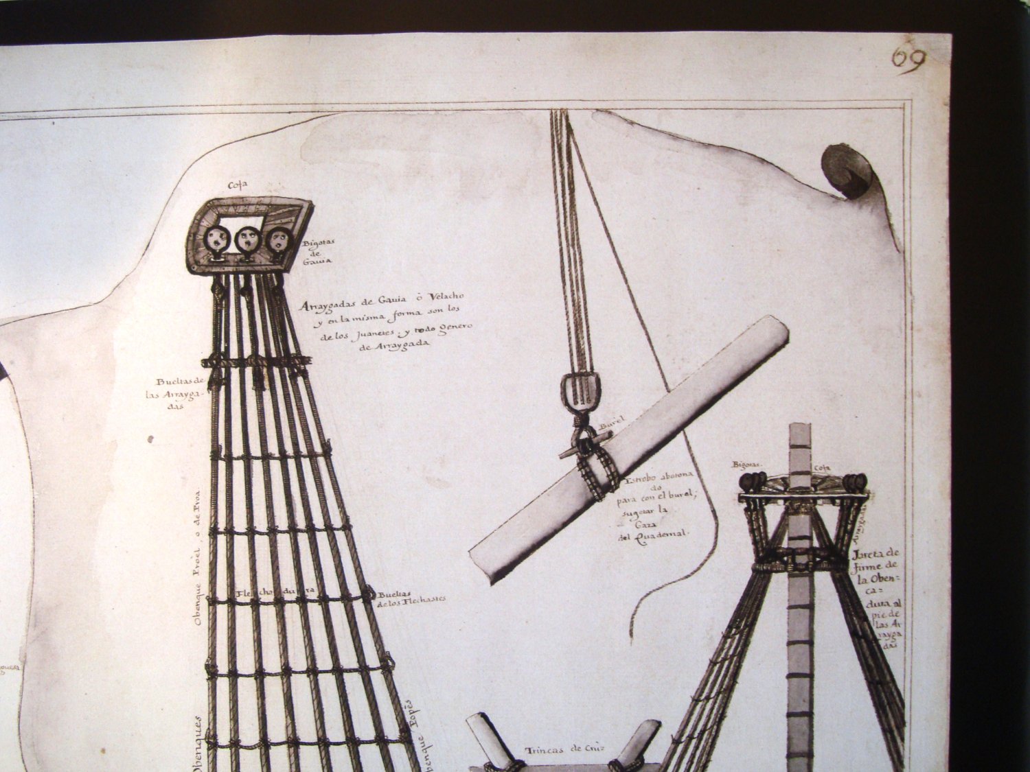
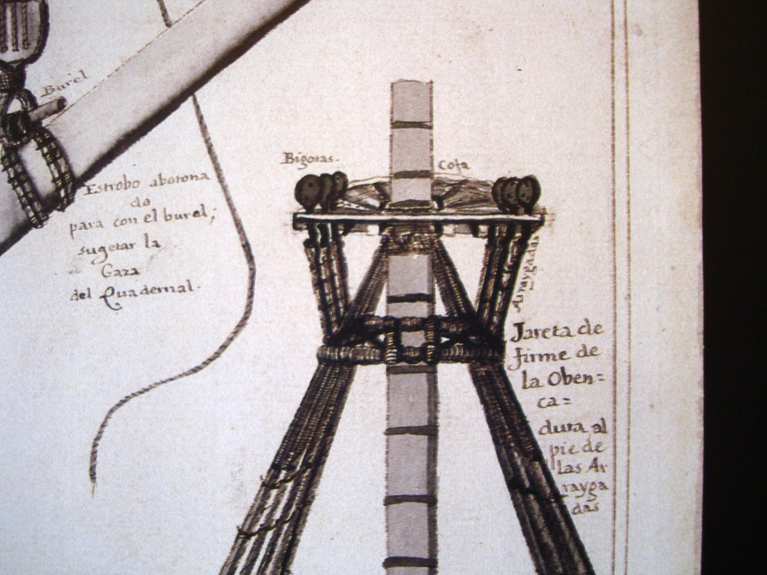
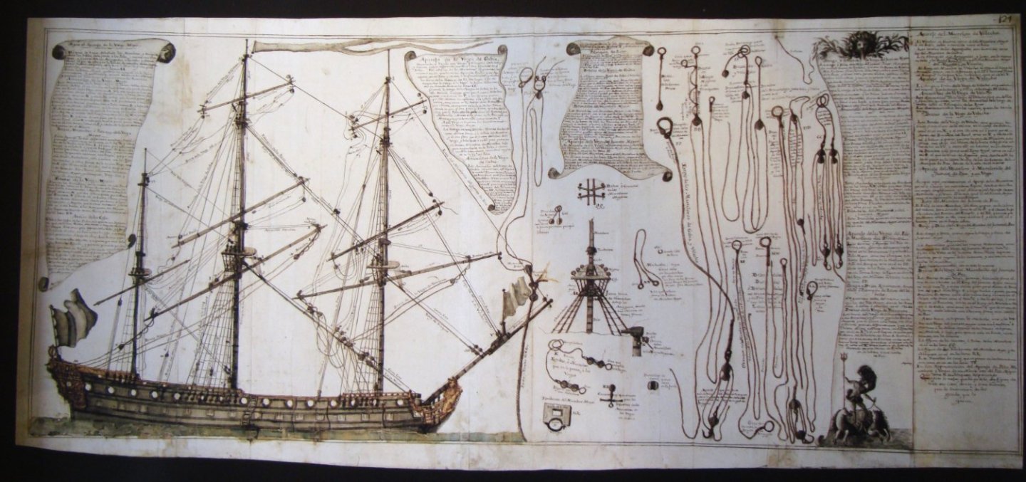
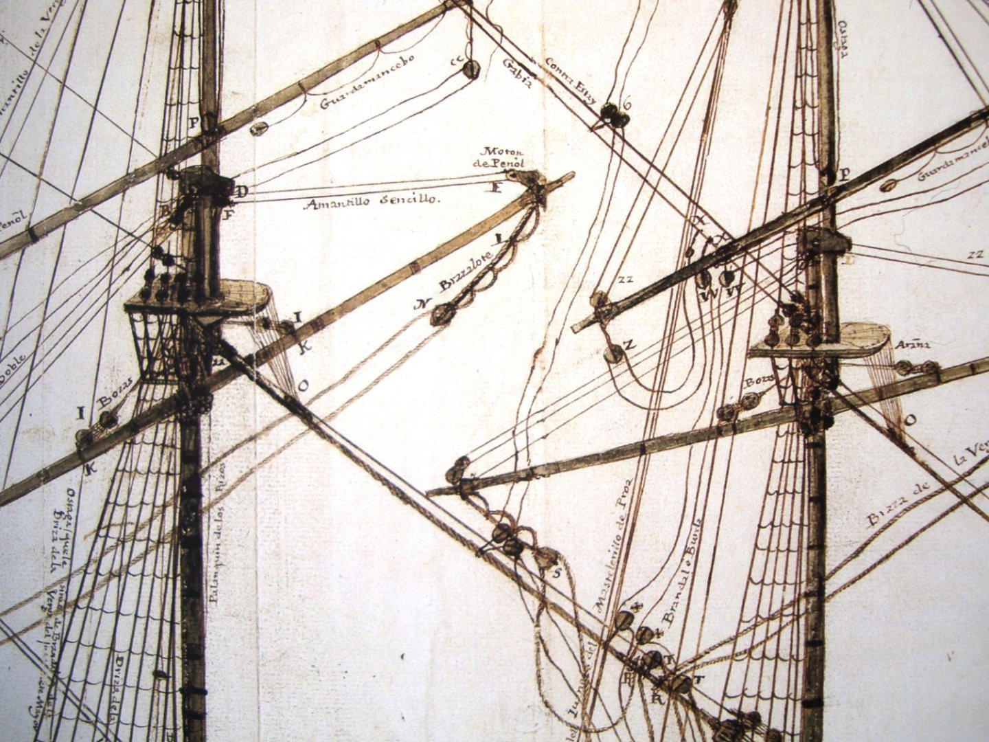
Plate 69: Plate 124:


-
I have checked my copy of the Spanish Álbum del Marqués de la Victoria (created 1719–1756). Everything is there, even the priest's utensils and the officers' tableware. The only relevant thing I found there are the fixed catharpins connecting the futtock shrouds staves. Shown in a rather indistinctly way, as thick ropes.
-
If my two cents are taken into account: – I agree with the Druxey's view in post #2, that it is about the transitional form of the stern. Specifically, that the stern is round, but with the still sharp edges of the stern closer to the ship's sides; – at least some of the planks (in the more difficult spots) were cut from compass timber, such as those shown by Steven in post #13 and described by Mark in post #12; – also consider that the height of the tuck was a compromise between rudder effectiveness and adequate stern support; for the square tucked ships this height was virtually never above the waterline, but always below. In other words, the bottom part of the stern surface was always under water. In any case, ships were then rather more sail-controlled than just rudder-controlled; – Even a cursory look at the way the station lines were drawn (p. 157 in McKay's book) is not optimistic. In soldierly terms: for me it is a rather strange improvisation which cannot be quite trusted. As an aside: I find the drawings of the gun carriages particularly painful, especially because of the faulty positioning of the transoms (they should be under the trunnions rather than completely in front of the carriages).
-
TRADUCTION MESSAGES
Waldemar replied to LEFEBVRE's topic in Using the MSW forum - **NO MODELING CONTENT IN THIS SUB-FORUM**
Essayez aussi https://www.deepl.com/ Excellentes traductions contextuelles. La terminologie spécialisée devra bien sûr être corrigée manuellement. Also try https://www.deepl.com/ Excellent contextual translations. Specialised terminology will of course have to be manually corrected. -
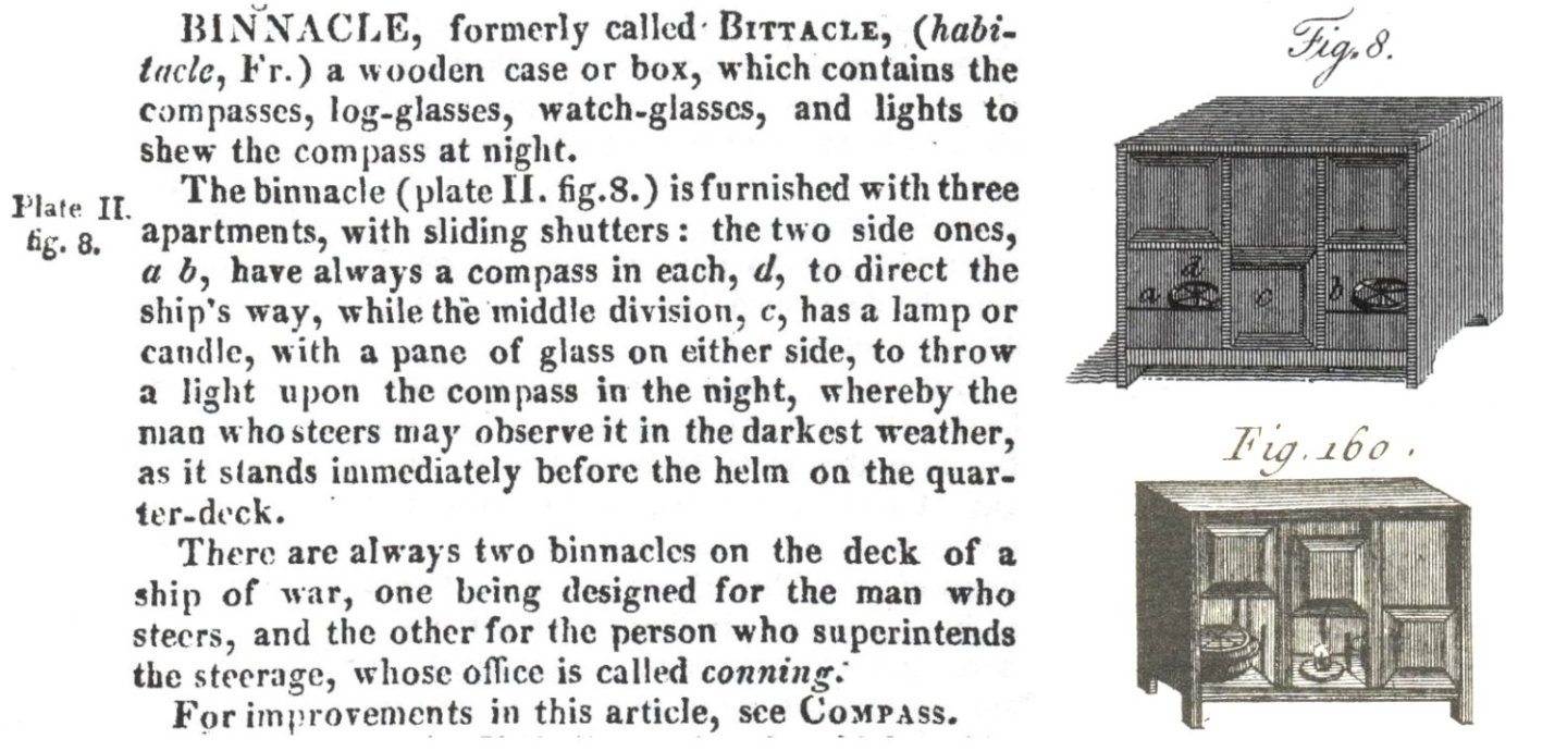
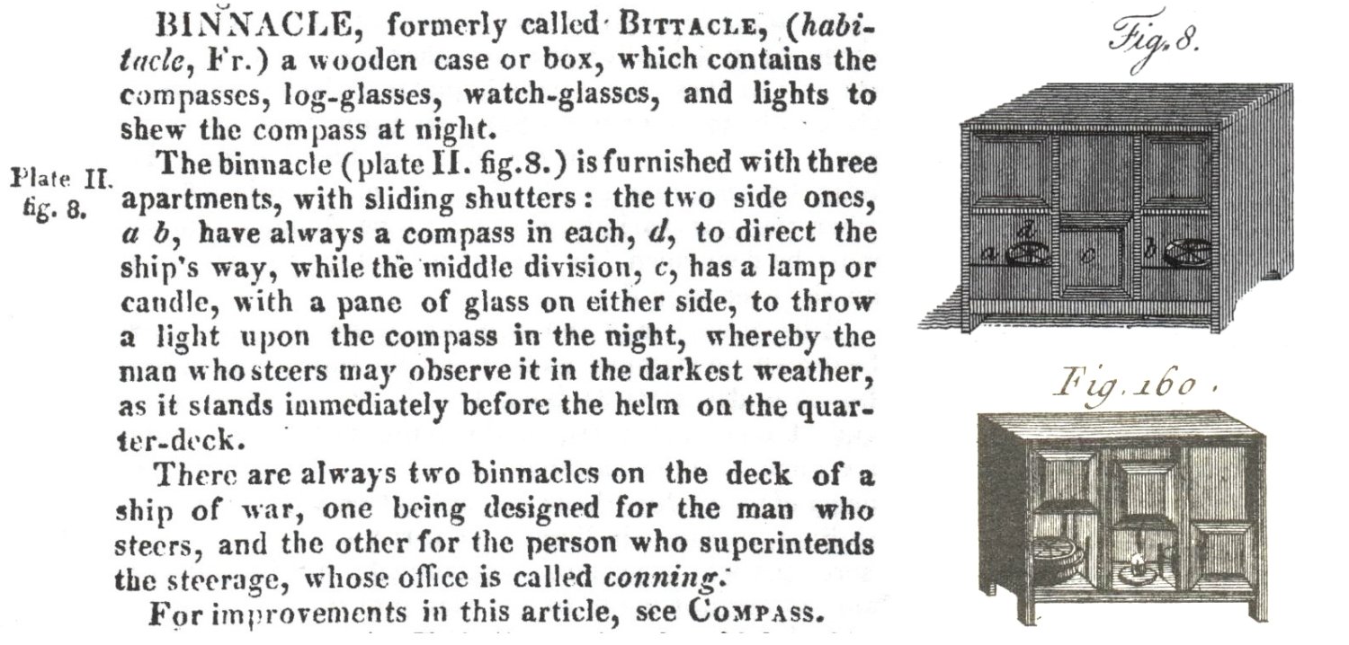
Superb workmanship indeed. For those interested I just want to show the definition of binnacle taken from the Falconer's New Universal Dictionary of the Marine, 1815 edition. As far as the construction of binnacle is concerned, the definition in the French Encyclopédie Méthodique. Marine, 1783, is virtually the same, so just the drawing from that work (below). Maybe others will add something else, such as relevant photos of period models.