BETAQDAVE
-
Posts
5,386 -
Joined
-
Last visited
Content Type
Profiles
Forums
Gallery
Events
Everything posted by BETAQDAVE
-

drilling hole through wire
BETAQDAVE replied to BETAQDAVE's topic in Metal Work, Soldering and Metal Fittings
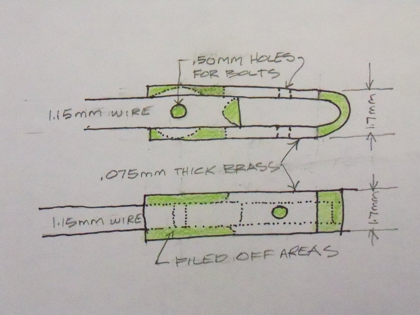
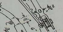
Well, I gave up trying to salvage that first attempt to make the davit since trying to anneal the 1.15mm wire at this point would only melt the solder that was already holding the flats on the end. So, after receiving my new functioning torch, I came up with a different method that would work with my limited tools and skill working with metal. This is a rough sketch of my idea of how remake the end of the davit. It solved the multiple problems of drilling that hole, fattening the sides of the wire, and adding the flats on the end at the same time. After annealing some 1.15mm wire and 1.7mm wide 0.075mm thick strip of brass, the wire was bent into shape and the brass strip was folded in half over some 1.15mm wire. The next step was to clamp and solder the strip to the end of the wire as shown being sure to use enough solder to fill the gaps on the top and bottom between them. A scrap of 1.15mm maple was slipped into the gap between the sheet for support and maintain the alignment between them and a 0.50mm hole was drilled through for an eye bolt. Then the folded over end portion on the right of the strip shown in green was cut off and filed into its finish shape. While the newly fattened portion of the wire on the left was clamped in my vice, the top and bottom areas of the strip and solder in green were filed off flat to the surface of the wire. Now that there was a wider surface to work with, it was clamped in the vice, a heavy needle was used as a center punch, and that pesky 0.50mm hole that created such a problem before was finally drilled for the other eye bolt. The final step was to just file away the remaining brass sides shown in green into their rounded shape. Making a pair of eye-bolts from some 0.50mm brass wire, which were cut to the proper length to leave just enough exposed to glue a very short portion of some hollow thin wall brass pipe to serve as the nuts. Thanks to all of your suggestions guys. Apparently those drill bits I used actually were sharp, the annealing process really did make quite a difference! Here is a photo of the assembly as it stands now with its brace added.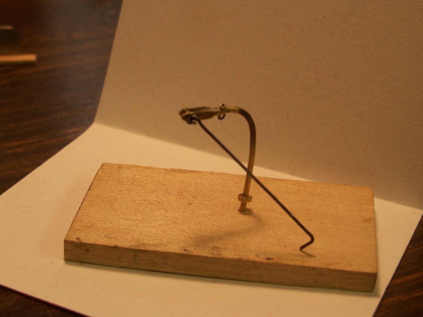
-
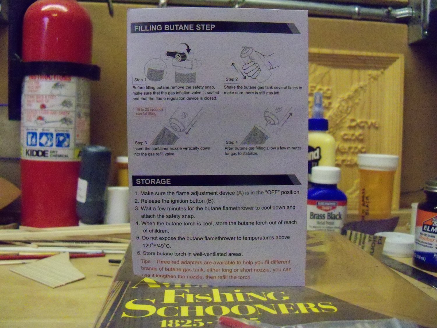
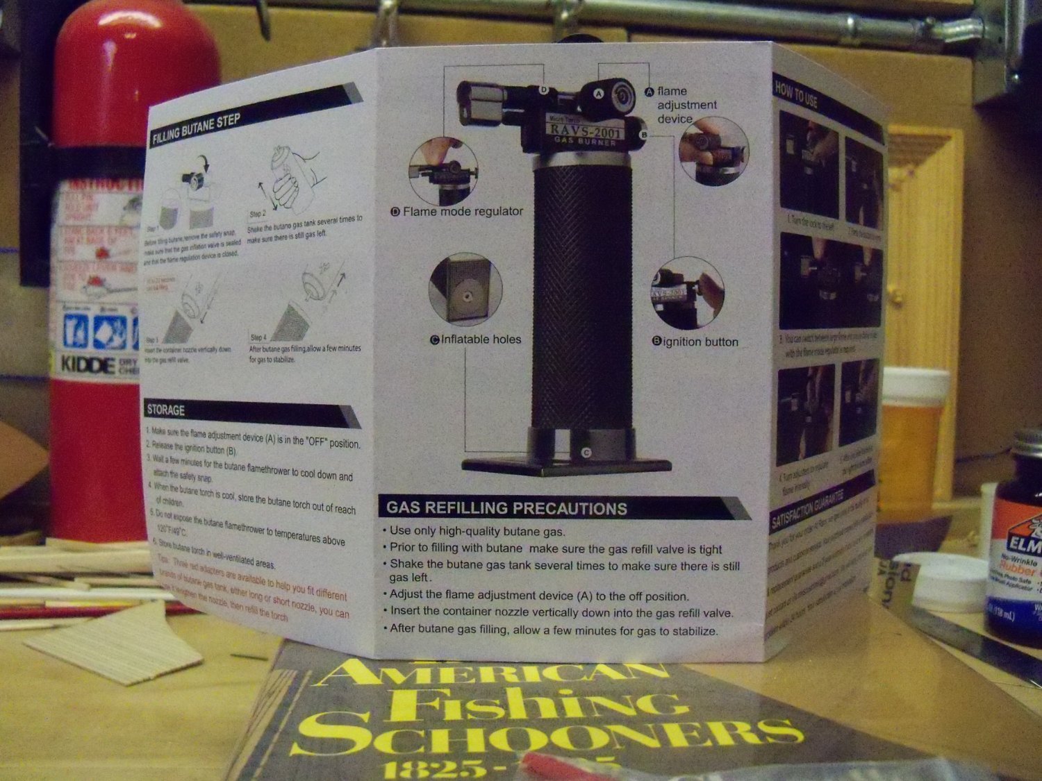
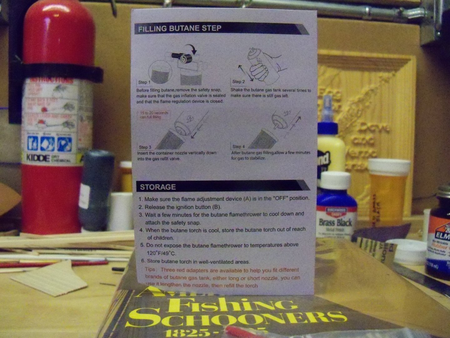
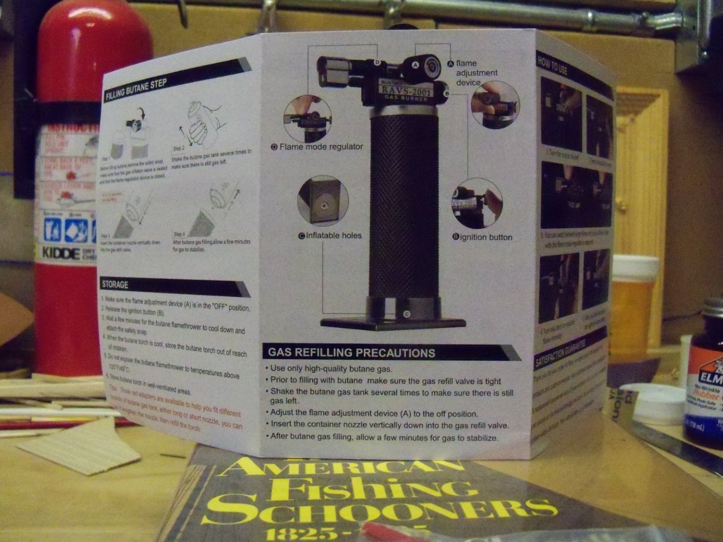
Well, my new torch arrived and I must say that I was pleasantly surprised. It was securely packaged and arrived just 4 days after I placed the order. In addition to the torch itself, there were some very well illustrated how-to instructions and a plastic bag with three plastic accessory fittings to aid in the filling and/or emptying of the butane gas. The instructions are written with the inexperienced user (like me) in mind, pointing out all of the features of the torch and how to use them. Having only used a soldering iron previously, I appreciated that even things that more experienced users wouldn’t even think twice about, were things that were explained here. This seems to be a very solidly built and rather stylish looking tool. It has a very stable chromed copper base, so concerns about tipping over are minimal. The metal gas tank has a built-in leak-proof inflation valve under the base that’s covered with a black diamond cut surface which makes it very easy for me to grip and stays cool to the touch. The business end has a long-angled and heat-resistant ceramic nozzle that helps to keep your hands safely away from the flame. It doesn’t come with butane gas (due to shipping restrictions), but it comes with those plastic fittings to allow filling from most commercially available butane gas bottles. Refilling the torch fully (8-11g) only took me about 10 seconds or so. The chrome plated copper piezo press ignition button made it easy for me to ignite a continuous flame and allowed me to use it one-handed. A flame mode regulator control, located just behind the nozzle, allows switching between 2 flame modes of either a tiny blue or a large yellow flame to control the heat. The manufacturer says that it can reach a maximum temperature up to 2,372oF (2372oC), but I’ll have to take their word for that as I have no way to measure that. There is also a fuel flow regulator dial on the side of the torch that allowed me to make additional flame adjustments. An additional safety feature is a cover that snaps over the fuel flow regulator dial which prevents the ignition button from being inadvertently depressed. It also came with a 2-year warranty. At this point I have experimented with it a little bit annealing some brass and soldering a few things and it does seem to be as good as advertised.


-
- 5
-

-
drilling hole through wire
BETAQDAVE replied to BETAQDAVE's topic in Metal Work, Soldering and Metal Fittings
Well, I did bite the bullet and ordered the RAVS-2001 torch from Amazon for about $23 with free shipping and it arrived just 4 days later. I will probably write up a review of it later, but since it actually works as advertised, I’ll be too busy in my shop making a new davit. 👍 -
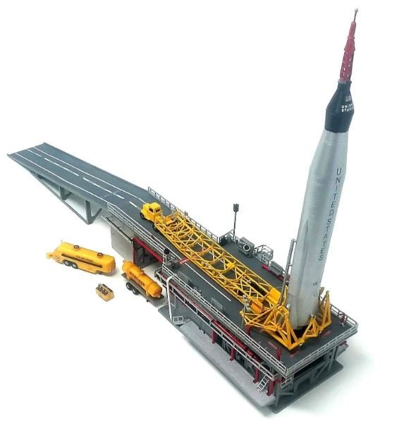
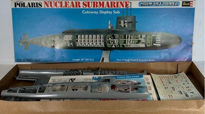
In my younger days, in addition to the few plastic models listed below in my past builds that I ended up selling, I also built numerous models of movie monsters, cars, military vehicles, rockets, and ships that met their demise through various means in the years since. There were a few of them that were the most memorable. One military vehicle that really stands out in my memory was the U.S. Army's M60 AVLB (Armored Vertical-Launched Bridge. It was an M60 Patton tank chassis with a hydraulic folding scissors bridge mounted in place of the turret. Developed in 1963, some of those are still in service around the world. Then there was the 1/123 scale Revell model of the Polaris submarine from back in the 60’s that had one side of it cut away to reveal its interior details, and the 1962 Atlantis 1/110 scale model of the Atlas rocket complete with its launch pad and the Mercury capsule shown here. One model that I sought, but was never able to get hold of was this 1/35 Tamiya model of the US M16 Halftrack pictured here. It was a M3 half-track fitted with a quad mounted 50-caliber Browning automatic heavy machine gun. My primary reason was that my father was a crew member of one of these going through France and Germany during WWII.

-
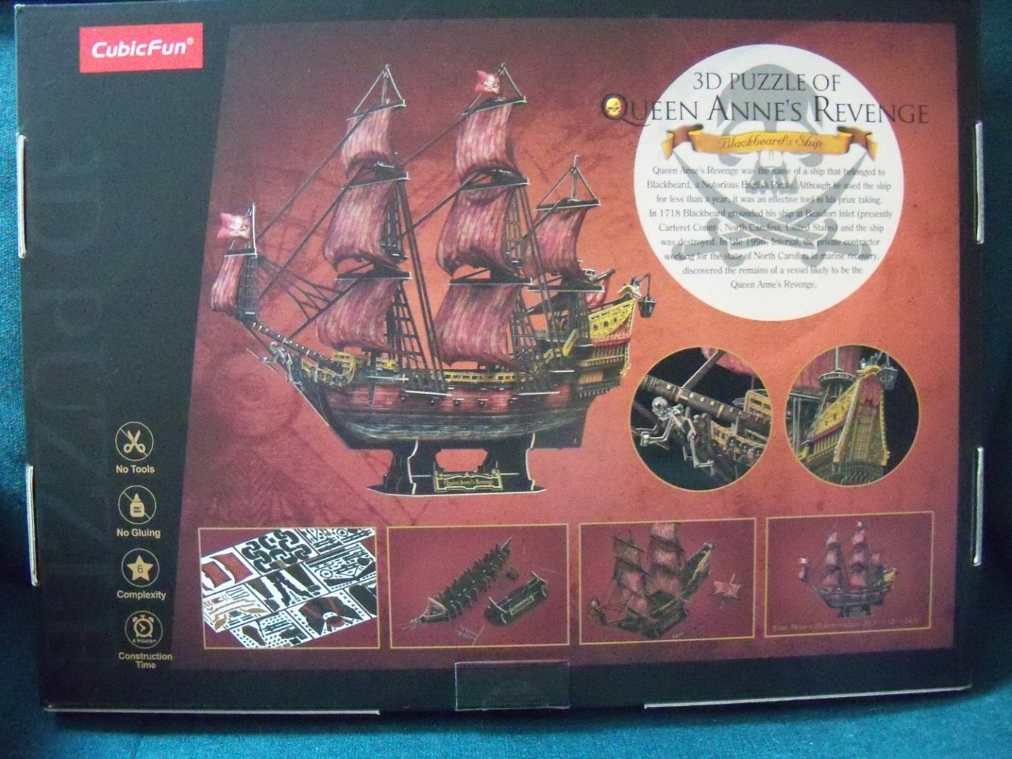
Opps, looks like this should have been put in its own kit review rather than added onto the American Revenue Cutter listing. Can anyone correct my error by putting it into its own review with the heading: Queen Anne’s Revenge (Blackbeard’s ship)? Sorry Jeff.
-
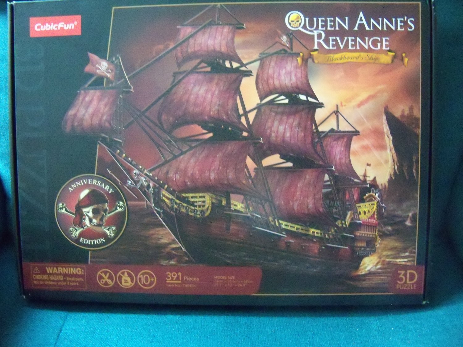
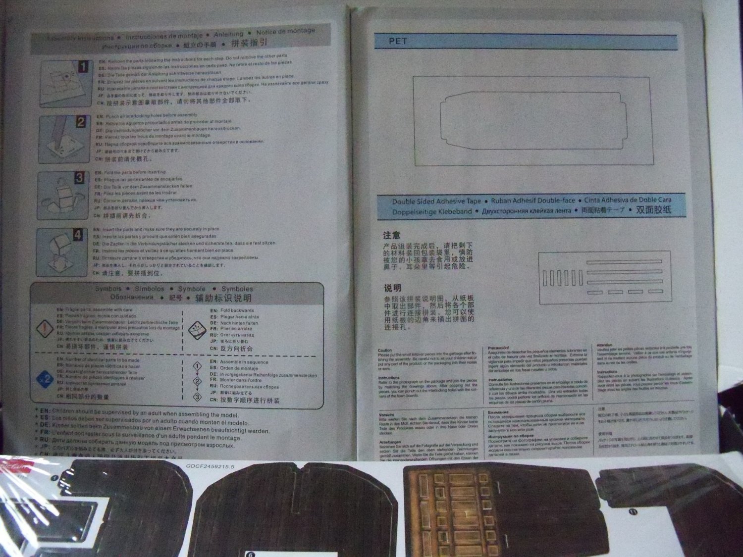
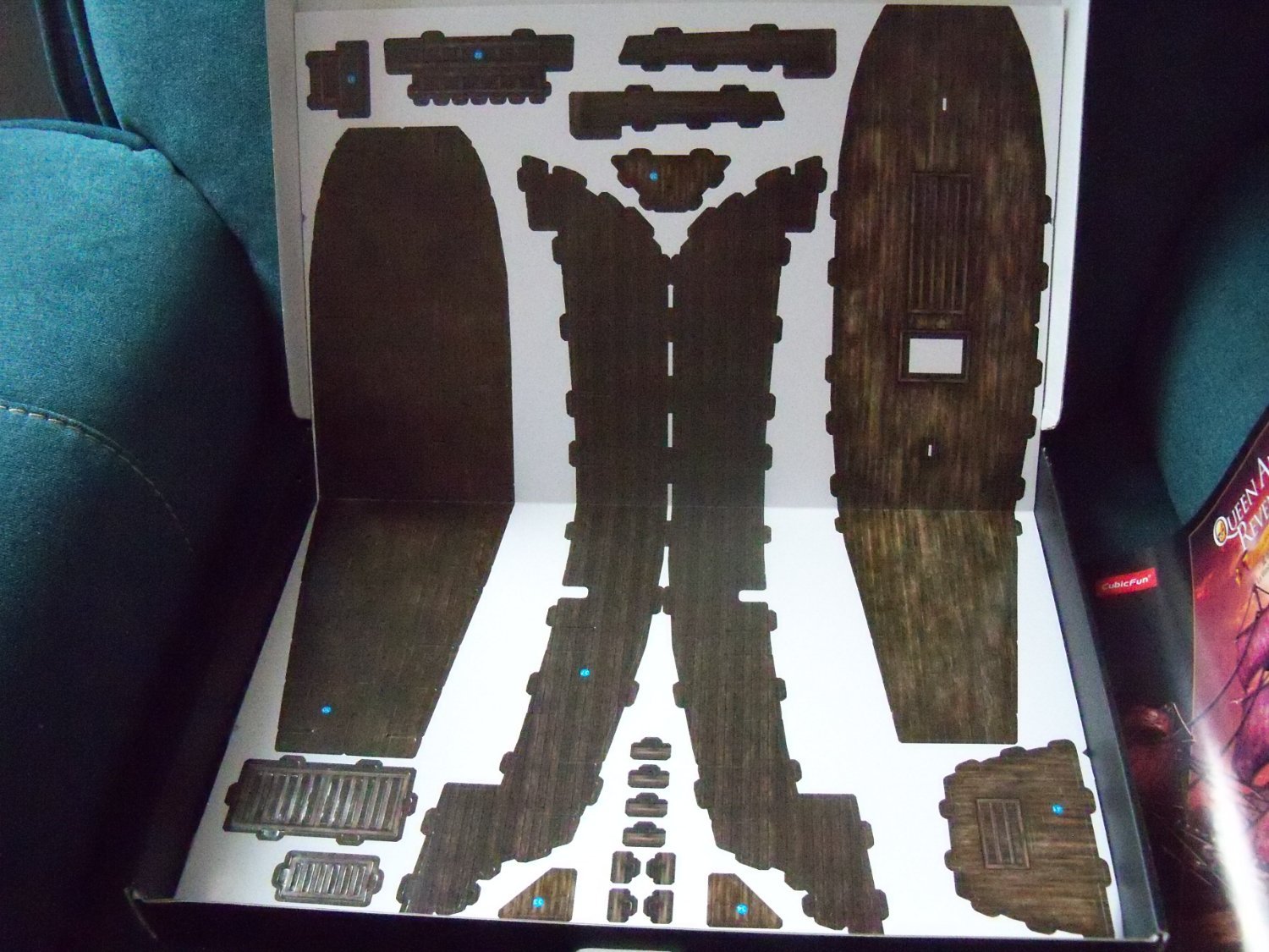
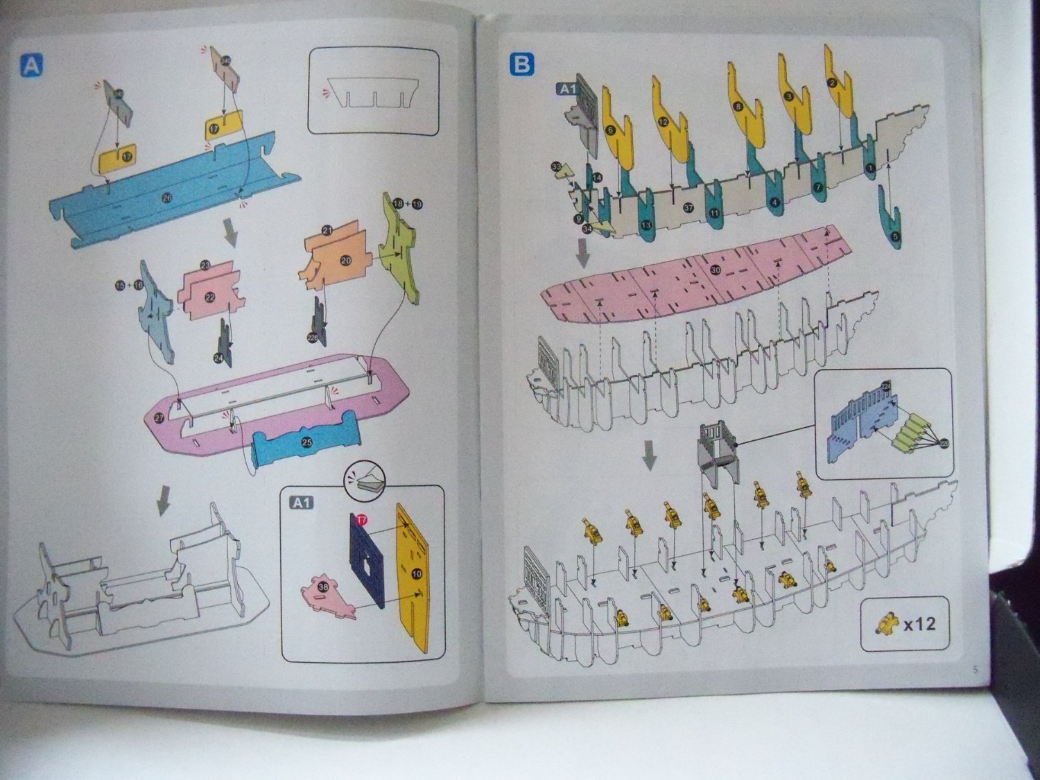
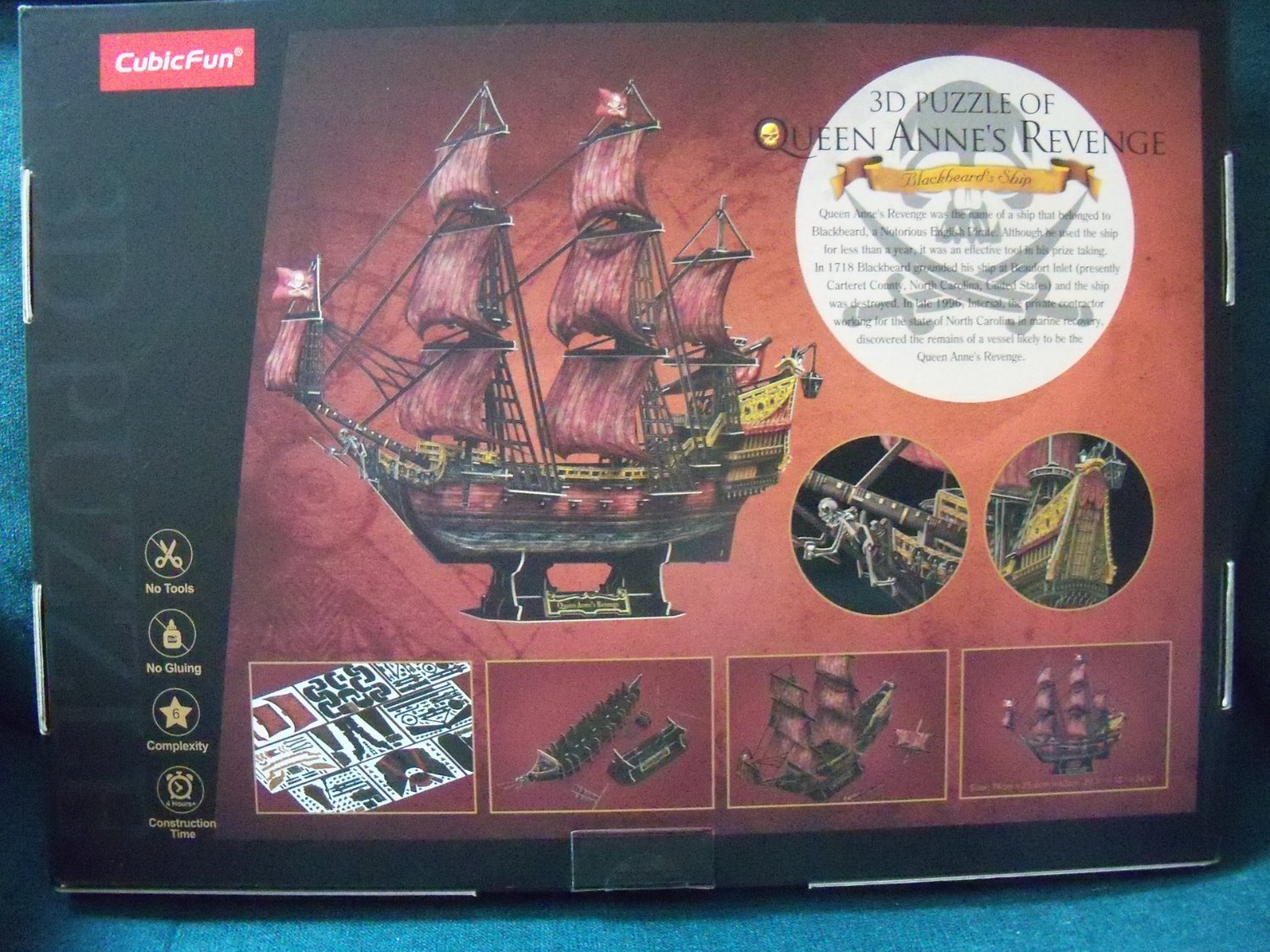
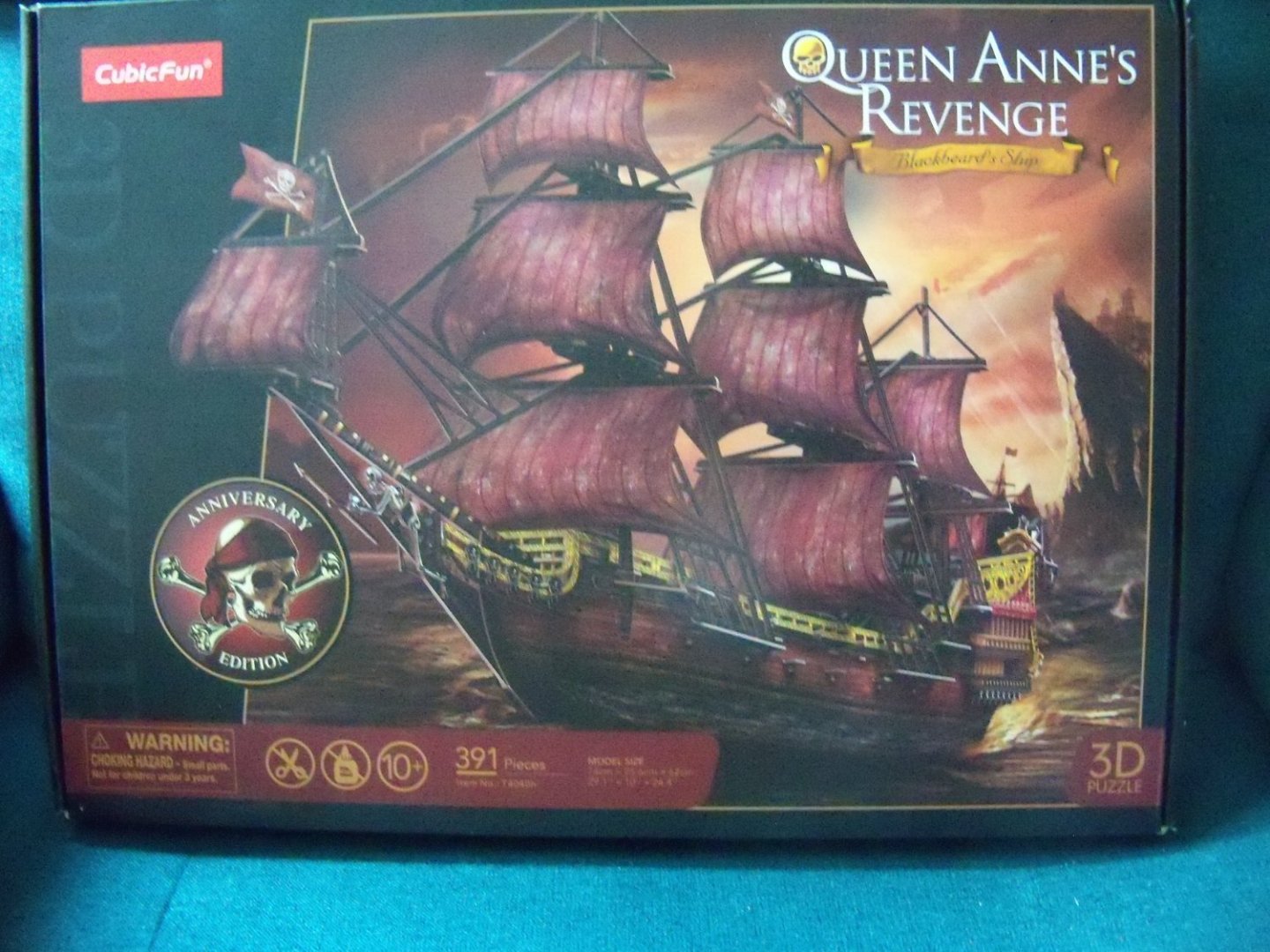
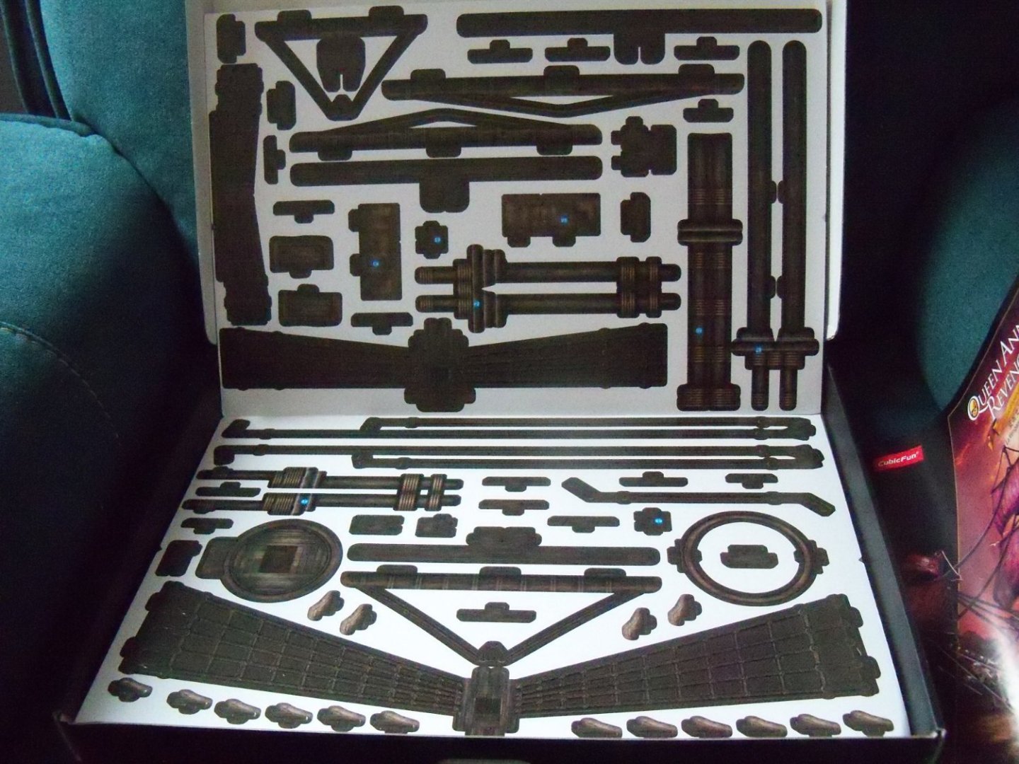
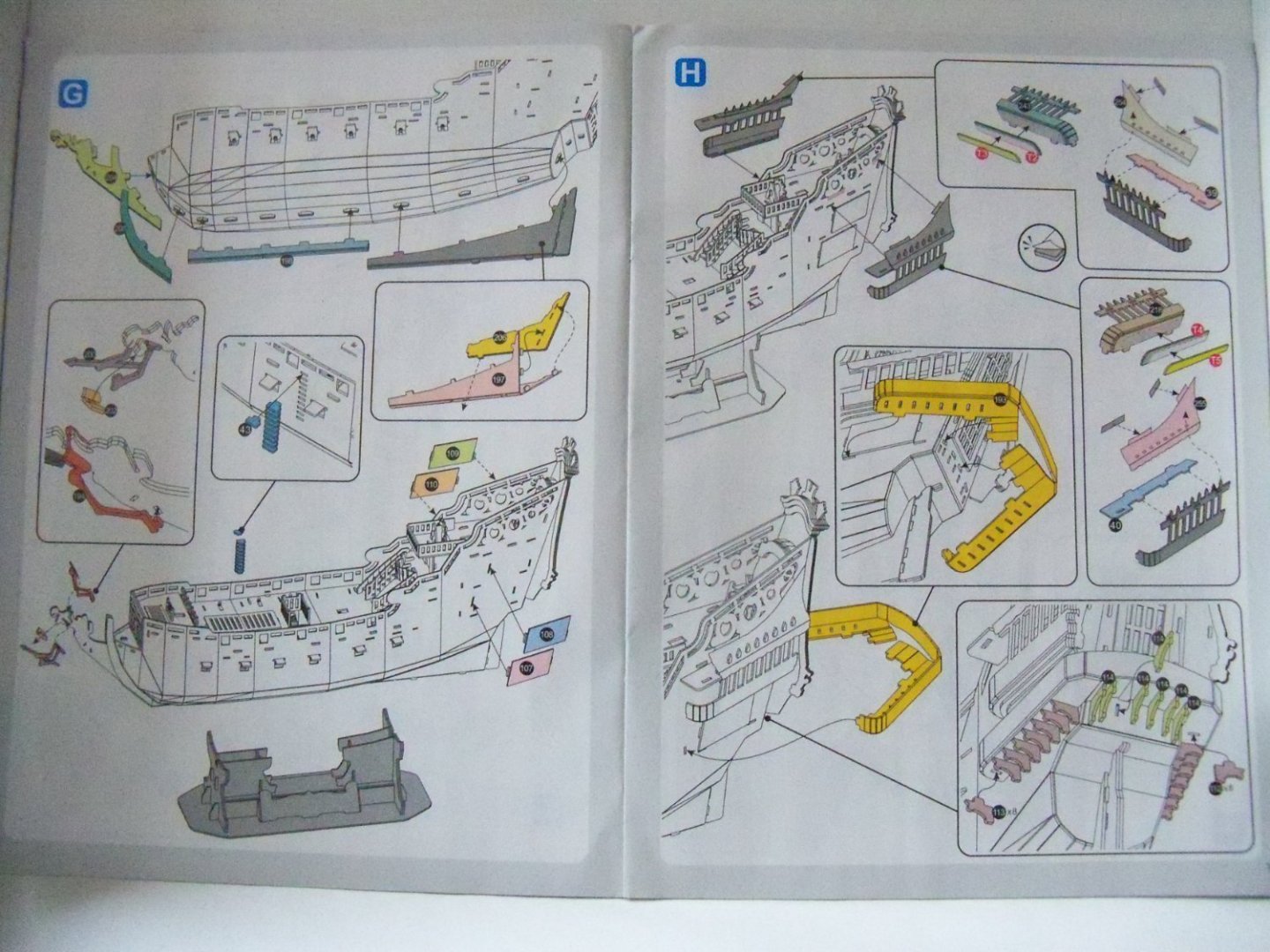
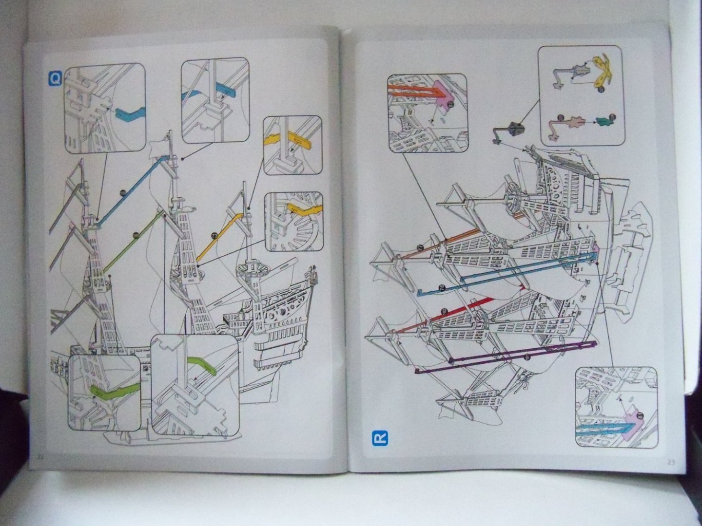
As my interest in jigsaw puzzles and ship modeling is well know by my friends and family, I was presented at X-Mas with this 3D model kit of Queen Anne’s Revenge (Blackbeard’s ship) by my wife's nephew and family. It’s more or less, a combination of my two interests in one box weighing in at a substantial 3 lb. 7 oz. While it is certainly not an accurately detailed rendition of the vessel, it will be my first entry into card models and I look forward to it’s assembly, which judging by the 23 page illustrated step by step instruction manual, (in 7 languages no less) should not be too difficult to complete. There are a total of 391 pieces including the display stand. The vast majority is printed on 15 sheets of 11” x 16.5” pre-punched sheets of 1mm card stock printed in color, but the sails are on 3 sheets of textured paper and there are 22 plastic canons, a small sheet of double sided tape, a card hole puncher, and small sheet of prefinished Mylar to represent stained glass on the rear of the ship. Although glue is not required for construction, obviously if you would like to keep it for display you might like to use some. No tools are required, other than the hole puncher that is included with the kit. It claims to be rated as a 6 in complexity, but not sure if that is out of 10 or what. I tend to believe that according to its estimated construction time of 4 hours it can’t be all that complicated. This kit is designed and manufactured by CubicFun Toys Industrial Co. Ltd out of Guangdong, China and is referred to as an anniversary edition, but I’m not sure if the company has produced an earlier model or if it refers to something else. While there is no indication of scale, the completed size of the model is listed at 29.1” X 10” X 24.4” (or 74cm X 25.6cm X 62cm). As this was a gift, I have no clue about its cost or if it’s a pirated copy of some other company’s product, but from what I can see, it is well produced and nicely packaged. While the model is admittedly more toy like, it is not pretending to be anything other than a 3D puzzle. Overall, I think that it seems to be a good introduction to card models especially for modeling fans that are inexperienced or just want to get their feet wet, so to speak.


-
drilling hole through wire
BETAQDAVE replied to BETAQDAVE's topic in Metal Work, Soldering and Metal Fittings
I’ve been trying to use a small torch for both soldering joints and/or annealing metal. This is the unit below that I’ve bought which burns butane. Unfortunately, it was a little awkward trying to operate with one hand and maintain a continuous flame. First off, a tiny safety lock situated just below the blue trigger button on the right needs to be clicked down before igniting the torch and it was difficult to get at unless you have a long thumbnail. (A small straight edge screwdriver works better for me.) Next, the trigger button needs to be pushed in to ignite the flame, but at the same time you also have to depress and push the chrome lever forward on the side to engage the continuous flame feature. By the time the ignition trigger is released to engage that feature the flame goes out! I’ve even tried it with two hands, but after a dozen more tries the flame went out every time. To add to the frustration, now it doesn’t want to ignite at all. At first I thought it had run out of butane, but after refilling it and depressing the trigger several times, I can hear and smell the release of gas, but there is no longer any ignition at all. At this point it appears that I’ve just wasted about $35 for a defective torch. So I find myself a little leery of ordering another one of the same model. Despite my experience, supposedly 1298 customer reviews gave it 4.5 out of 5 rating and read as follows: Customers like the value, quality and size of the torch. They mention that it's great for the price, an excellent little butane torch and that it makes an awesome cigar lighter. They are also satisfied with size, and ease of use. However, some customers have reported issues with hardness. They say that it doesn't light on the first shot and that the igniter doesn' t work anymore. So, apparently I’m one of those 0.5 out of 5 customers. I guess my question would be whether anyone else here has found a similar product that actually works as advertised. Right now I’m considering the RAVS-2001 model # RBT018 which seems to be a nice one, but then I’ve been fooled before. I'm trying to use it to remake that anchor davit since my drill still refused to make that hole and annealing the wire at this point would melt the solder that is already holding the flats on the end of the davit. If all else fails I may just fake the eye bolt and glue or solder a split ring on the bottom side.
-
drilling hole through wire
BETAQDAVE replied to BETAQDAVE's topic in Metal Work, Soldering and Metal Fittings
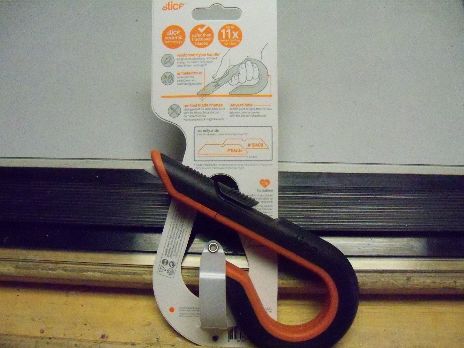
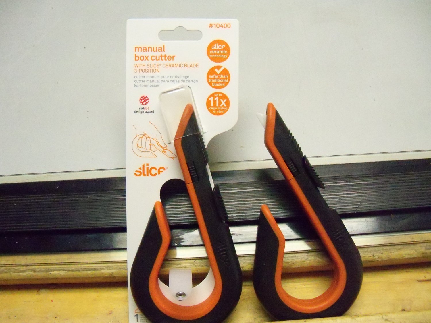
While not a drill bit, the Admiral ordered these ceramic bladed box cutters on line for me. At first I was a little skeptical, but I gave them a try and was pleasantly surprised. I found them easier to grip than a standard cutter and it really cut through heavy cardboard quite easily. Not to mention the fact that despite its sharpness, it was much more durable than I expected and safer to handle. So...I wonder if ceramic bits would have similar properties.

-
drilling hole through wire
BETAQDAVE replied to BETAQDAVE's topic in Metal Work, Soldering and Metal Fittings
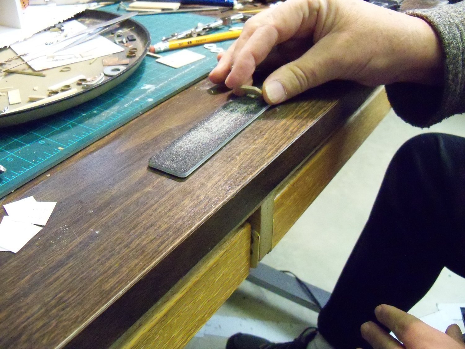
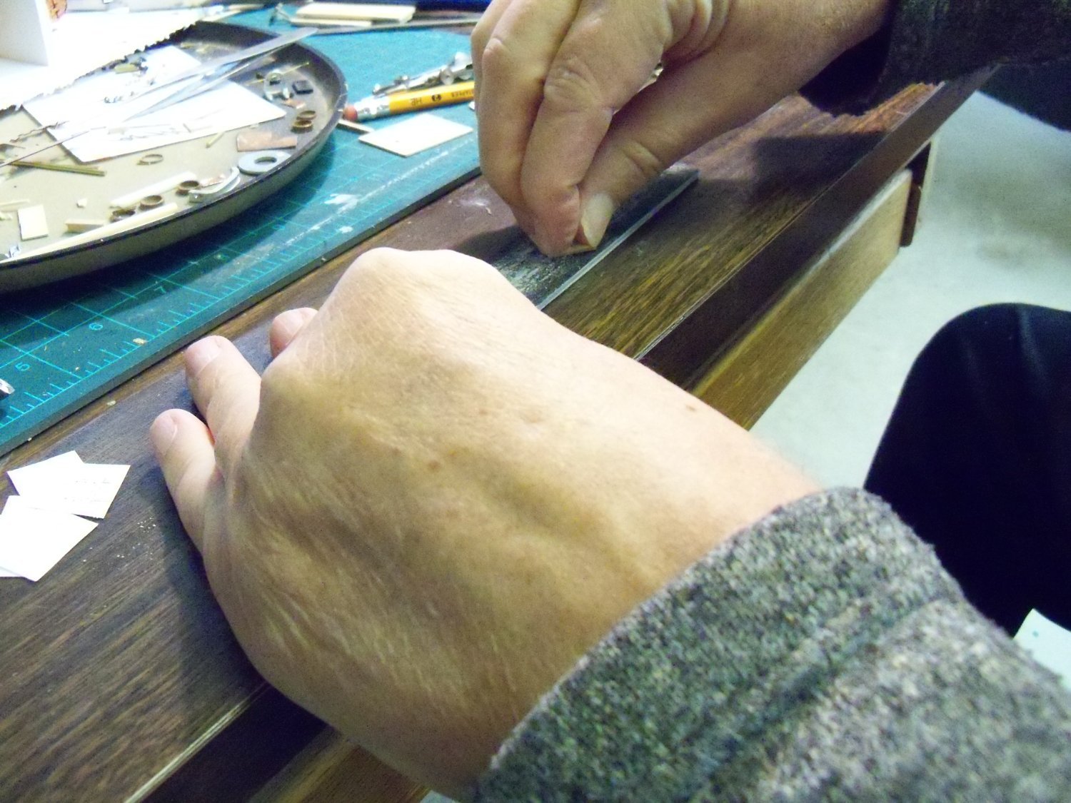
While I did manage, with a heavy needle, to make a center mark and start drilling the hole in the wire with a bit in a machinist’s pin vice, it was very slow going. At first, I was actually making some progress, but after 10-12 minutes or so, the result was a hole less than ¼ of the way through and a broken bit. I took out another drill bit, but this time I left the bit extended just 5mm to reduce the amount of flex and used this battery powered General drill that has low RPMs but high torque. It was easier to maintain a steady alignment with the hole than it was with the pin vice especially since drilling metal usually takes quite a while. However the primary problem I encountered was the fact that the bits appeared to be quite dull. This was evident when I tried to drill a hole for several minutes through a flat piece of brass that barely made a scratch. With the larger sized bits it’s easy to see if they truly are sharp, but unless viewing through a microscope, these tiny bits would be difficult to confirm that they really are. While I have several tiny HSS bit sets from various sources including the original V.F. Rogers Drill Bit Set with the domed cover, I can’t seem to get any better results with any of them. Has anyone here had any better luck with ceramic bit sets or the 1/8” shank bits with the plastic size collars on them? At this point I would be willing to pay a bit more to get better results.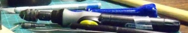
-
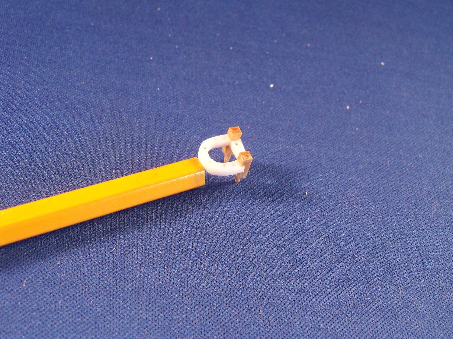
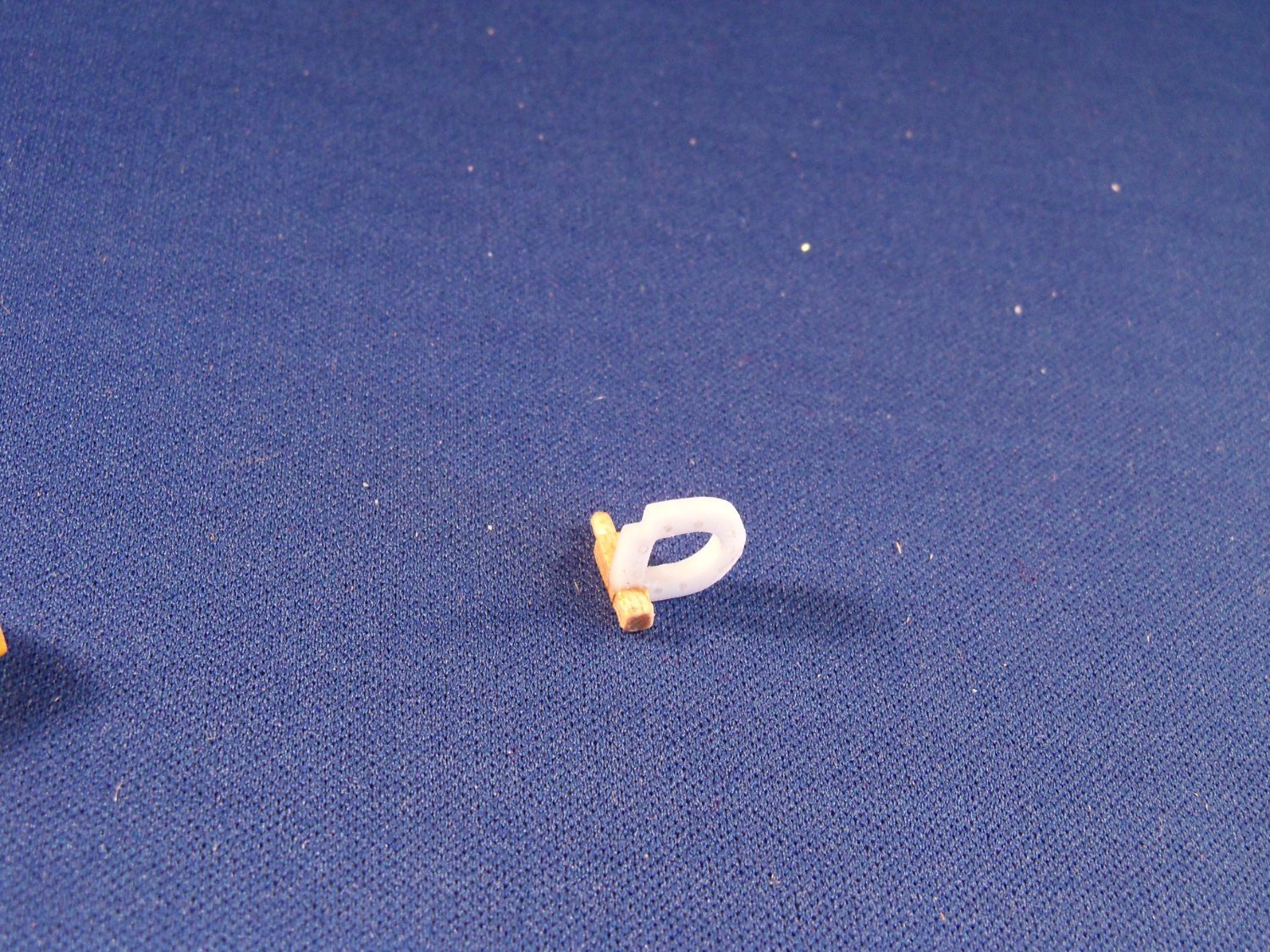
Looking for suggestions about best way to drill a hole through a 1.15mm brass wire for a 0.50mm wire eyebolt as shown below. Also, that 1.15mm wire needs to be widened to about 1.70mm where the hole is.
-
That's true of so much of modeling. Don't experiment with stuff like that on the finish product until you know exactly how it will work or if it even will work! Unfortunately, in some cases once it's done, like it or not, you're stuck with it!
-
The plans provided with my 1:96 scale Phantom from my Model Shipways kit that were apparently taken from H. I. Chapelle don't indicate any of the details that you show on your rendition of the ship. Perhaps they were just simplified for the kit, but it makes it hard to add those details to my version. Did the plans that you are going by actually show these details or do you have another source for them? They seem logical for other similar ships and I would like to remodify my version to include them if possible. On my plans the waterway and the margin planks are shown as one, their were no details shown for the hull counter at the stern, and the cockpit isn't recessed. The book you refer to is apparently only available in an E-book form, but I'm more of an old school hands on researcher that prefers an actual book, so I am still searching for a source for one of them and the blueprints that you are using. Bye the way, your photo images of your log are very well done. I look forward to seeing more.
-
I inherited an old pantograph from my grandfather (circa 1925) that is made from boxwood. I used it once in awhile to enlarge or reduce ship model drawings. Unfortunately there are a lot of screw holes down the center of the beams that would really limit the width of wood to be salvaged. On the other hand, the arms are almost three feet long, so long narrow pieces could be ripped from them. Since I usually work at 1:96 scale I can fashion lots of masts, spars and decking from them. Come to think of it, it's really hard to find such well seasoned straight lumber so perhaps they could used to convert the plastic masts and spars for my 1:87 scale Wanderer to wood.
-
first time rigging - tools and books suggestions
BETAQDAVE replied to Frank Burroughs's topic in Masting, rigging and sails
I heartily agree with his recommendation, as I have three of them. I have very limited grip strength due to muscular dystrophy which makes their spring assisted easy action a blessing and the open handles (as opposed to finger holes) allow me to use all of my fingers to handle it. The micro-tip can get into very limited spaces and the blades are quite sharp! -
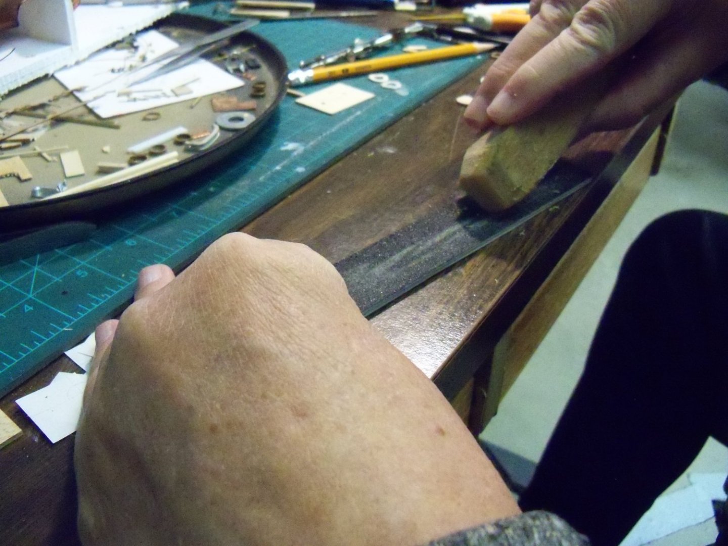
I’ve been away from this log for quite some time now for various reasons including spending time on my Wanderer project and some health concerns, but I’m back now to continue catching the log up with the actual construction. So now that the “easy” part was completed, it was time to make the fife rails. I originally tried using some 1/16” thick maple, but while trying to cut the shape, the part kept splitting along the grain of the wood. So the grain needed to be accounted for by using another layer of wood with the grain going the opposite way. Which is to say, I needed to make my own 1/16” thick plywood! Unfortunately, the thinnest maple that I had on hand was already 1/16”. This seemed to be a real problem until I decided to glue two layers of my 1/16” maple together with the grain running opposite to each other overnight and sand the result down to 1/16”. Sounds simple enough, right? The idea was simple, but to actually do it was another matter all together! Each of the layers also had to be the same thickness to get the benefit of alternate grain directions. I squared up the edges of the slabs and took out the roughest sanding stick that I had (180 grit). Gripping the small pieces with just my finger tips and nails, I started the sanding operation. After the first hundred strokes and measuring the minuscule results, I realized that this was really going to take some time! After each hundred strokes the opposite side was sanded to keep each layer equal and the sanding stick was so clogged with wood dust that it had to be cleaned up with my Magic Eraser shown below before continuing. As it turned out, each side of the two wood slabs required over 1,000 strokes to get to the required thickness. Once I got going, my stubborn streak took hold of me, and I refused to give it up, but ohhh, my aching fingers!!! I drew a template to scale on plain white paper for the fife rail and glued it to the topside of the slab with rubber cement. But then despite going through all of that work, I found that drilling the small holes for the belaying pins still caused the layer with the grain running the narrow direction to fail. I also had trouble when sanding up to the lines on the paper template because the template would deform or pull loose. Thinking that it was because of the cement, I tried using white wood glue, but it did the same thing. Finally, I gave up on using both the plywood and the plain white paper template, since the rails will be painted anyway. So I dug up some 1/16” thick scraps of plastic for the rails. I used drafting vellum this time and redrew them which held up much better to both the glue and the sanding. Since both the plastic and the paper were very slick, I had to machine it as if it was metal. So to keep the drill bits from wandering, a sharp metal awl was needed to dent the plastic for all the holes. The first step was to drill a 13/64” hole to give me the inside radius of the front edge of the rail. After that, I used some round and square files to clean out the rest of the opening for the masts. Two 3/64” x 3/64” notches were filed in the back corners to fit into the post notches. A 0.71mm bit was used to make the through holes for the belaying pins. (That’s 9 holes for the main mast and 8 for the fore mast as shown on the plan detail.) The fife rails were then turned upside down and a pair of 0.69mm holes were drilled for the top pins of the spindles. These were drilled just short of going all the way through the rail. Finally, the rail was filed down to the outside edges of the template. After pealing off the remnants of the template the assembly was test fit together as shown below. Once one of the posts was glued to the rail with thin CA, it was set aside to dry overnight. The next day the upper portion of the post was filed to its final shape as shown below. Now the other post was given the same treatment. I was a little careless using the thin CA to join the pieces as it had spread a bit too far, so the four closest holes to the posts needed to be cleaned out, but it was ready for painting. I wasn’t sure just how badly the Model Shipways paint would work in my spray painter, so I tried something a little different this time. I mixed up a small amount of light buff deckhouse paint with six drops of paint to six drops of water. Once mixed, I gave the parts four coats and used a blow drier and light sanding to speed up the process between coats. Actually, the Model Shipways paint I have doesn’t seem to be a very finely ground pigment as it definitely needed sanding between coats, but then my first order of their paint had several jars that were more like dried up hockey pucks than paint inside. On close examination I could see that they still needed a good sanding! How I miss the discontinued Floquil paint!! Although the spindles included with the kit for the fife rails were metal, they were still quite fragile to work with, not to mention the fact that just holding on to them is quite a chore. In Chucks’ practicum the spindles appear to be much heftier than the 3/64” ones included with my kit, because in that photo from his article shown previously, they appeared to be about the same diameter (3/32”) as the thickness of the posts. I thought about trying to chuck some 3/32” thick brass wire in my drill press to see if a decent copy could be turned with files and sandpaper, but for now I will try working with the spindles that came with the kit. Both ends of the kit spindle pins first needed straightening before they were filed smooth. These were painted with the same procedure and at the same time as the fife rails. Finally with the arrival of the warmer weather, the one hang-up of fixing my table saw was finally taken care of. One of the rubber caster wheels on the mobile base was crushed so I couldn't pull the saw out to use it. I enlisted the help of one of my neighbors to make the repairs, since I am not able to get down to the floor anymore to do it myself. Although I had some 2 1/2” caster wheels on hand, the wheels on the base were 3” diameter. The smaller wheels still fit with enough clearance, so we pulled the two wheels on the front of the saw and replaced them with the smaller ones which would least leave it balanced for moving the saw. Since those two front casters have some leveling screws alongside them that take the weight off the wheels when the saw’s being used, I thought that would be good enough for my needs. I still needed to dull the sheen of the copper plates on the hull anyways, the ship was removed from the base so I could trim and finish the base board. That took longer than I thought it would just to readjust the saws alignment. Maybe due to the fact that it wasn’t used in over a year or two? Once the board was trimmed and sanded, the ends and edges were given two coats of Minwax light oak finish while I gave the walnut pedestals a couple coats of hull black paint and set them aside. After everything was dry, they were all given three coats of satin finish polyethylene, lightly sanding between coats. While waiting for things to dry, I smoothed over the copper plating on the ships hull to make sure there weren’t any loose edges. I brushed some sun tanning oil on the plates and set the ship upside down in the sun for a couple of days. Then I gave the surface a rub down with a soft cloth and finally gave it two coats of polyethylene to seal it.


-
Pin Vise vs. Hand Vise?
BETAQDAVE replied to Balclutha75's topic in Modeling tools and Workshop Equipment
Same problem here Mark. -
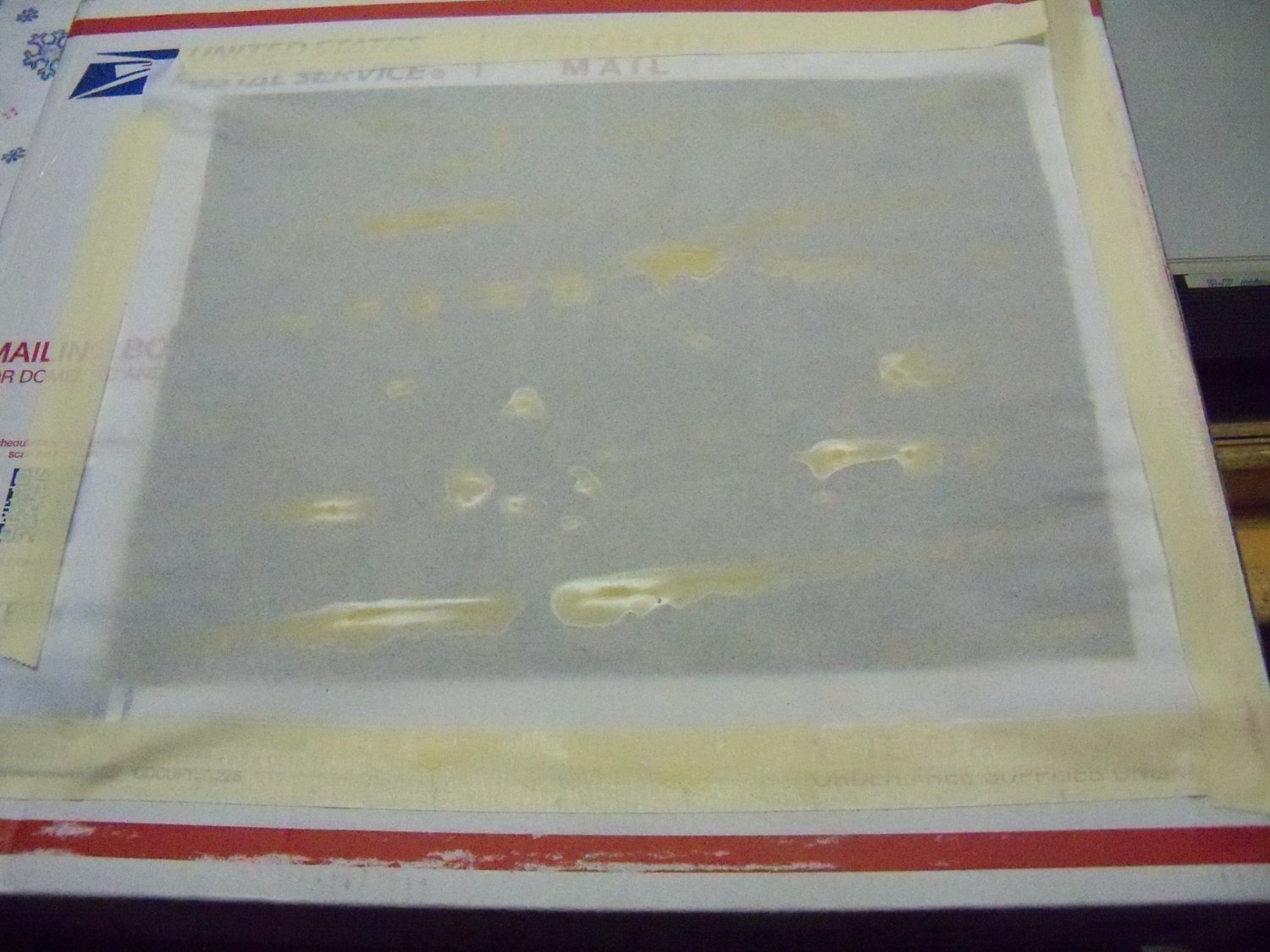
This is a question regarding your simple man's guide to small scale sail making. Do you remember what ratio of PVA to water you used for the Witches Brew sail wash? You described it as being the consistency of milk, but would that be skim, 1%,2% or whole milk? I'm making sails for my 1:96 scale Phantom pilot boat and when the material dried overnight, the mix apparently pooled in the low spots and drained from the high spots as shown below which made the finish very uneven. I'm not sure if it was my mix or the light weight drafting vellum paper that I used. I don't know for sure, but maybe I should have used your hurry up method of using a hair drier to speed it up. As light as the vellum paper was, maybe it was still a bit too stiff. I found some very light weight tracing paper that I will try next.

-
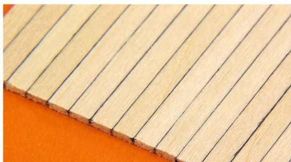
Well Roger, for some more authentic-looking (because the grain varies from plank to plank) wooden model ship decking or board-by-board siding go to Micro-Mark. Black glue is used to bond individual planks of basswood together side-by-side in sheets 3 inches wide x 22 inches long x 0.050 inch thick, perfectly simulating the look of board-by-board construction without the tedious, time-consuming hassle of doing it yourself. Planks widths are available in 1/16 inch, 3/32 inch, 1/8 inch, or 3/16 inch. The price is around $25 per sheet. Have a look here.
-
Good question! The plans for the MS Phantom show one of these also. No details are provided there either.
- 399 replies
-
- 2
-
-
- cutty sark
- revell
- (and 2 more)
-
I just went through this posting and happily found out that it wasn't due to something I did on my end. I still remember the old Computers for Dummies manuals which emphatically declared that your computer won't blow up if you push the wrong button. Yes, but other bad things definitely could and in my case did! 🙈🙉🙊
-
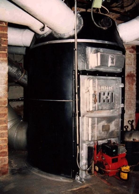
Speaking of Dodgy furnaces: My maternal grandparents lived in a three flat building built in the early 1920’s. They had a coal burning gravity hot air type octopus furnace similar to the one below, but without the red accessory that was later added on at the bottom. There was no fan to force the air up since the hot air just naturally rose through the ducts. Each heating vent had it’s own duct that attached directly to the furnace and made it look like an upside down octopus. The building had more than a dozen heat ducts and due to that maze of ducts and the large coal bin, it took up most of the basement. The basement ceiling was also about twelve feet high to allow some clearance below the ducts. Access to the basement was by a 22 rise L shaped stair with a landing half way down that was in a separate room partitioned off from the furnace room with a large heavy steel door, with a closer that always slammed with a resounding bang! I say that because, to a group of young kids ages 3-5 it made us all jump whenever it closed behind leaving us in what seemed like a dimly lit dungeon. Eventually we became more adventurous and started going down there to play, but our parents began to worry about us getting into mischief way down there, so grandfather, who always was a bit of a prankster, teased us that there was a green eyed monster that hid in the coal bin sometimes to discourage our interest in going down there. At first, we began to think that he was just kidding us since we never saw it and started to go down there again anyway. So grandfather decided that now he needed up his game a bit. Taking a pair of flashlights with some green cellophane covering the lenses, he turned them on and placed them in the coal bin just before our next visit. So when we were about to go down to the basement, he told us that he had just seen the green eyed monster in the coal bin earlier and we probably shouldn’t go down there. Of course we all though he was just teasing us again, but he said that he better go down with us to see if it was still there. Well, we had just entered the furnace room, he ushered us inside and closed the door with a bang which set us a bit on edge to begin with and we looked around somewhat nervously and said we didn’t see anything. Now the basement, with its one small window and a single light bulb, was pretty dim down there to begin with, but he suggested that we might be able to sneak up on it better if we turned out the light,. So he did. Walking over to the coal bin he opened the door a bit and we all looked in. Lo and behold, there was this pair of bright green eyes starring right back at us!! 👾😱😲 We all instantly made a panicked run to the door and flew up those stairs as fast as we could! For years after that we never went back down there unless grandfather checked it out first.
-
So I guess that professional golfer John Daly styling would not be accepted?


-
Concerning post #49 I think that something like this has been developed, but his aim would be a little iffy.

-
That's so he can protect himself from being poked in the eye from the projecting spars and rigging.
-
But, on the bright side, he is wearing safety goggles!