HOLIDAY DONATION DRIVE - SUPPORT MSW - DO YOUR PART TO KEEP THIS GREAT FORUM GOING!
×


BETAQDAVE
-
Posts
5,386 -
Joined
-
Last visited
Content Type
Profiles
Forums
Gallery
Events
Everything posted by BETAQDAVE
-
 With Christmas just around the corner, the Admiral has been stocking up on wrapping paper. (Truth be told, she does this all year long.) She buys the paper wrapped around paper tubes so the gift wrap doesn't have visible fold marks. Most of the tubes are over 24" long, come in various diameters and are easily cut to the length that you desire. Since the tubes normally just end up in the recycle bins when the paper is used up anyway, why not repurpose them as storage tubes for your wood strips? Which makes them basically free!😁
 -
I noticed that you made a margin plank for the cockpit, but neither the original 1/8 inch scale plans nor the plans for this 1/4 inch scale version call for one. The Victory 78 version of the Phantom does show one. Are you following his version of the ship or did you find another source that indicates that feature?
-
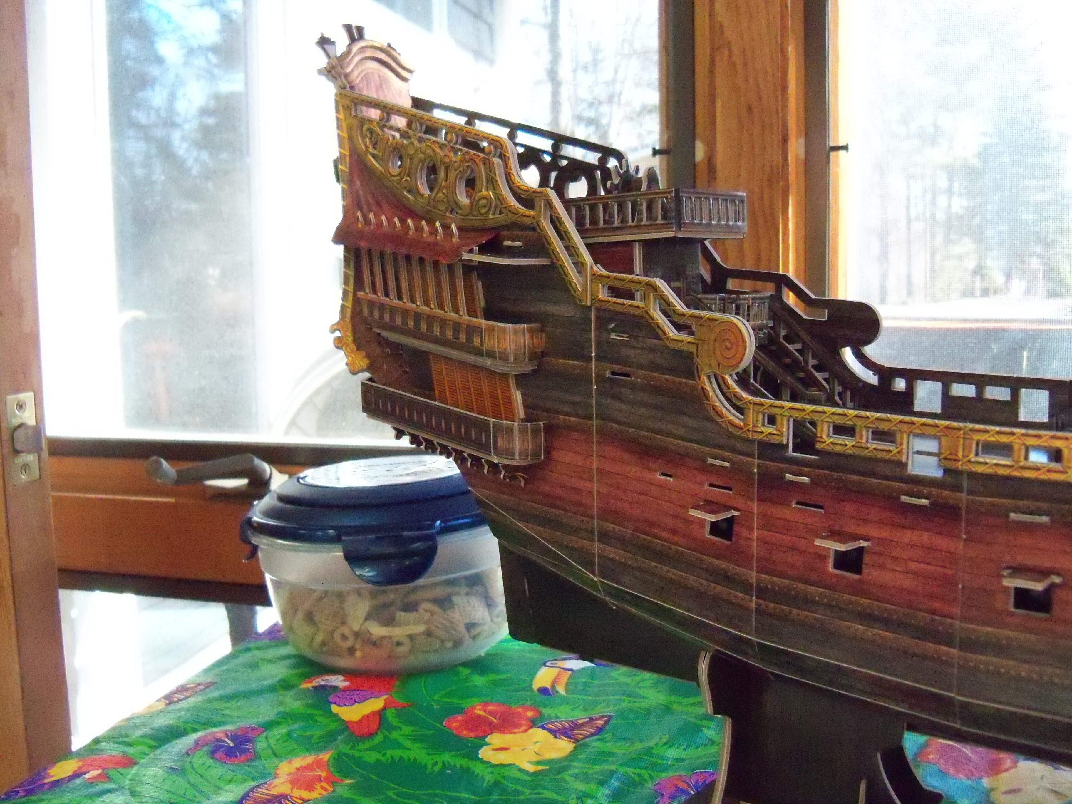
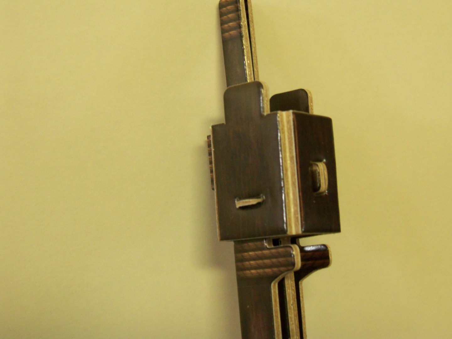
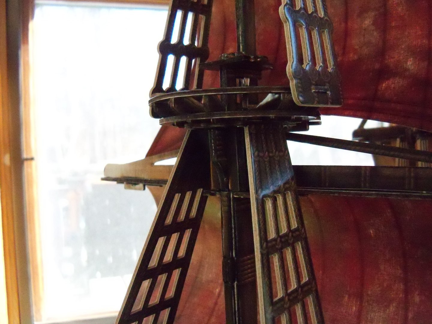
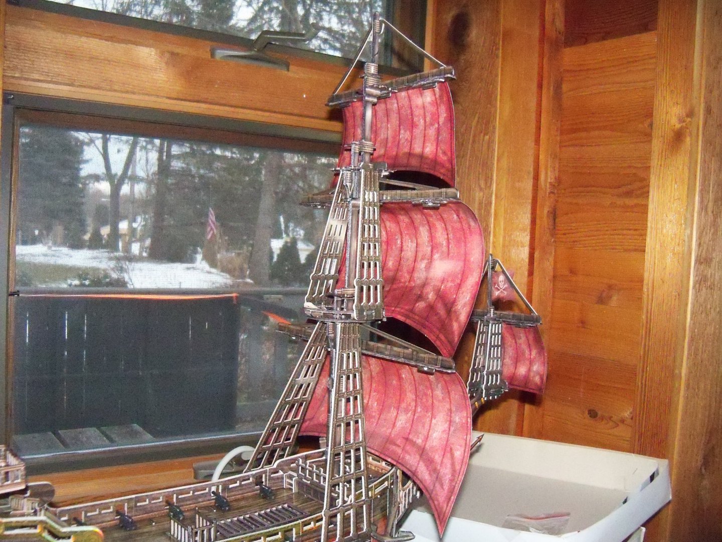
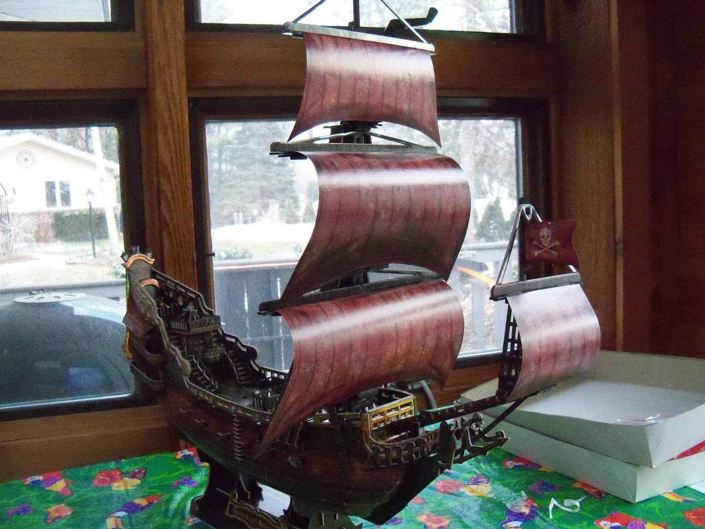
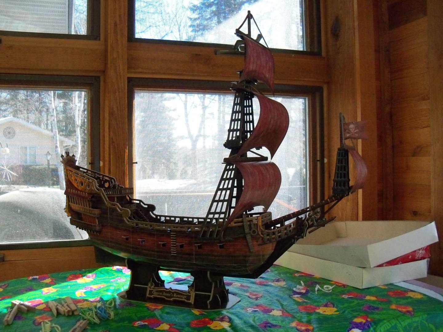
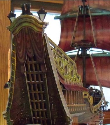
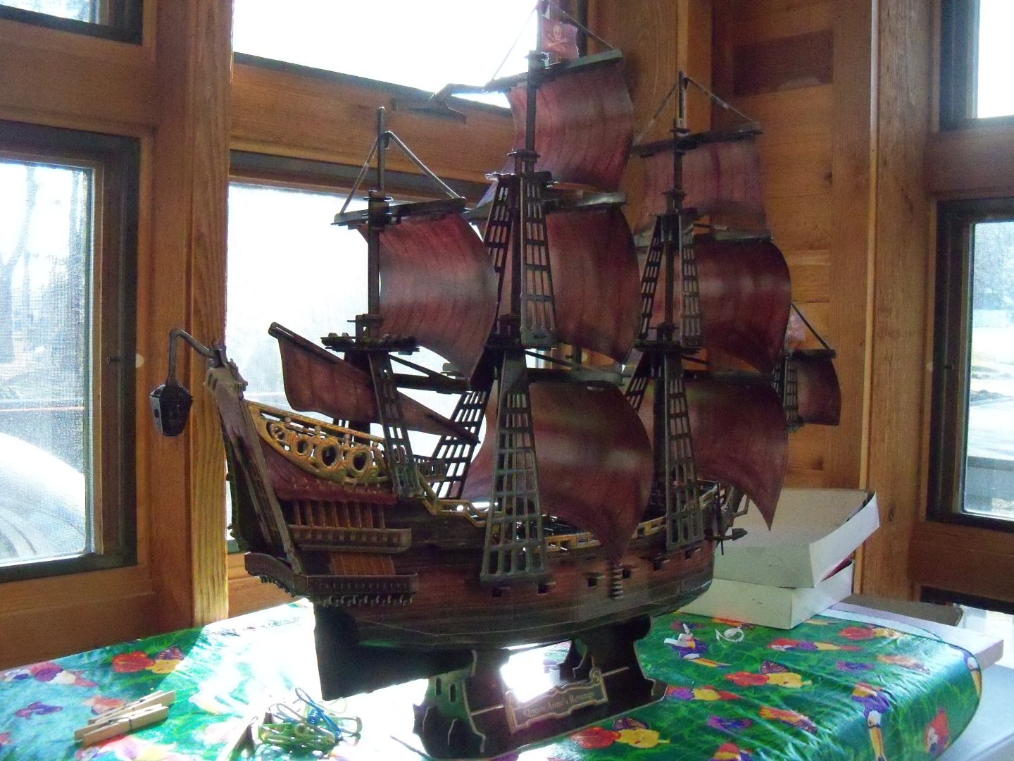
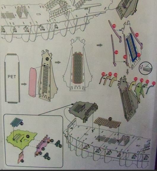
Well, it’s been a while since this was updated, so I’ll get right to it here. Remember quite a bit earlier in this log on step E when I mentioned that I had installed the gilded transom trim on the WRONG side of the transom? Well, this is when I finally realized my error! My confusion was due to the fact that the trim piece (#T18) appeared to be a set of drapes for the transom window which happens to lean out away from the ship. It didn’t seem right, as that would just make them hang loose out away from the ship. Since all seven transom trim pieces were adhesive backed, I had to separate them very carefully with a long thin blade and reapply them with some of the remaining double faced tape. The build was continued with step L1 which covers the foremast assembly as shown below. Part #148 was folded over for a two ply inner layer of the lower foremast. The outer layers of the mast are formed by part #149 which has parallel fold lines and two slots. This is folded around the inner layers of the mast with those two slots engaged with the two tabs on the inner layer of the mast. A two tabbed clip (# 167) slips into a slot in the front side of the mast just below the top to hold these parts together as shown below. Then part #150, which has a slot on the bottom edge engages yet another slot on the top side of the assembled mast. This is folded around the mast engaging the two projecting tabs of (#167) which now serve as cheeks for the top. Now the lower shrouds (#188) were slipped over the projecting top of the lower mast and the two projecting tabs from the cheeks below. The shrouds were folded down and the pair of tabs at the bottom were set into their corresponding slots in the channels (#182 & 180). I deviated a bit here for the installation of the foremast top (#153) by assembling the mast top by itself first, as it was easier to do on a flat surface. Twelve supports (#183) for the top edge ring (#154) were inserted into their respective slots around the perimeter of the top and the ring was set into place with the two tabs facing to either side. Once those were all in place, four additional tie down cleats (#189) were added to the remaining slots in the top. This assembly was then installed on top of the lower foremast with the slotted tab to the front for support of the sail. Here is a view of the completed foremast top. Next, the fore topmast (#158) was assembled similarly to the lower fore mast, less the outer layer, with another two tabbed clip (#159) slipped into a slot in the front side of the mast just below its top. Then, the cheeks (#179) were folded around it, which also has a slot on the bottom that engages yet another slot on the top side of the mast. Here is a view of the completed cheeks and fore topmast top. Another two tab mast cap/clip (#155) was slipped into a slot in the bottom backside of the fore topmast. The heel of the whole assembly was then stuck into the front slot of the foremast top with the slot on the cap onto the projecting mast below. The shroud portions of the fore topmast trestle trees (#190) were folded down and the slots are engaged to the projecting tabs on the sides of the top, with the rear slot of (#155) set onto the projecting top of the lower foremast. The fore topgallant mast (#165) was folded over and clipped into the slot just below the flag pole at the top with part #157 and clipped into the slot at the bottom with part #168 which also has a slot for attaching to the projecting topmast below. L2 continues the foremast assembly by attaching the sails. Oddly enough they start with the fore topgallant sail. The yard is actually a combination of two parts. Part #173 is the lower portion and part #169 which is the upper portion that includes the lifts. The sail (#244) is sandwiched between the two of them with three slotted tabs of the top portion passing through corresponding slots in the sail and lower yard. Part #s 166, 172, and 174 lock this assembly together. The directions for attaching the sail to the ship was a bit awkward, so I changed it slightly by attaching the sail prior to the yard by passing clip #171 through the slotted tab at the bottom of the sail and then into the corresponding slot in the front of the shroud top #190. This in turn is locked in place by part #170, that is passed through its slot at the bottom. Then the yard is attached to the topgallant mast by slipping the slot in the lower yard into its’ corresponding slot on the front side of the mast just below part #157. Lastly, there is a small tab on the front side of the top gallant mast that a slot at the peak of the lifts is attached to. I found that doing it the way suggested in the directions made it too difficult to attach the bottom of the sail. I guess my fingers were just too thick to get at the fittings. All of that may sound rather confusing, but the illustration is very helpful. The fore topsail is quite similar, combining part #s 184, 253, 181,185, 186, and 187 for the sail and yard. The slot in the lower part of the yard is slid into the corresponding slot. The procedure for the fore topsail is covered in step L2 and step L3 covers the forecourse. Both of those are similar to step L1. I deviated from the instructions somewhat here. Before completing the other masts, I mounted the foremast and spritsail topsail assemblies on the ship. The four-ply mast fit into its hole in the forcastle deck and the tabs on the shroud channels fit into their slots in the hull. Here are some views of them in place. But wait a minute here…... Remember earlier in this log, way back on step E, when I mentioned that I had installed the gilded transom trim on the WRONG side of the transom? Well, this is when I FINALLY realized my error! I think that my confusion was due to the fact that the trim piece (#T18) appeared to be a set of drapes for the transom window which actually leans out away from the ship. That didn’t seem right, as it would just make them hang loose out away from the ship, so I installed part #’s 52, T24, T16, T17, T20 and T19 on the outside and T18, T21, T22, and T23 on the inside as shown below instead. Since all ten transom trim pieces were adhesive backed, I had to separate them very carefully with a long thin blade. After all of that, they were reapplied where they belonged as shown below. Steps M1, M2, and M3 cover the main mast and its’ sails. With the exception of attaching flag #249, this is also similar to the foremast. The flag employs a small strip of double faced tape between it and the flag staff portion of the main topgallant mast which is folded around it and secured with clip #66. Once the main mast assembly was completed the heel of the mast was passed through its slot in the main deck. The three tabs of the channels were inserted into their corresponding three slots in the sides of the hull. Moving on now to steps N1 and N2 which cover the mizzen mast and sails, where the only significant difference is the addition of a lateen yard and sail. The sail (#247) is sandwiched between the yard (#117) and two cleats (#129 and #130). The assembly's yard has a slot in the center that mounts to a tab on the side of the mizzen topsail yard (#128). Once this mast assembly was done, its’ heel was inserted into the slot in the upper rear deck, and the single tabs in the shrouds were stuck into the slots on the roof/channel just ahead of the gallery canopy previously installed in step H. Skipping ahead a bit, I assembled the stern lantern shown on step R. The support bracket (part #225) has a slot in the bottom that receives a slot in the top of part #226. The lantern itself (part #227) is folded around the end of those two parts, with its’ eight slots joined to the corresponding tabs. A slot in the top end of the lantern bracket clips into a matching slot at the peak of the transom. So, here are some photos of the ship as it stood at this point. With the exception of the spar lifts, the is no other running rigging included with the kit. I will be covering the remaining three steps (P, Q, and R) which is the the installation of the remaining standing rigging. Without a doubt, it's taking much longer to write up this log than to actually build the model!


- 9 replies
-
- 3
-

-
- Queen Annes Revenge
- CubicFun Toys
- (and 1 more)
-
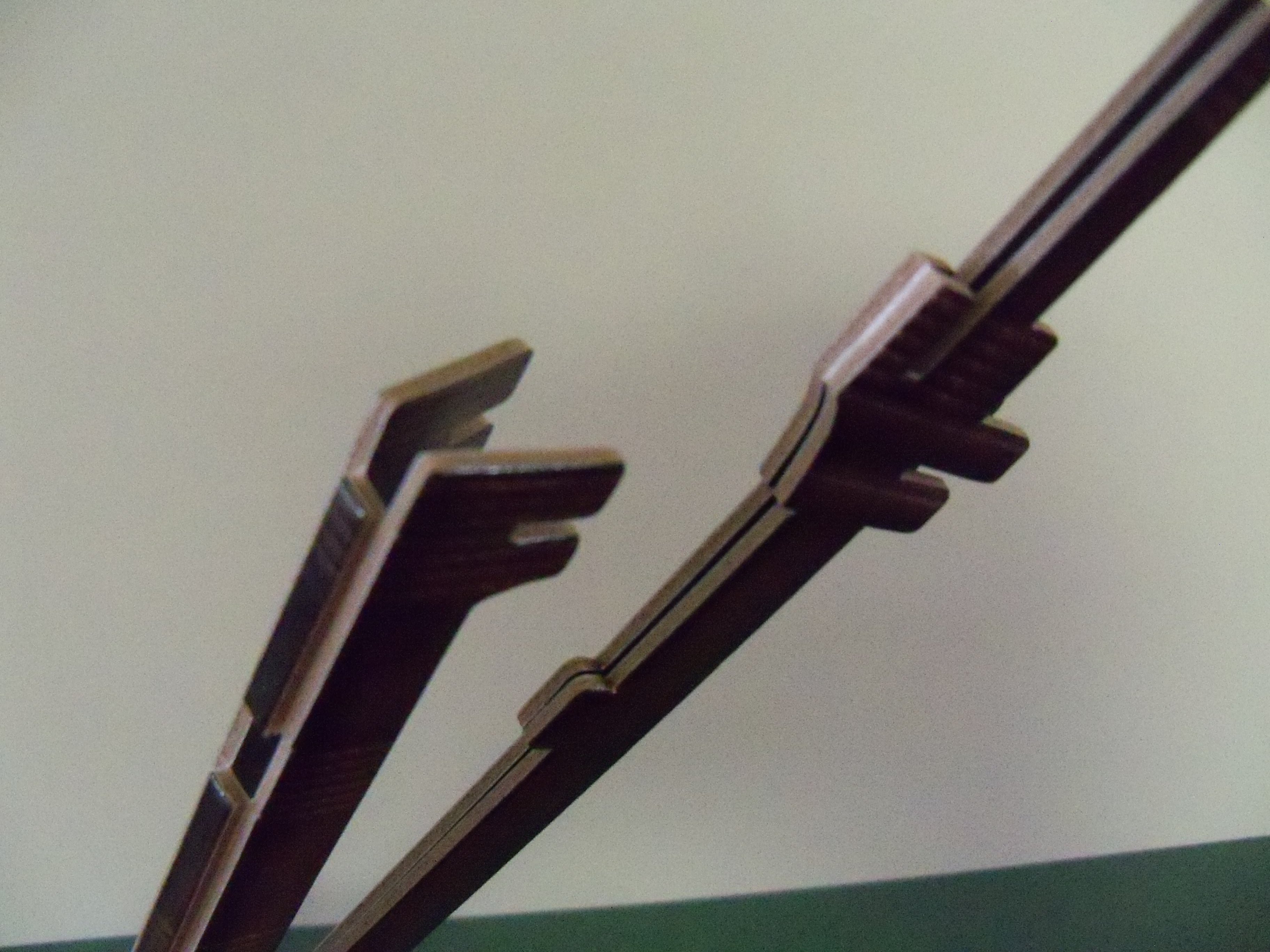
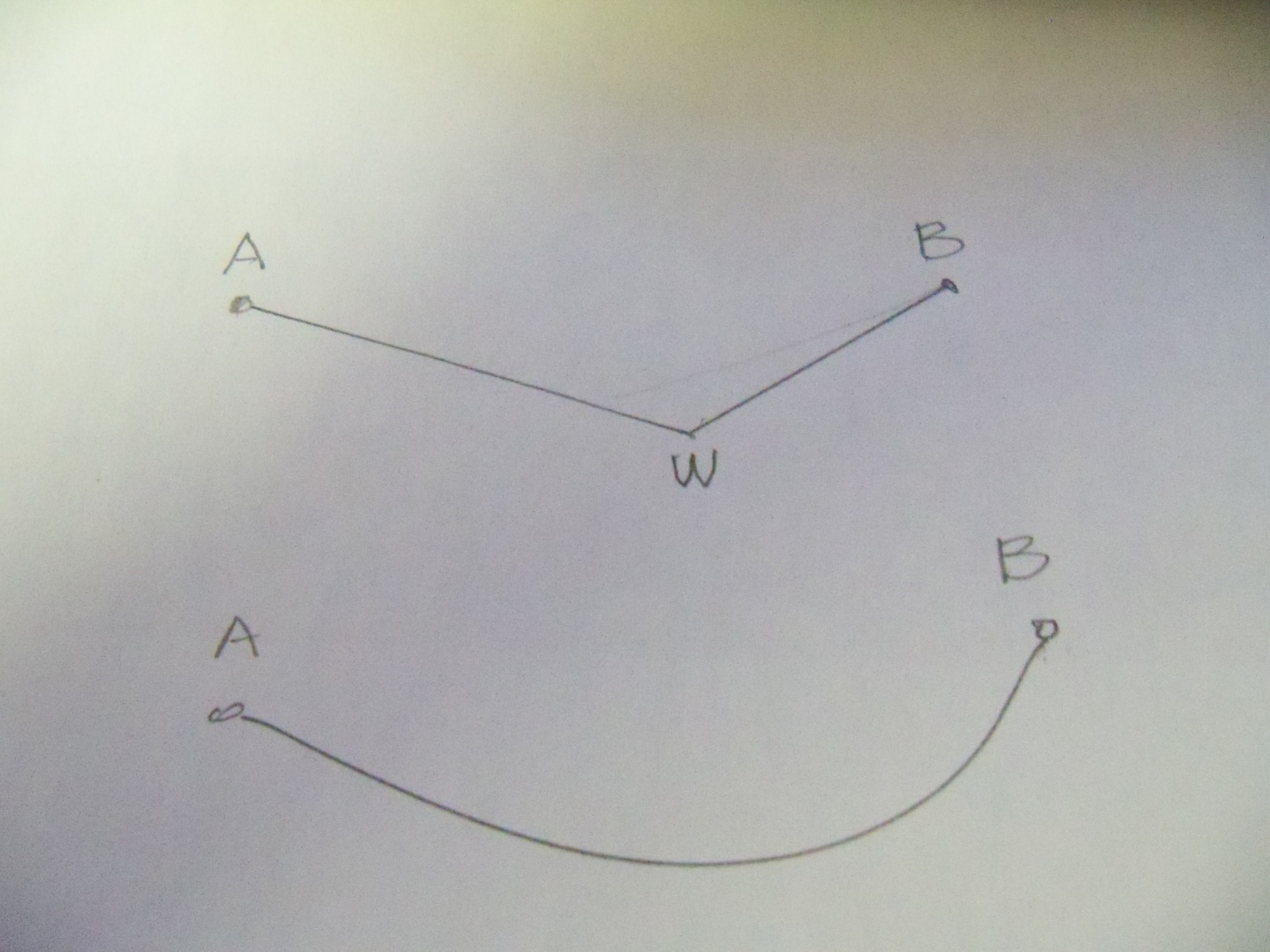
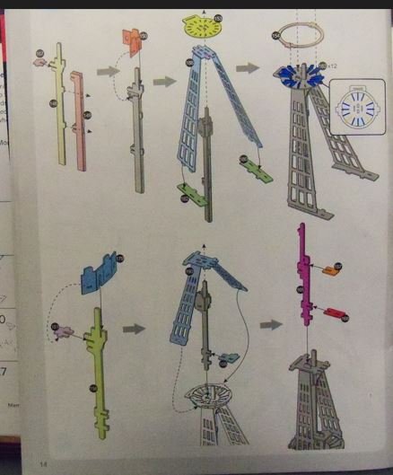
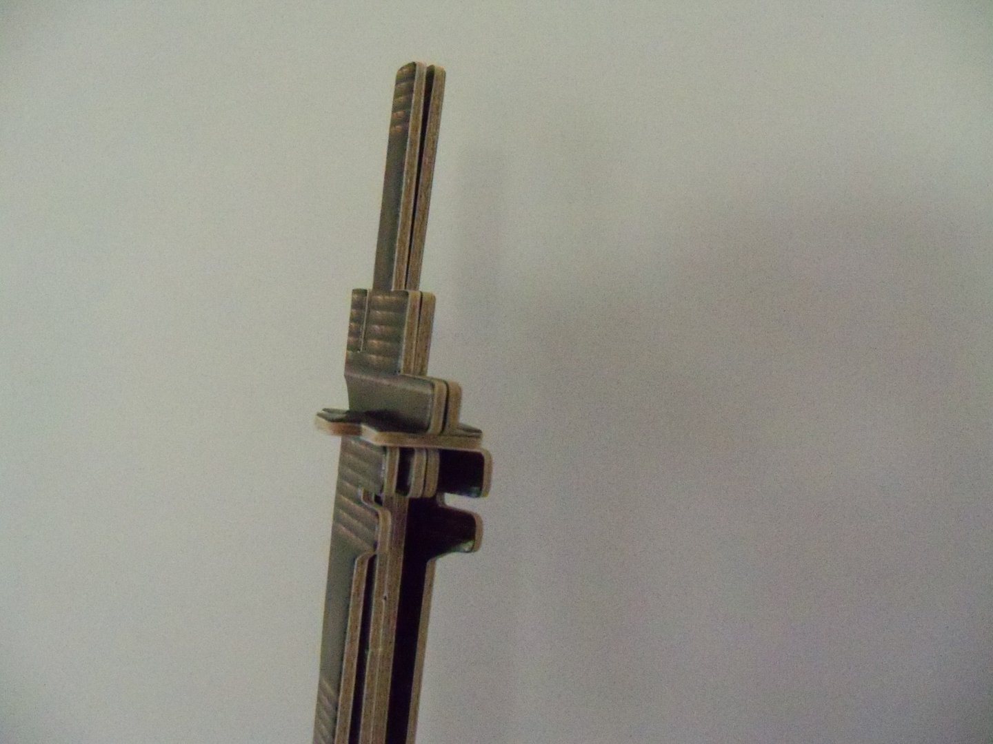
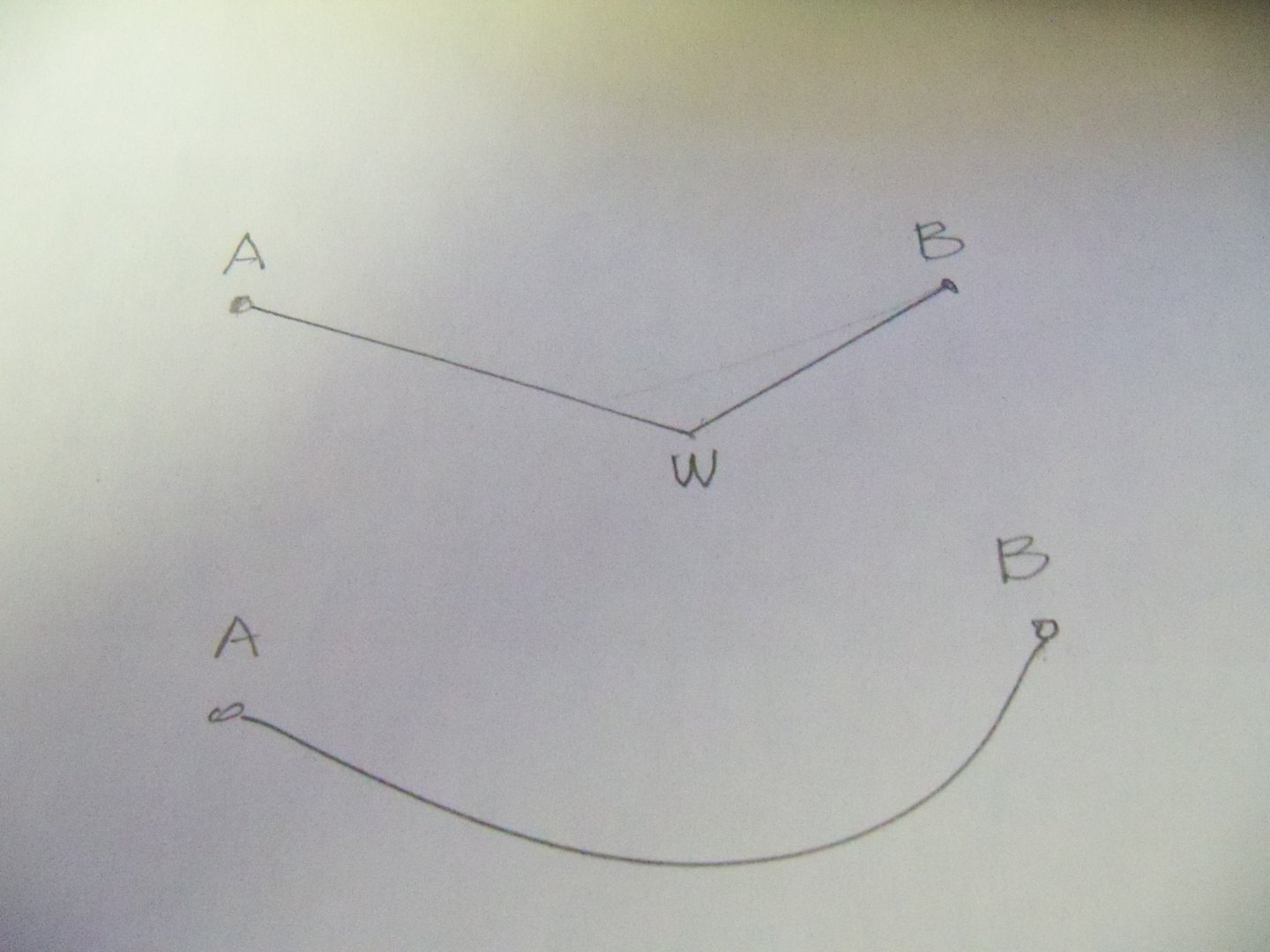
The primary problem with small scale models is that the rope that we use, has little or no heft to it and won't drape realistically. The problem with just hanging a single weight on the line, is that you end up with the example at the top, rather than the one below which would be more true to life. And, unfortunately, it's very noticeable when you have pairs of lines exiting from blocks.
-
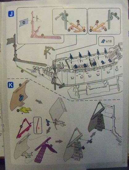
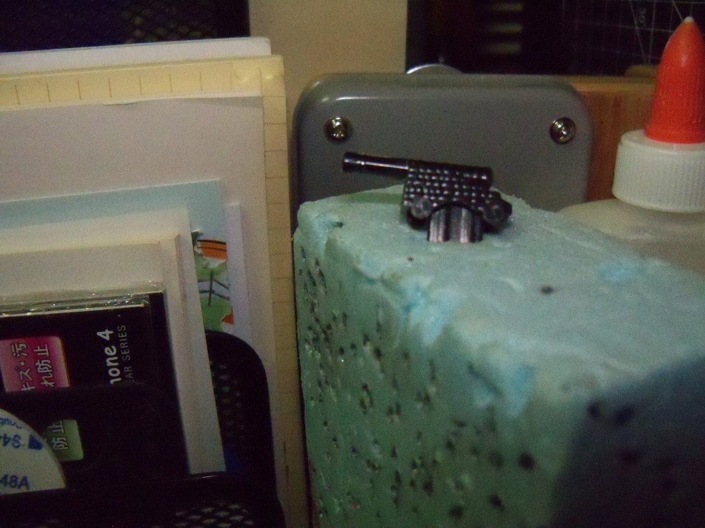
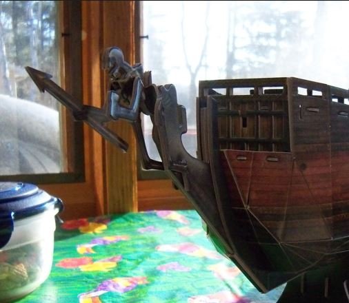
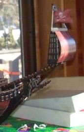
Step J and K shared page 13 of the instructions as shown here. Step J covered the remaining deck fittings and the bowsprit. While setting the remaining ten canons on the main deck I found one thing a bit odd about them. If you look close to the photo below, you can see that their carriages were apparently made from bricks! Next, two large anchors constructed from four parts each were shown in a pair of subsets. Both port and starboard anchors were the same except for their stocks which had their ropes on opposite sides. Each one was only supported with a single tab in a slot on the forecastle deck. Apparently, they intended to just let the other end hang loose, but I added a dab of glue where they touched the side of the hull rather than risk a mishap. Then the combination bowsprit/sprit topmast (part #119) was assembled by folding it in half, with the printed paper flag (#249) sandwiched between the layers at the flag staff and held in place with a piece of the double faced tape. Passing through a gap in the upper stem, the heel of the bowsprit was set into a slot in the face of the forecastle. And lastly, the bobstay (part#196) was secured with one tab stuck in a slot at the end of the bowsprit, passed between the arms and legs of the figurehead and into another slot in the stem by his foot which completed step J. This kit employed a rather unique mounting system for the ships sails. The sails had a folded over portion that included two or three tabs with integral slots at the top, while the bottom had a single tab with an integral slot in the center. The upper portion of the corresponding yards also had matching tabs with integral slots that were passed through both the slot in the sail and the slot in the lower portion of the yard. All of those tabs had locking clips to tie them together. Since there was the bare minimum of running rigging on this ship model, the bottoms of the sails required a similar approach. The tab/slot at the bottom of the sail was aligned with a matching slot at their mast top. Another tab/slot key was passed through both the slot in the sail and the slot in their mast top. All of those tabs had an additional locking clip to tie them together. So section K began with the assembly of the top spritsail. Taking the first printed paper sail (#248) in hand, a tab/slot key (#97) was passed through both the sail slot and the slot in the bowsprit top (#94). Then a locking clip (#95) was used to tie it together. The upper portion of the spritsail yard (#98) needed to have a slight bend where the yard lifts joined with it. Once done with that, the two tab/slots were passed through both the sail slots and the lower portion of the spritsail yard/shrouds (#80). Locking clips (#79 & #90) secured the joint. The shroud portion of (#80) was then bent down and clipped to the tabs on the sides of the bowsprit top (#94). To finish step K, the assembly was mounted with two slots slipping into corresponding slots on the mast and a pin at the top of the flagstaff. Here’s the bowsprit and spritsail shown completed below from these two steps.
- 9 replies
-
- 4
-
-
- Queen Annes Revenge
- CubicFun Toys
- (and 1 more)
-
Not a problem here. I've known plenty of "English" speaking people here in the U.S. who have yet to master it.
-
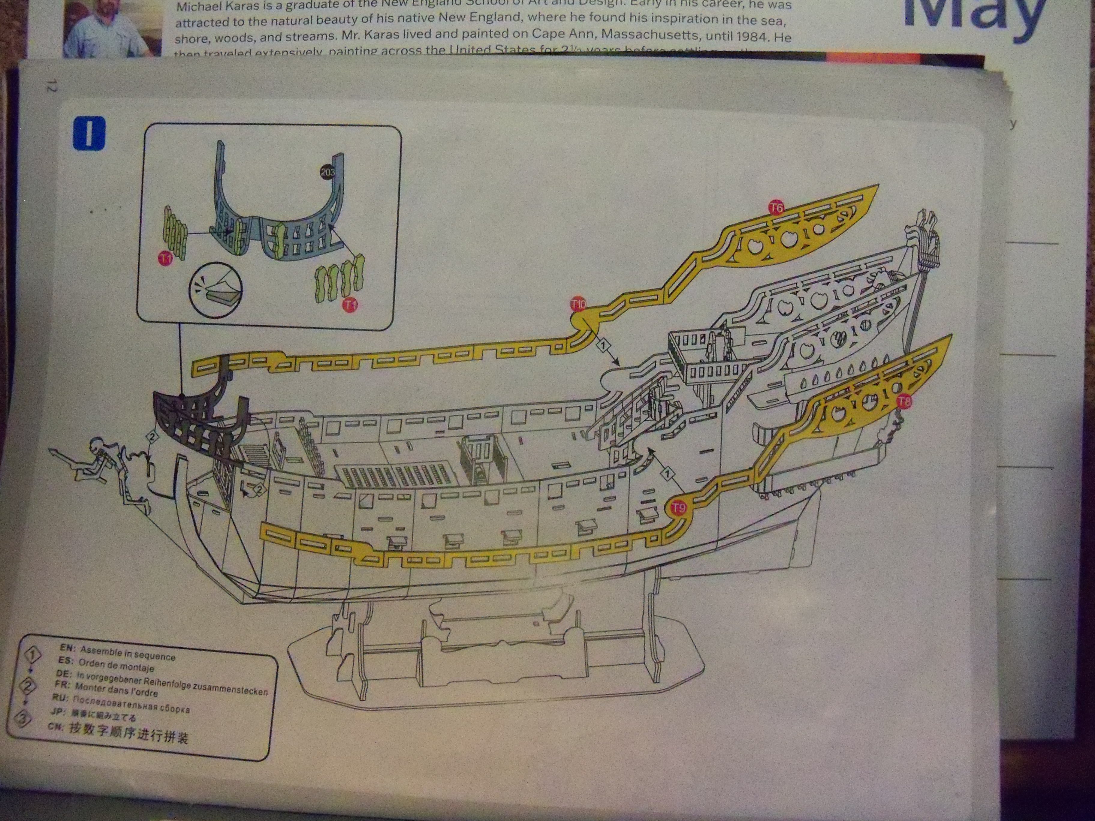
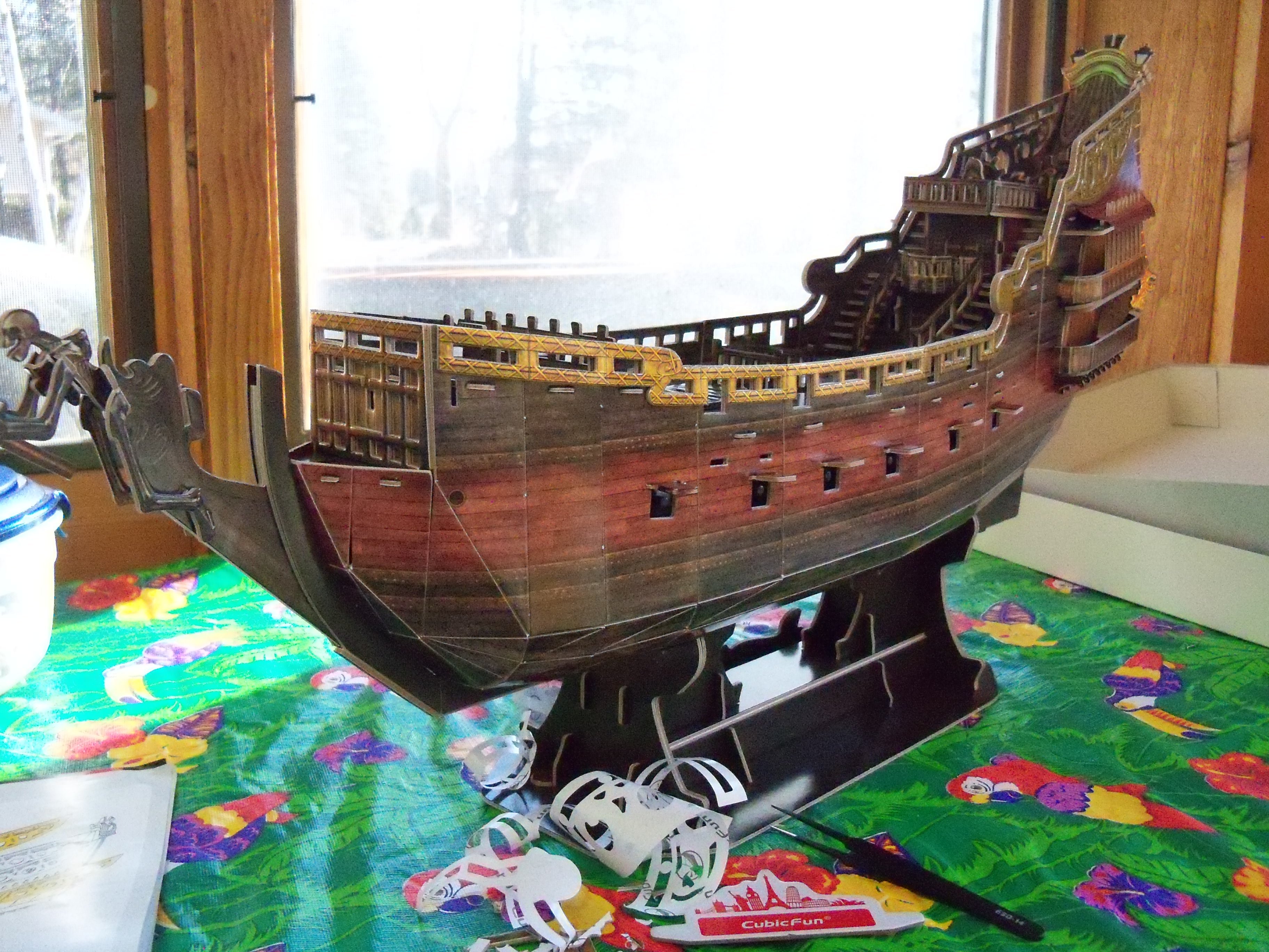
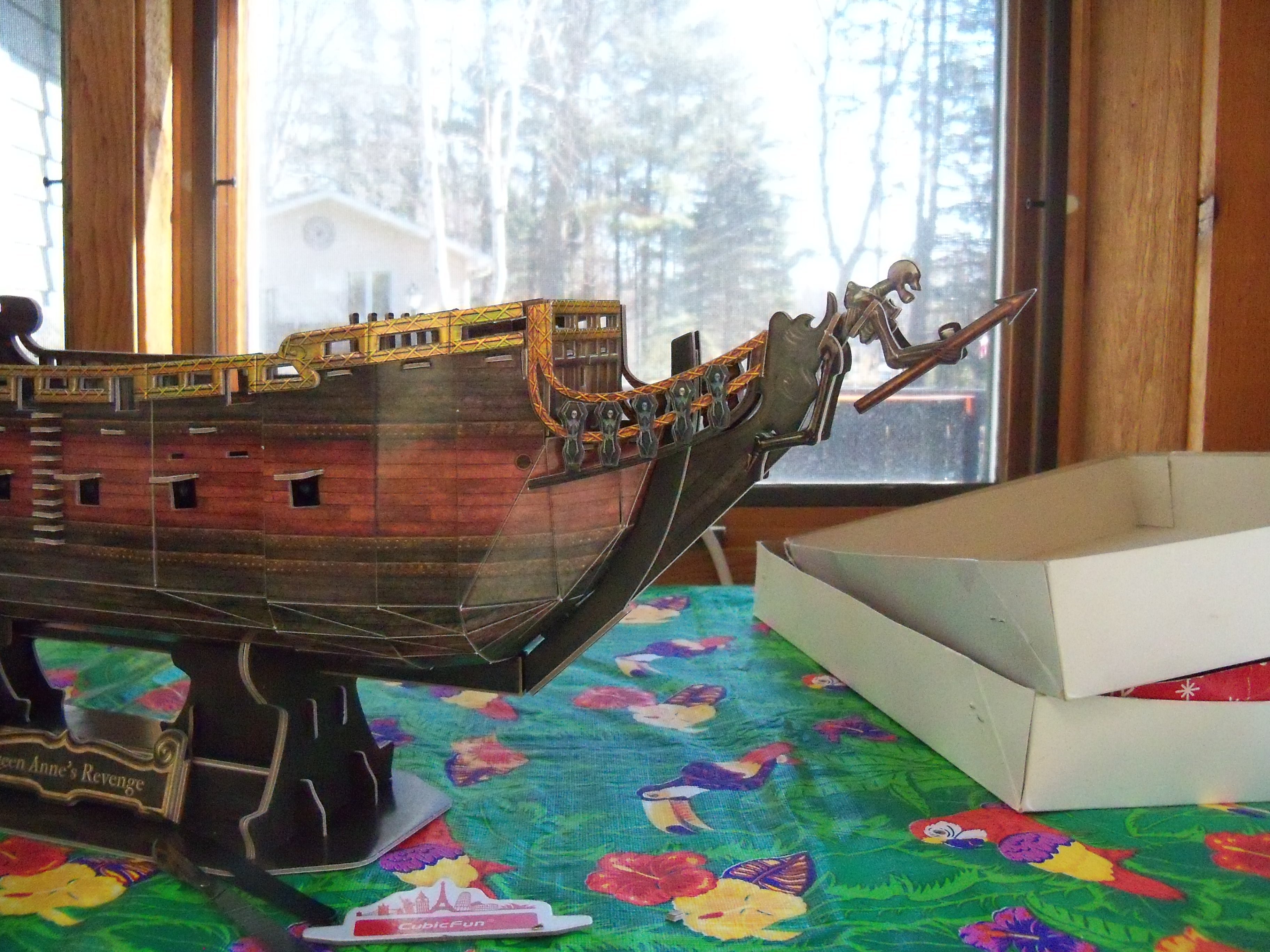
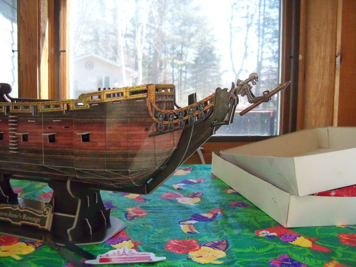
Moving on now to the instructions for step I, as shown below, it was time to tackle some of the trickier parts to apply to the ship. The tape backed gilded finish ornamental railing facing parts T6 & T8 had to be stuck into place at the stern with their top edges even with the top edges of the existing railings. While they had to butt into the transom trim and align with all the openings, they also needed to blend into parts T9 and T10 (to be added next) and cover the canopy cover tabs at the same time. It took me numerous dry fits before working out an approach to doing all of that before removing the tape backing to permanently attach them, but it worked out fairly well. Doing the longer railing sections was done similarly, but the very fact that they were so long, made them difficult to keep lined up for their full length. Try as I might, they would not quite reach all the way to the head-rails. (That had yet to be installed!) I think that it had something to do with the fact that they were single pieces trying to match the numerous jointed hull sections. I think that it was somewhat of an accumulated error. The head-rail assembly, normally a complex arrangement, was greatly simplified in the kit. Part #203 had four gilded finish upper rails and two lower black rails. Continuing with the skeleton motif, there were ten (although the plan only showed eight) taped back number T1 vertical rail parts that were actually stretched out skeletons. I applied them to the rails before actually setting the assembly on the ship, since it was easier to apply pressure to secure them on a solid backing without deforming the rails. The assembly was secured to the ship by slipping the bent middle portion into a slot just behind the figurehead and two additional tabs into corresponding slots on the bow. And yes, that is when the noticeable gap in the joint showed up. While not totally satisfied with the results, I felt it was close enough. (Or as my father was always fond of saying “close enough for government work.)😇 Here are a few photos of this step. Next up is adding the remaining deck fittings and the bowsprit.

- 9 replies
-
- 4
-
-
- Queen Annes Revenge
- CubicFun Toys
- (and 1 more)
-
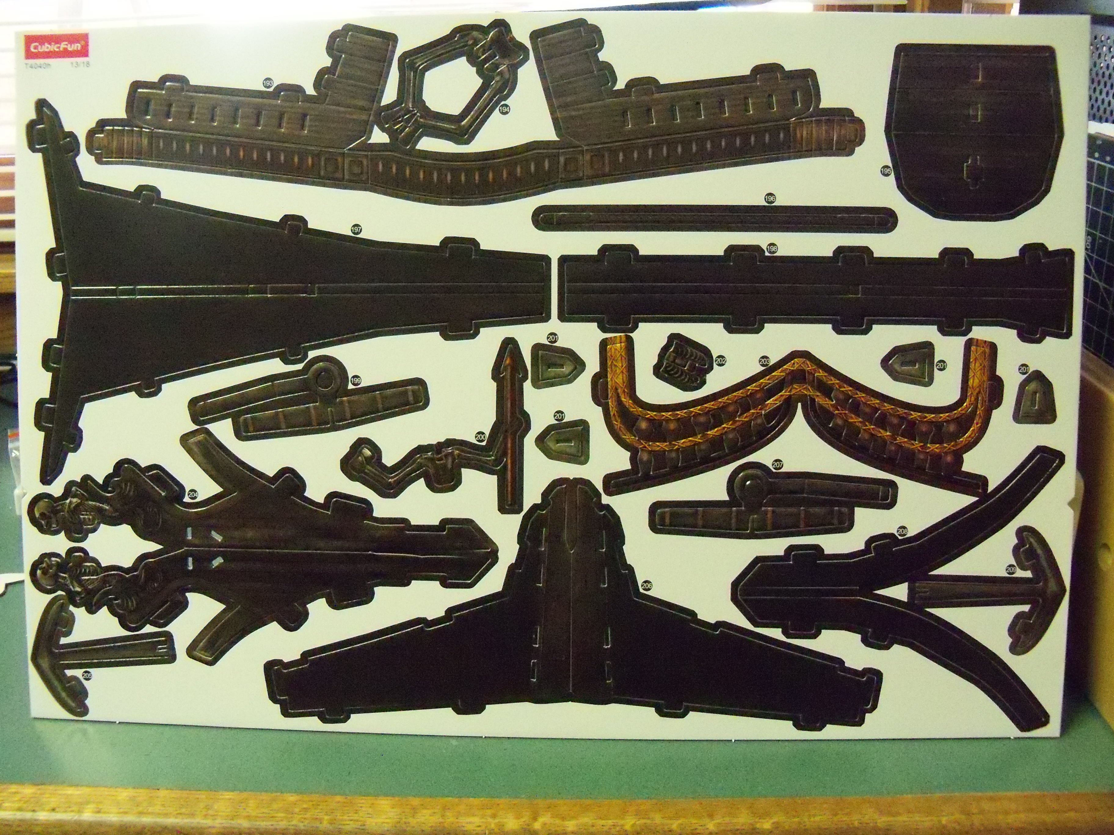
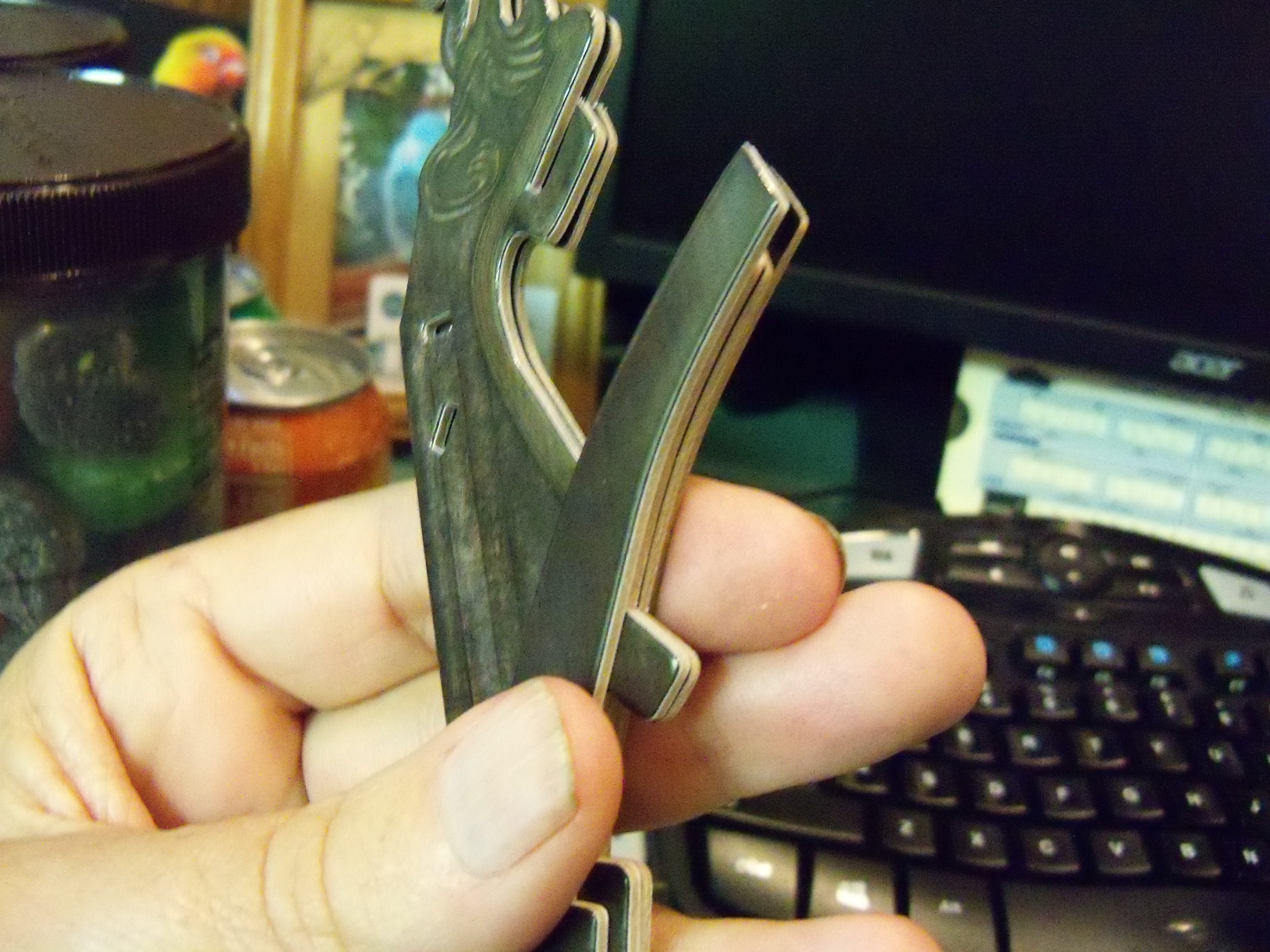
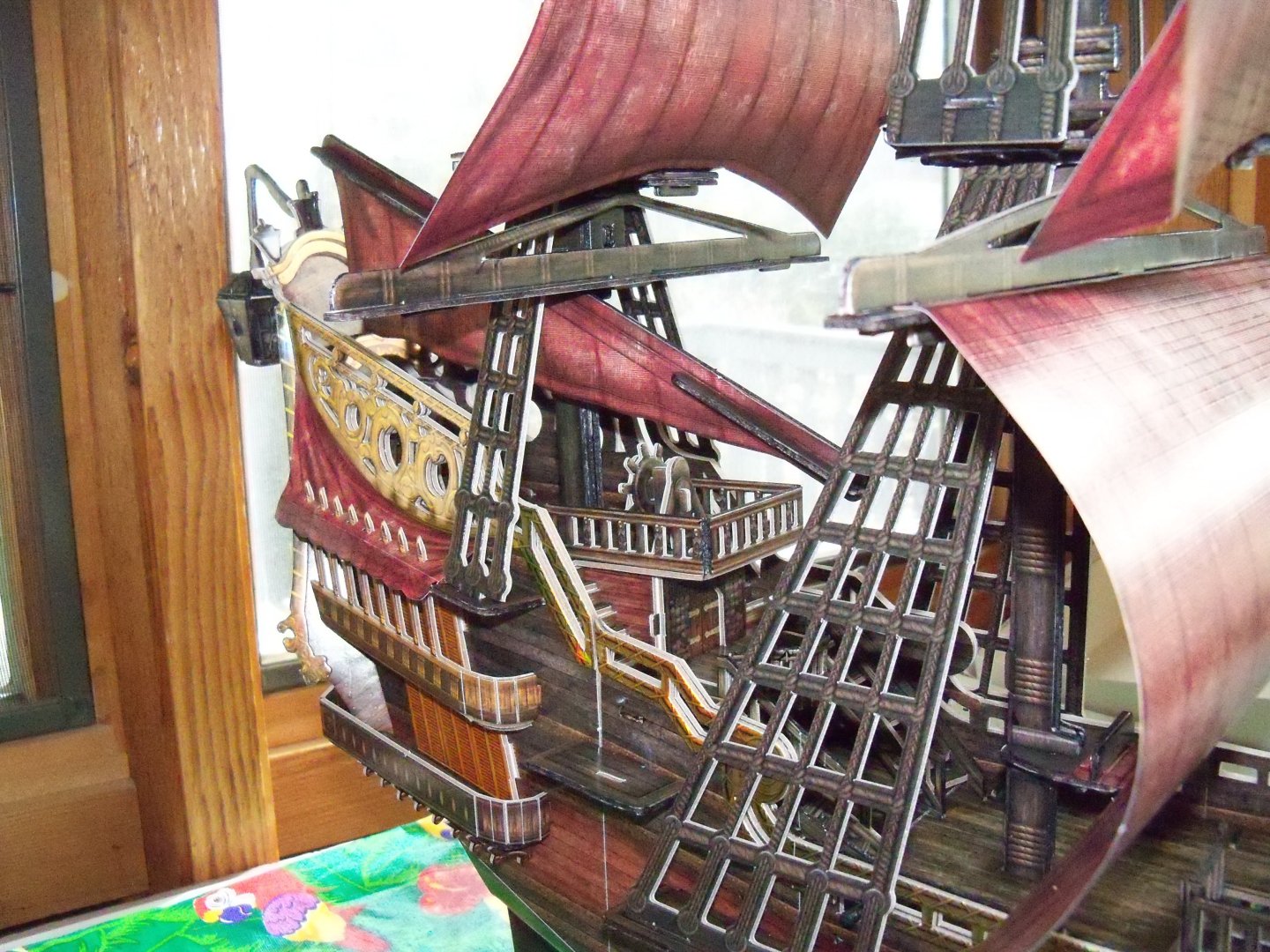
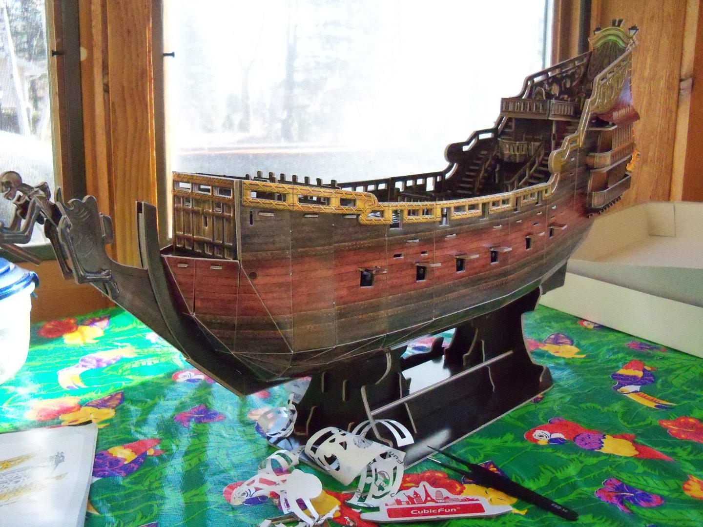
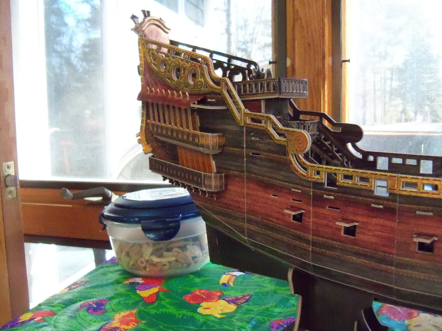
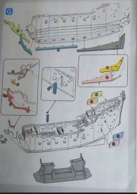
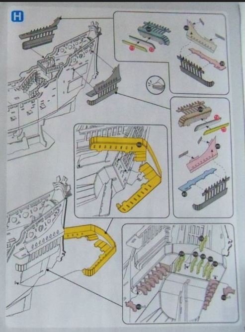
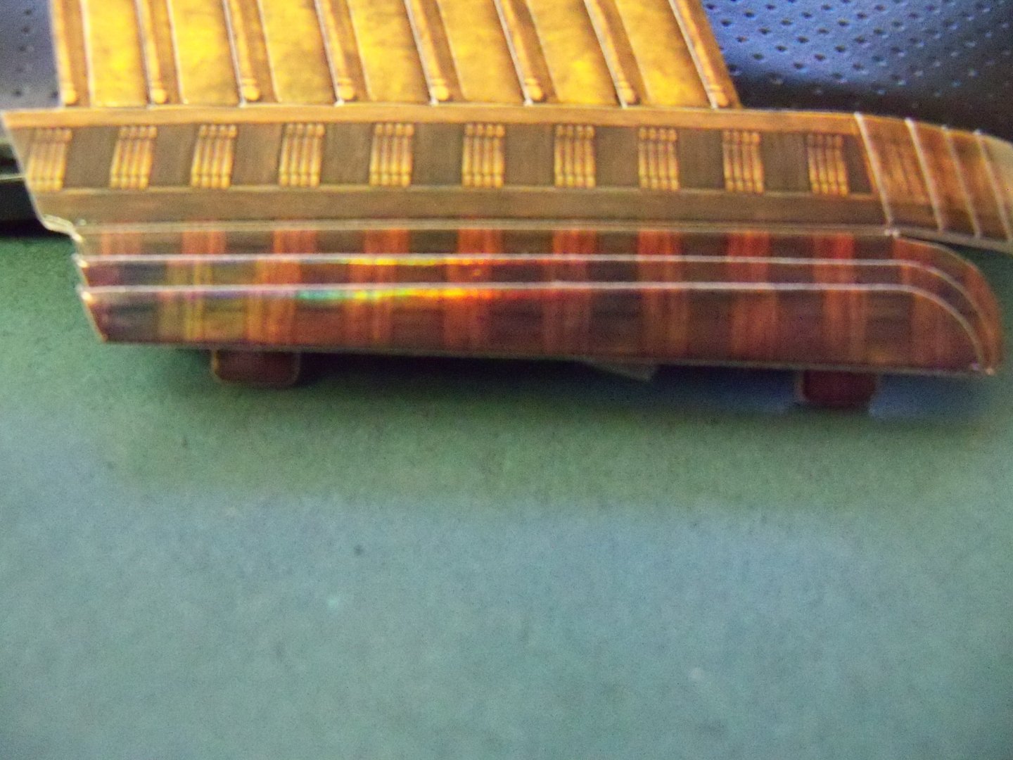
Step G was primarily concerned with the installation of the ships keel, stem, and rudder as shown on the instruction sheet below. Billet 13, shown below, contained the majority of the parts involved with this step. The slots on the bottom of the planking sheets were somewhat unique, as shown below, in that they were made to accept both the long double ply tabs of the false keel and two separate shorter ply tabs of the actual keel that in effect made the keel itself a total of four card ply's thick. I started with the center keel (part #198) which had one end wider than the other where it would join with the stem and a hole to punch out where the ship would seat on the display stand. It also had a pair of bending seams that ran parallel to each other down its center for the length of the part. You can probably make out those seams in the photo of the billet above. This effectively allowed the sides of the part to be spaced enough to accommodate the double thickness of the false keel tabs that were already projecting through the planking sheet, but it also resulted in a somewhat rounded over edge to the keel. The aft portion of the keel (part #197) was somewhat similar in that it had the parallel bending seams and a hole to join to the display stand, but it had two additional slots for the two ply rudder (part #206) which needed to be sandwiched inside of it. After joining those three parts to the ship, it was on to the stem portion of the keel (part #208). This piece was quite intricate, so extra care was needed to get it separated from its billet without deforming the skeleton figurehead. This part was also similar to the previous keel parts, except for the fact that the parallel seam didn’t run the full length of the part, leaving space inside of it for (part #204) which was the remaining part of the stem as shown below. Once the completed stem was installed on the ship, the arms, legs and chest were installed per the included subset illustration. Since the skeleton was in such an exposed position and was so fragile, I reinforced all of his joints with a dab of glue. So here he is now, installed at the bow in all his glory leading the way forward. There were also ten steps for the entry ladder to be added next, followed by four window shutters for the rear cabins. It seemed to me that the ladder and the name plate should have been on the same side of the ship, but the stand can easily be reversed since it wasn’t glued together. Step H, as shown on the instructions below, was tackled next which included four more unlabeled subsets for the upper and lower quarter galleries. I started with the starboard upper gallery part #243, which was actually a combination of the railing and deck. Once again careful removal of the part from its’ billet was essential, but the kit parts were all very precisely cut. One tape backed trim piece (#T2) needed to be attached to the bottom-side of the deck and another tape backed trim piece (#T3) to be attached below that. However, there was no description of how it needed to be aligned and once attached it would be very hard to realign. Looking closely at these three parts below, you can see that apparently there’s a pattern printed on their faces showing deck beams. So I lined up the patterns and the two straight edges which left a somewhat smooth curved transition, which I assume was the intention. The deck now had to be folded under and the front side of the lower railing bent into a curve to match the deck. The roof of the gallery consisted of two parts: a hard surface and a canopy. The hard roof (part #39) was actually a channel for the Mizzen shrouds and its installation was very straightforward. Once the gallery deck tabs and the channel tabs were aligned with their corresponding slots, the assembly was installed. The canopy (part #254) on the other hand, was a bit trickier. This was the first introduction to the printed paper parts. The pointed poles were to protrude through the punched holes in the canopy and a crease was required to bend the lower apron over the beam. The two tabs on the top edge needed a bit of the double sided tape provided with the kit. These tabs were attached to the sides of the rear castle walls where they would be concealed below the gilded rail facing part #T6. This required forming a slight belly in it to to allow the top edge to follow the lower edge of the railing trim. After the completion of the upper starboard side gallery, I repeated the procedure for the port side gallery. So now it was time to move on to the wrap-around lower gallery. This was a very awkward installation, as it was all formed from one part (#193) with numerous complex bends, folds, and tabs to align all at the same time. I over-bent (beyond 90o) all of the required bends ahead of time to make it more flexible. But, if I had to do it over again, I would have glued the tabs in place as I went around, or if I had an extra hand or two, but then you know what they say about ifs, ands, or buts….😁 As it was, I inserted the tab in the end of the railing first and then two of the side deck tabs before manhandling the four rear deck tabs which arched to follow the arch of the bottom of the railing. Now, while still holding all of that in place, I set the side deck tabs and the final tab at the end of the railing. I think the hardest part was trying to insert the tabs where they went around the corners. The final part of this step was to install the 23 deck support angle brackets. Keeping the arched rear deck aligned with the bottom edge of the railing was one thing that I was never really happy with, but it was over and done with so I just let it go since there was really no way to clamp it and using CA wasn’t possible either. Here are a few photos from step H. At this point, I still hadn't noticed my error with the transom, but more on that later. To be continued.


- 9 replies
-
- 4
-
-
- Queen Annes Revenge
- CubicFun Toys
- (and 1 more)
-
That's definitely a mass of rigging. Looks like any pirate crew would have had their hands full. My card rendition really skimped on the rigging.
-
That's one down, only fifteen more to go?
-
After going through all of that Ron, I'm assuming that you won't be covering your woodwork up with a canvas mast collar coat.
-
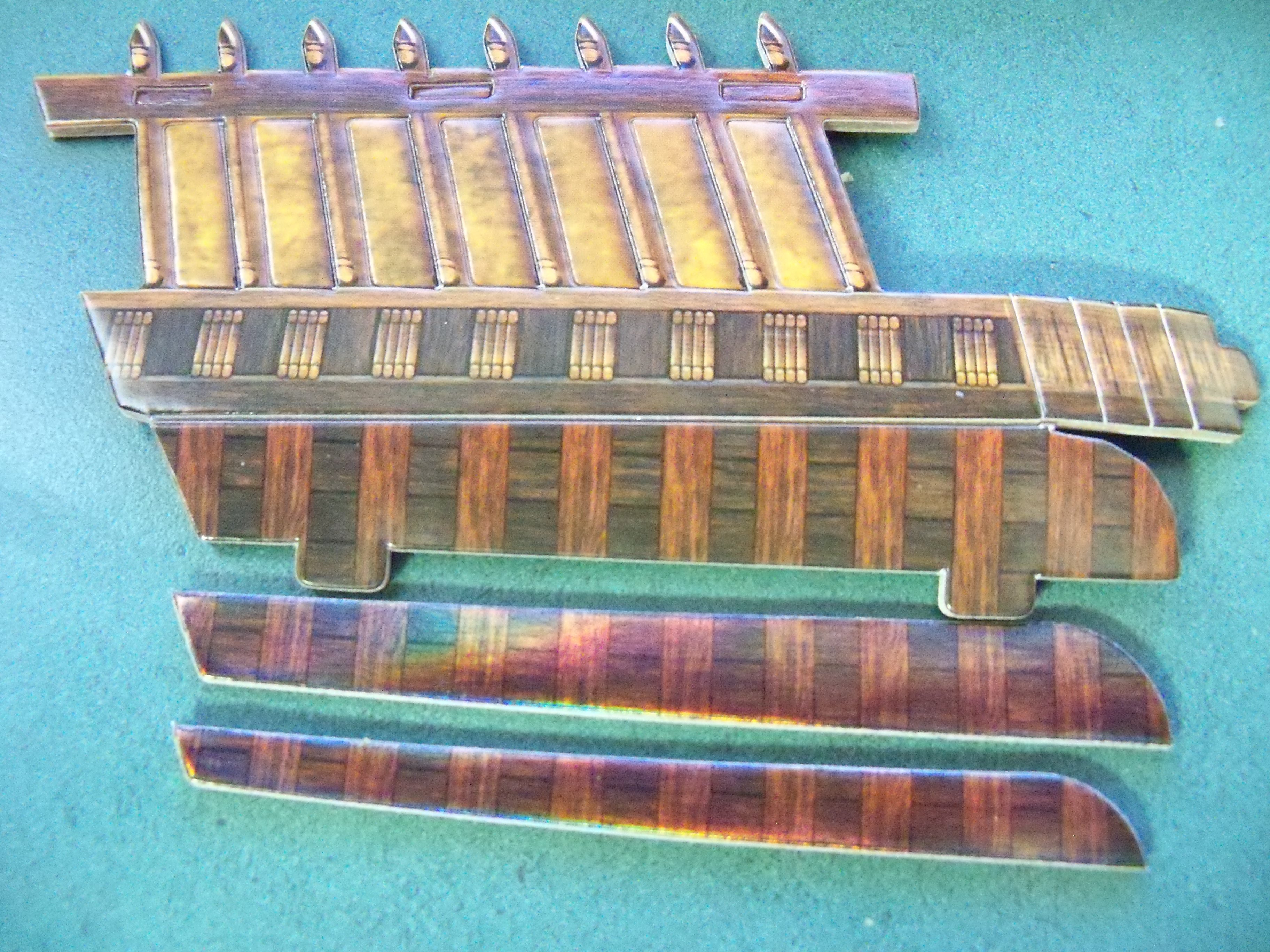
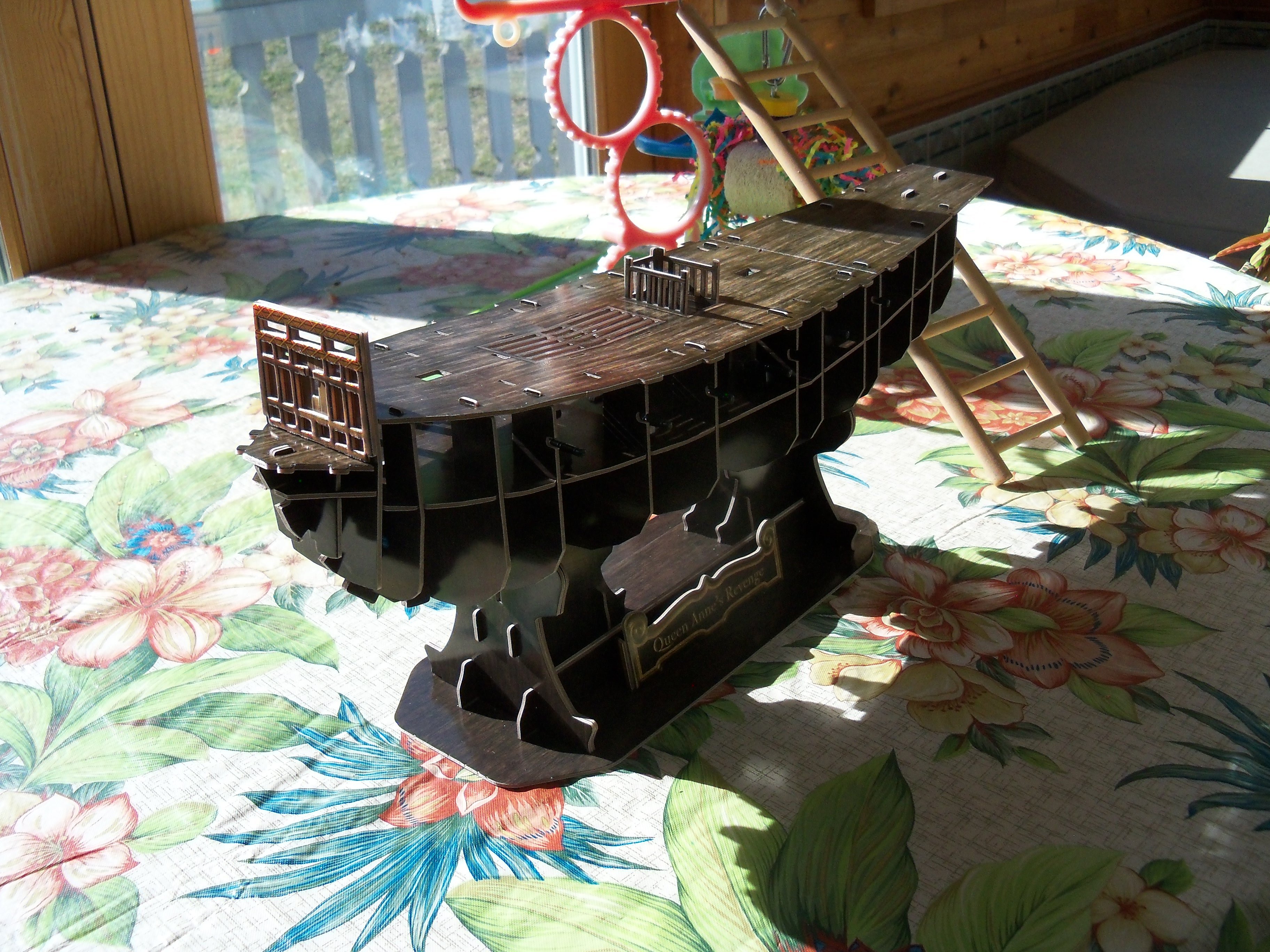
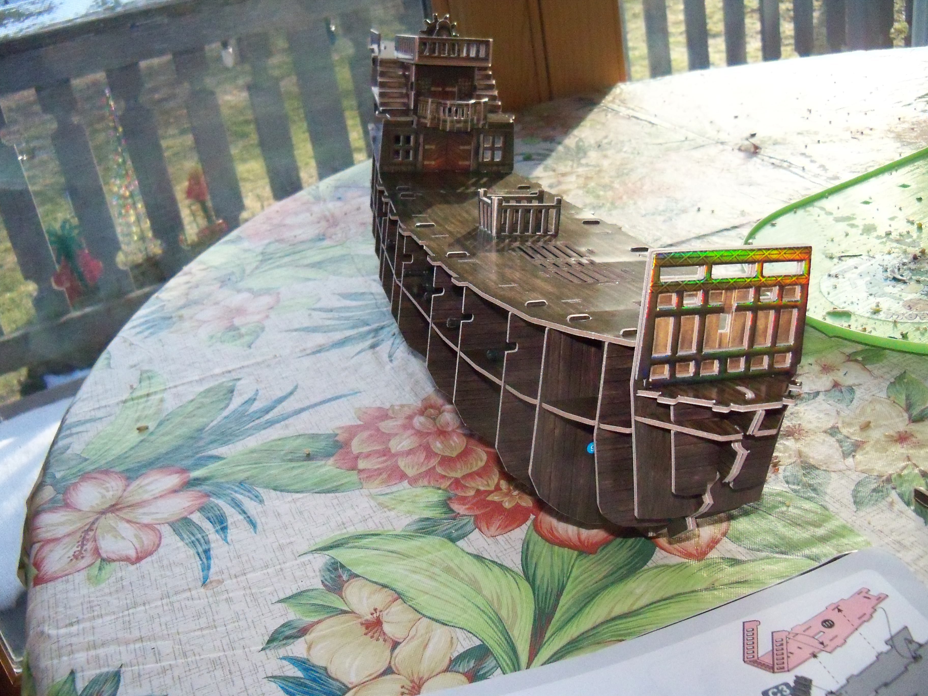
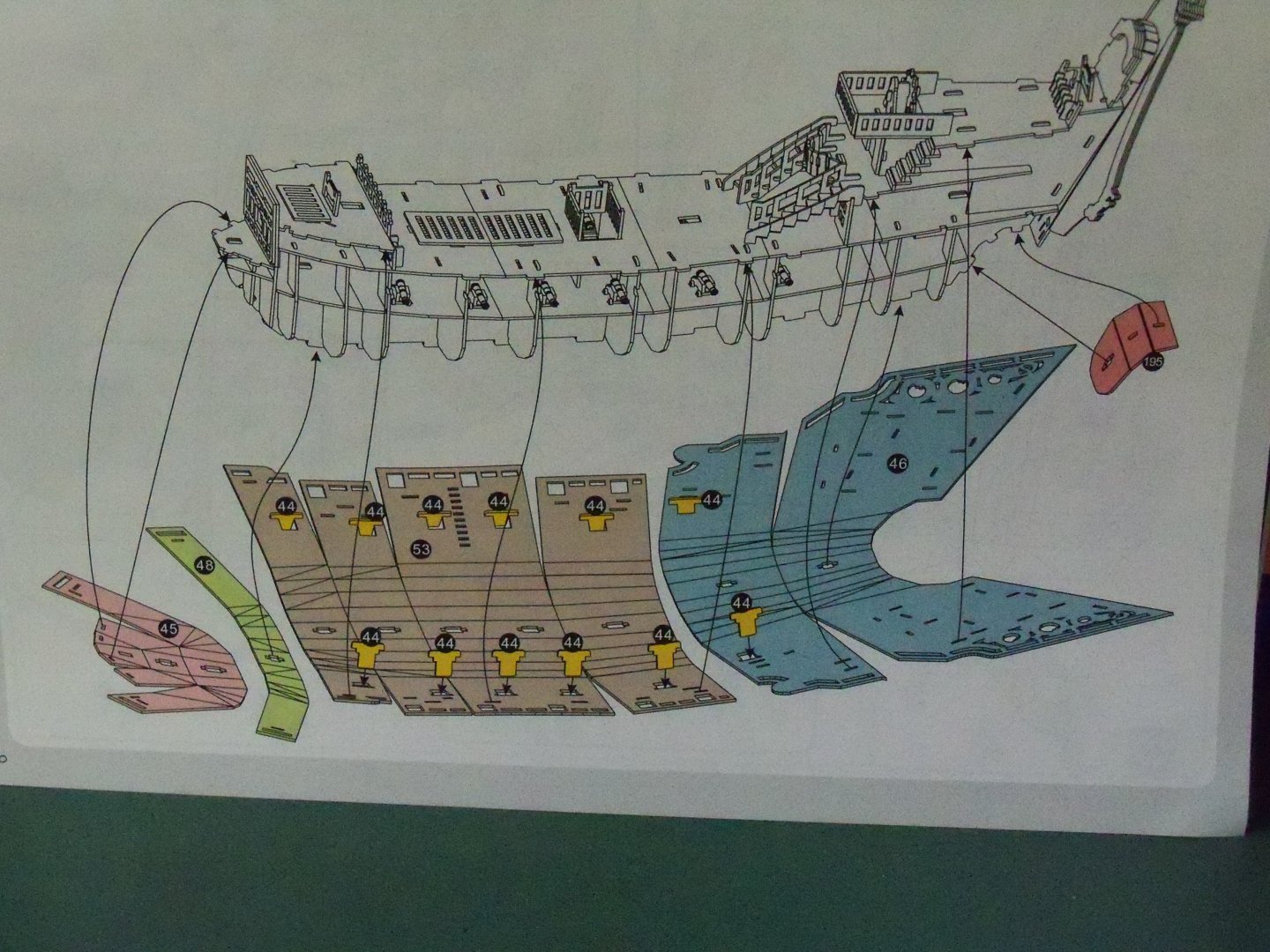
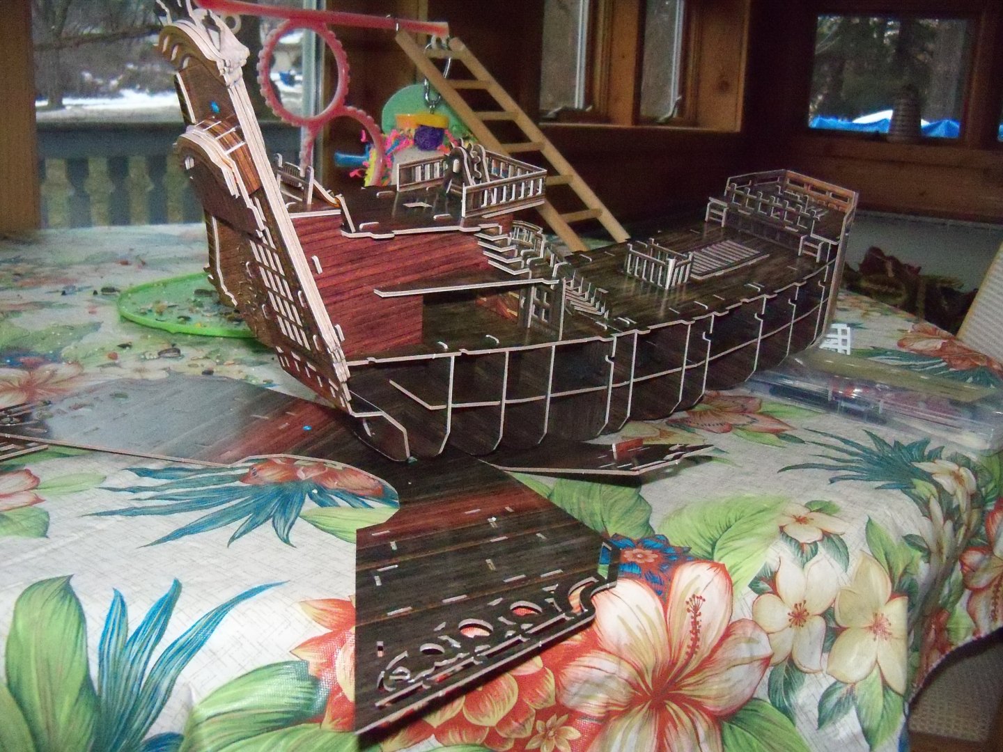
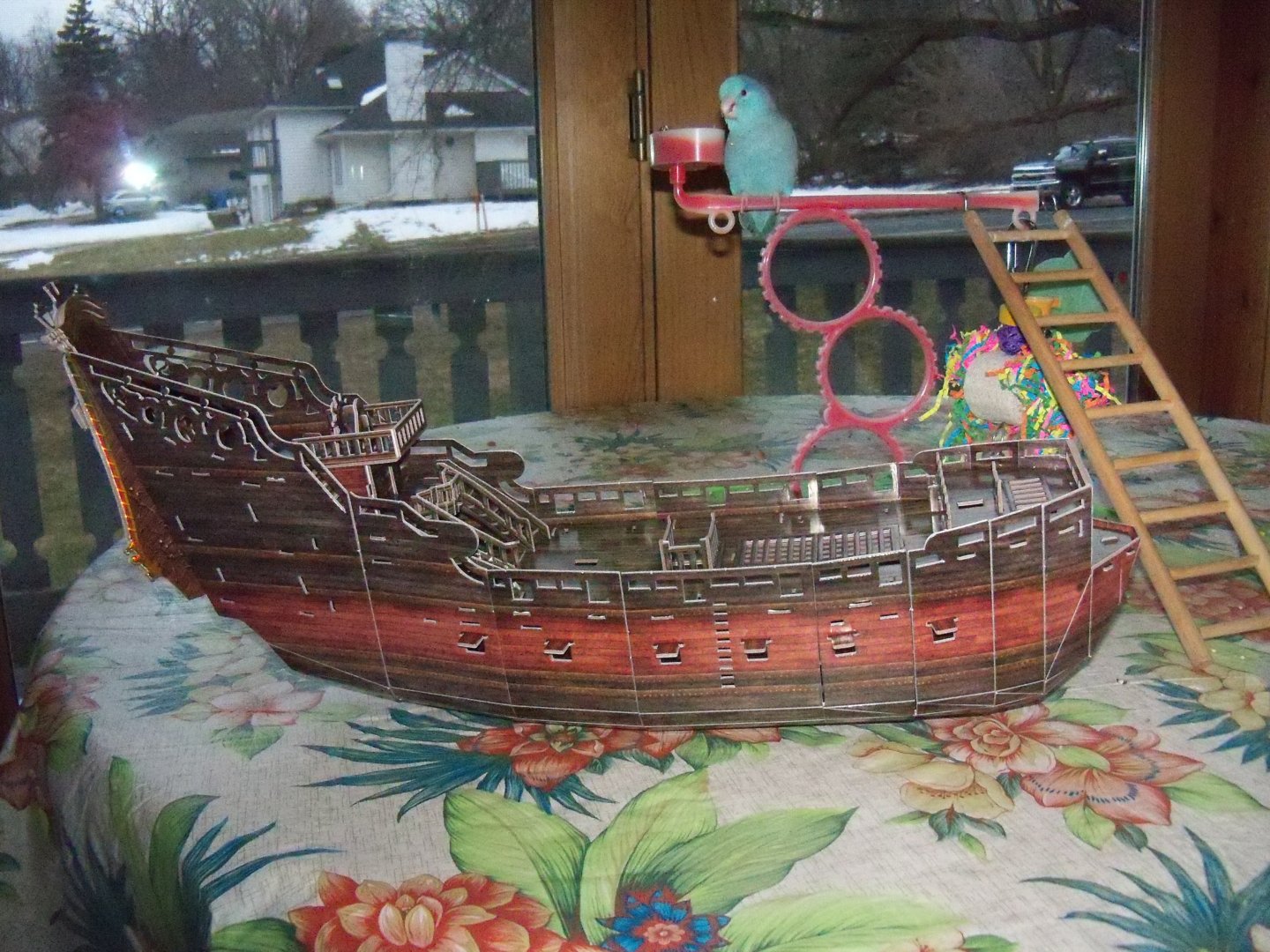
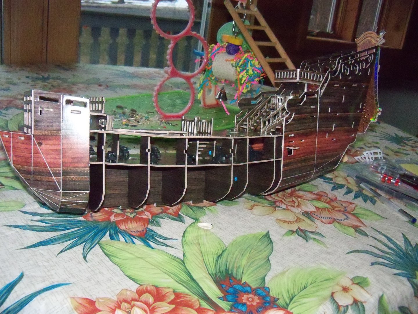
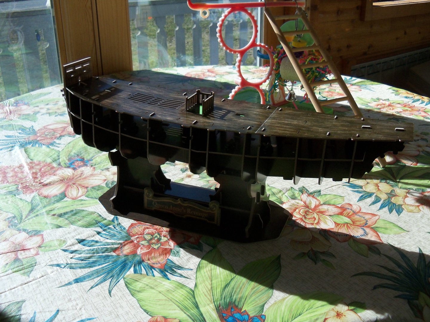
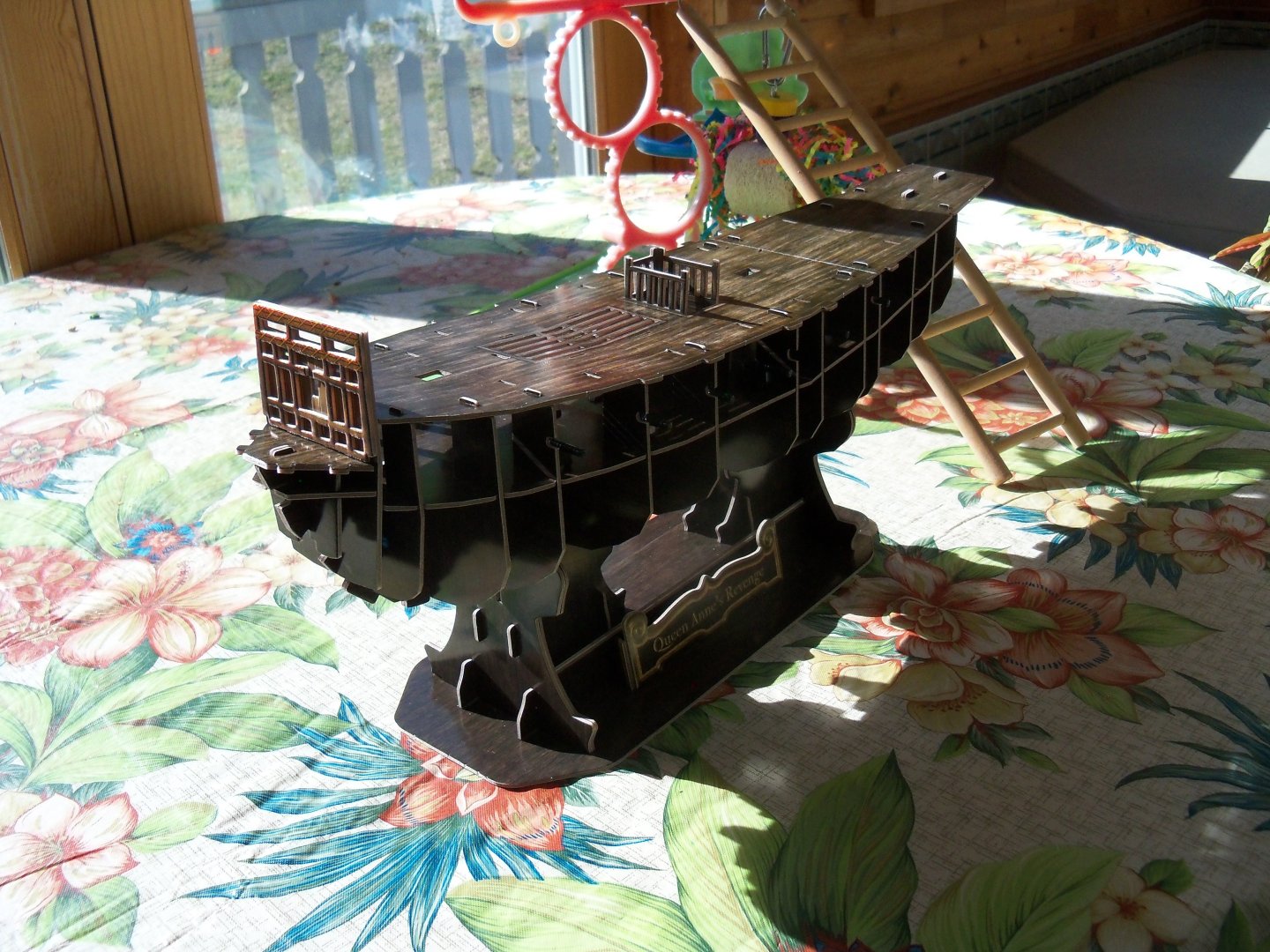
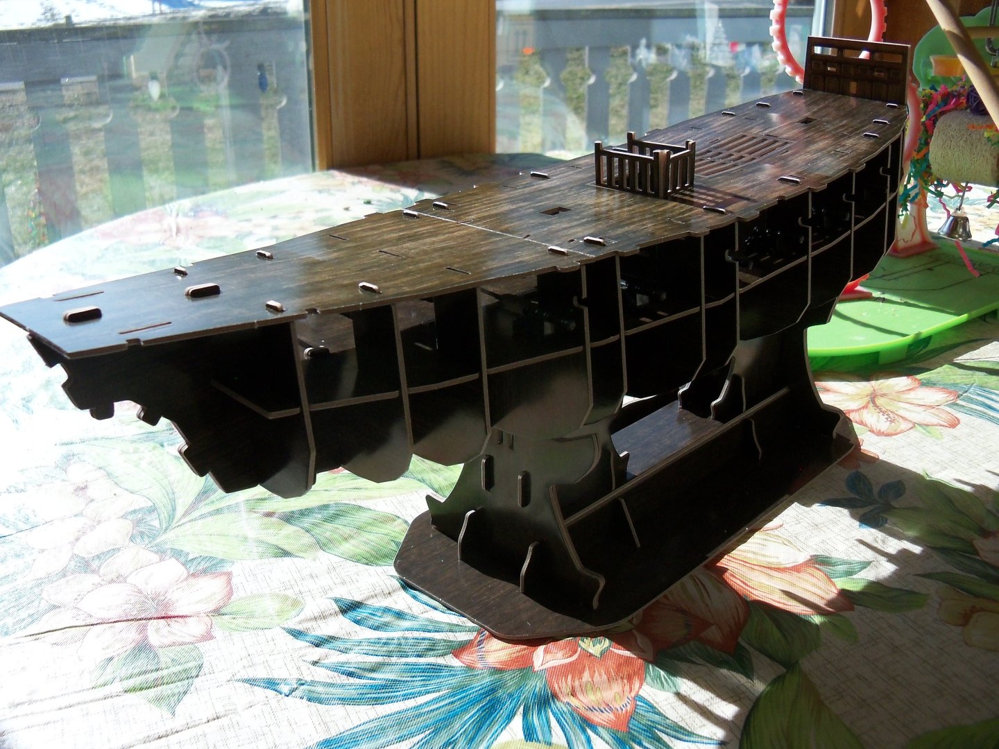
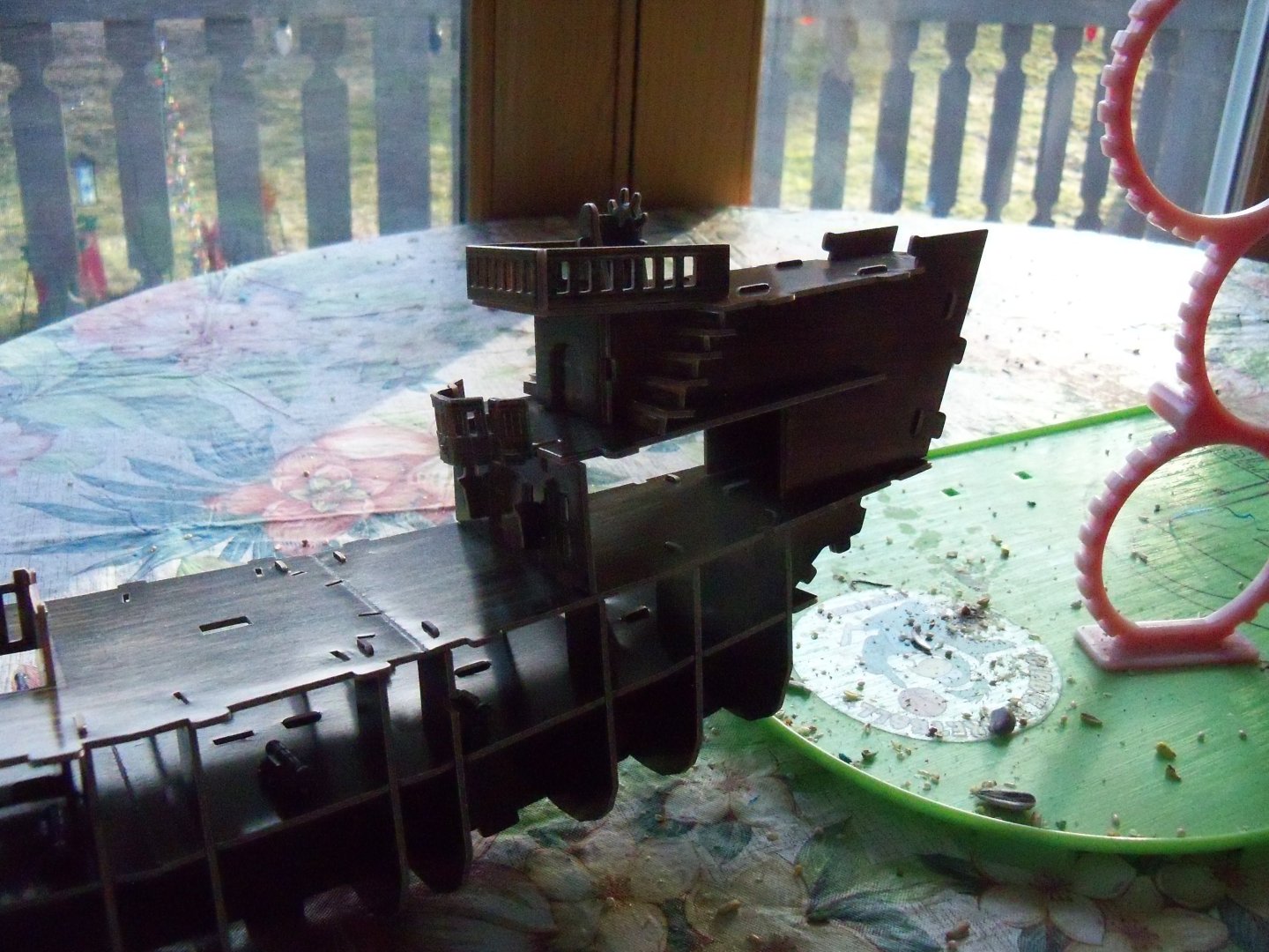
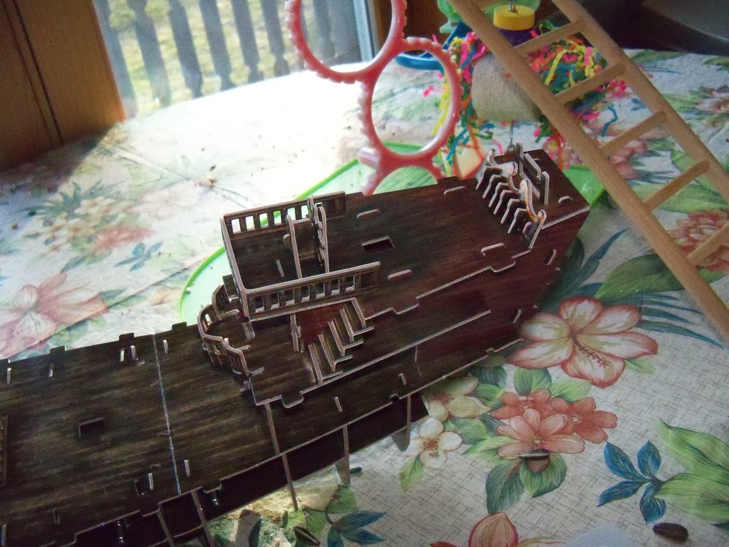
So now that the supporting framework was completed, it was time to plank the hull. Not being accustomed to building a plank on bulkhead model before, it was at this point that I realized that, although this ship was simply a ribbed construction of card, it was a very solid structure and it was already easily recognizable as an actual ship. While the method being used here is not your typical planking technique employed on wood or even card models, it was definitely quicker. Here is the instruction sheet below for step F. I began oddly enough, by installing the ships counter part #195 despite all the other parts being numbered in the 40’s and 50’s. I’m assuming this was due to the fact that there just wasn’t enough room left on the number 5 or 6 billets with the rest of the planking parts so they stuck it on billet 13 where there was. Then all of the gun port lids were inserted from the insides of planking parts 46 and 53, since it obviously would have been a bit difficult to do so after the planking sheets were in place. The the two projecting keel tabs on the aft portion of the ship were stuck through the corresponding slots of planking sheet number 46 as shown below, while I contemplated exactly how to handle the ship while lining up the four slots with the four tabs on opposite sides of the poop deck and the two on the deck below at the same time without knocking the two stairs off. Having successfully installed that part without any mishap, I easily attached the two bow sections followed by the remaining central section as shown below, with my supervisor looking on. This completed step F.
- 9 replies
-
- 3
-
-
- Queen Annes Revenge
- CubicFun Toys
- (and 1 more)
-
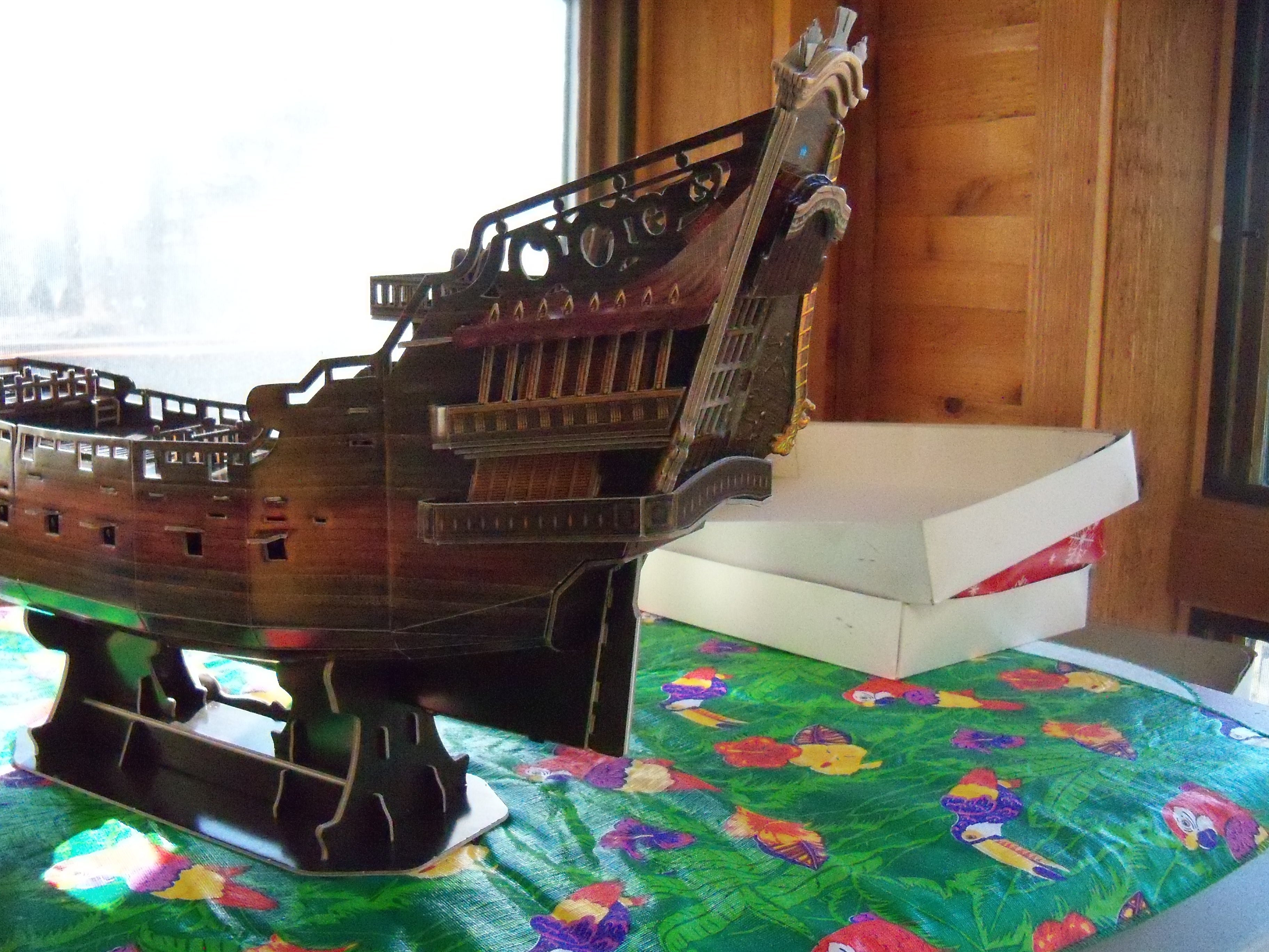
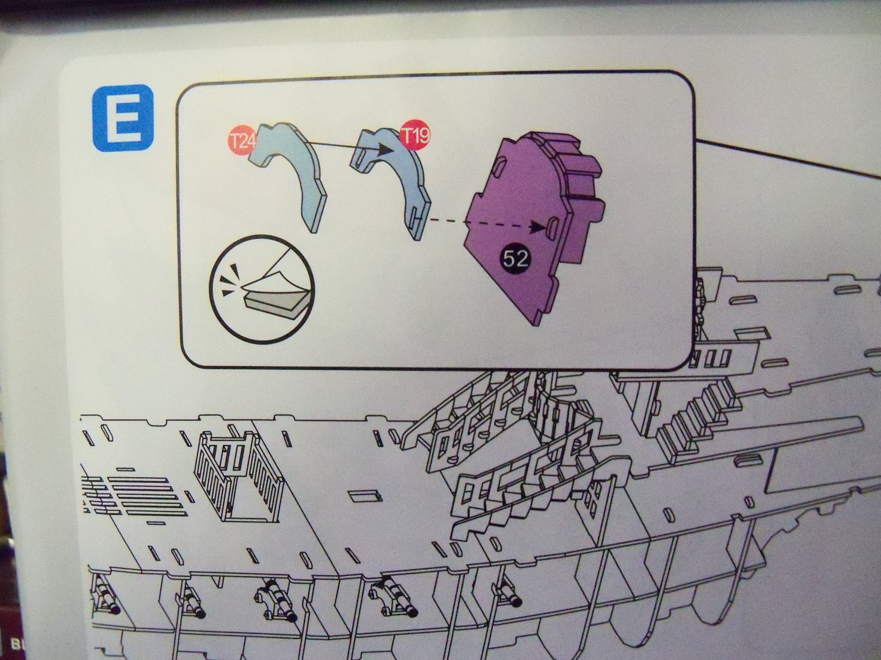
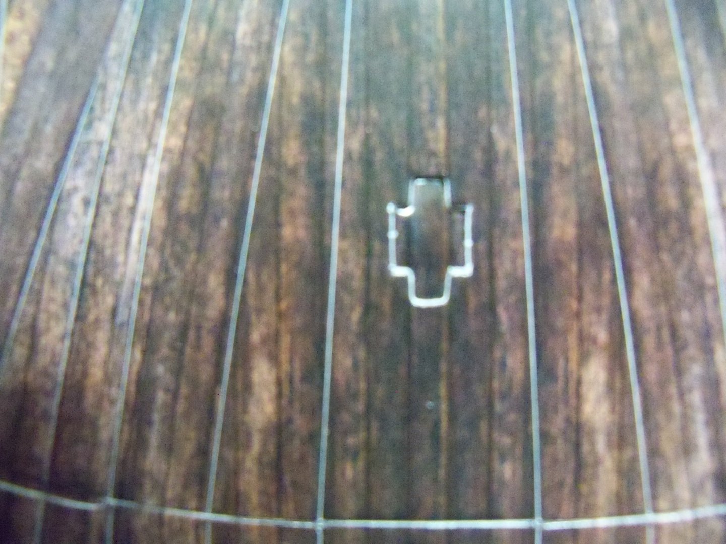
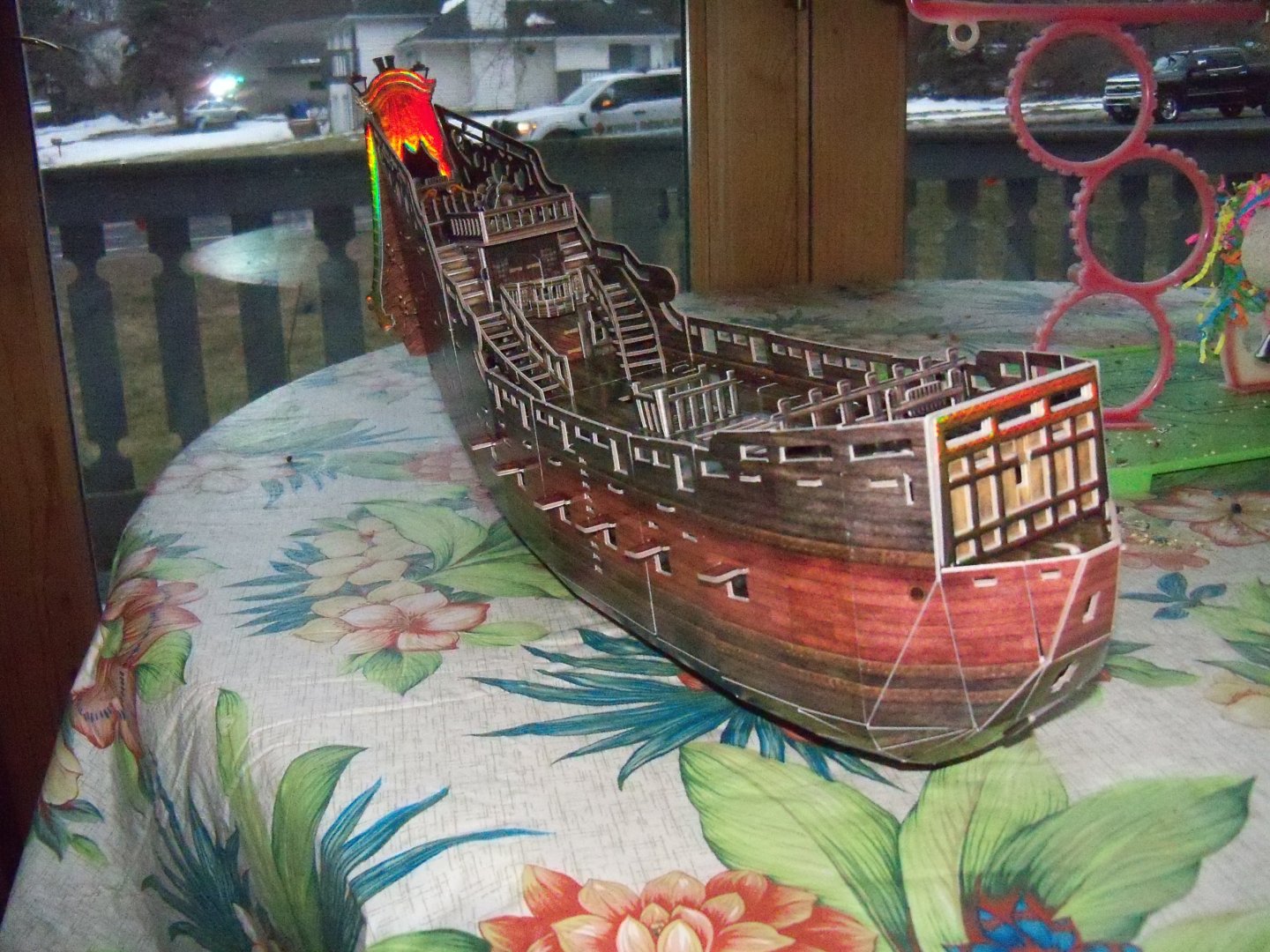
Step E began with an unnamed subset that showed part #52 that first needed the top portion folded over, leaving the number printed on the hidden backside. The top portion was bent over and formed into a curved roof top with two tabs stuck through it that would then project into the gilded trim part #T19. Part #T24 is then added to cover T19 and complete the trim subset as shown below. Continuation of the illustration of step E as shown here. The Mylar part #T4040, representing the stain glass in the transom, needed four strips of the double faced tape applied to its edges. Once again, the alignment was critical in its placement on transom part #116 so as not to cover up the slot openings. Next, all of the gilded trim pieces T11 through T23 and the unnamed subset were added to the transom. This was followed with another unnamed subset of the forecastle below which included the deck, railing, two ladders and another fife rail that is stuck through the deck from below. The step was concluded with the application of the top cross bars of the deck gratings on decks. Here is the ship at this point. At this point in the construction I still hadn’t noticed that I had installed the first subset and the gilded transom trim on the WRONG side of the transom! More on that later.

- 9 replies
-
- 4
-
-
- Queen Annes Revenge
- CubicFun Toys
- (and 1 more)
-
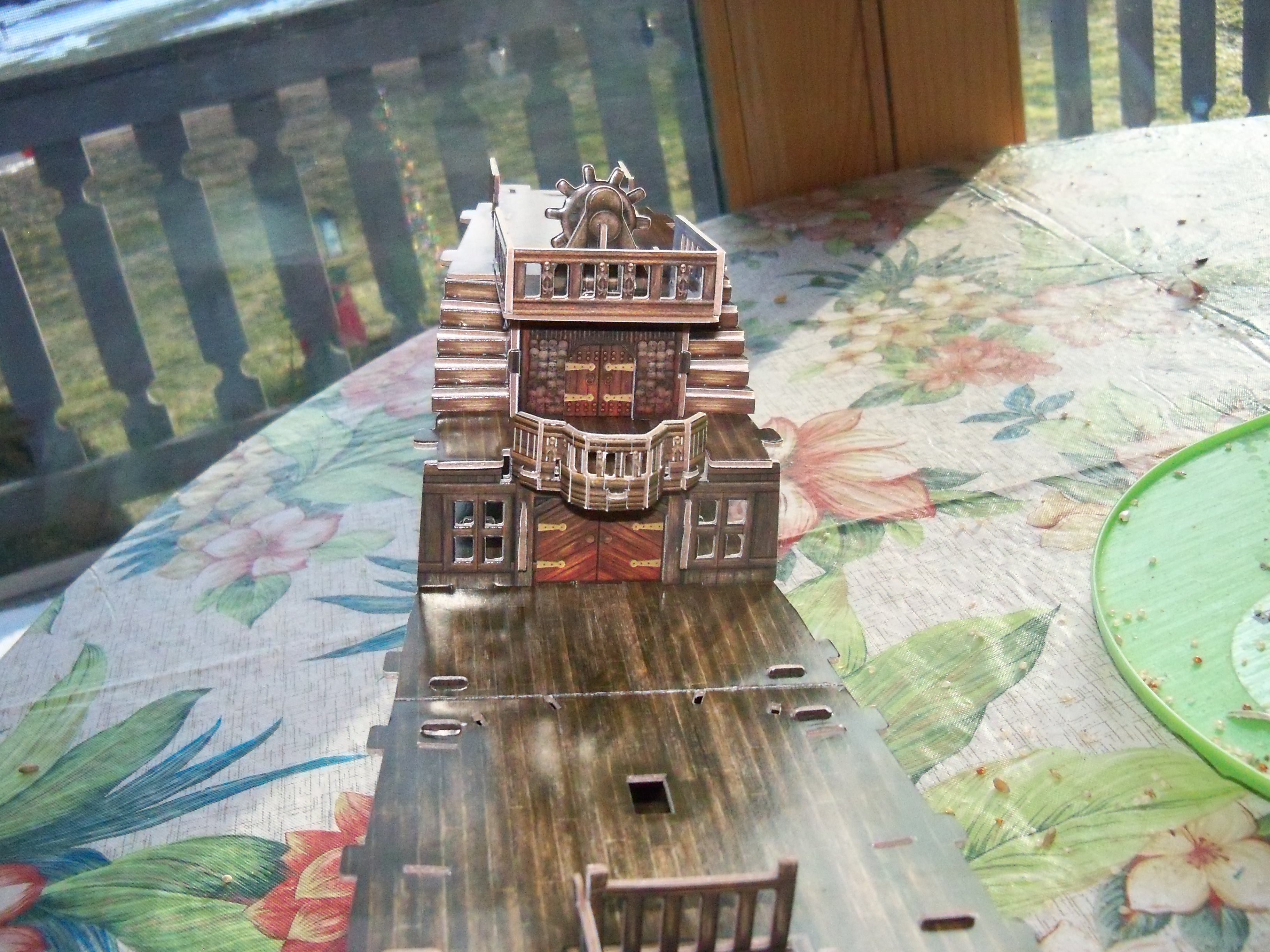
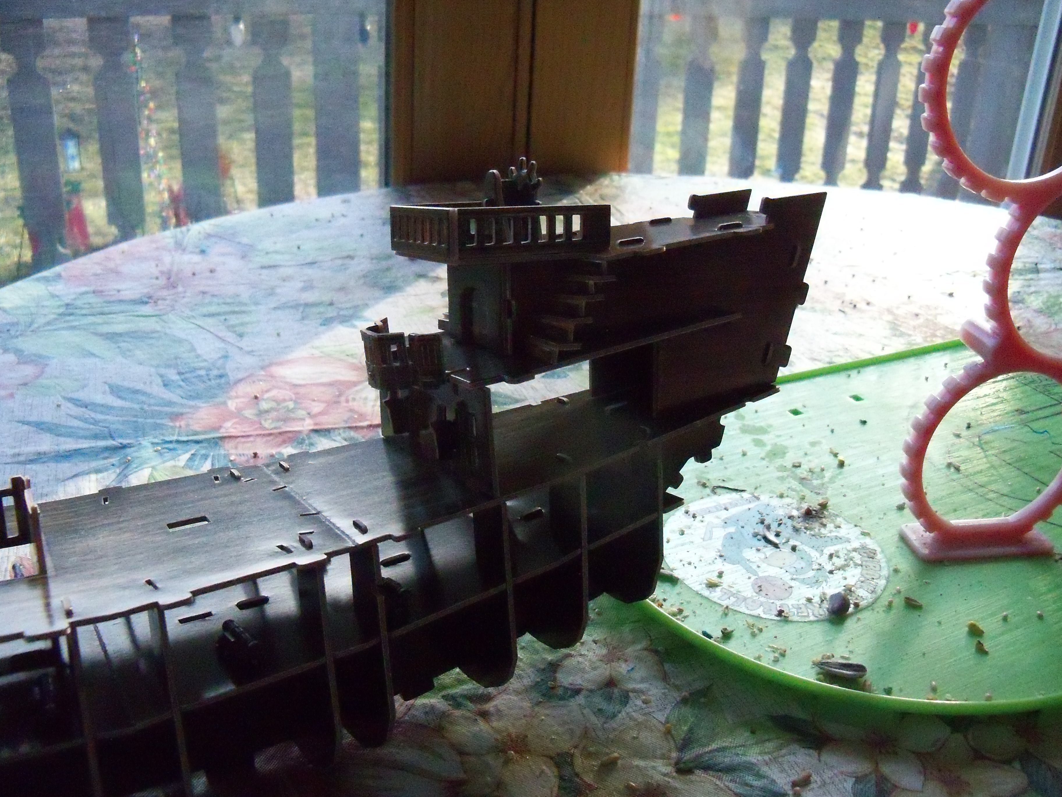
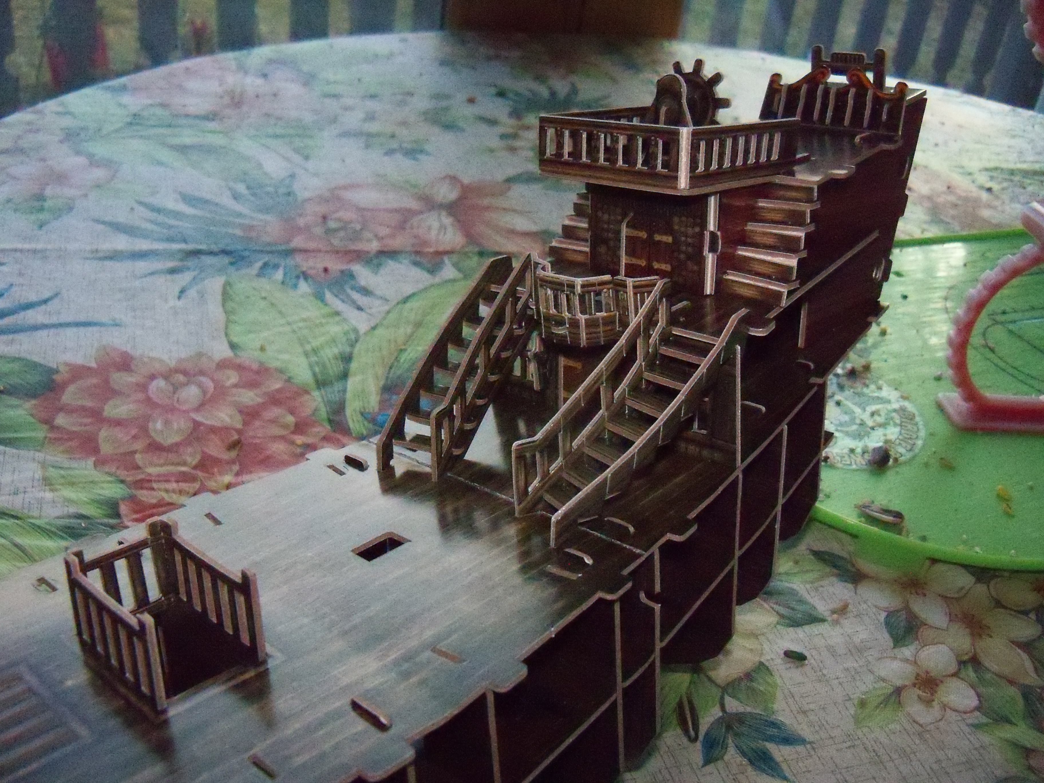
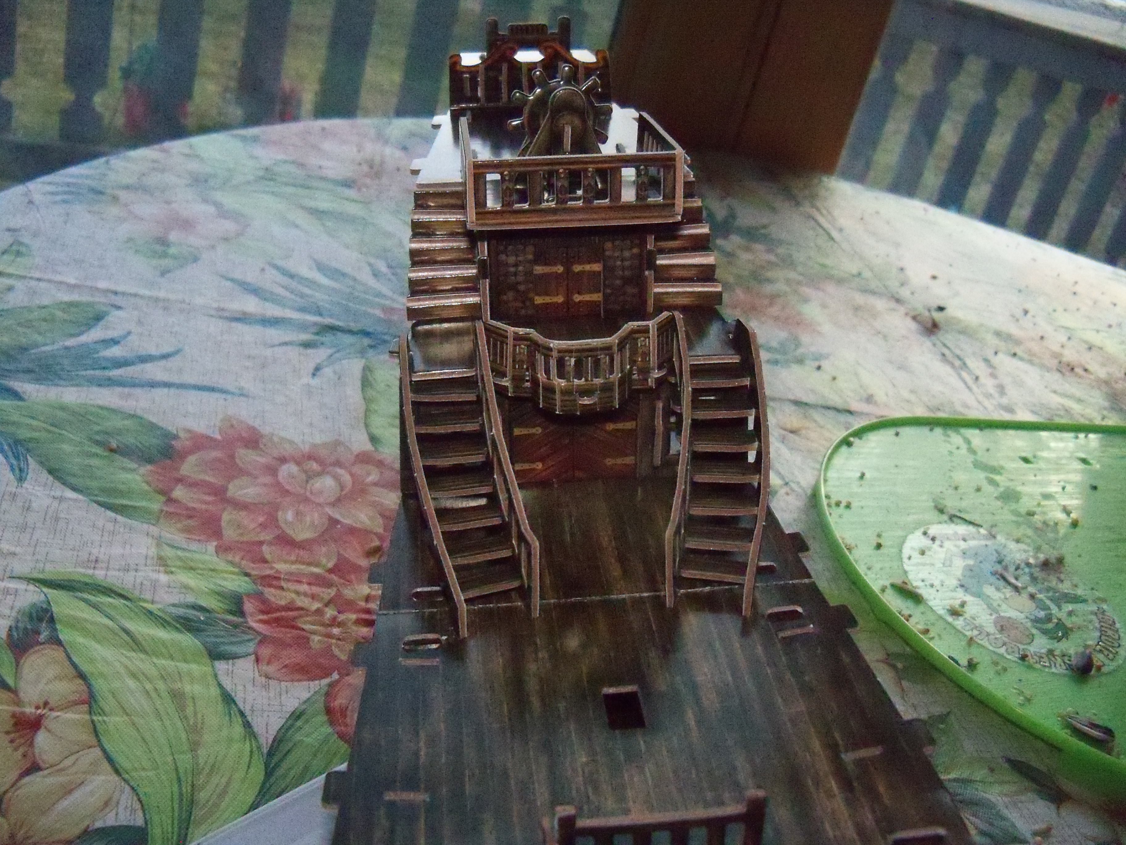
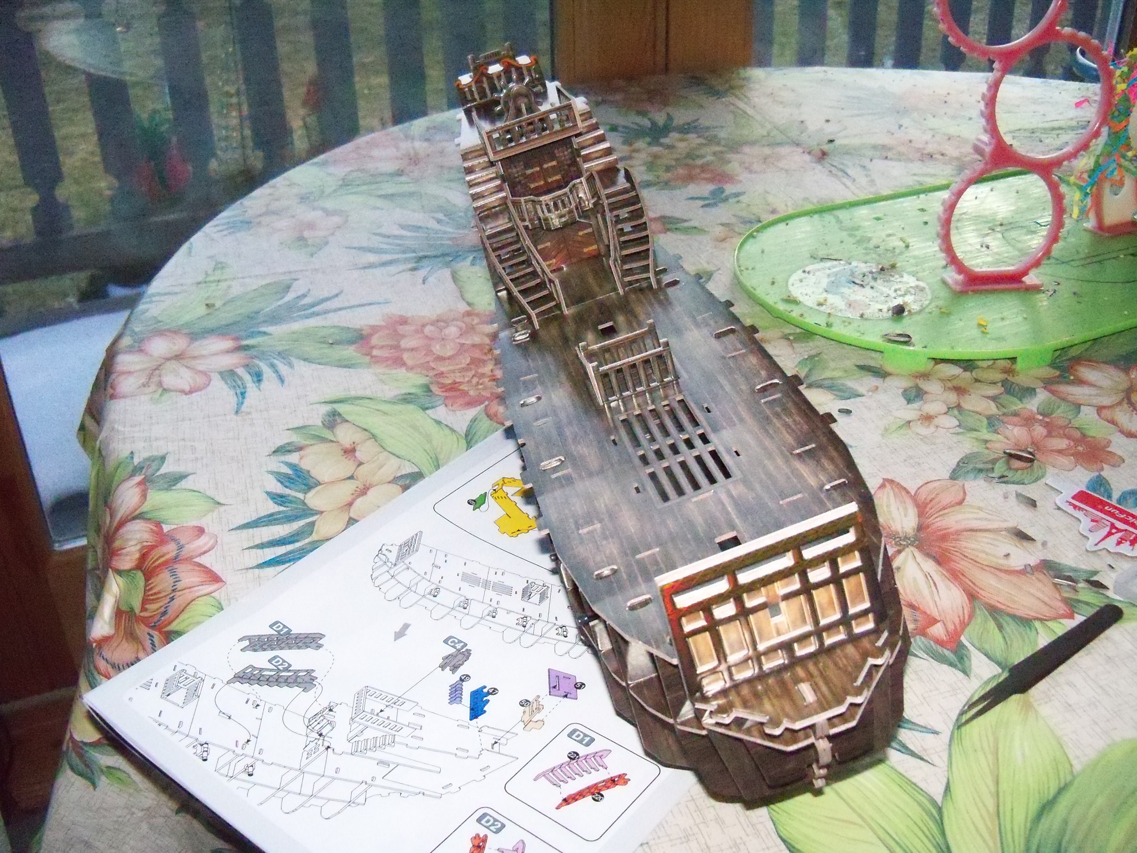
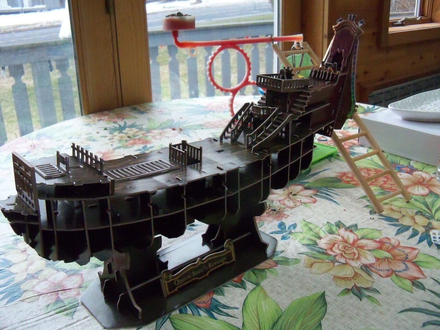
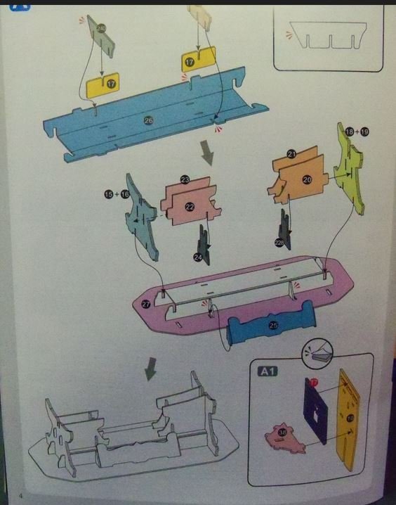
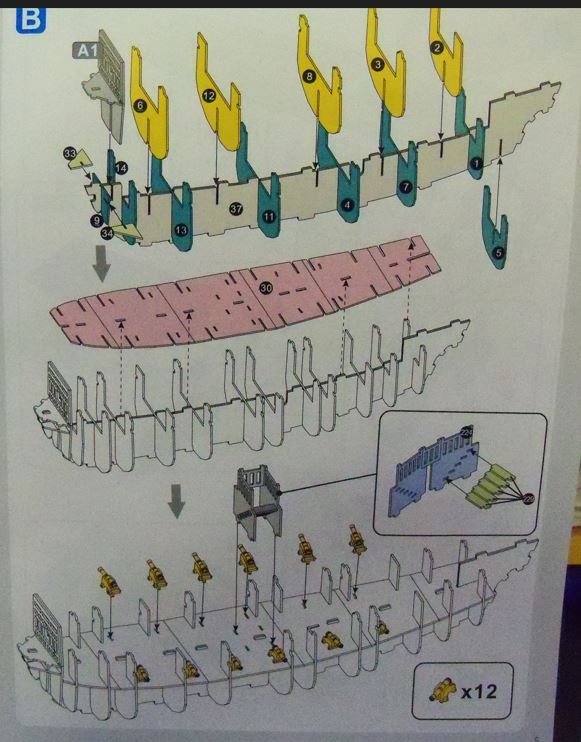
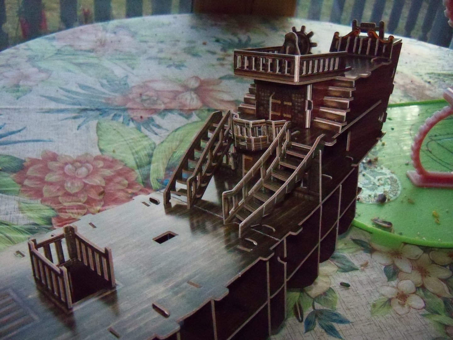
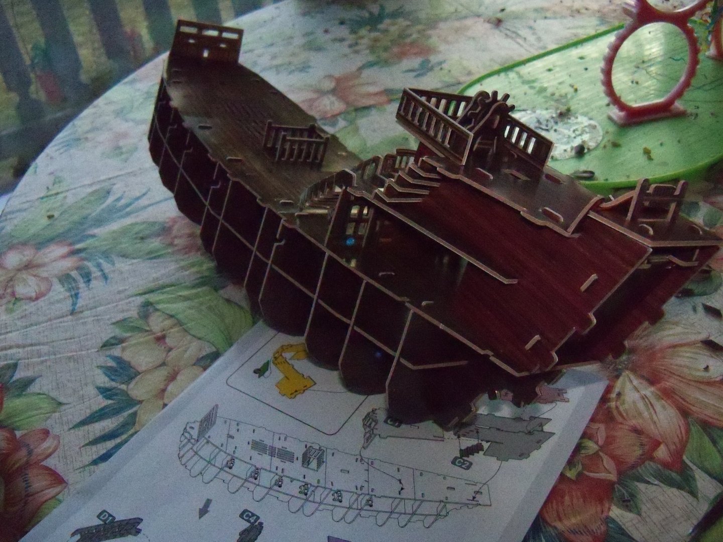
The actual assembly guide started simply enough with step A for the support stand. The part numbering system however, didn’t seem to follow any particular order. Step A, as shown below, started with part number 240 joined to part number 17 which was from an entirely different billet. So I had to do a lot of searching for the correct parts for each step. At least the instructions were well illustrated with contrasting colors showing the parts involved in each step, and the finished assembly shown in white. They included exploded views of subset steps like A1 shown above. Certain parts with a gilded finish were called out with a T added to it. For instance, Part T7 in step A1 above was the first use of one of those designations. The backside of these gilded parts are all covered with paper that needs to be peeled off to expose the pre-applied adhesive underneath. Needless to say, careful alignment is required to allow the exposed edges to blend in with the piece below, because they can't be shifted at all once they are in place. Wherever these parts are employed, this symbol is nearby. As the instructions continued on to step B, the diagram for the assembly of the frames on the keel. The previous A1 subset shown in gray, was brought forward and its new placement was shown below. Just below that diagram, the lower deck part is shown in pink and shows its alignment below that with the framed up keel in white. The first instance of folding a part came up now and was shown as an unlabeled subset. Careful bending was required for this interior stair assembly, because the core of the part could easily separate from the vinyl facing. Lastly, the placement on the deck of the stairs and twelve of the cast black plastic canons was shown to complete step B. Here are a few photos of the state of construction at this point. Step C followed with the alignment of the main deck on the previous frame and several subsets, including the main cabin entrance wall, the next deck above that with its pair of stairs, the curved balcony railing, and the ships wheel. Here is the ship below with the subsets from step C added to the ship and a portion of step D. Step D was actually more of a continuation of C than a separate step. The subset C1 was brought forward and combined with the upper cabin walls and attached to the main deck. The upper cabin walls, the Poop deck above that with its railing, a fife rail that passed through an additional upper rear deck, and various other fittings to go with it were all assembled and added. Step D continued with a pair of curved stairs with subsets D1 and D2. Those stairs were quite a handful themselves, between bending in the curve, inserting the seven treads, and anchoring the ends to the two decks without twisting them out of shape. They are shown below after their installation and the status of the build at the completion of step D. To be continued.


- 9 replies
-
- 4
-
-
- Queen Annes Revenge
- CubicFun Toys
- (and 1 more)
-
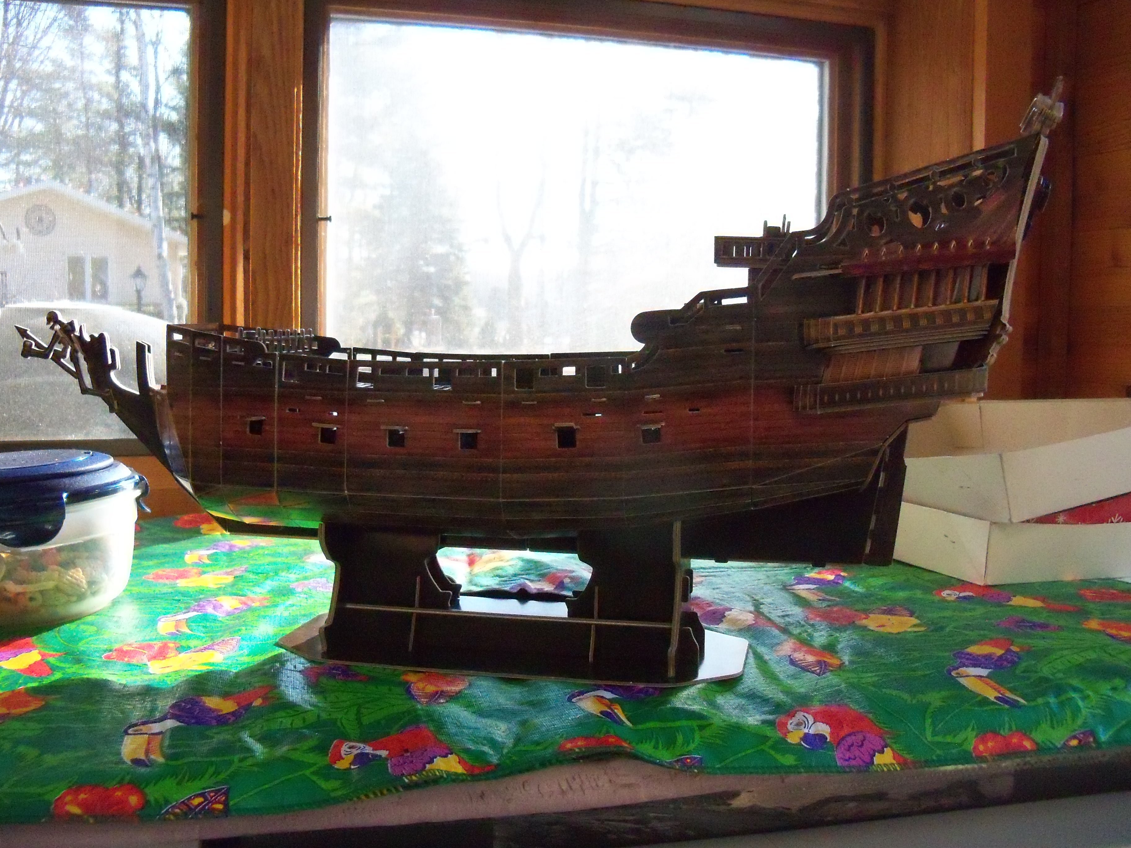
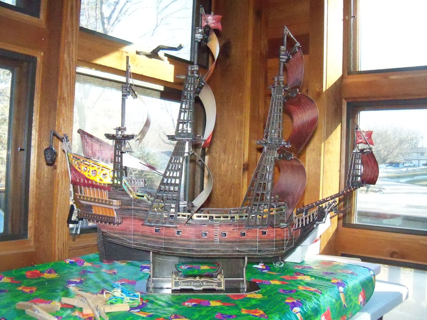
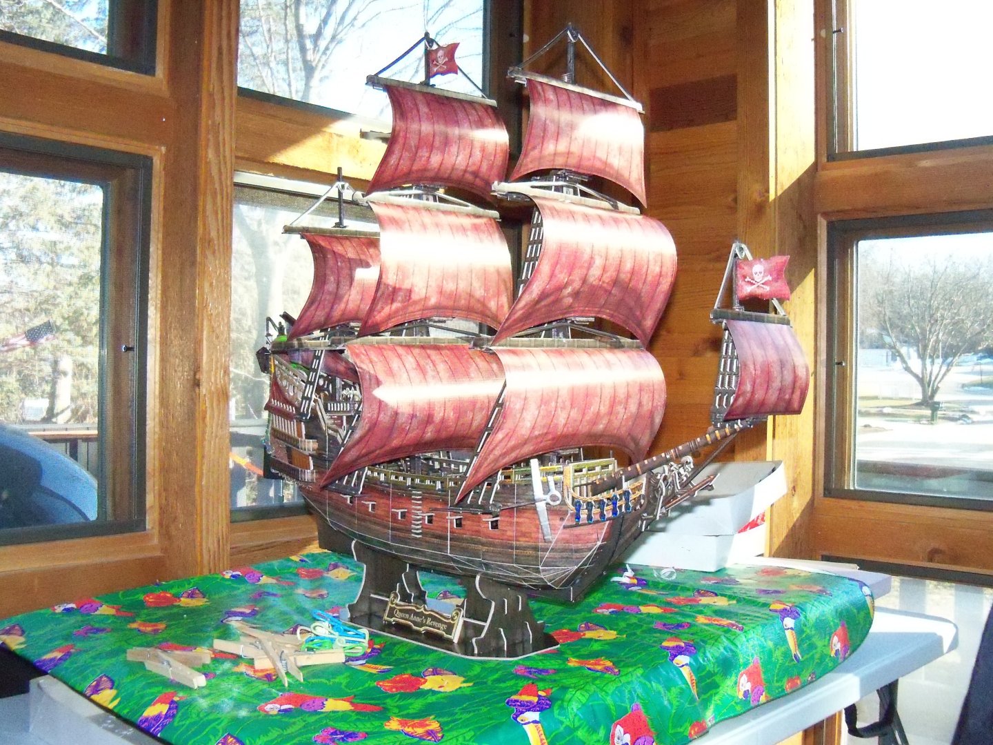
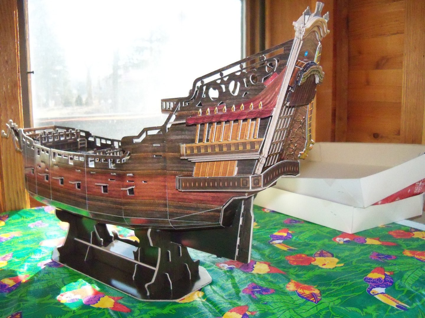
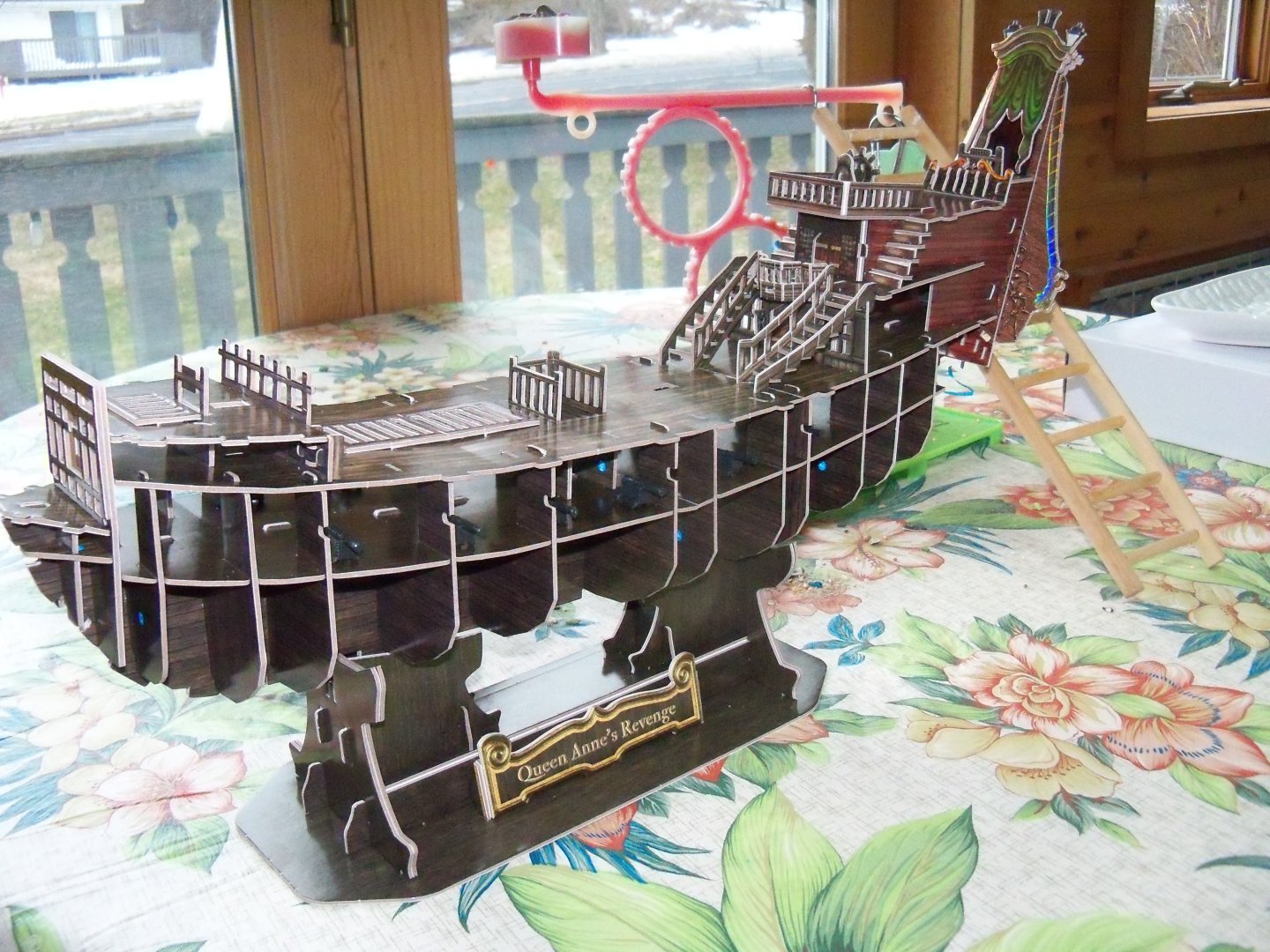
She was thought to be a three masted frigate of approximately 200 tons, that measured 103 feet long with a beam of 24.6 feet. Originally operated as a slave ship operated by René Montaudin, a leading slave trader of Nantes, until it was sold in 1713 in Peru. She was briefly operated by the French Navy in November 1716, but was sold by them for commerce five months later in France as a slaver once again. Then in November 1717 she was captured by Edward Teach (AKA Blackbeard the pirate) near the island of Saint Vincent in the West Indies. After Blackbeard and his small fleet of pirates sold her cargo of slaves at Martinique, he gave her the name of Queen Anne’s Revenge. He made her into his flagship and added more heavy cannons. (For a total somewhere between 30 and 40.) He continued to operate her and his small fleet for less than a year in the Atlantic Ocean between the west coast of Africa and the Caribbean, attacking and capturing numerous British, Dutch, and Portuguese prizes. Then in May 1718 while attempting to blockade Charleston harbor in North Carolina, his flagship ran aground while entering Beaufort Inlet. Despite efforts to kedge her loose by one of his smaller ships, the sloop Adventure, he decided to disband his small flotilla, transfer supplies to the smaller ship and make his escape. Several of his crew members were stranded on a nearby island, who were later rescued by Captain Stede Bonnet. He ended up surrendering shortly after that and accepted a King’s pardon for himself and his remaining crewmen from Governor Charles Eden at Bath North Carolina. However, he soon resumed his career as a pirate and in November 1718 he was killed in combat. On November 21, 1996 a shipwreck was located by Intersal Inc., that laid in 28 feet of water about one mile offshore of Fort Macon State Park, Atlantic Beach, North Carolina. They believed it to be the remains of Queen Anne’s Revenge. After much research and recovery of artifacts from the wreck, the National Geographic Society finally confirmed on August 29, 2011 that it was indeed that ship. During the interim while they were still trying to confirm its identity, it was added to the National Register of Historic Places in 2004. The site is now owned by the State of North Carolina and located South of Beaufort Inlet. As somewhat of a side note to this ships history, the Sunset, a replica of Queen Anne’s Revenge, was used in numerous roles in the Pirates Of the Caribbean films.
- 9 replies
-
- 2
-
-
- Queen Annes Revenge
- CubicFun Toys
- (and 1 more)
-
I previously posted a review of this model kit back on January 4 th of this year. I took numerous photos of it during the process and have decided to post this build log for it. First, I'll give you a bit of its history and details of the actual ship. While there are no confirmed records of the date and place of construction it is generally assumed to be around 1710 since there are no records of its activities prior to that date. She was a three masted frigate of approximately 200 tons, that measured 103 feet long with a beam of 24.6 feet. Originally operated as a slave ship operated by René Montaudin, a leading slave trader of Nantes, until it was sold in 1713 in Peru. She was briefly operated by the French Navy in November 1716, but was sold by them for commerce five months later in France as a slaver once again. Then in November 1717 she was captured by Edward Teach (AKA Blackbeard the pirate) near the island of Saint Vincent in the West Indies.
- 9 replies
-
- 3
-
-
- Queen Annes Revenge
- CubicFun Toys
- (and 1 more)
-
Perhaps I can provide some personal insight on this concept Gregory. See my build log for the whaling bark Wanderer in the Kit build logs for subjects built from 1851 – 1900. The 1/87 scale plastic model kit is made by Aurora and I am heavily modifying the kit, by replacing most of the plastic parts with wood, including the ships deck.
-
The African Queen. My First Listing and First build here.
BETAQDAVE replied to a49kid's topic in New member Introductions
I would use a strip of double sided tape to hold it in place. Others here use a temporary adhesive followed by a release agent. I'm sure there are probably other methods that are covered in the shop notes area of our forum. -
I could suggest another possible option here Ron. Before I throw out old appliances or tools, I always disassemble them and salvage anything useful, especially if they can be used for models. If you have a small old electric motor driven tool that you no longer use, you could use some of that fine copper wire that's wrapped around the armature. The smaller the motor, the finer the wire. If it's disguised as rope and it needs to be draped, it can easily maintain the curve and there is no fuzz to deal with.
-
Brig Le FAVORI 1806 by KORTES - 1:55
BETAQDAVE replied to KORTES's topic in - Build logs for subjects built 1801 - 1850
That is probably true, but it just makes your results just that much more remarkable! My paternal grandfather was also very good at carving by hand back in the depression with his own handmade tools. I was always impressed by how he could create such beautiful sculptures and furniture from the most basic tools and scraps of lumber that he could get a hold of. I think that's who I inherited my urge to recycle rather than replace from. -
Brig Le FAVORI 1806 by KORTES - 1:55
BETAQDAVE replied to KORTES's topic in - Build logs for subjects built 1801 - 1850
That's a very remarkable improvement on such a small detail! -
Looking at the box art photo, they appear to do just that. On the actual ship I'd be willing to bet that the rubbing strake was trimmed back where they overlap. Otherwise, replacing the portholes would be next to impossible.
-
One begs to ask the question Ian, just how heavy is this beast going to get when its fully loaded? Looks like you might need to get pumped up at the gym first to launch and recover it. 💪🏋️♂️
- 536 replies
-
- 2
-

-
- Quadrireme
- radio
- (and 1 more)
-
Welcome John, hope to see some of your work here soon.
-
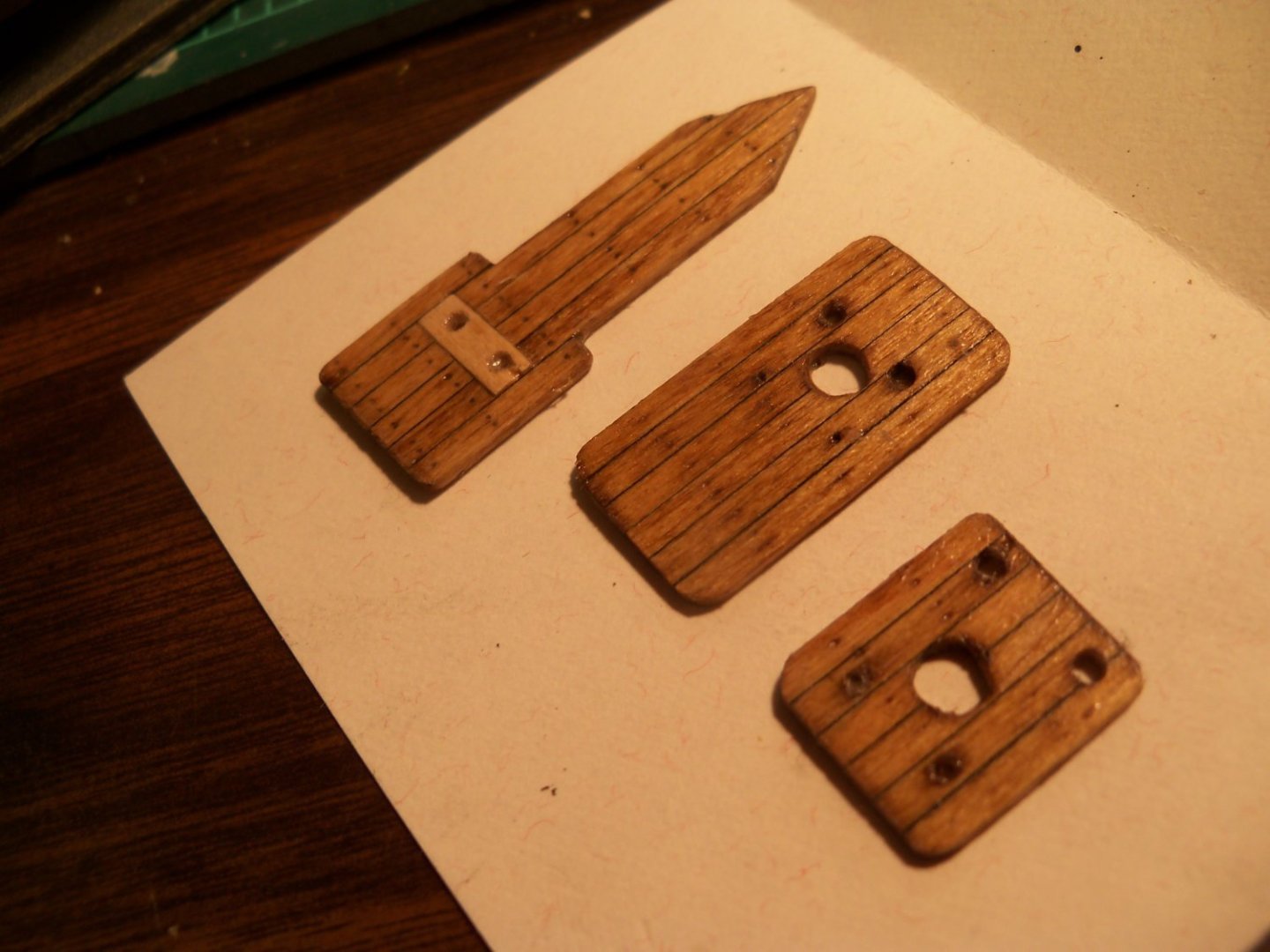
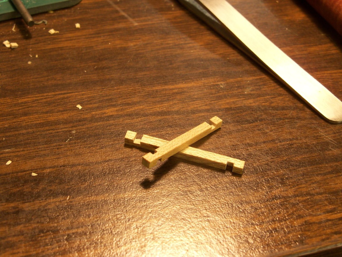
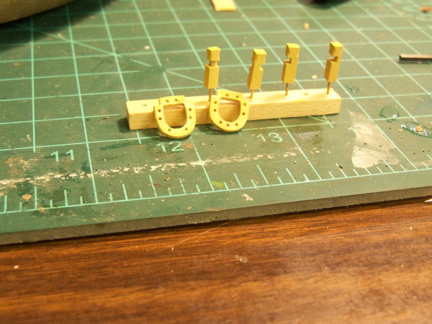
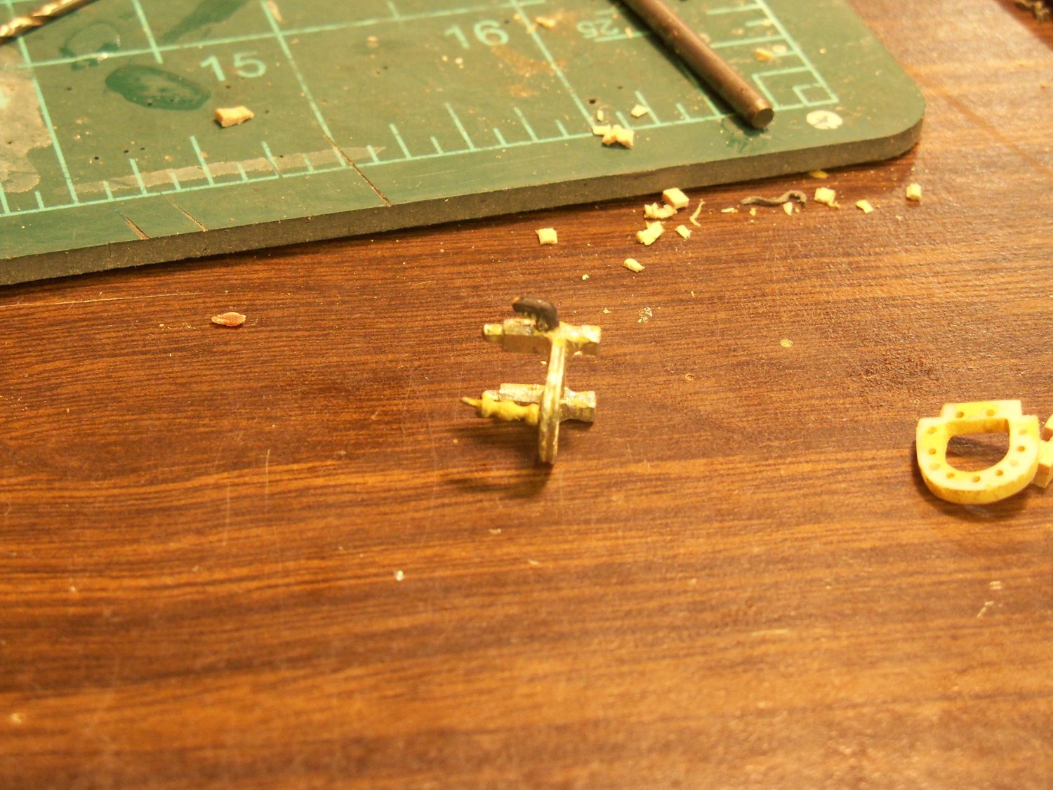
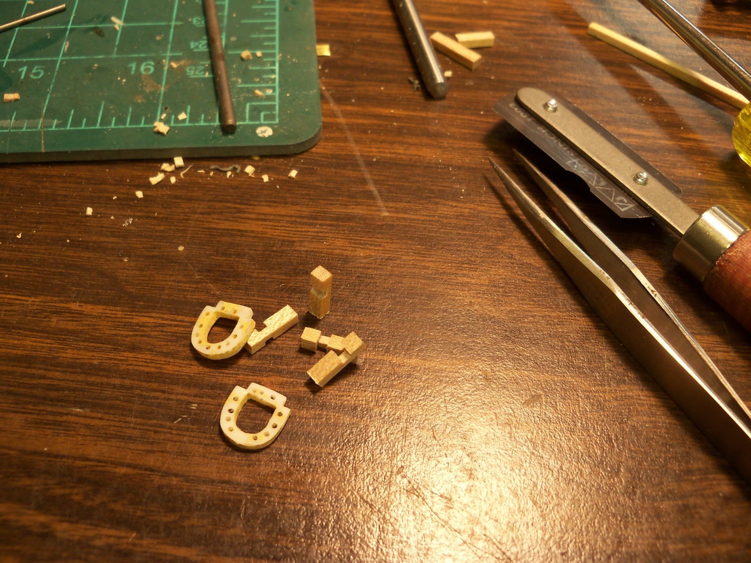
Having recently reviewed the scratch build log of Phantom 1868 by victory78 – New York pilot boat, I was intrigued by how much more can be shown at his larger 1:50 scale version. Most notable to me was the differences between the plans provided by the Model Shipways kit and his version. While I have no way of determining which version is correct, I suspect that since his version seems to include a lot more details that don’t appear at all in my kit plans, I’ll go with his version. One example of this was that the waterway and the margin plank on the foredeck are indicated as separate features on his, as opposed to the kits’ version of just a single plank. I’m not sure, but perhaps the kits’ smaller scale led to them to just simplify it. Another notable feature that his version added, that seemed like it would have been a logical thing to see on a ship like this, was the reinforced deck doublings in the areas around the mast holes and bitts. It seemed so logical in fact, that I decided to include them to my version, especially since they seemed to be an easy feature to add. Since my bowsprit was not yet permanently attached, it was pulled out first to allow adding the doubled deck for the winch bitts. I made up these three somewhat simplified versions of the doubled decking area add-ons as shown below. You can see that I even included a version of his contrasting body wood for the winch bits, but was unable, at my scale, to make them separate pieces. So I just compromised, and was able to combine the two into one. He also made body wood for all of the deck projections, but once again, with the difficulty of working at my much smaller scale, I decided to skip the remaining projection trim. (I think that if I had known about them earlier in my build, I might have included them, but that’s water under the bridge now.) After completing the doubler decking sections and test fitting the winch bitt with the bowsprit reinserted, I discovered to my dismay that the bitts had been placed too far back from the bow and the extra thickness of the decking had also lowered the angle of the bowsprit! Once again it was back to doing some more damage control. So the pointed bow end of the doubling deck and the heel end of the bowsprit were both shortened, and the bottom cross beam of the bitts was filed down until the proper angle was restored. Whew! But wait for it… when test fitting the fife rails, I also discovered as you can see below that the spindles included with the kit were 0.16mm too tall and caused the rails to be tilted! It seemed like if I found one thing that needed correcting, something else also had to be changed. Comparing my wood bitts to the metal fitting that came with the kit, they were a match size wise. Which only left two possibilities. One, the spindles provided were too tall, or the fife rail fittings were too short. At least the error was apparently not mine. But, since the metal spindles couldn’t be shortened, I had to add 0.16mm to the bottom of the posts. Since I was never quite satisfied with the previous fife rail posts anyway, I wasn’t all that bummed out about it. Unfortunately, while taking my glued up fife rail fittings apart I broke one of the plastic rails, which would have been the hardest part to reproduce. Luckily it only broke into two pieces, so all it needed was to be glued back together. So I ripped down a couple more 3/32” x 3/32” maple strips as shown here and cut the notches for the fife rails as I did originally. Rather than filing a peg at the bottom of the posts again, I decided to add that missing 0.16mm to the bottom and to cut them off at 10mm and drill a hole into the bottom for a 10mm long 0.62mm brass nail with the head filed off. Which left about 6mm exposed to go into the deck. Since all of my light buff deck house paint from Model Shipways came out of the jar the consistency of a hockey puck, I ended up grinding it down and added enough water to get it somewhat usable again. The first time around I had made the mistake, of gluing the fife rails together prior to painting and as a result, the assembled fitting was very hard to sand between coats and the resulting finish was rather poor. So this time I painted all of the components before assembly to make them easier to sand between coats. Of course my paint was so watered down now, that I had to use six coats with light sanding between. I did manage, however to get a much smoother finish this time. While I had been careful to avoid getting paint into the notches, I forgot that the wood might still swell a bit from so many coats of watered down paint. So, another test fit was done, and sure enough, the notches had to be lightly filed for easier assembly. Now all I need to do is add the half cleats and reassemble the fife rail fittings for later installation on the deck. My next posting will cover making the navigation lights and the portable anchor davit.