


allanyed
-
Posts
8,149 -
Joined
-
Last visited
Content Type
Profiles
Forums
Gallery
Events
Posts posted by allanyed
-
-
Ian,
The names were painted on the ships, some plain, some not so plain. Printing them as described above, on THIN paper stock that is the same color as the counter is a good idea, but you can also make a thin paper template, paint it the same color as the counter, then paint the name. After drying, glue onto the counter. David Antscherl goes into great detail on how to do this in TFFM.
Allan
-
Chuck,
I have used thinned acrylics and I do like the results, but I prefer using several coats of India ink. There are no brush marks, it penetrates well and maintains a consistent matte finish.
Allan
-
Ed,
Cudos.
Ahh, the lowly single edge stiff back razor. A fresh one for scraping deck planks, snipping ends as you show, and then grind a profile in the dulled ones to use as a molding scraper. A rather useful, yet inexpensive little tool for sure.
Allan
-
Hello Newton,
Please take a moment to introduce yourself in the new members forum.
As the Santa Maria was a Carrack , a possible source for the information you are seeking is Magellan's Victoria replica which was a Spanish Carrack. The replica was built in 1992 in Japan. I have no idea how much similarity there would be nor how accurate the builders of the replica were, but I would guess they studied it intensely and were more accurate than many, kit manufacturers.
Allan
-
Atta Boy Ben!
Druxey convinced me to try stiff card stock and illustration board a long time ago. It is cheap and easy to cut into pieces and make into a variety of jig fixtures. Ply works as well of course, but more costly and needs more than scissors to cut. Then again, plywood is likely to last longer for future use.
Allan
- alangr4, Trussben and billocrates
-
 3
3
-
For the most part, don't make or rig sails if it is not necessary, imho. Even at 1/4 scale, any sewing, be it hand or machine, will more than likely not be to scale and not look good. I have made and rigged sails on several schooners because the client required them otherwise would never have considered it. I used 1200 count Turkish linen sheets. That thread count was as close as I could get to scale, but it does have a sheen to it. It ain't cheap. Two pillow cases gave enough material but was close to US$40, on sale. Our bed sheets are not even close to that quality.
If you can find silk span it is thin enough to be to scale at least down to 1/4, maybe smaller. It used to be available in three thicknesses, but I have not seen it readily available since shrink plastic took over the model airplane field quite a few years ago. I did a quick search and it is apparently still out there, if not in the neighborhood model shop as in the past.
Allan
-
First thing that came to my mind is as Nigel and others have posted. Further, some adjacent planks end at the same spot. I don't believe there would ever be two adjacent strakes with butts on the same frame, so this reinforces the idea that this is the builders way of showing off his framing.
Allan
-
Super photo, super build!!!!
Allan
-
Cudos Danny.
I do not recall seeing mention of it earlier in your build, but I may have missed it. What materials are you using for trennals, bamboo or something else?
Thanks for continuing to share your build.
Allan
-
Great explanation Ed, thanks!
Allan
-
Ben
Are you going to add all the ports as you make and install the frames? I know there are those that do this and do it well. Heck, I have a hard time making them lie in the correct and fair line when marking and cutting them in a finished framed hull. Cutting the notches in the frames for the ledges and lintels is far easier when doing so off the model, but alignment, for me at least, is not at all likely.
Overall though, it is coming along very well. I wish the "net" had been around when I did my first few scratch builts and could get the mentoring available at MSW.
Allan
- billocrates and butch
-
2
-
Ed
The detail you always show is really quite something to behold. Your engineering background certainly shows through in the attention to detail.
In your research, were the hanging knees called out as hanging knees or hanging standards as would often be called on the older English ships when the knees were directly under the beams versus fayed to the side of the beams?
Are you marking the location of the knee on the side or underside of the beam once the knee is temporarily pinned in place so you can glue it off the model? There is so little room to work, I am curious as to how you are locating the knee to get such a neat fit against the side of the hull especially in that they all have a slight taper to follow the shape hull fore and aft.
Your build continues to be a learning experience and fun to watch. As always, thanks for sharing.
Allan
.
-
Remco
The Fiebings dye was a new one for me. Thanks for sharing that information. Do you or does anyone else on the site have long term experience with it regarding fading or effects from long exposure to sun light, etc? If you posted more on this product earlier, I missed and thus apologize for the question.
Thanks again for sharing, your model is terrific.
Allan
-
Ed,
All the best complimentary words have been used. This model deserves a newly coined term for exemplary.
Keep the pics coming, please.
Allan
-
Gary,
The only suggestion I can make regarding the lumber is to get the set for Euryalus from Jeff Hayes at the Hobby Mill. When we did the book and plans and build, it was over several years but I did not keep track of the lumber quantities used. I started with rough cut wood and cut my own stock but if you do not have the tools, the Hobby Mill set is a great way to go.
Allan
-
Ciao Bruno
There are a few that I found on the NMM website in the collections section using "24 gun" as the search term. I did not see any of the Pandora. Then again, maybe Pandora was not the same as the others regarding the rabbet. No matter, your model is looking extremely good!
Allan
-
Bruno,
I am very sorry, but I am not sure I understand your comment/question. You mention a direct question so please feel free to ask or PM me if you prefer.
(If you are in the area of Croatia that speaks Italian, feel free to PM in Italian. Half my coworkers are fluent in Italian.)
Allan
-
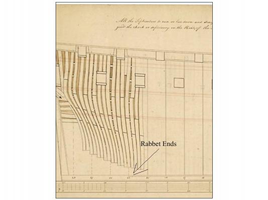
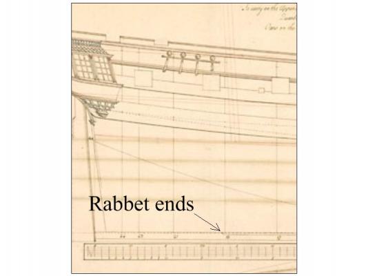
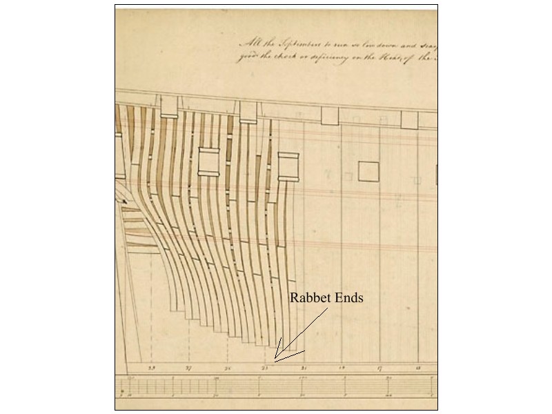
Bruno,
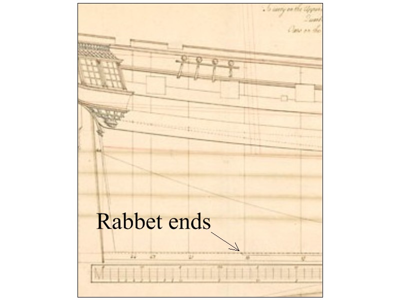
Your workmanship is beautiful. I do have one question regarding the rabbet on the keel. Should it go all the way to the stern post? Of the few NMM drawings I have seen, it usually stops several stations forward of the stern post. See attached. Sorry these are not super clear. You can find them in the collections section at the National Maritime Museum site for a clearer version. Crescent is from 1779 and Mermaid from 1749.
Thanks for sharing your build.
Allan
-
Jabe
The three threads are the strands used to make the rope itself. Thread is,,,,, well, it's thread. It does not look like rope except maybe at the tiniest sizes.
Allan
-
Vossy,
Whether you use one long strip or in shorter lengths, the width is an issue in that it is supposed to change, especially between the dead flat and the bow. Each plank should narrow as the space for the planks reduces the closer you get to the bow. Look at the cross section at the dead flat and another cross section toward the bow. If you do not do this there will be too many drop planks. The stern has the opposite issue in that the planks often need to get wider, or stealers need to be added.
Check out http://modelshipworldforum.com/resources/Framing_and_Planking/plankingprojectbeginners.pdf This should help.
Allan
-
Thanks for the cudos guys. I sent a note to Bob at Seawatch last night as there is an error on the website. The blurb states tables from the various sources, including the 1715 Establishment. That should read the 1719 Establishment. It has a table with the 1719, 1745 (and 1750 changes to the 1745) in one set of tables and the Shipbuilder's Repository and MOST of the Elements and Practices tables by Steel. It does not have the merchant navy dimensions given in Steel but it does include separate tables with scantlings for boats and another for anchors.
Allan
-
-
Jeff at the Hobby Mill is providing a heck of a great service to those that need precut wood and I would use his service if I did not have a plainer and thickness sander in my little shop at home.
If you can start with rough cut pieces, two other suppliers from whom I have purchased wood over the years and recommend are Exotic Woods in Burlington Ontario (bought from them at their place when driving to Toronto) or Gilmer Woods in Portland Oregon which was strictly by internet and mail. Over the years the savings of sizing my own wood has more than paid for the plainer and thickness sander.
Allan
- WackoWolf and themadchemist
-
2
-
Hi RAFTERRAT2006
It would be nice to have a name that we can call you. Thank you.
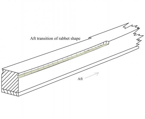
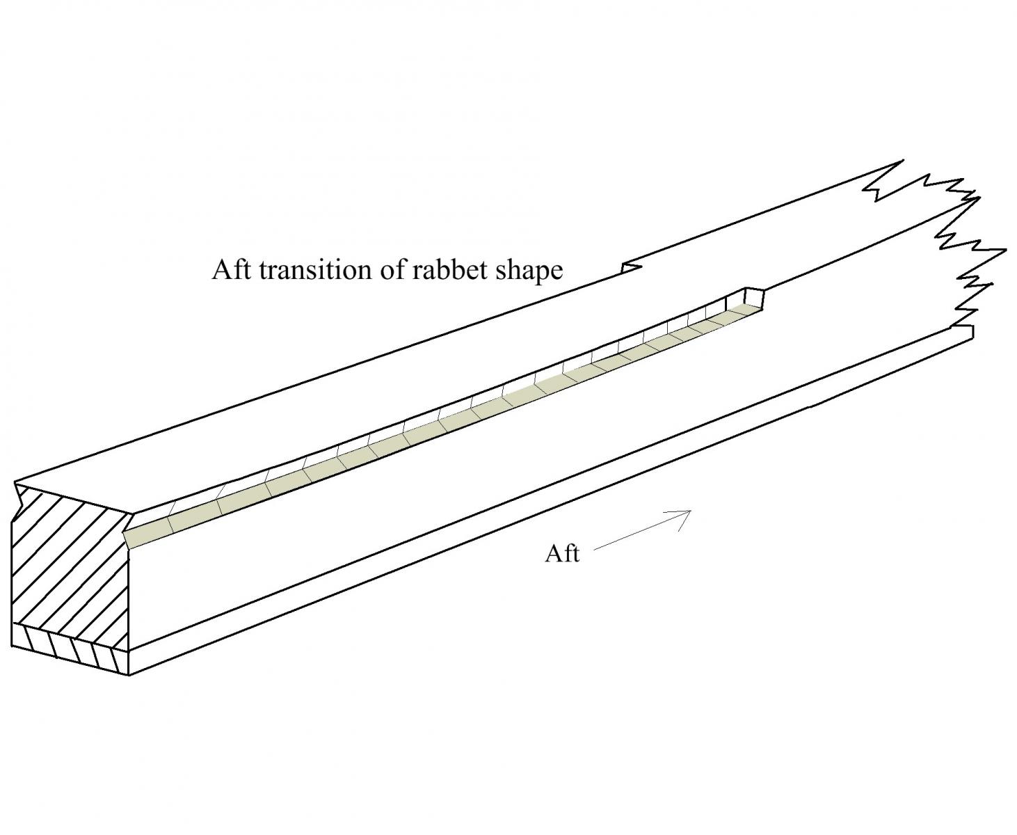
The rabbet is not a vee groove for the entire length. It is a dynamic groove that matches the lay of the garboard strake for most of it's length. It continues to change as it rises at the bow to match the angle at which the planking will land in the rabbet. Near the stern it is virtually a vertical "L" shape . As far as how to make the groove, I start with a vee chisel as described above, but for only a shallow cut. I then go to a small, extremely sharp flat chisel to finish the rabbet. Be sure the keel is secure on the work bench so you can control the chisel with both hands. The attached sketch may be a better explanation.
Allan

New Scantling book announced by Seawatch books
in Book, Monograph and Magazine reviews and Downloads. Questions and Discussions for Books and Pubs
Posted
Bob at Seawatch Publishing posted the news that the book of scantlings is now available to anyone interested. The Seawatch website gives a good bit of detail but I thought it would be a good idea to let anyone interested know a little bit about the book.
This is not a novel. If you have trouble getting to sleep at night, it will work better than most drugs to fix that problem. BUT, if you are a model builder, especially scratch builders and kit bashers, there is information all in one place that required a rather extensive and expensive library up until now. Over 200 pages of the book are tables of British Naval ship scantlings and dimensions, including:
A.) 1719 and 1745 Establishments and the 1750 modifications to the 1745 Establishment.
B.) 1788 Shipbuilder's Repository and Steel's Elements and Practices of Naval Architecture scantlings for ships from 110 guns down to 10 gun brigantine. Merchant vessel scantlings were not included because there just was not enough room.
C.) Boat scantlings from Steel
D.) Anchor scantlings from Steel
E.) Drawings showing many of the items listed in the scantlings.
I hope this will turn out to be a helpful source to many of you.
Allan