


Arthur Goulart
-
Posts
59 -
Joined
-
Last visited
Content Type
Profiles
Forums
Gallery
Events
Posts posted by Arthur Goulart
-
-
On 1/3/2026 at 6:16 PM, druxey said:
Fascinating. The 17th century English fashion paice was set is a similar way and, by the end of the 1600's, the two radius stem was also used, although sometimes in a slightly different way. Usually the lower radius ran smoothly to the keel. In other examples there was an angle at the forefoot as your example.
On 1/10/2026 at 7:12 AM, Martes said:It's called estain and is quite common on French plans (but encountered on others as well).
You two are absolutely right. Danish practices, again, find their pairs in other nations.
I looked at Duhamel du Monceau's treatise, and on p. 228 he describes how the estain is drawn, and, much like what is seen on these Danish plans, the different lisses end at the estain. Thanks a lot Druxey and Martes!
-
19 hours ago, TJM said:
Yes, this is also what I conclude based on the evidence I have seen so far. And yes, no matter what, this build will not be a truly faithful representation of Christiania - it cannot be with me adapting the Sphinx kit. All of the deck furnishings will be 1:1 the Sphinx setup. So I guess I can take the liberties I want, but I still have to decide what I prefer 😅
The comment about the painting of the ships comes from Danske Orlogsskibe 1690-1860 (a fantastic book!):

This translates to:
In Gerner’s period, the painting of ships was introduced in the Danish navy. This came about almost through a private initiative, as the commander of Sophia Frederica in 1781, A. F. Moltke (1748–1820), at his own expense had his ship painted. The following year, the commander of the Indfødsretten, in connection with sailing to the Mediterranean, requested permission to do the same. The commander of Holmen had now come to the conclusion that painting was more preservative than the ordinary tallowing that had previously been used, and therefore had the painting of all Danish ships of the line carried out.¹¹
Previously, the ships had been “blacked” with a mixture of thin tar and soot, something that gave the ships a dark brown, almost blackish appearance. According to the regulations, this applied only to ships of the line, while the frigates were occasionally treated with pine pitch. When the blacking and pitch-coating took place, care was taken to cover tarpaulins over the “externally painted ship ornaments” in order to avoid blackening them.¹²
Reference 11 is to a text by F.C.Kaas published posthumously in 1843 who recounts the work that was done while he was Chief of Holmen (the Navy shipyard in Copenhagen) from 1781-92
That's awesome how it's possible to precise a date like that, thats more than a decade later from the adoption of paint by the British.
Also, just the other day, I was wondering what they finished the wood with when it was left unpainted, and, there it is! I'd be curious to know if there are photos of oak finished by those methods, so to see how it actually looked back then.
Thanks a lot, @TJM, you've taught me quite a lot these last interactions!
-
Interestingly, as well, on Fyen's model the black goes up the wales, which makes sense. On Fyen's case, if the black was restricted to under the wales, it would be a thin, odd looking, section. Now, analysing it with that in mind, Falster, unlike the one deckers on the image I posted above, does not show the black outlined upper wale strake edge, as to suggest Falster is represented with the same scheme we see on Fyen. So, to summarize the conclusions from these few evidences: for frigates and smaller vessels, as the wales were relatively higher to the waterline, the black ended just below the wales, while for ships of more decks, the lower wales would too be painted black. Makes sense to me.
And, TJM, you can always say that the model represents Christiania later in her career, by then she would've been yellow. You've hooked my interest though, why did you come to the conclusion that the yellow came sometime in Gerner's period, not before?
-
TJM,
You're right.
I had overlooked the posts about the black starting under the wales, but there is substancial evidence it did, specially when comparing Søe Ridderen's painted depiction you showed a couple times already on the topic with the ship's sheer plan, as you've noted too.

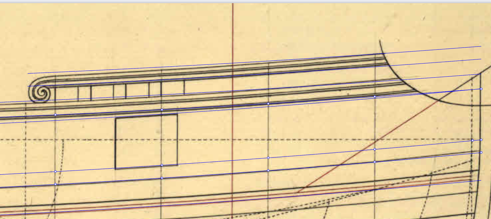
Furthermore, take a look at this illustration:

Doqven, Chistiansborg, BlaacHejeren, and Falster, all show the outline of the step of the upper wale, and the black portion, which follows the contour of the outlined step. That shows both awareness of the naval painting pratices of his time and intention to reproduce them by the depiction's author. And on Friederich et Lovise and on Neptunes, on which the wales were seemingly not blended with the hull, the black starts even lower.
Grant it, these are earlier examples than Christiania, but, that's some further evidence to think about.
Best regards,
Arthur.
- hollowneck, TJM and Thukydides
-
 3
3
-
TJM, the shape modifications definetely show!
I have a suggestion for you, on the topic of planking. One important detail that differs Danish from English practice would be the wales. While they were blended with the hull planking downwards, the upper wale's edge should stick out, where it meets the thinner planks towards the gunports:
That should be along the transition between the yellow cedar and pear on your model. Grant it, it would be extra work, but, besides being a historically relevant feature, the wale's step would make a good division between the different woods.
Also, if you decide to attempt that modification, keep in mind that the wales should tuck in at the stem, meaning that the step would be no longer visible along where the hull planking meets the stem, if that makes sense.
Cheers,
Arthur.
- hollowneck and TJM
-
2
-
-
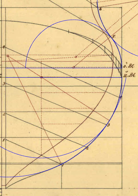
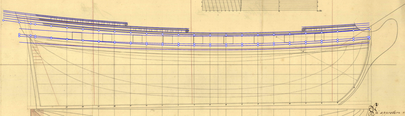
STEM, STERNPOST AND THE FASHION PIECE DIAGONAL
Moving on, let's take a look at how Turesen drew the stem on these designs. The first important point of reference will be where the temporary curve that is drawn parallel to the gun deck to define the lower edge of the gunports ends at the inner stem perpendicular. I couldn't find for this point of reference (as is the case for the point where the deck ends at the same perpendicular) a precise proportion that defines its height, though it looks like Turesen aimed for something in between 0,18 and 0,19 of the ship's lenght for all three Hvide Ørne, Wildmanden, and for the A1246c brig, measured from the rabbet of the keel.
From this point, a line is drawn aftward, parallel to the waterline, of same lenght as the ship's breadth, and its end will be the center of the upper radius that forms the stem. From the same center, a smaller radius is set, that measures 1/3rd of the breadth. Now, from the given distance for the stem's rake (forftevnen falder), a radius of 2/3rds of the breadth is drawn, and its intersection with the '1/3rd of the breadth radius' will be the center of the lower radius that forms the stem. The upper radius is the same lenght as the breadth, and the lower radius is 2/3rds of the breadth.

In green, the upper and lower stem sweeps. This geometric process is done so the lower stem arc is tangent to the upper one.
The sternpost also is set from a point of reference that relates to the lower edge of the gunports curve. Its inner rabbet line is set from two points: the given sternpost rake (afterftevnen falder); and, the midpoint between where the lower edge of the gunports curve ends at the inner sternpost perpendicular and where the gun deck ends at the same perpendicular. The outer rabbet line is drawn parallel to the inner one. The outer edge of the sternpost, however, is not simply parallel to the rabbet lines, it is narrower on top than it is down, so it is set by two points, one that is measured, on the rabbet of the keel (same as the given sternpost rake), and one that is measured up on the outer sternpost perpendicular. In Wildmanden's case, measured from the rabbet of the keel, that second reference point is the same height as the height where the stem ends its rake (aka, the height of the center of the upper stem radius).

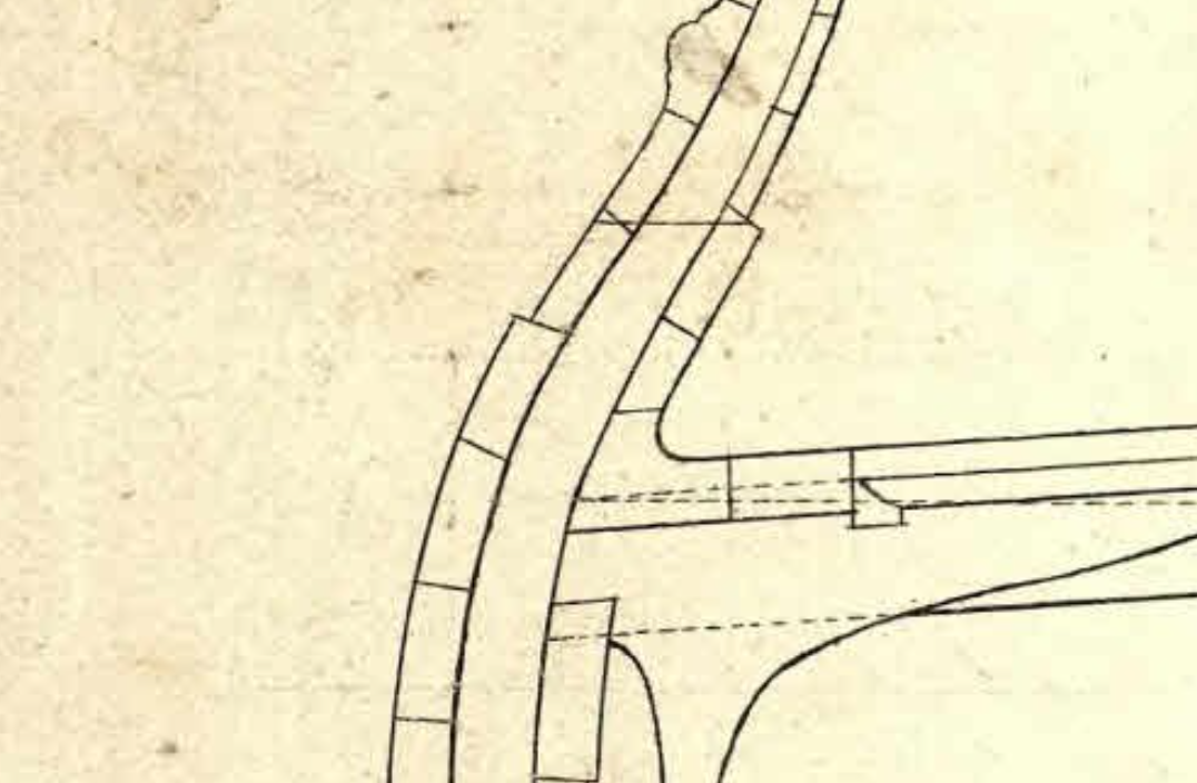
Now, what I think is the most valuable part of today's post, what I'll call the fashion piece diagonal, for a lack of nomenclature for it (not that I know of, at least), and so it's not confused with the transom. I'd love to hear your thoughts on it, but I don't think I've seen this type of construction from plans of other nations, not English, not French, not Swedish, nor Dutch. What is usually seen on body plans is a perpendicular cutout view on the position of the aftmost frame that is parallel to all other represented frames of the body plan. That is not the case with Danish drawings of this period, the aftmost cutout seen on them runs along this fashion piece diagonal, and thus is not perpendicular to the water level, like all others. Interestingly, all aft frames will be later formed by referencing the shape given to this oddly inclined cutout.


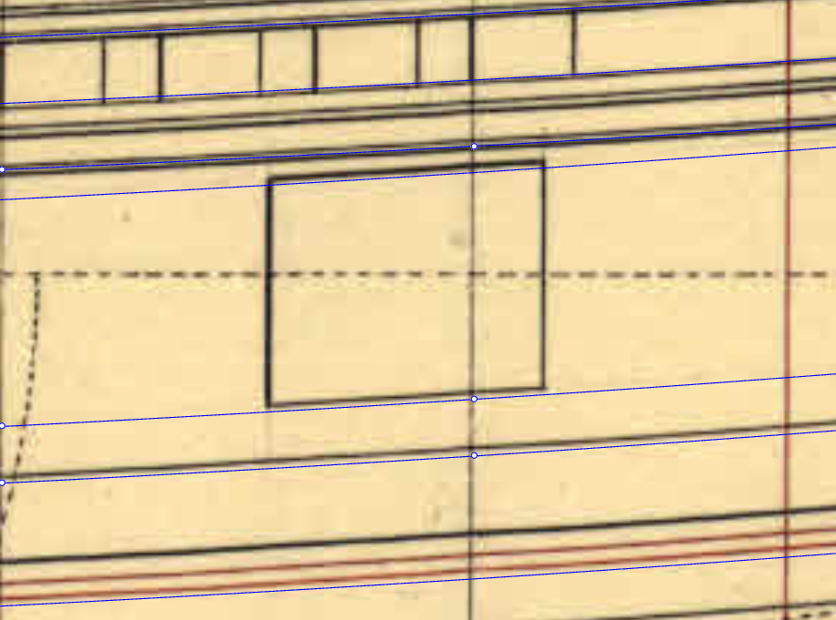
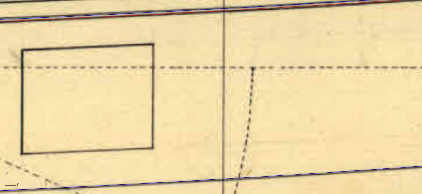
So, how is it set? Again, by two points. The lower one will be the width given to the lowest transom beam, measured from the inner sternpost rabbet. In Hvide Ørne's case, a simple 3 feet, or 2 feet for the A1246c brig. The upper point will be where the rise of breadth ends, and is set similarly to what we saw for the sternpost inner rabbet: the midpoint between the lower edge of the gunports curve and the gun deck. That is described on the A1226e Wildmanden plan, under Speilets Construction: "Største Breeden reiser til Medium imellem underkanten af Forstævnen og Dækket" (The greatest breadth rises to the mid-point between the lower edge of the stem and the deck). The 'lower edge of the stem' being the lower edge of the gunports curve. Possibly @TJM can give us a better translation for it. Instead of that midpoint being taken at the inner sternpost perpendicular, as is the case for the inner sternpost rabbet, however, it is taken at a certain distance from it, as is represented by a perpendicular on the A1246c brig plan:

In conclusion, this is what we have:

For all similar Turesen designs (the two frigates, the brig and Fredericus Quintus), the resulting angle for this fashion piece diagonal is very close to 70º, relative to the waterline. The actual transom is parallel to this line.
Happy new year!
-Arthur.
-
On 12/24/2025 at 1:21 PM, TJM said:
Very nice Arthur! Hvide Ørn is a very pretty ship indeed!
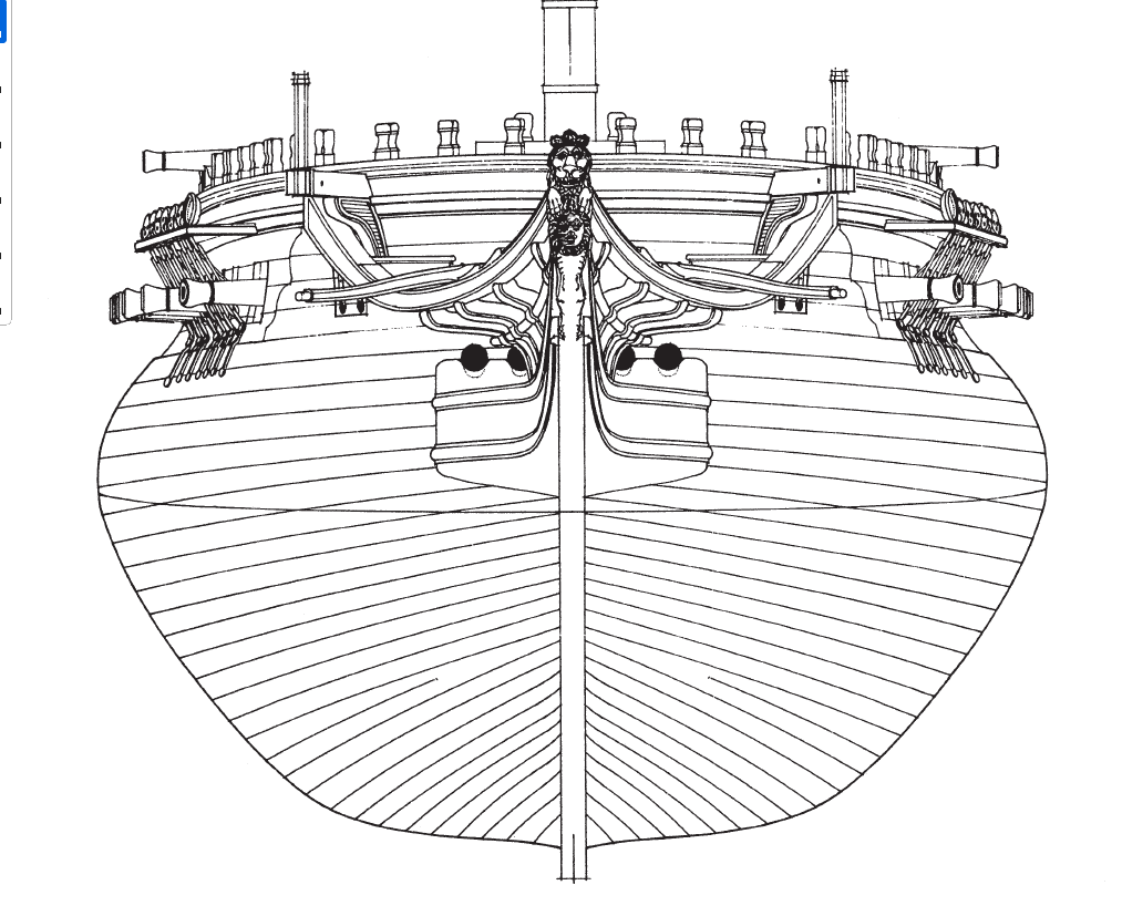
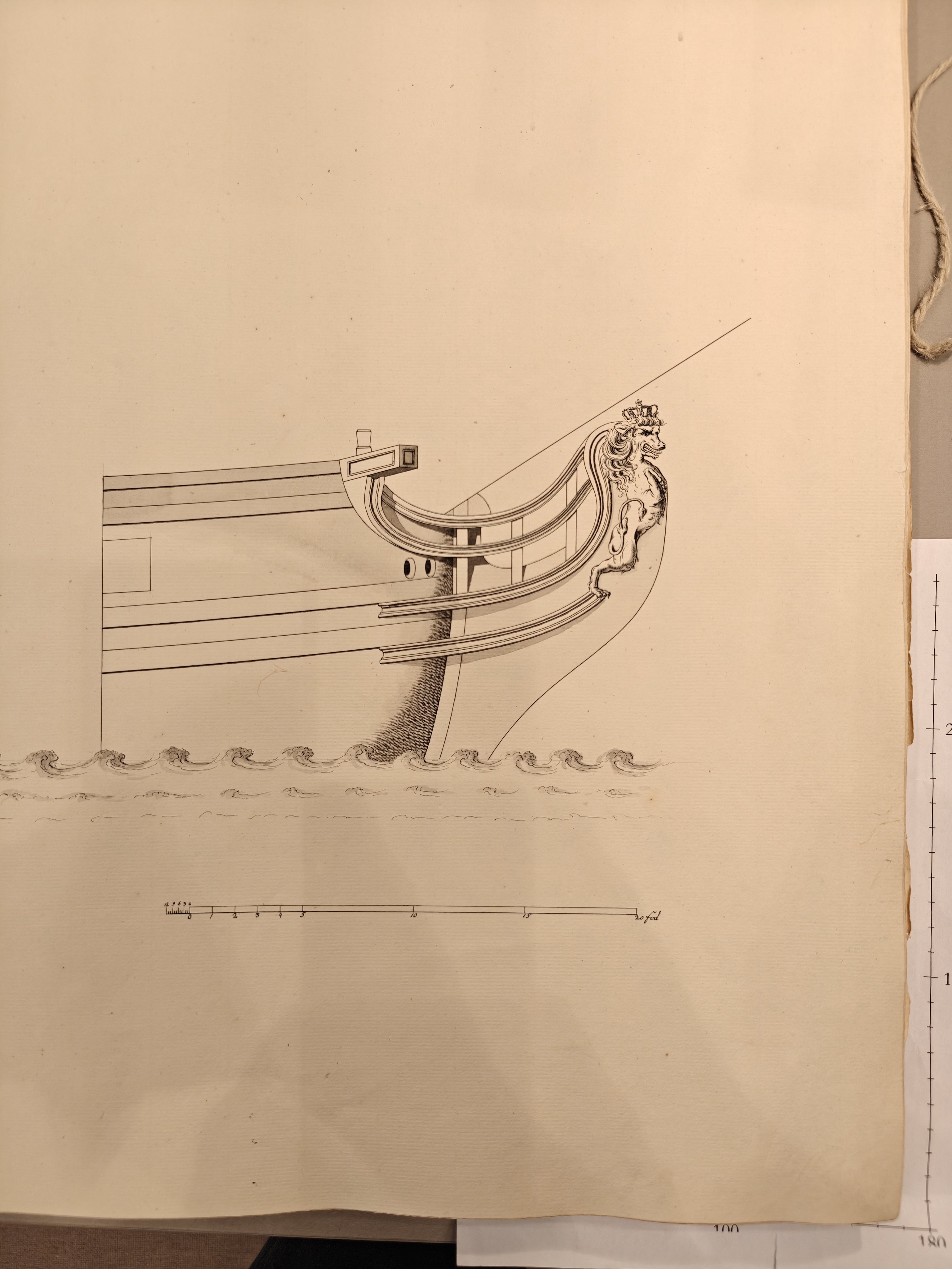
Here's a slightly more detailed image of the figurehead that I took at the Danish National Archives:
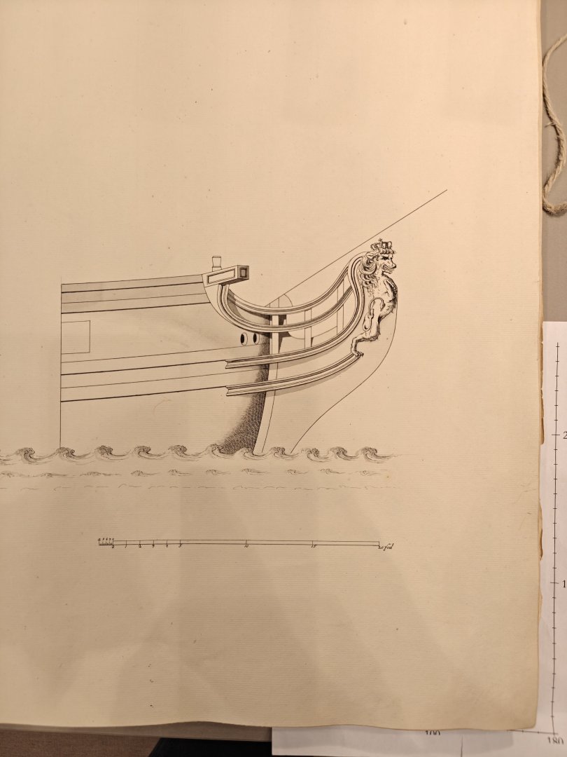
This particular copy of the original had not been scannet yet. It is designated H18.
I really appreciate it, @TJM! And thanks for the explanations regarding the drawings you gave me in private messages!
-
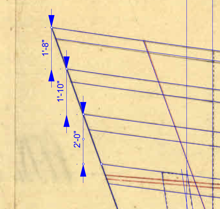
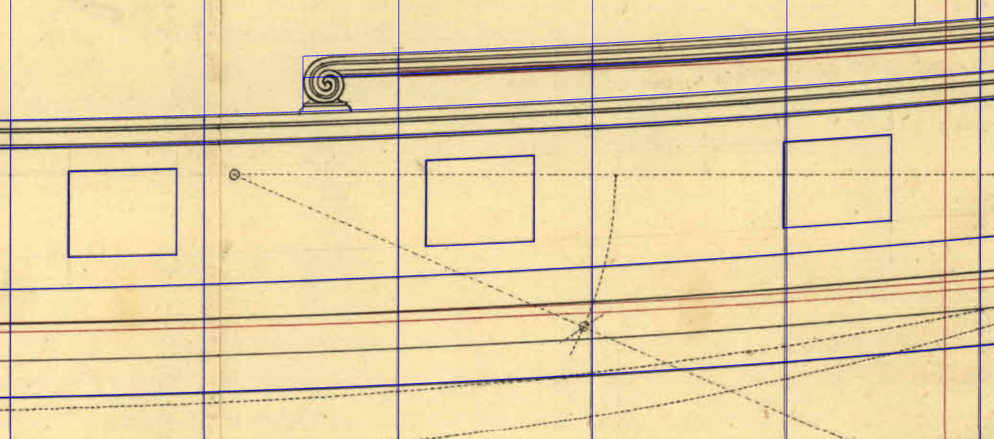
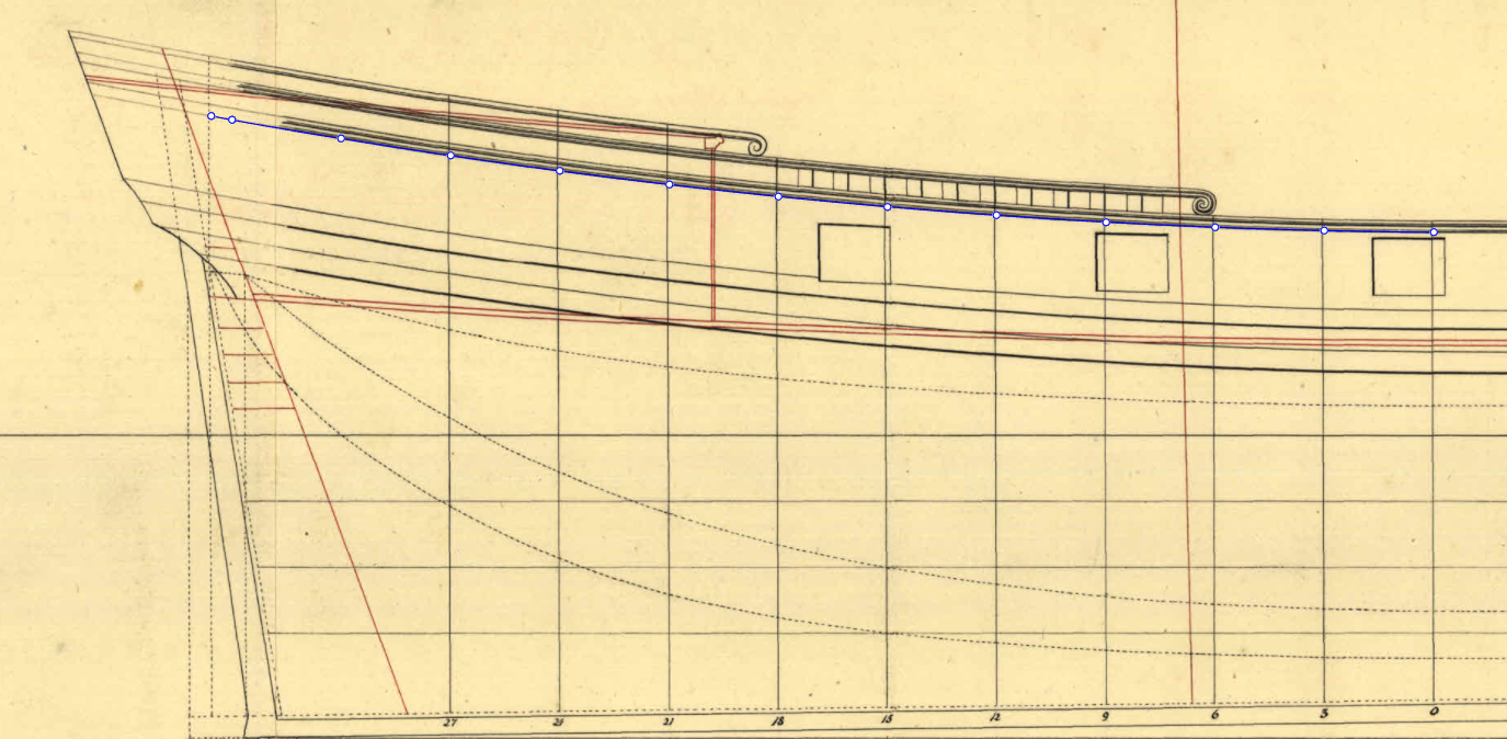
The sheer curves have been figured out, my dudes.
To summarize it: the fore and aft curves are done differently. The gun deck and the wales aft, as we've seen it, are described as per a 1,2,3,4 progression. The sheer curve. meanwhile, is a rotation of the wales, centered in between the master frames, that hits a specific height at the transom. This latter solution is very clearly observed by analyzing Hvide Ørne's aft rails, which are set by the same method. The space between the fore end of each rail and the rail under it is 1'1"; and, from top to bottom, the vertical space between rails at the transom goes: 1'3", 1'4",1'5". They are all rotated copies of the wales curve.
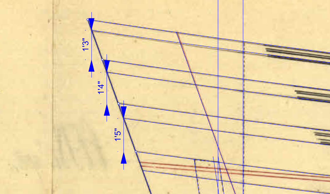
That's a simplification for the ease of understanding the logic behind the inclination given to the rails, but the actual measurements are taken from the top of one rail to another, so the width of each rail must be accounted for. What that means is that, in actuallity, that's how the different rails are set:
Now, with regards to the fore curves, I feel pretty stupid 🤣. Remember I was trying to give some inclination to some progression to describe them? And that I explained you how giving those inclinations change the curve given as a result? Yeah... Scrap all of that. I mean, the explanation is still valid, but that is not what was done to get the fore curves.
The Boudriot excerpt that @Waldemar sent here made me see it.
Jean Boudriot - Méthode par les triangles équilatéraux.pdf
The solution is pretty close to what is described for the "A" alternative for harmoniously dividing a lisse. And, again, it can be seen on the G1228 60 gun ship scaled up from Fyen plan, on yet another part of the plan that I had not shown you 😅. I mean, come on, had I shown you the entire plan from the start, I'm sure a more experienced member would've caught up to the solution at a glance and saved me A LOT of trial and error. The problem now is worked out, but just out of principle 😆, here it goes, the entire plan:
That's the section we'll look at to understand the fore curves:
An 45º arc (BC) is drawn from a radius AB, of any lenght. From the upper edge, C, of the arc, the perpendicular CD is drawn. CD is divided proportionally to the ship's frames, from midship to stem (1,2,3,4,5,6,7). The frame's spacing is projected onto the BC arc, and that results in the points 1b,2b,3b,4b,5b,6b,7b. These latter points are projected down, again, onto the DB line, and that will be the proportion applied to describe the fore gun deck and wales curves. It's a perfect match with the fore curves' proportion triangle:
And, most importantly, it's also a great match with Hvide Ørne's and Wildmanden's curves. The fore sheer is also a rotation of the fore wales, the same as aft.
WELCOME HVIDE ØRNE
Also, I'll officially include Hvide Ørne in the topic's title. When I started the topic, I was already developing Hvide Ørne's lines too, but I was less advanced with them and I wasn't sure I would be able to work out some quirks of its design (among them, the sheer plan curves), but that have now mostly been mostly figued out. Hvide Ørne is Wildmanden's bigger sister, done by Turesen just a year earlier than Wildmanden, and shares many the same design rules with it. While Wildmanden is more of a sloop, or a corvette, Hvide Ørne, that carried 30 guns (the quarterdeck guns included), was a proper frigate by the broad understanding of the time. It also shares the good looking lines of it's smaller sister. That's a very subjective claim to make, but I don't think you will find a prettier "true frigate":

And, of course, on this 24th of december, I wish you all a merry christmas,
-Arthur.
- Kenchington, Martes and druxey
-
3
-
On 12/18/2025 at 4:08 AM, TJM said:
Hi Arthur,
I am quite impressed - I have yet to sit down and actually understand how these constructions were made from mathematical principles, but would love to get into that some day.
I passed by the Krigsmuseeum the other day and tried to grab a few shots of Wildmanden - It is very dificult to photograph it, as the model is small, the prow is facing the frnt of the display case, and the case is very large, so it is hard to get a proper profile shot.
I am not sure these will really help you, but perhaps there is somthing to be seen on them still 🙂


TJM, thanks a lot!! Those are some very good photos, and references are never enough. I'm sure I'll put them to good use!
Trying to understand these plans is a fun puzzle, a little mind cracking sometimes, and a lot of trial and error goes. A good CAD software is a must.
Danish plans are pretty special, because they often explain and give measurements for much more than any other nation's. And well, being Danish yourself, you're in a great position to get into it.
Cheers!
-
1 hour ago, Waldemar said:
Arthur, many thanks again for your help in translating this excerpt from Fernandes' work. As I already wrote in the private message, it is now really clear and finally ready for further work. Well done
") .
.
As for your “Wildmanden” project, I won't bother you with source material anymore, but instead I highly recommend Jean Boudriot's particularly clear explanations of this particular design method (attached). I would even say that reading this excerpt, taken from his larger publication Les vaisseaux de 50 & 64 canons, is an absolute must.
Jean Boudriot - Méthode par les triangles équilatéraux.pdf 8.98 MB · 1 download
I'm happy to be able to help. Translating that was super interesting too so, it's a win win. 🙂
And, Waldemar, thanks a lot for the excerpt, it sure looks very helpful! I'll read it before I make more progress with my Wildmanden endeavour for sure. Appreciate it!
-
7 hours ago, Kenchington said:
Don't feel bad! English and Nautical English can feel like different languages sometimes. Then there's the English of Shakespeare and the King James bible (neither much older than the Livro) which would be misunderstood today, were it not that so many of us were exposed to those as children. I doubt that Portuguese is any simpler!
Trevor
It's for sure one cool riddle to interpret those old texts though!
4 hours ago, Martes said:There is a contemporary plan for the frigate La Licorne
https://www.rmg.co.uk/collections/objects/rmgc-object-82907
but you'd note that both her and Belle-Poule's reconstructed wales include a step above the wale, on the gundeck level, just like on the model and plans for Wildmanden. A that's what the Danish got rid of towards the end of the century, making the ships' sides totally smooth.
Ohhh I see. It adds up! I didn't know the Danish eventually smoothed it all out.
3 hours ago, druxey said:Is part of the deviation issues that you illustrate due to distortion of the original plan due to paper expansion/contraction or in the reproduction process?
Druxey, I don't think it's a matter of age related or even scanning issues for these specific Wildmanden/Hvide Ørne plans. The reason being is that the straight lines are very straight on them and all the perpendiculars are very close to perfect 90º.
Drafting those curves precisely by hand and eye, however, isn't easy. What that would entail is applying a 9 number progression to a space of, at most, 3'2" ÷ 48 (which, I take it, is probably the scale the plans are on). After getting the correct proportions for said lenght, the draftsman would, most likely, draw provisory line from where the curve starts amidships parallel to the waterline, and use this line as reference to set, lets say, the wale curve. For that, he would measure the space from the beggining of the progression to the first division. Then, he would take the measured distance and apply it from the reference line up on the C frame (the first frame that has a perpendicular on the sheer plan fore of the midship frame), and so on, as many times as there are perpendiculars to the stem. Maybe he simplifies it, and he doesn't apply the respective heights on every perpendicular. In conclusion, there are many opportunities for small errors to be introduced.
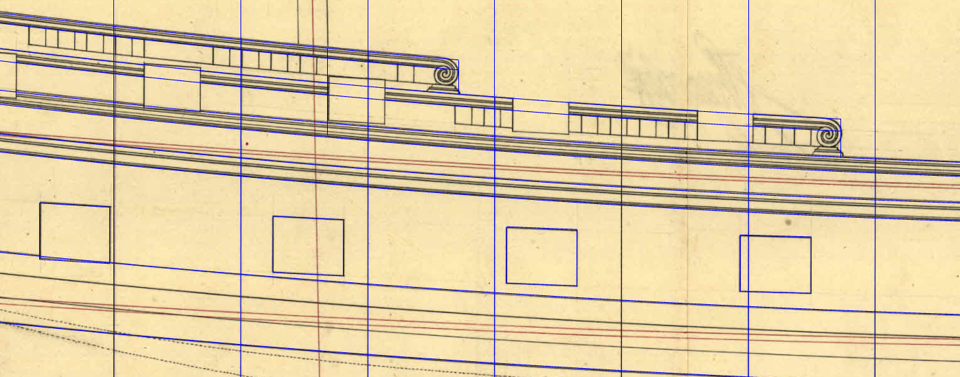
Thing is, I was about to write a whole segment on why if my progressions were wrong, I'd expect to see the error on the wales of Hvide Ørne, not on its sheer, then I'd explain why it isn't possible to give more inclination to the sheer's progression to get it right with the plans. But, before all that, I decided to take one good shower. *Eureka moment*. The explanation is simple. The sheer does not get a progression of its own. Instead, Turesen, at least for Hvide Ørne, did that entire process to get the curvature of the wales, but, instead of doing it all again for the the sheer, he simply copied the wales' curvature and rotated it two inches down, and there you have it: the sheer line. It matches perfectly. Let's zoom in on the problem area again:
In blue, the previous solution; in red, the new finding.
Notice how my line is slightly above the plan's line for the wales. Notice how that very same slight difference is now seen on the sheer with the red line; and notice how the blue line is not that slightly above the sheer. I think it's a hit.
It has be said that the rotation solution isn't random either, the same is observed when drawing Hvide Ørne's forecastle and quarterdeck rails.
Now I have to test out what that means to the aft sheer line, and how that finding can be applied to Wildmanden too.
This all also goes to show how careful Turesen was with his drawings, the man knew consistency, that much can be said.
-Arthur
-
On 11/25/2025 at 12:20 AM, Kenchington said:
I used to think that I understood pre-modern ship-design methods.
And now you show me how wrong I was!
Time to go back to the elementary class and start over.
Trevor
Trevor, this week I learned I don't even know my on portuguese language when translating Livro de Traças de Carpintaria for Waldemar 🤣
On 11/25/2025 at 8:31 AM, Waldemar said:I will start from the beginning, as it may be useful to others as well.
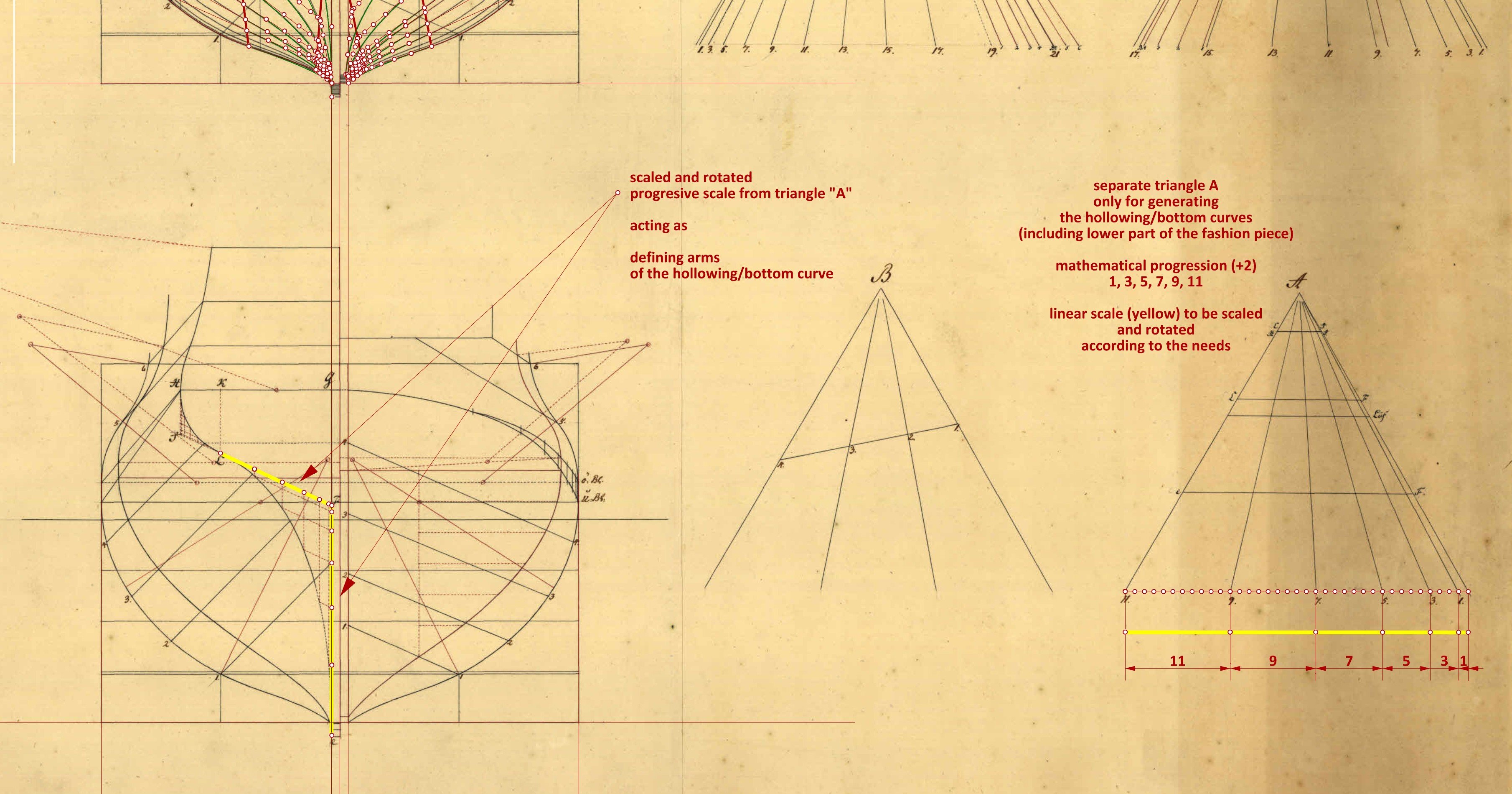
To generate hollowing/bottom curves, Turesen constructed a separate progressive scale, specifically using a mathematical progression (in this case +2). Based on this, he built triangle ‘A’ (on the right of the below reproduction), which triangle was particularly useful in manual drawing for quickly scaling this linear scale.
Fortunately, in a separate diagram (on the left of the below reproduction), Turesen has also shown how he used this progressive scale to generate the hollowing/bottom curve for the fashion piece. All that is needed is to adjust the progressive scale to both defining arms of the curve by scaling and rotating it appropriately, then, starting from the points on both scales, draw two sets of lines parallel to both arms, and finally connect the points where these lines intersect. And, voilà, the hollowing/bottom curve is ready.
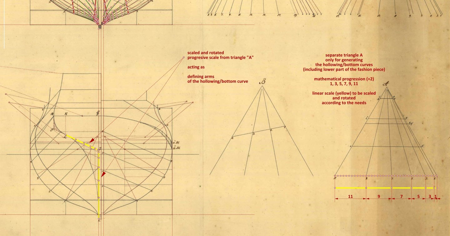
In order to maintain geometric consistency and, consequently, to obtain harmonious, smooth shapes, the same procedure and the same progressive scale should be applied to all other frames. In addition, the vertices and terminating ends of both arms of the hollowing/bottom curves for all frames must necessarily lie on a curve with a harmoniously smooth course, preferably on a straight line in the ‘body plan’ projection.
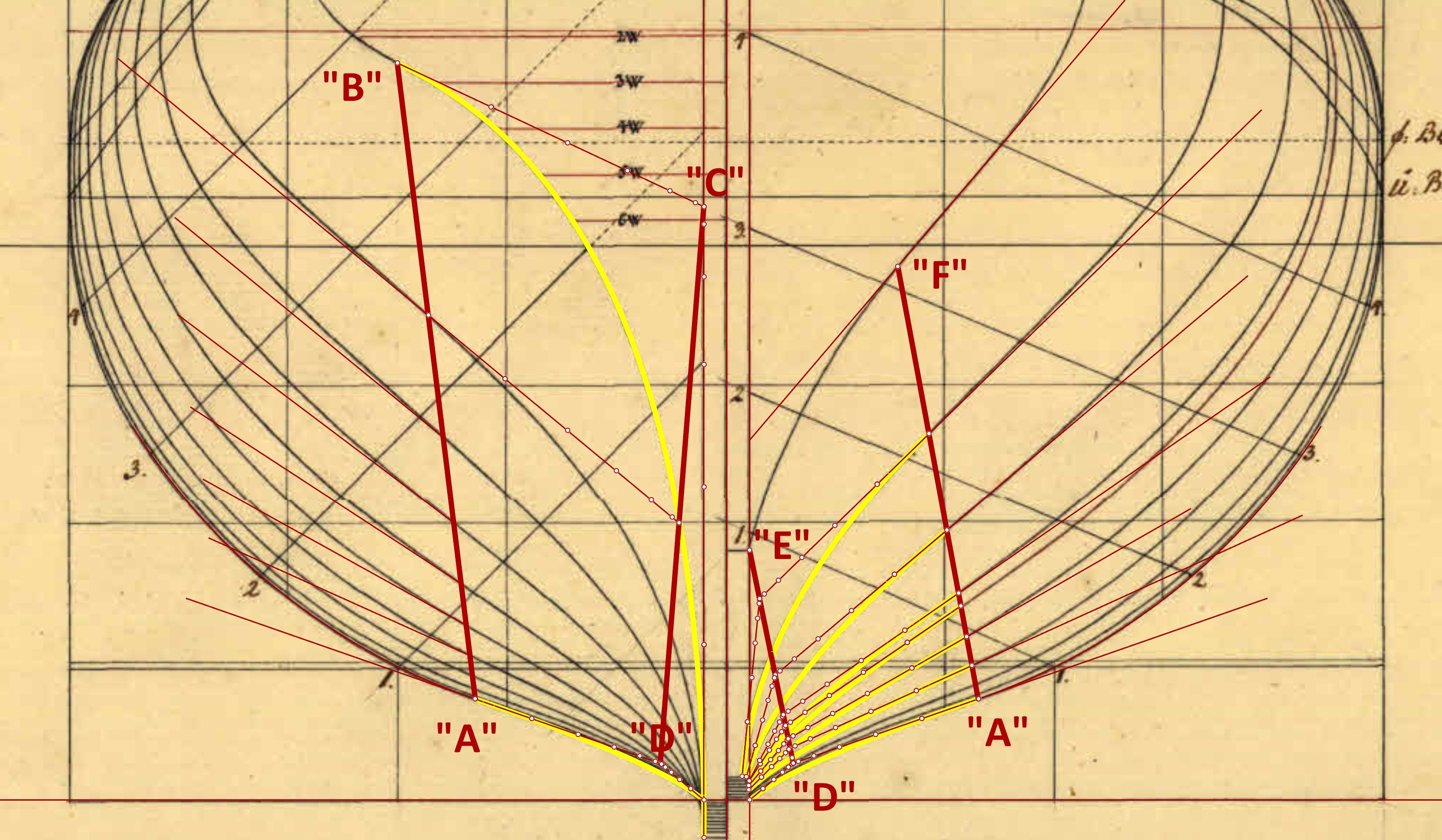
— The location of point ‘B’ is the spot where the curve of the fashion piece changes from convex to concave (which may be also said of the start of the hollowing/bottom curves for all other frames), and it is even marked by Turesen himself on his diagram as point ‘L’ (see above).
— Point ‘C’ is the apex of both arms defining the hollowing/bottom curve of the fashion piece.
— Points ‘A’ and ‘D’ (the latter is the apex of both arms defining the hollowing/bottom curve) were found in such a way that they meet the following conditions: the course of the hollowing/ bottom curve for the master frame is consistent with the course of this curve on the original plan, and, the resulting lines ‘AB’ and ‘DC’ must generate the correct shape (i.e. consistent with the original drawing) of the hollowing/bottom curves for all other frames. Finding these points “A” and ‘D’ is a fairly typical iterative operation based on trial and error fitting.
— Point ‘E’ is the spot where the first bend connects to the keel assembly. In a sense, the geometric nature of this point is similar to point ‘C’.
— Point ‘F’ is again an empirically found spot where the frame contour switches from convex (or straight) to concave form. As with the aft part of the hull, the resulting lines ‘DE’ and ‘AF’ must meet the conditions described above for lines “AB” and ‘DC’, i.e. they must correctly define the coordinates for the arms of the hollowing/bottom curves of all frames.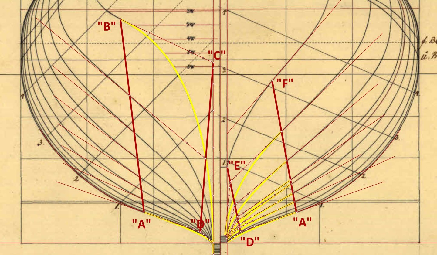
Makes perfect sense now, Waldemar! Thanks a lot for taking the time to figure it out and to explain it!
On 11/25/2025 at 10:25 AM, Martes said:A bit of both, I suppose. But it is definitely more expensive and requires more time, effort and quality control to produce, install and post-process uneven planks, thinner at one side and thicker at the other, that form the blended wale and have to be precisely touching one another. The British adopted this practice only in the wake of the captured Danish fleet, as they were really impressed by the Danish workmanship.
That's interesting though, wouldn't they be already familiar with the Danish type fo wale from French ships? If the Boudriot monographs are to be believed, the french had the same blended wales as the Danish did since somewhat early on. That's not what the captured plans for Belle Poule, for instance, suggest (Belle Poule (1780) | Royal Museums Greenwich). But Boudriot's monograph do give Belle Poule blended wales:
 On 11/25/2025 at 10:25 AM, Martes said:
Note that in itself this is a case of reverse-engineering of a French design that passed through British hands.
Fascinating stuff!
- GrandpaPhil, Waldemar and Martes
-
3
-
Since the last post I made, I've been dwelling with the wale/deck/sheer curvatures. I'm convinced Turesen applied an angle to the progression used to draw them fore.
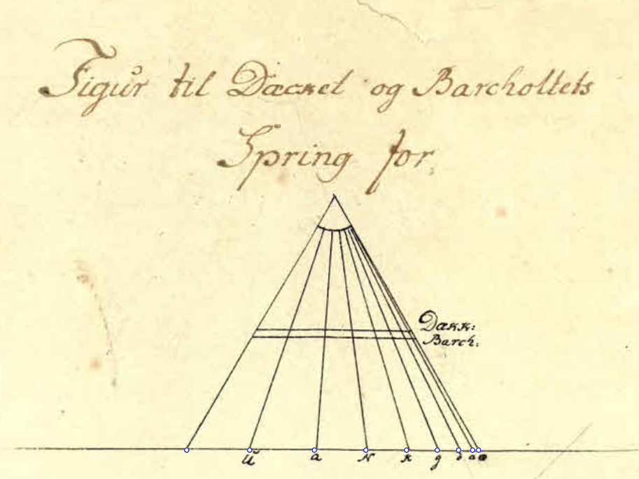
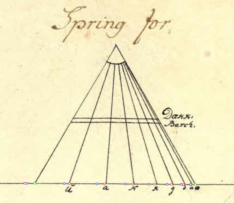
Lets first get back to the G1228 60 gun ship scaled up from Fyen (1749) that I showed you last time. The previous post I explained how a 1,2,3,4... progression was used to define these curvatures aft:
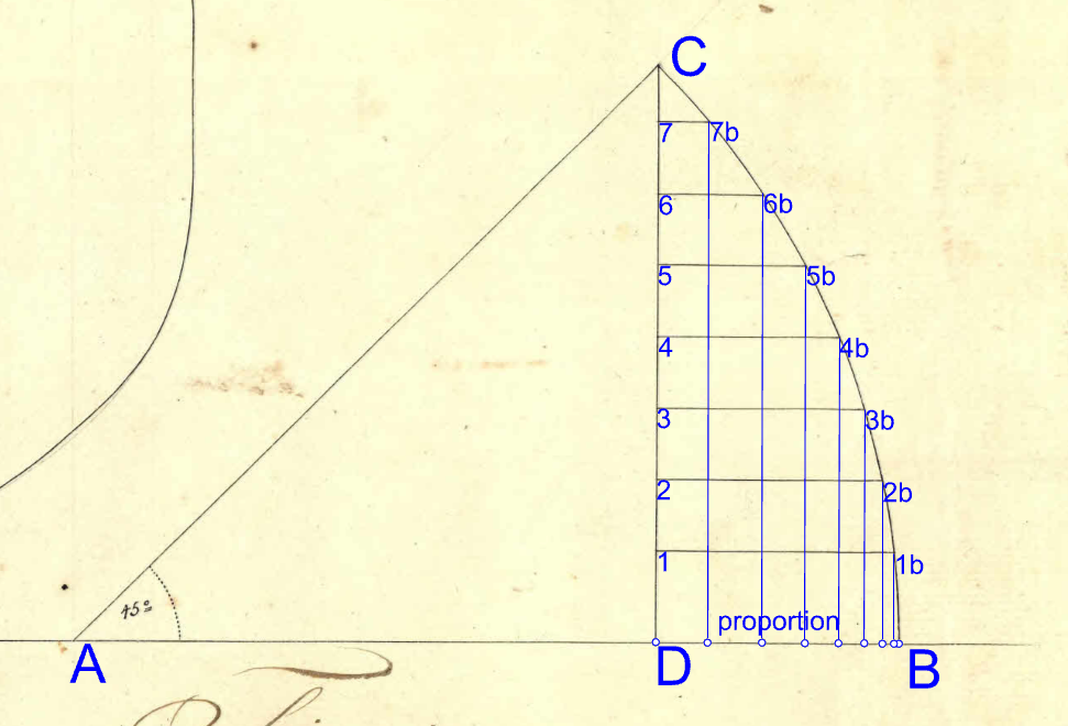
What I didn't show you, however, is that the plan presents a different triangle for setting the same curvatures fore:
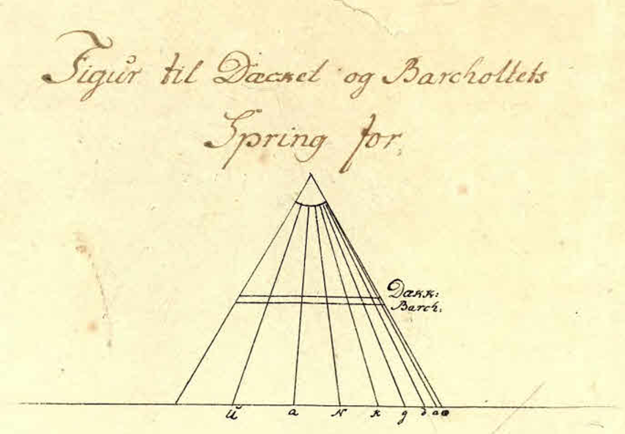
At first, I thought this was another 1,2,3,4... progression, thus not different from what is seen for the deck aft. But, it is not. You see, what its spacing suggests is that it results from an angled line applied to a 1,2,3,4... progression. To make what I mean clearer:
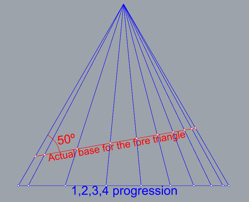
That's how it looks when both the 1,2,3,4... progression (in blue) and the 50º progression (in red) are scaled to the lenght of the base of the fore triangle:
(in green, where there are both blue and red points)
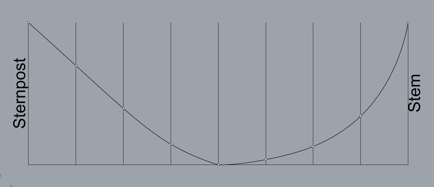
This is not the same as is shown for the wales (barckholtets) aft, it's actually the opposite. The 50º angle gives the wales aft a more uniform incline, it makes them more akeen to a straight line, if you will; while the curves fore start off gentler and get steeper towards the stem. An exaggerated representation:
As for the G1228 60 gun ship, it is possible that we have more of a 48º angle to the progression instead of a flat 50º one, but that specific plan was not neatly drawn at all, so, hard to know. The important thing to be noted here though is that despite, in practice, the difference between a deck drawn by a 1,2,3,4... at 60º (so, parallel to the base of the triangle) and one drawn by a 1,2,3,4... at 50º being very slight, for some reason, that differentiation in methods for the fore and aft parts was done.
Grant it, that still is just one plan, it would be quite the bit of anecdotical evidence to be considered for Wildmanden. Well, it would be, if the same wasn't observed not only on Wildmanden's plans, but on Hvide Ørne's (1753), and on Fredericus Quintus's (1753) too. They all have a curves that get steeper towards the stem fore and straighter ones aft, as to suggest the same idea present on G1228 is present on these Turesen designs.
So, I got to more testing on Hvide Ørne and Wildmanden, I tested all kinds of progressions, and two other methods too: projecting the a section of a circle onto the frames and getting the heights of the wale/deck/sheer at each frame that way (a method I've seen by english shipwrights), and drawing the curves by a circle that has it's center 90º above where the curve starts amidships. Those alternative techniques yielded no better results than what I got from triangular progressions. My unorganized progression tests:
What I landed on for Hvide Ørne (1753) was a 1,3,5,7... 60º progression for all aft curves, starting off on the fore midship perpendicular; and, a 1,3,5,7... 50º progression for all fore curves, starting off, again, on the fore midship perpendicular:
Some close ups of how it is looking. I'm quite happy with all the aft curves, and all the fore curves with the exception of the sheer, where some deviation that I feel like could be something that I'm still missing is seen:
I tried applying the same progressions for Wildmanden, again, with satisfactory results for the aft. But a similar problem presents itself fore, but the other way around for Wildmanden. While my sheer line agrees with the drawing, the deck/gunports and wale curves show a slight deviation. The recurring issue in both drawings being that the sheer doesn't seem coherent with the other fore curves. On Wildmanden:
I could fix Wildmanden's curves that aren't the sheer by using 1,2,3,4... 50º instead of 1,3,5,7.... 50º, but if I were to apply the same to the sheer, it then would have a deviation from the plans. For Hvide Ørne (1753), however, the 1,3,5,7.... 50º is the best solution I found for all curves.
It might be just a matter of imprecision of the hand drawn plans, I'm open to suggestions though. If I find something better, I'll let you know, if not, we'll move on to explaining the stem/sternpost and the location of the quarter frames and transom diagonal.
And, by the way, Hvide Ørne has some pretty interesting differences for how it's body plan is done, should I make the topic a two in one package by exploring both Wildmanden's and Hvide Ørne's lines?
Cheers!
Arthur.
-
-
13 hours ago, Martes said:
Well, painting of ships was always somewhat fluid, subject to paint availability and all, and not necessarily coinciding with the run of the planking at all.
From construction point of view, at least in 1807 it was observed by the British (Naval Chronicle article about the captured ships) that on the Danish ships the wales are blended into the planking, thus preventing accumulation of filth.
The decoration plans follow the French practice, that usually shows the uppermost and the lowest planks of the wales, creating an illusion of having two. It's purely a drawing convention, however.
I missed answering your post previously, Martes. Apologies. But yeah, it makes perfect sense to that the paintings shouldn't really be trusted in the matter. And that 1807 passage is gold! I mean, I could never imagine that is the advantage behind one type of wale over another. I wonder what's the plus of not having the wales blended into the planking. Maybe easier construction? As the thinner planks would be easier to bend.
-
4 hours ago, Waldemar said:
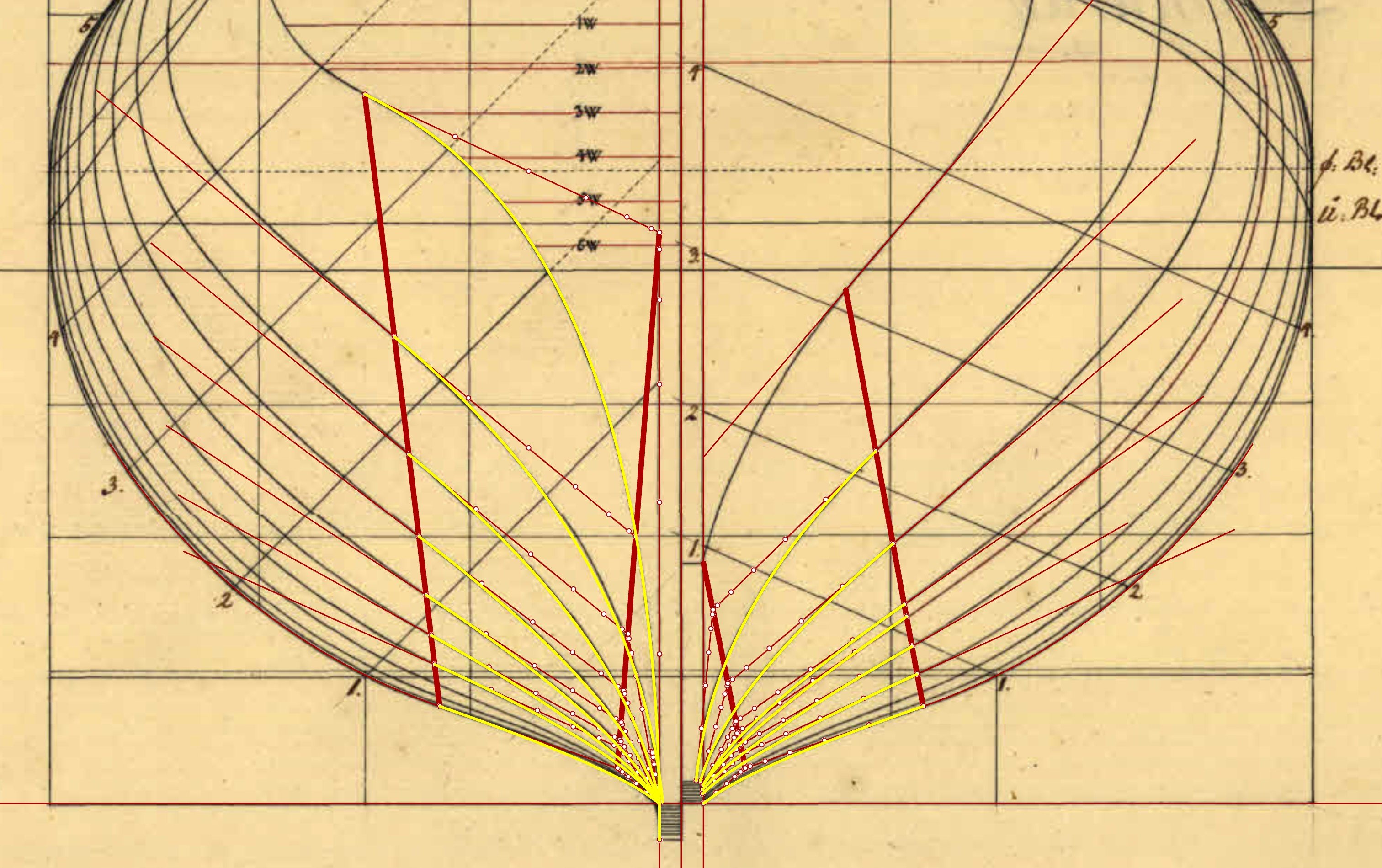
I think I've found a way to generate hollowing/bottom curves that works for Wildmanden. Take a look at the diagram. The yellow lines are hollowing/bottom curves generated in a geometrically consistent manner, according to the progressive scale for the fashion piece from Turesen's plan. The thick red lines are auxiliary construction lines defining these curves.
If you are interested, I will be happy to explain the details that may not be clear from the diagram alone.
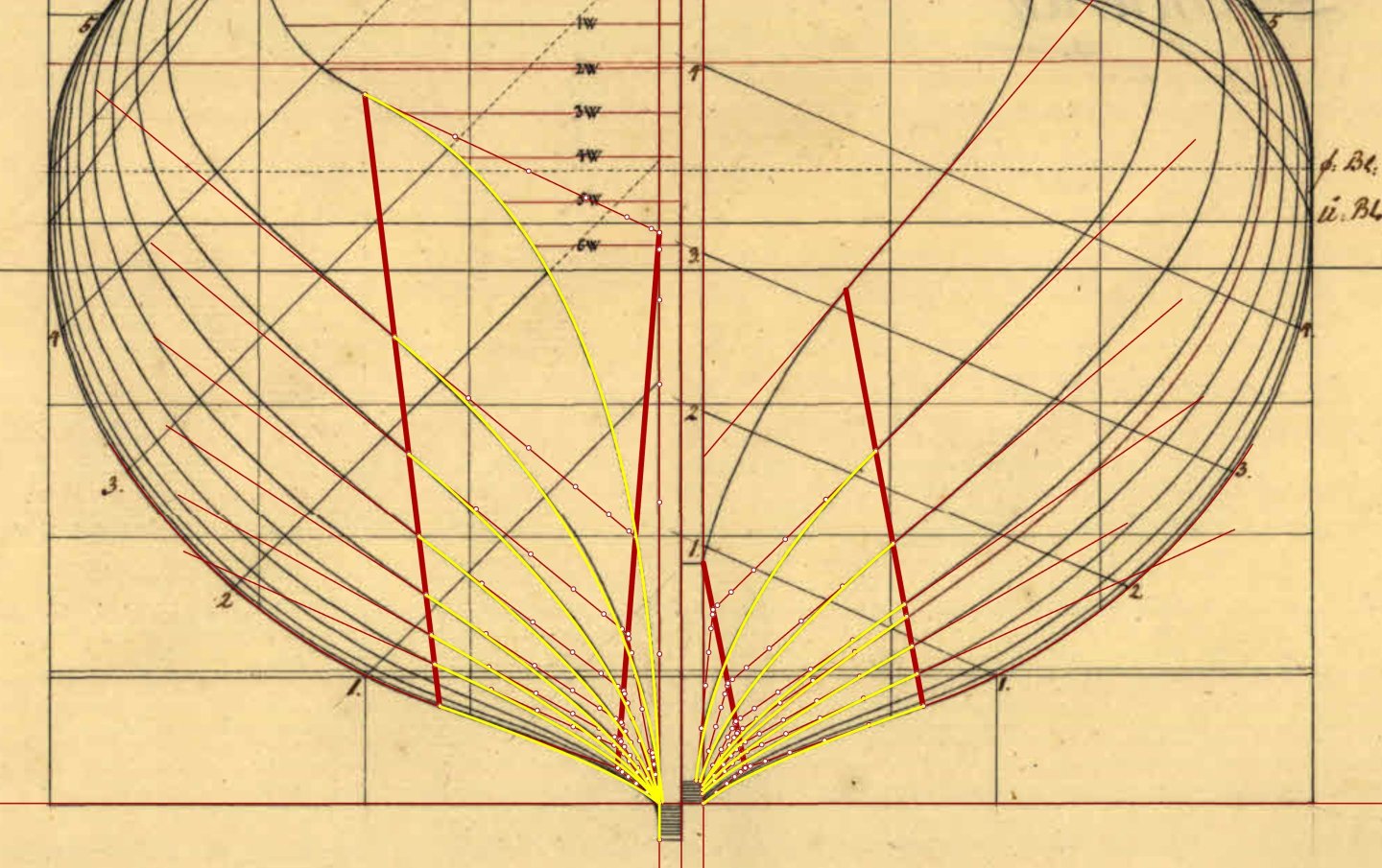
That is very neat and clever, Waldemar! Those were the lines I couldn't wrap my head around. You've arrived at an explanation that produces a very spot on result and that makes sense. The one thing I didn't understand is how you came up with the position of the thick auxiliary construction lines. Could you elucidate it? Thanks a lot!!
-
Ok, ok, ok
The first post has stirred the pot much more than I would've imagined. That's awesome! Happy to see so many of you guys engajed on this project.
The context given by @TJM (thanks for it by the way!) is a perfect introduction for the next part of the reconstruction, as will be clear. Let's get to it:
GUNDECK, SHEER LINE AND WALES
As already noted, Wildmanden, was designed leveled to the waterline rather than the base of the keel. That's a method that is never seen on English plans of the period, that isn't the most frequent with French ones either, but that was common in Nordic practice.
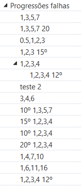
What it means for this chapter of the Wildmanden reconstruction is that all measurements make most sense when taken not from the rabbet and up the perpendicular, but rather from the waterline, or, better yet, from the line that is paralel to the waterline that starts on the lowest edge of the keel aft, henceforth I will be calling baseline. From the baseline up the perpendiculars, the heights for the ends of the curves that form the lower and upper limits of the gunports, the wales, the sheer are the rounder, and I mean, so neatly round it can't be a coincidence, and I'm convinced I got the heights chosen by Turesen right. Let's see:


The lower side of the gundeck is offset 1'7" relative to the lower limit of the gunports. The upper and lower gunport limits, as well as the deck, ends at the same height aft relative to the baseline as fore. The sheer line drops 1'6" in height amidships, then rises 3'0" aft. The upper edge of the wales ends aft 2'0" above the lower side of the gundeck. The freeboard amidship is given by Turesen as 5'6". I think that shows the point, except for the lower side of the gundeck (which makes sense), all dimensions can be explained with a 0.5 feet precision. Interestingly, a proportion can also be observed when comparing Wildmanden to the unbuilt A1246c brig. On both cases the deck/gunports line rise fore and aft 1/3rd of the freeboard.
Now, to the more interesting part of today's post, how these curves are formed.
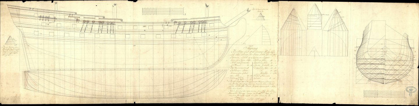
The shipbuilding manuals of the period I've read so far really overlook the description of these curves. Not only the shipbuilding manuals, I was overlooking the lines myself, I had a sort of working solution, but without a basis in literature or something else for it. That's when I stumbled upon a specific plan, G1228 (which, by the way, lovely looking ship, I'd love to reconstruct it in the future too). That plan is for 60 gun ships built based on Fyen (1749), that TJM taught us about. On G1228, the method for forming the deck and sheer lines is represented:

The plan, is unsigned and from 1758, by then Turesen had died. However, the plan also informs that the Storman, the Island, and the Seyeren were built to its lines, ships that went through Turesen's hands. The previous plans for the type available on the archives are all from 1750, before any of the three ships was finished (and maybe even started, I'd have to check). The older plans show a different deck layout, and don't demonstrate its forming. The fact is, even if Turesen wasn't responsible for showcasing this progression based method for drawing the decks, he certainly was familiar with it, and I think, that is the practice behind Wildmanden's lines.
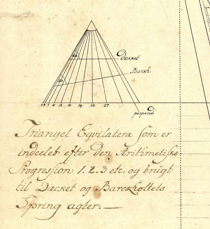
It works quite simply: a progression is made by setting whatever length, let's say 1 inch; from the end of this first length, 2 more inches are set off; then 3, and so forth. As many lenghts are set as there are perpendiculars from the master frame to the stem or sternpost. Connect it all to the apex of an equilateral triangle, as seen above. That forms a ratio that is applied to the amount the deck, sheer, wales rise. In Wildmanden's case, for example, the deck rises 22 inches: 15'7" is its height from the baseline amidships, and 17'5" on both extremes. That ratio determines how much the curve rises on each frame. I hope that makes sense to everybody reading.
But, the only way to know if that was indeed what was done on our ship, is of course, to try it out. And that I did, but not only on Wildmanden, but more importantly, on the unbuilt A1246c brig. Any variation of the method I tried was kinda good enough for Wildmanden, since the curves on it don't rise all that much when in relation to the frigate's lenght. On A1246c, on the other hand, the sheer skyrockets (technical term 🤣) up aft. So, I tried using a 1,3,5,7... progression, I tried applying the sheer rise to the equilateral triangle on different angles (as is seen for the sheer line of the 60 gunners above), I tested different progressions fore and aft, I tested the progressions on the wales, and so on. The conclusion is that the 1,2,3,4 explained well enough, actually, more often than not, explained the best, all the different curves. 1,2,3,4 progression applied on A1246c:
Pretty good, right? There is that principle where the simplest explanation is the most likely, I think it applies well here. No need to go extra with it when 1,2,3,4 is enough.
That's how it looks on Wildmanden:
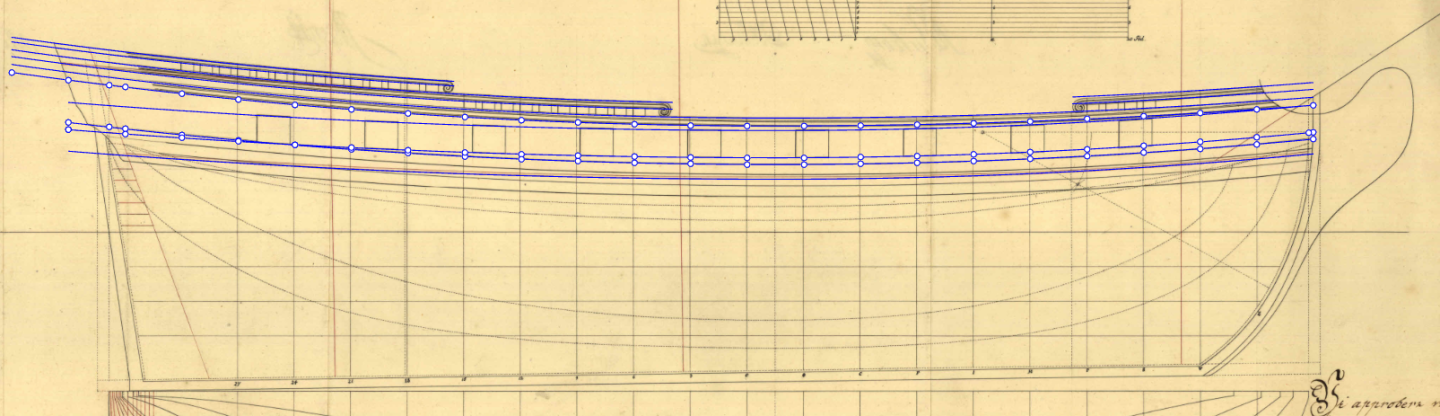
There is one spot where my curves don't line up so neatly though, the fore part of the sheer line and its parallel rails:

I could have the sheer's curvature align better with the plans by changing my method up, but that feels criminal. I mean, what that would imply is that Turesen used one same method for the wales, for the deck, for the gunports, for the aft sheer, but for whatever reason he decided to mix it up to get a very slightly different result on the fore sheer. Also, the upper forecastle rail seems like it should be half an inch narrower. Which, also, I find unreasonable. The correspondent quarterdeck rail is 6 inches wide, what's the point of making the forecastle half an inch narrower? What seems to be at play here are some more sloppily drawn curves rather than an intentional variation of technique.
What do you guys think?
Now, time to translate the Livro de Traças de Carpintaria for Waldemar! 😁
Cheers!
-
1 hour ago, Waldemar said:
This must be the outline of the fore quarter frame, which has special significance in the design. The set is completed by the aft quarter frame, but this almost coincides with one of the regular bends and has not been drawn separately.
Correct! On A1226e you can see it separately. The aftside should have a quarter frame too, but it's too close to one of the actual frames, hence why I think it was not represented.
-
6 hours ago, TJM said:
If you are looking for information on him, I can paraphrase what 'Danske Orlogsskibe 1690-1860' has to say?
Yes, please, @TJM! I found it pretty difficult to find information about Danish shipbuilding online, and well, it doesn't help that I don't speak Danish, so that'd be awesome.
6 hours ago, TJM said:Do you have all the drawings of Wildmanden from the archive?
I do! But thanks a lot, regardless! I might make contact with the people who run the archives though to see if I can get hold of some of the Wildmanden drawings that aren't available on the website. I suspect some alterations were made to the sheer plan after A1226c (the plan I posted above) were made, as the sheer line appears taller aft and the keel and stem look thicker on the later interior arrangment plan (A1226b)
6 hours ago, TJM said:Regarding the wales, I think you have it right. The drawing clearly shows the upper edge, just below the gun-ports. The middle frames for (almost?) all Danish ships after around 1730 does not show the thin double wales of the previous century, but rather these thicker ones, or even as this one just thicker planks that get progressively smaller further towards the keel.
However it is puzzling, as the contemporary paintings often still show two thin lines for wales all the way up to Gerner's time in the 1770's! Perhaps they were just painted this way at this point in time?
Do you think it could be a difference between warship and merchant ship practice? And so painters would eventually get it wrong? The models seem to agree with what we see on the plans. Take a look at this illustration, the ships have their wales outlined with black lines, but the wales themselves are wooden in color:
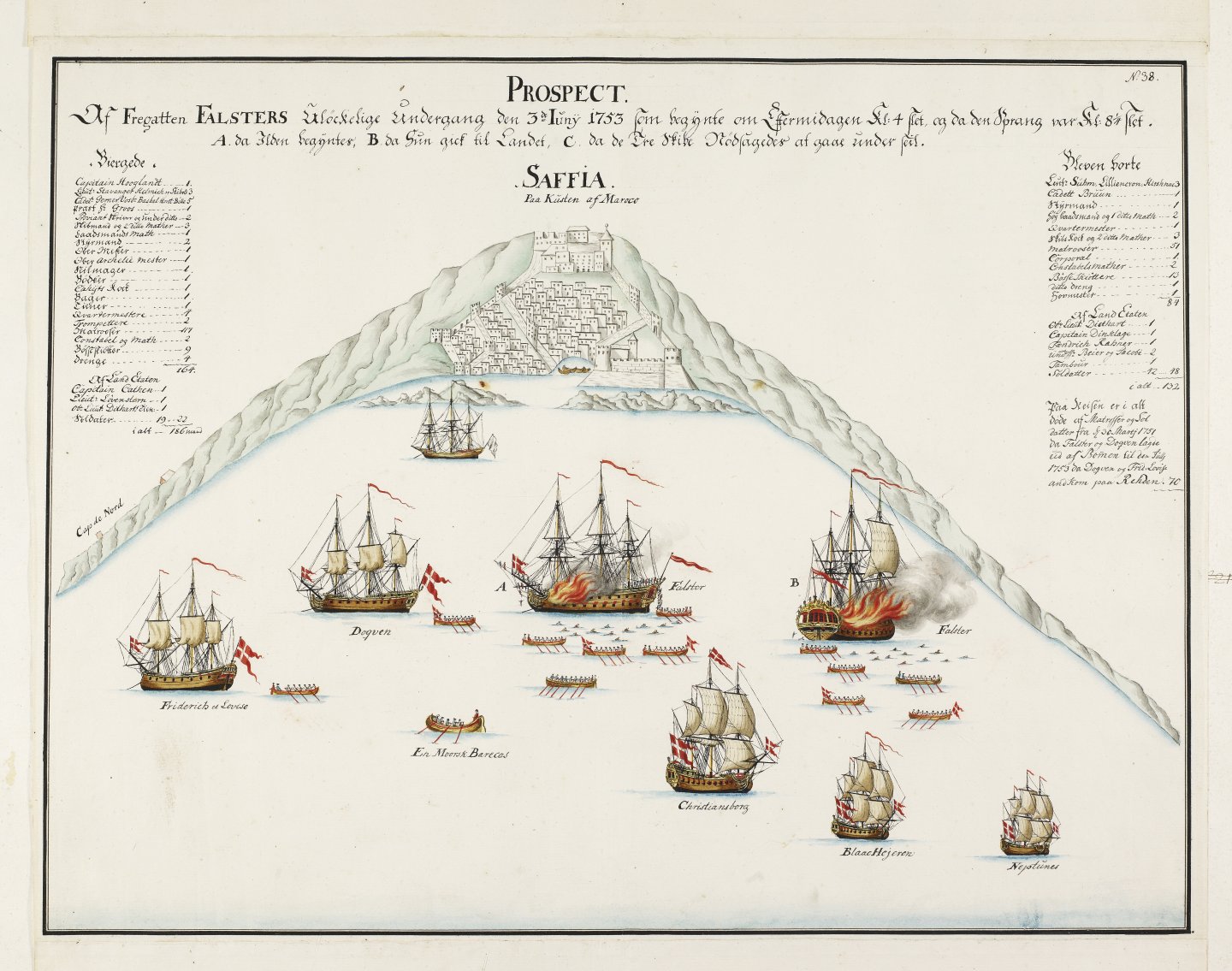
The image deviates from the gradually diminishing wales we see on the plans, yet, it suggests that what is seen on other illustrations isn't a matter of how the wales were painted.
6 hours ago, TJM said:Also, are you 3D modelling the ship, or are you preparing to make a wooden model as well?
Eventually 😁. But I just graduated, and I'm studying to get a well paying job, so I wanna get my own money sorted before I get to wood and sawdust. I wanna make her real nice, that takes money though. Meanwhile, I have a terribly designed Bluenose kit that I'm slowly messing with.
3 hours ago, Waldemar said:I wholeheartedly wish you success with this project, but I must honestly warn you that it is a design based on the (double) parabolic variant of the Northern design method (incidentally, the same method was employed by Joshua Humphreys to design the famous American frigates).
Waldemar, that's why it will be awesome to have you following along this reconstruction! Parabolic variant of the Northern design? I have no idea how that method works, would love to learn about it though.
However, Turesen gives instructions for the midship frame on A1226e it is made by only two arcs below the breadthline, a smaller one tangent to the breadth, and a larger one, that starts tangent to the smaller one and intersects the end of the floor timber. Above the breadth, two more arcs, again, a smaller one tangent to the breadth, and a larger one, tangent to the smaller one that ends on a point at the sheer's height that has 4/5th of the midship's frame half breadth. All radii are some proportion of the breadth. That's what Turesen describes:
That leaves the hollowing curve unexplained, hence the other topic I started. I haven't yet looked into what you pointed me towards though, the Boudriot's articles.
The reduction of the frames is done by the french equilateral triangle method, aided by a Luff frame, which I think I've seen in english as a quarter lenght frame, something of the sort. It's an intermediary frame (in red on the figure above) that defines the angle by which the ribbands are applied on the equilateral triangle.
4 hours ago, Waldemar said:And I won't even ask if you already have working CAD software (and which one specifically), which is absolutely essential for such projects, because I'm afraid of the answer
. A regular vector graphics software for creating usual illustrations is not suitable. It's not that CAD software replaces knowledge of geometry, because it doesn't, but it offers tools that allow you to use those skills efficiently.
I'm using Rhino, Waldemar 😁 I tried blender out, it was no good for this purpose.
4 hours ago, Waldemar said:And, by the way, may I ask about your native language?
You sure may! It's portuguese. I'm an across the ponder, from Brazil. If you need some help with those 16th century portuguese manuals, I'm more than happy to help out!
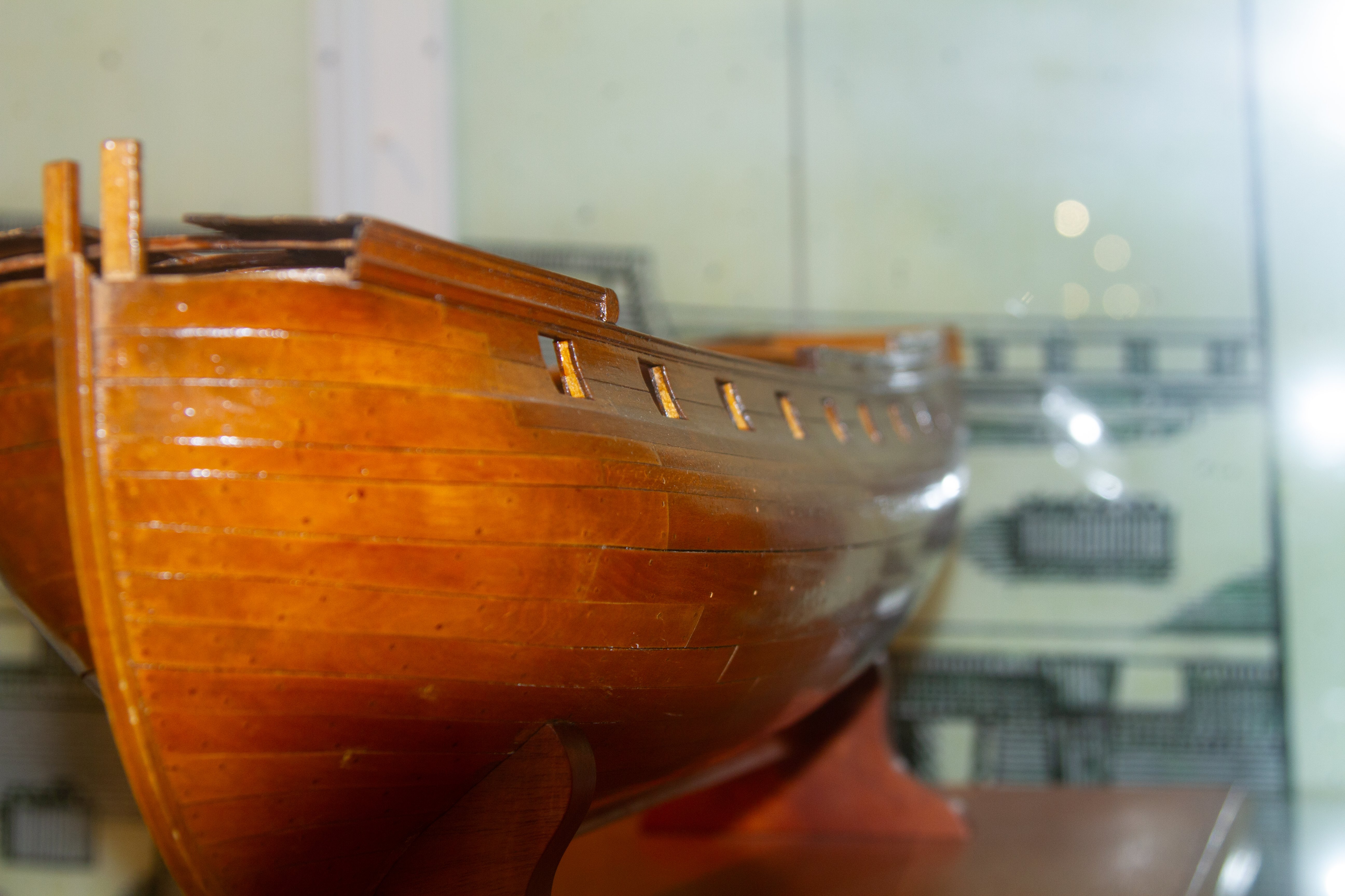
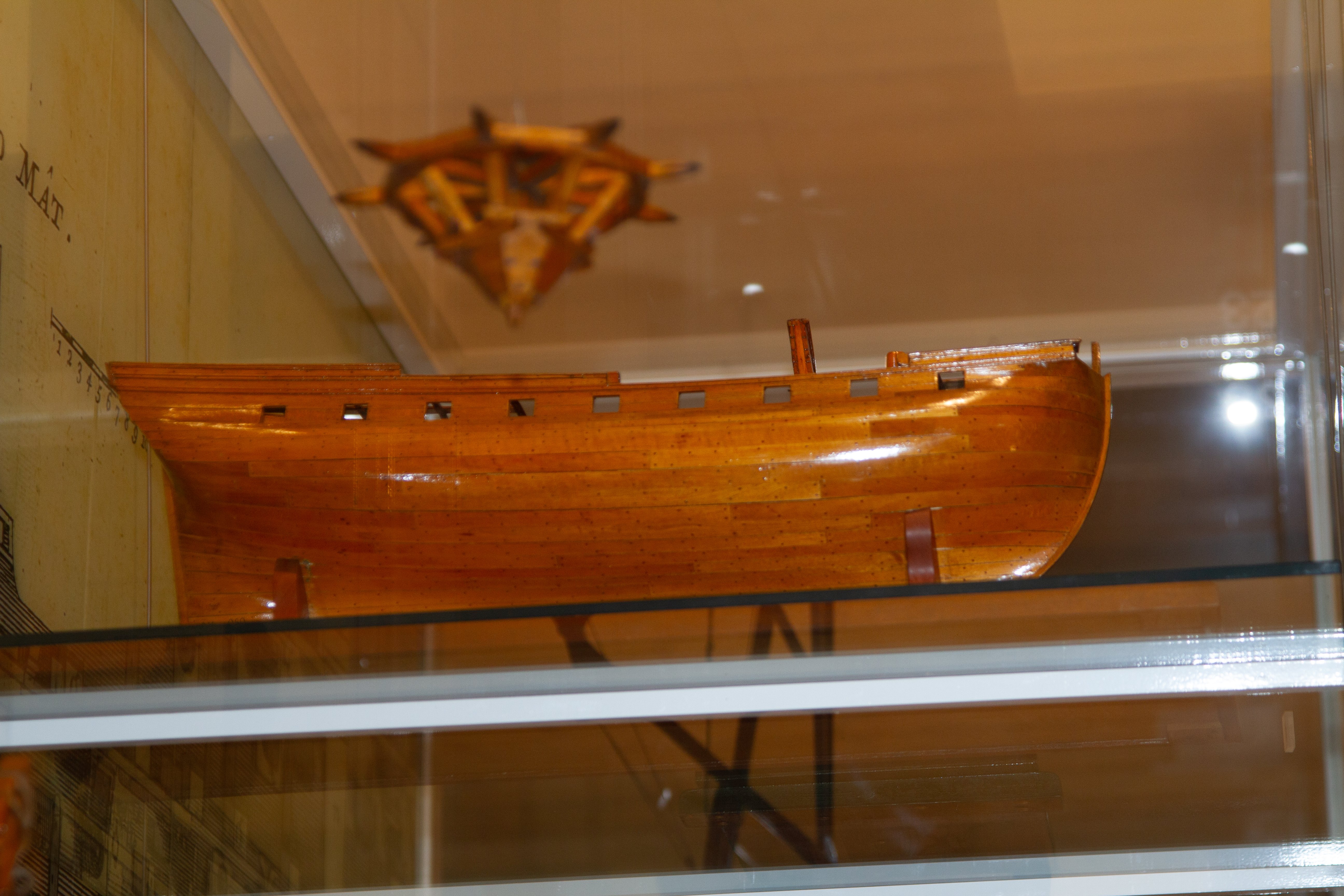
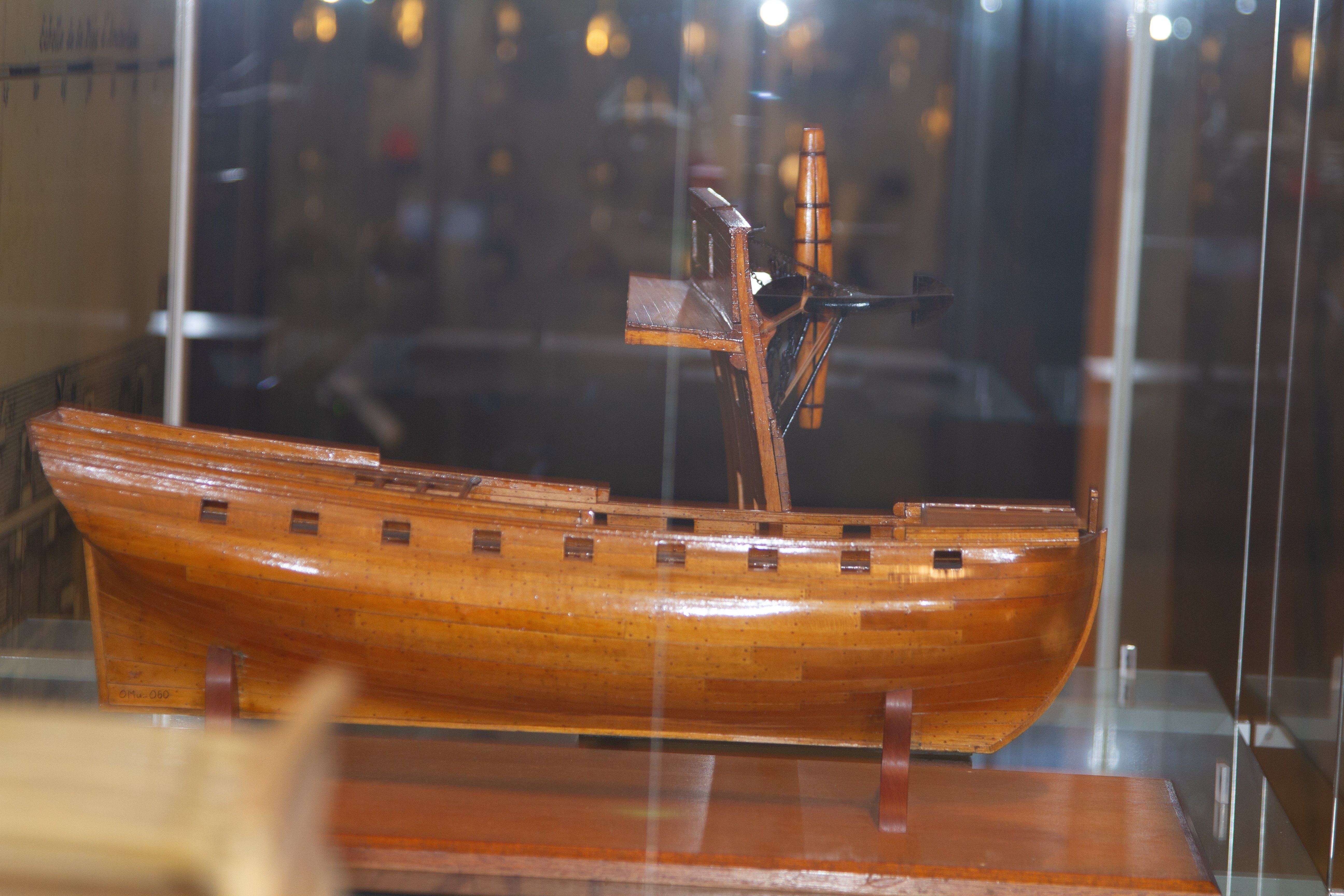
3 hours ago, Beckmann said:I looked up my photo archive, here are some more photos of the fregat Wildmanden.
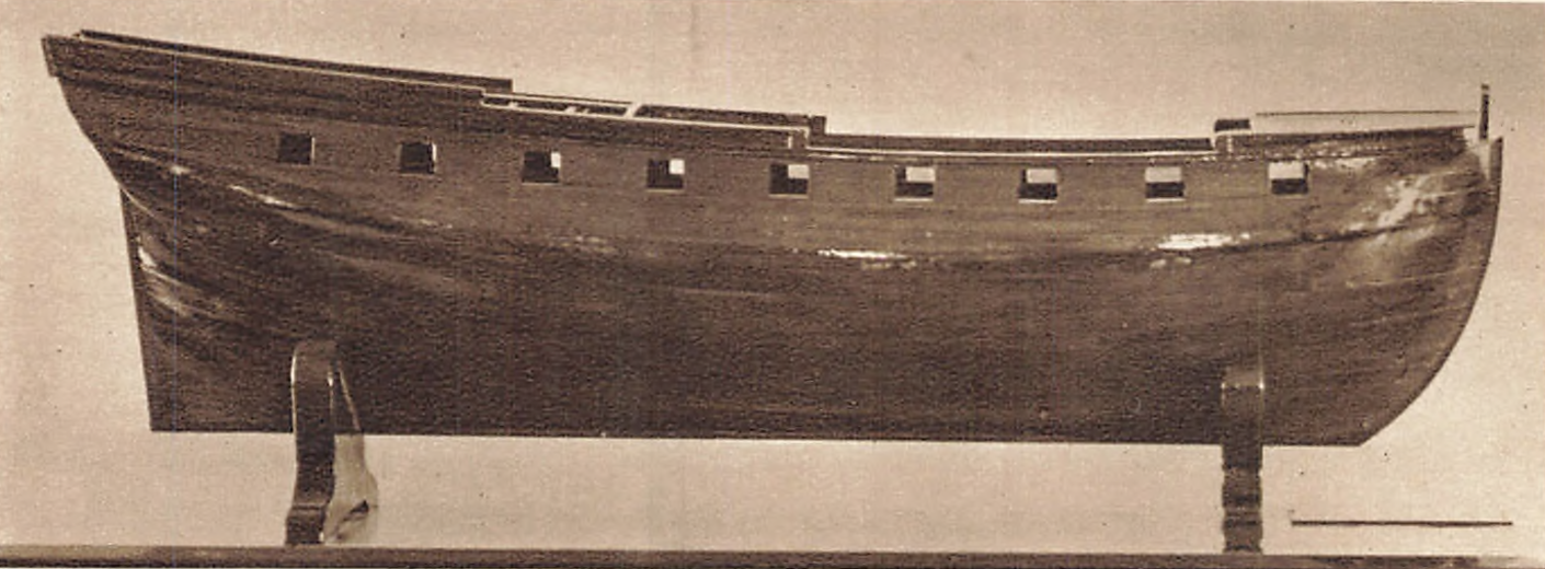
Matthias, thank you very much! Those are great. They confirm my suspicion about where the wale line is on the model. There are some very weird wide planks on it though. Do you guys think that could be a correct representation of how the real ship was planked? Surely not, right?
1 hour ago, ccoyle said:The name is probably derived from the word Wildman or Vildman, the mythical "man of the woods" that is a common heraldic figure in Germany and Scandinavia. Here's one from Laponia.
That is awesome to know!!
- TJM and GrandpaPhil
-
2
-
5 hours ago, Y.T. said:
I also enjoy how the planking was done at the bow. Looks like planks were cut out curved off the sheets of wood rather than force bending the straight ones. The planks lay out so naturally and almost perfectly parallel to waterline even at the bow.
There are some outstanding contemporary models for sure, not surprisingly, when you consider some of them were made for the royal, some were made on comission by important people, some were prized gifts. @Beckmann a couple days ago linked me to an article of his that showcase some of the finest Danish models: https://www.arbeitskreis-historischer-schiffbau.de/mitglieder/ontour/schiffsmodelle-in-daenischen-museen/ .I take it you're probably already familiar with the models on RMG's website, besides that, I'd suggest you check out the Roger's Collection, the collection of the Musée National de la Marine, the Museo Naval de Madrid has a lot of their models on their instagram page, be aware though, that is one rabbit hole that you can't get out of 🤣.
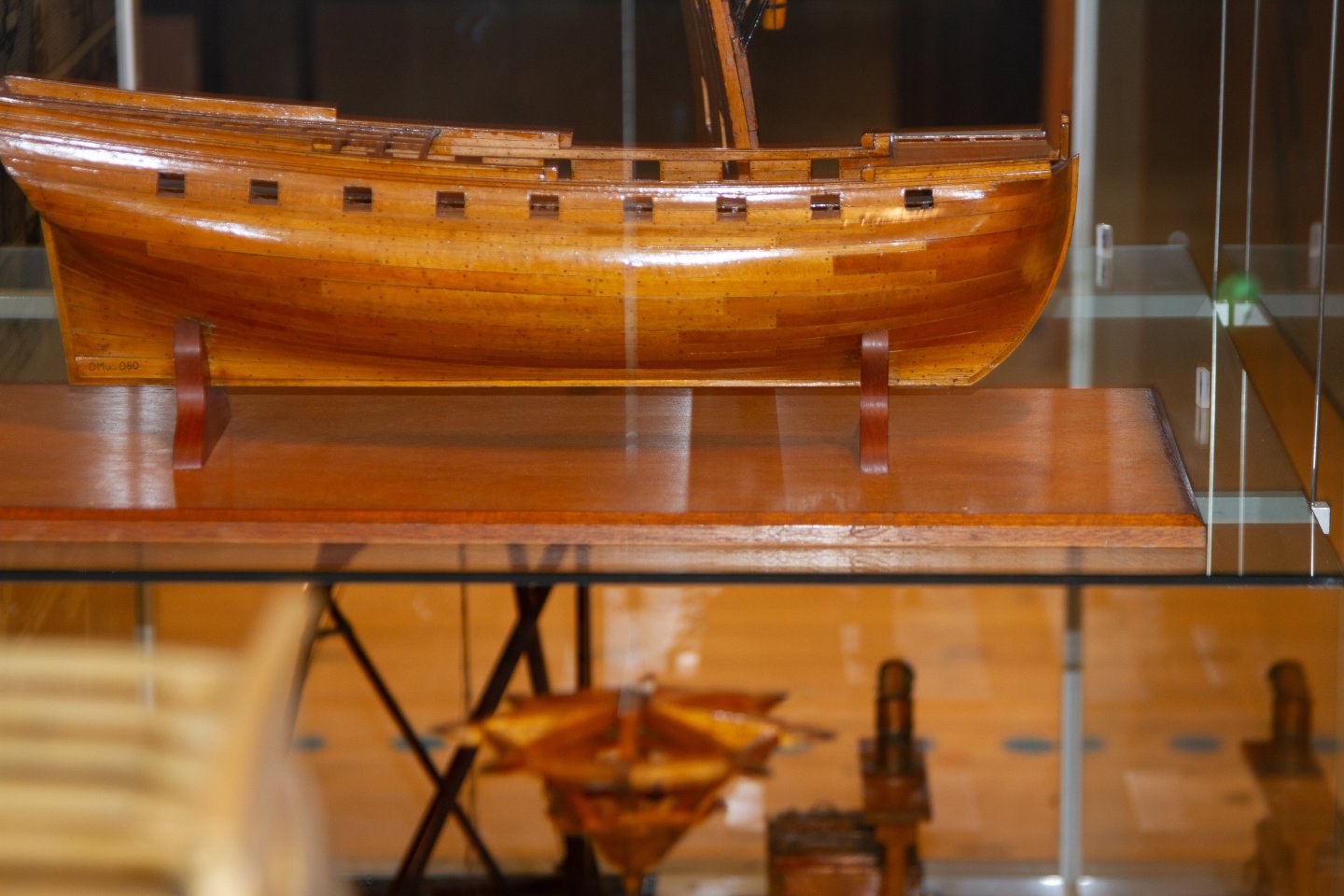
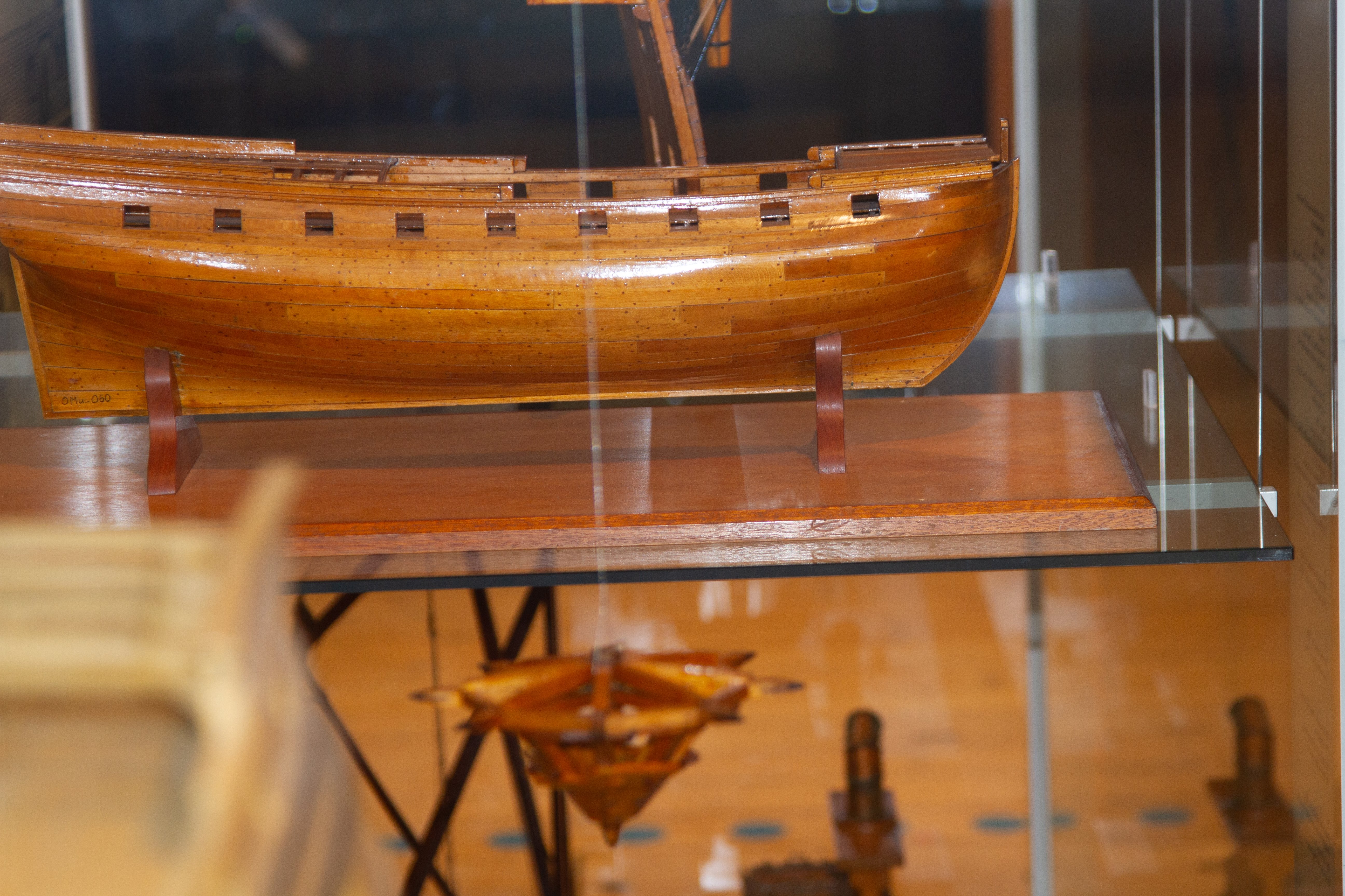
4 hours ago, druxey said:I always enjoy a more unusual subject! Wildmanden certainly shows nice lines. One curious point: the line of the wale looks to be conventional on the draught, but the last photo of the model appears to show this rising aft in a very odd fashion.
Happy to have you here @druxey! You touched on a good point there, the sheer plan is deceiving with regards to the wales. The 'midship section plan' (or however I should call it lol) suggests the ship wasn't built with two standing out wale strakes, rather, a more french approach was taken. The space between the lower and uper wale strakes is filled, and the planking gradually diminishes from the lower strake towards the rabbet:

So, what I'm making of the model is that the wale line is actually here:
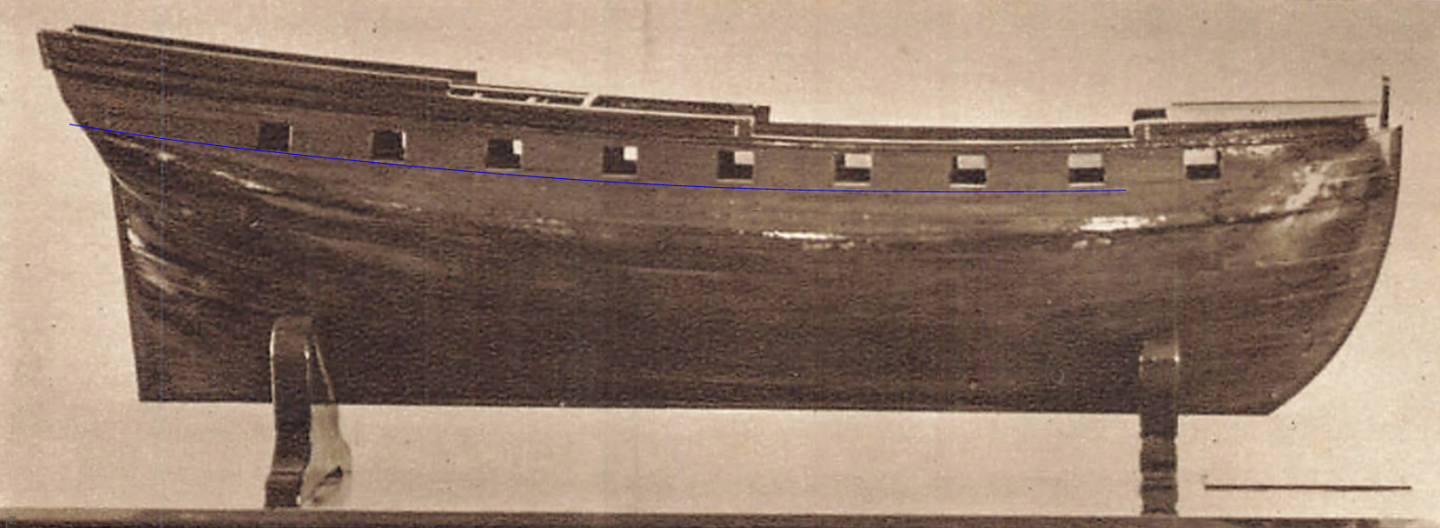
But then again, very hard to tell. Hopefully some better photos can clarify it in the future.
- Tumblehome, druxey, TJM and 1 other
-
4
-
-
This week I went through a few of Waldemar's topics, and got inspired to show my progress on "reverse engeneering" the lines of Wildmanden, and to eventually get to a full 3D model of her. While I'm far from being as knowledgeable as he is in all matters ship drafting, I believe I can go a long way with good sources, the input from the great people on MSW, and a fair amount of trail and error. In that sense, I insist that you guys point out where I've got something wrong, even if you're not sure of it yourself, we might learn something by looking into it.
My limitted experience trying to redraw plans was with an english 23ft launch. I've gone further along with it than what I have posted, but my law school's final paper got in the way of the project, and the drafting attempt got me to realise that I wouldn't be able to reach my end goal to a standart that would satisfy me. You see, the main reason I actually picked that specific launch to reconstruct was because that's the size of launch Inconstant (1783) would've carried. At the time, I meant to eventually reconstruct the frigate, but through my trials with the 23ft boat I learned that redrawing her plans would require more guesstimates about various dimensions and designing techniques than I'd be happy with. That got me back to the ship choosing board, until I eventually landed on Wildmanden, and other A. Turesen (her designer) boats.
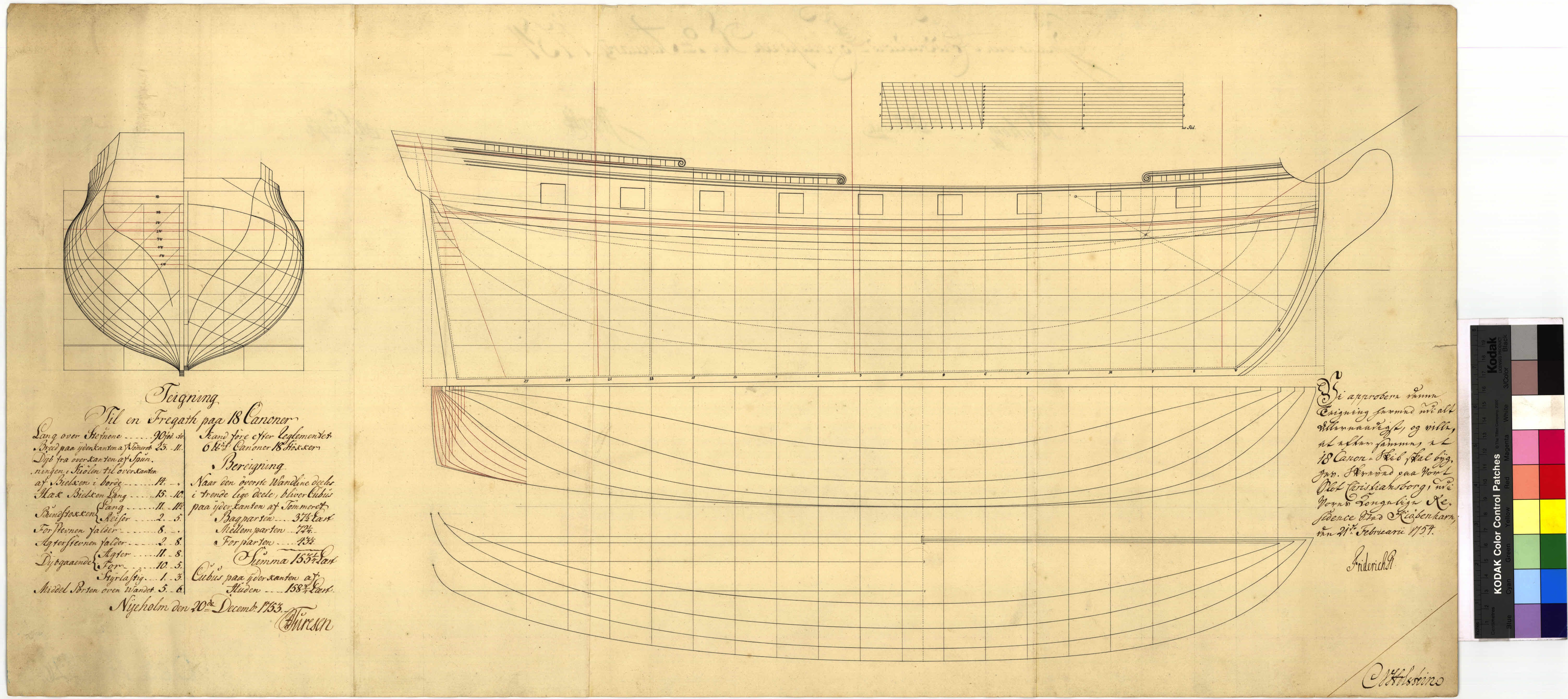
Why Wildmanden? To begin with, I find her lines very pretty: she's got a good amount of sternpost rake, unlike most of the french earlier "true frigate" designs; it isn't too long relative to its breadth nor does it have extreme tumblehome, which, again, are recurring themes with french designs; unlike it's english counterparts, it's body looks much sleeker, the swan sloops, for instance, feel top heavy to me; the distance between the main rail of the beakhead and the upper cheek rail on english sloops and frigates is often too narrow, and the main rail leaves the ship's hull too low. Most importantly though, the many Wildmanden plans present an abundance of dimensions and illustrate and explain many drafting techniques that are paramount to an accurate reconstruction. Not only Wildmanden, Turesen has left plentiful drawings, equally detailed, and as the Danish Archives make those available in high resolution, they make for excellent comparative material. Specially relevant for this reconstruction are those for the Hvide Ørne (1753), another really beautiful frigate in her own right; A1246c, a brig design that was never built; and, surprisingly, the plans for Fredericus Quintus (1753), a full on first rate ship of the line, that, in spite of being of a different league of ship, was drawn by many of the same rules observed on the aforementioned designs.
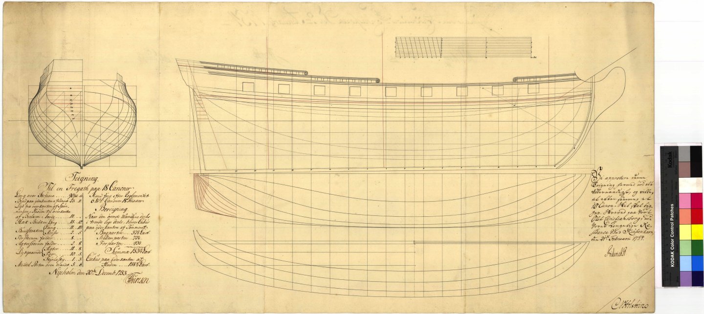
Above, the plans for Wildmanden. Although a fregatten by Danish denomination, her dimensions are more akeen to a british sloop of war, or a french corvette.
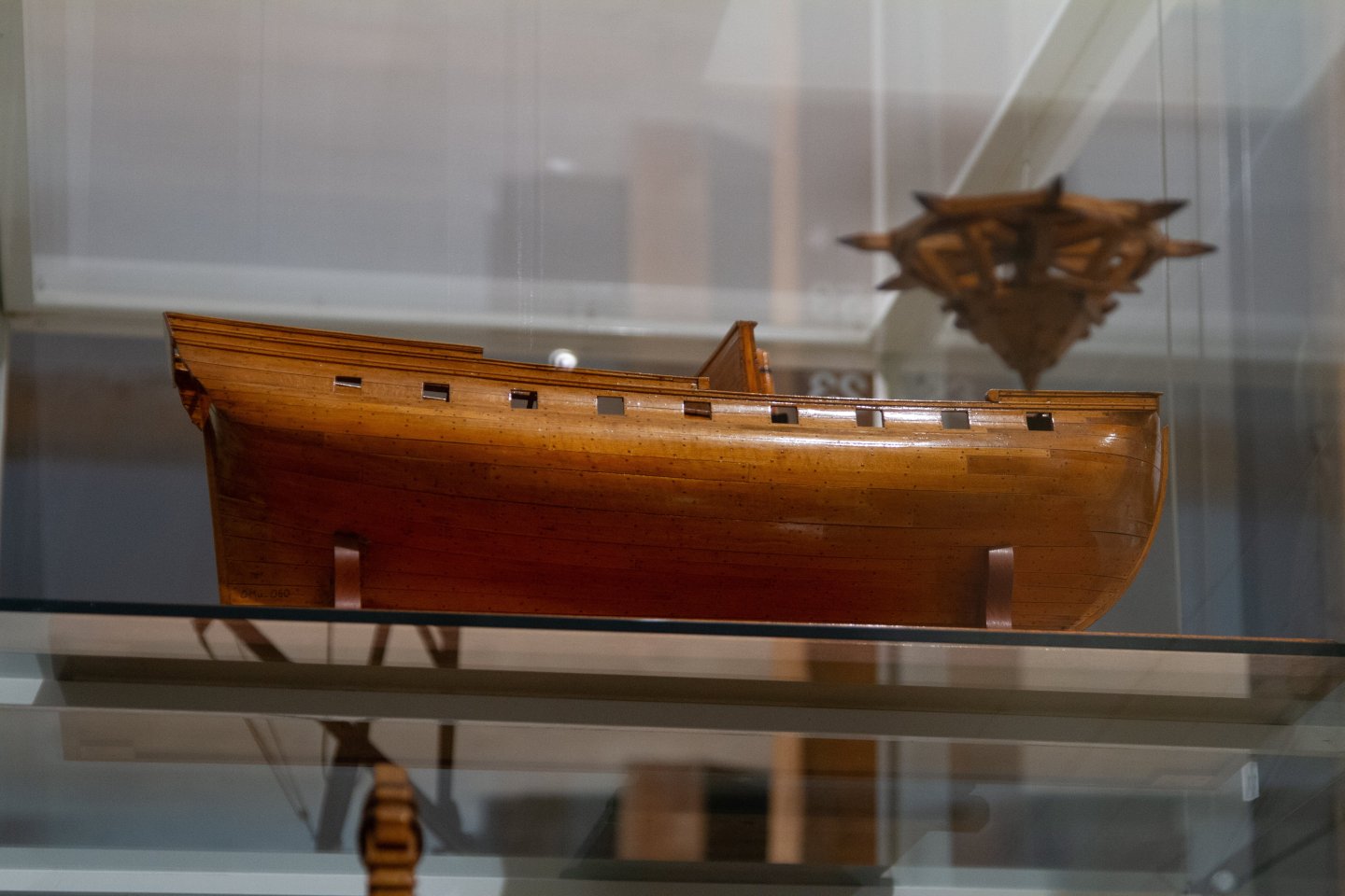
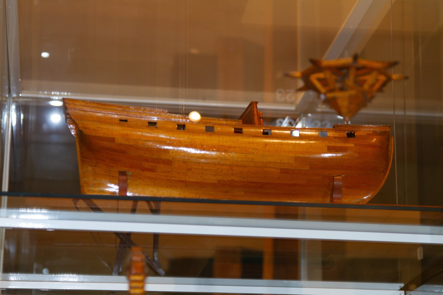
The Krigsmuseet holds a contemporary model of Wildmanden, unfortunetely, I could only find two photos of it. If somebody happens to have some more angles of the model or otherwise happens to visit the museum and would be willing to snap me a couple more images, it'd be much appreciated!
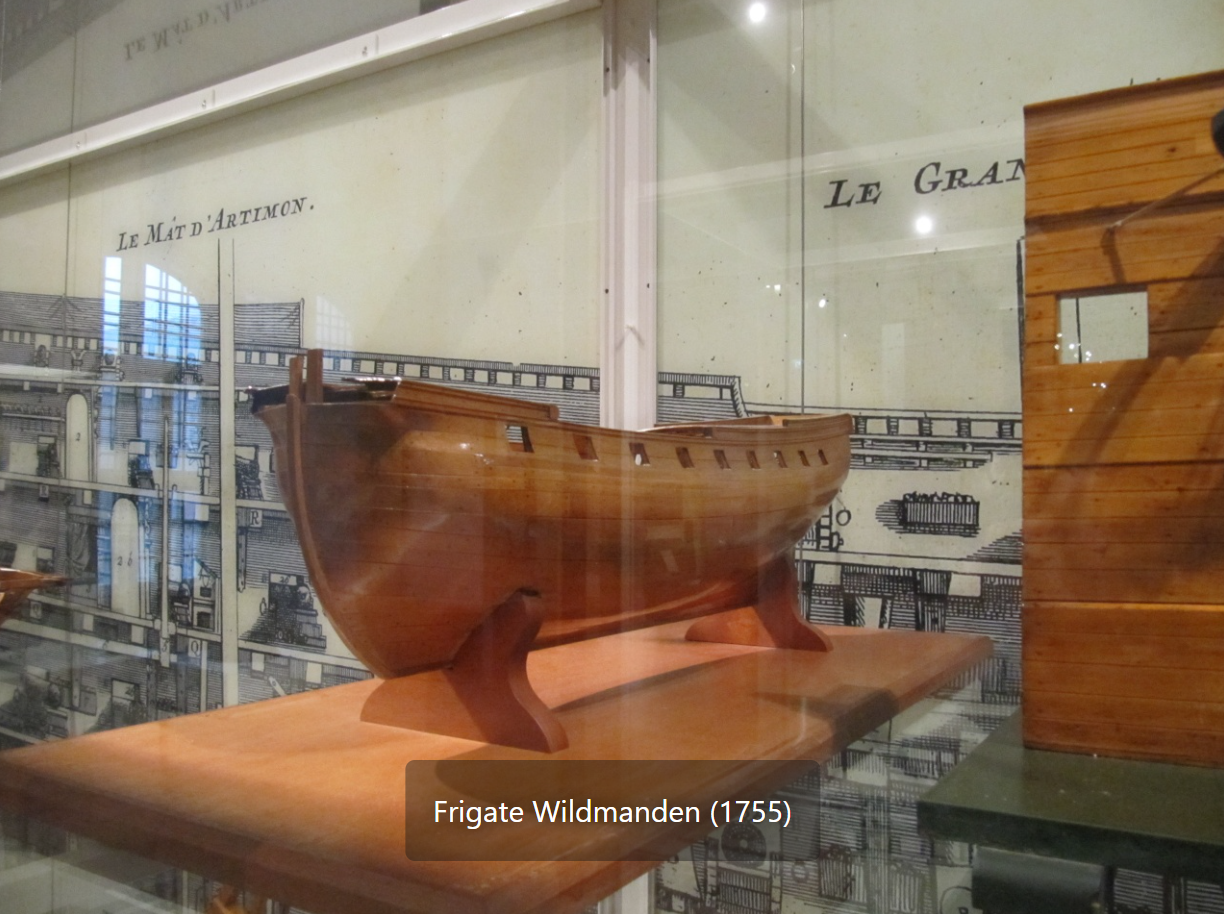
(credit: modellmarine.de)
The goal here, at first, is to showcase and discuss the methods for forming the different lines of the ship, together with findings in proportions. I hope to have you along. The next post, we'll begin by adressing wales, gundeck, and sheer line.
-Arthur
-
On 11/20/2025 at 3:41 PM, Beckmann said:
Hi Arthur,
I recently posted some of my photos on our german homepage, where I am member of. https://www.arbeitskreis-historischer-schiffbau.de/mitglieder/ontour/schiffsmodelle-in-daenischen-museen/
Matthias, thanks a lot for the link, those are some great references. I probably will be bothering you more down the line for some extra photos 😁. I wonder how much of Fyen's rig was kept original. Also, thanks for the feedback on the book.
And, @TJM thank you for pointing me towards the guns and the cadets' book. Good thing too that going through the archives is quite fun, a bit of a treasure hunt.
Cheers, guys!
- Keith Black, Canute and TJM
-
3


La Renommee 1744 by ChrisLBren - 1/48 - 2025
in - Build logs for subjects built 1501 - 1750
Posted
Looking very tidy! Lovely work