HOLIDAY DONATION DRIVE - SUPPORT MSW - DO YOUR PART TO KEEP THIS GREAT FORUM GOING! (Only 20 donations so far - C'mon guys!)
×


rtropp
-
Posts
936 -
Joined
-
Last visited
Content Type
Profiles
Forums
Gallery
Events
Everything posted by rtropp
-
Dan, There is a different pattern for the six hull strakes just below the whales that seems to be repeated on the deck. Can you tell me about more about the origins of that pattern. I only see it rarely in the builds here or the models in museums. Thanks, Richard
-
Mark, I think we both have the same, discontinued MM Micro mill (#84659). I too am considering the Sherlines as replacement but would like to hear more about the 10,000 rpm upgrade to the MM. While it seems to working ok as is, I do not have a comparison to higher speeds so might be interested. Richard.
-
Hi Bill, I have an older version of the Micro Mark mill that I got on a close out sale. It has two pulley steps (speed zones): 70-1600 which i use with metal, and 70 to 2800 which I use for wood. I have had no problem with milling wood. As mentioned above, I do need to feed slowly. But, the parts are so small that slow does not really seem a chore and the parts are very smooth after the milling. This is my first experience with milling so I don't know if faster speeds would really help that much in creating smoother cuts or saving time. More important for me is the accuracy/precision of the x-y tables and the vertical (z) adjustment. I have experienced some difficulty with the precision and smoothness of movement. With such small tolerances, the slightest wobble, backlash or misalignment will ruin the piece. Also important are the range of accessories, which, by the way, end up costing as much, if not more, than the mill itself. This is where the Sherline stands out. I had the opportunity to visit their factory and museum in southern California and was impressed with the quality of their tools and range of accessories. I first wanted to see if I use the mill enough to warrant the expense of trading up to the Sherline. I do use it a lot for milling as will as precision drilling (even though I also have a Proxxon drill). That said, I would be curious to hear the experience of others who have the Proxxon mill. Richard
-
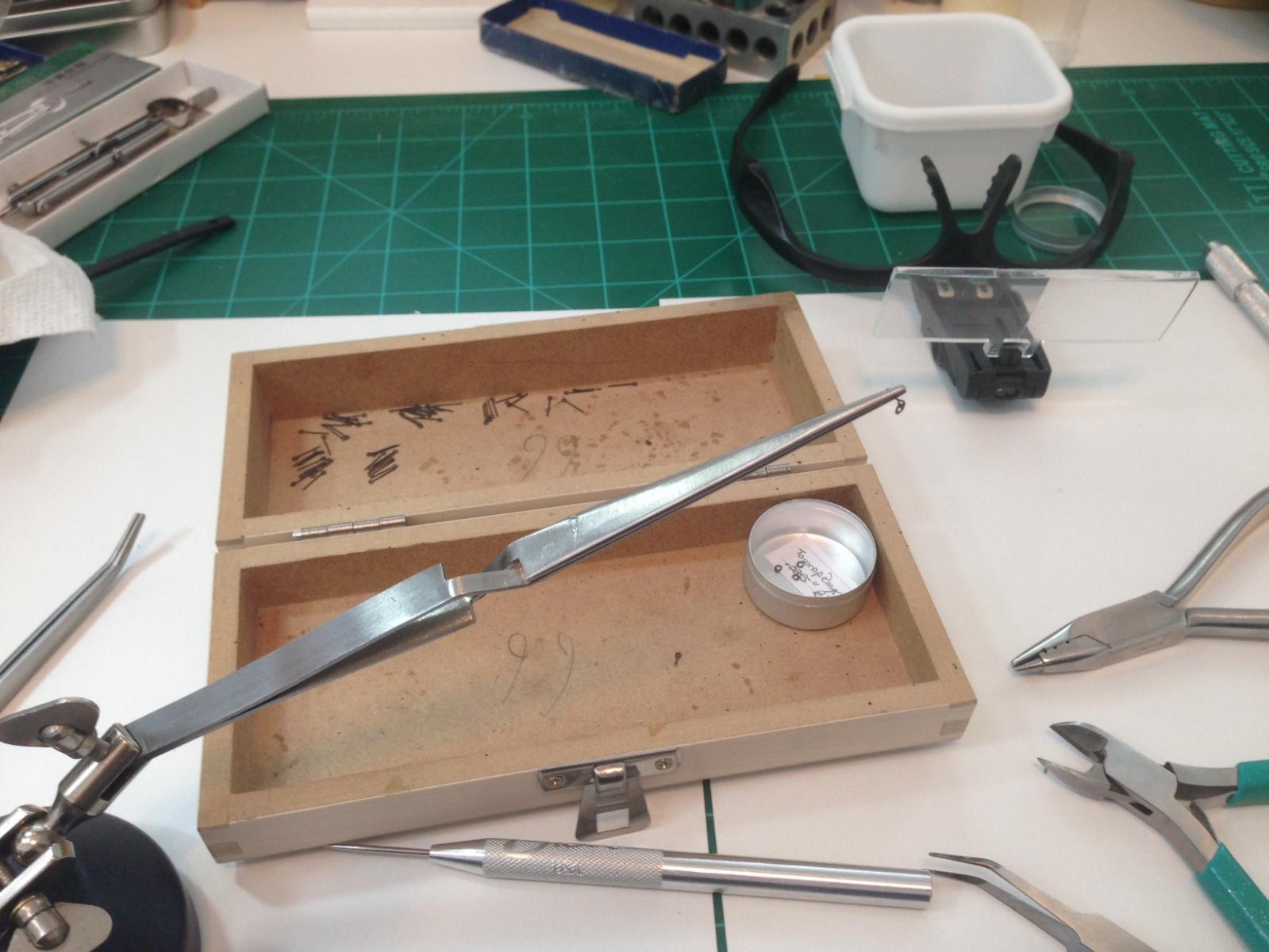
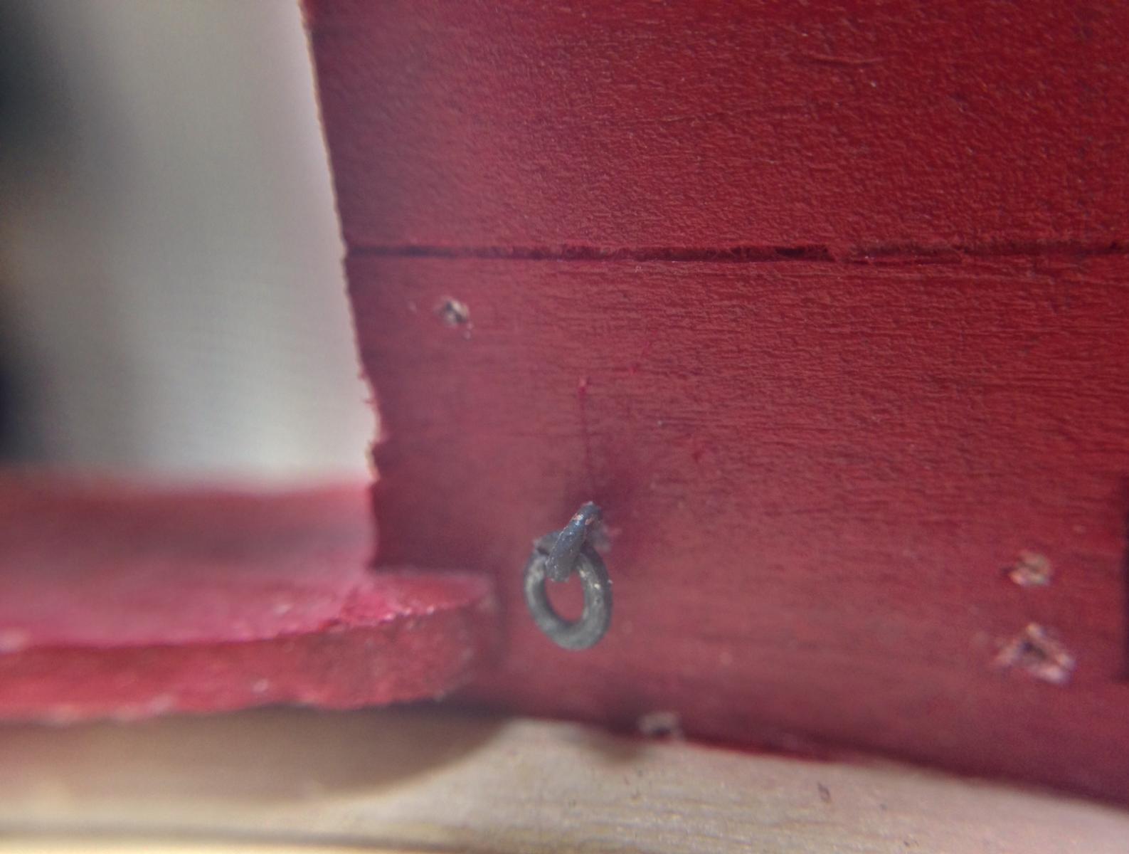
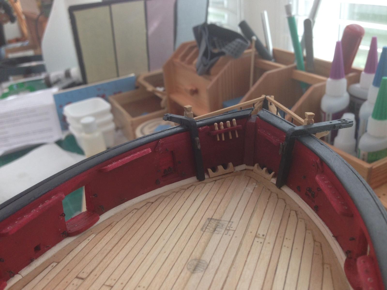
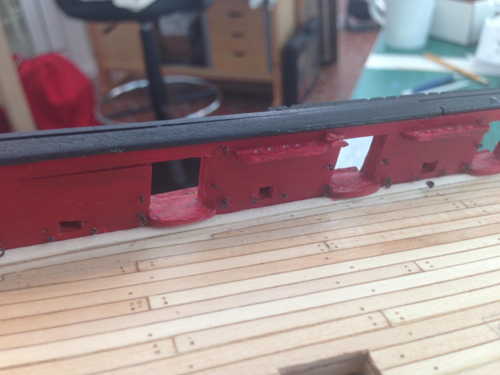
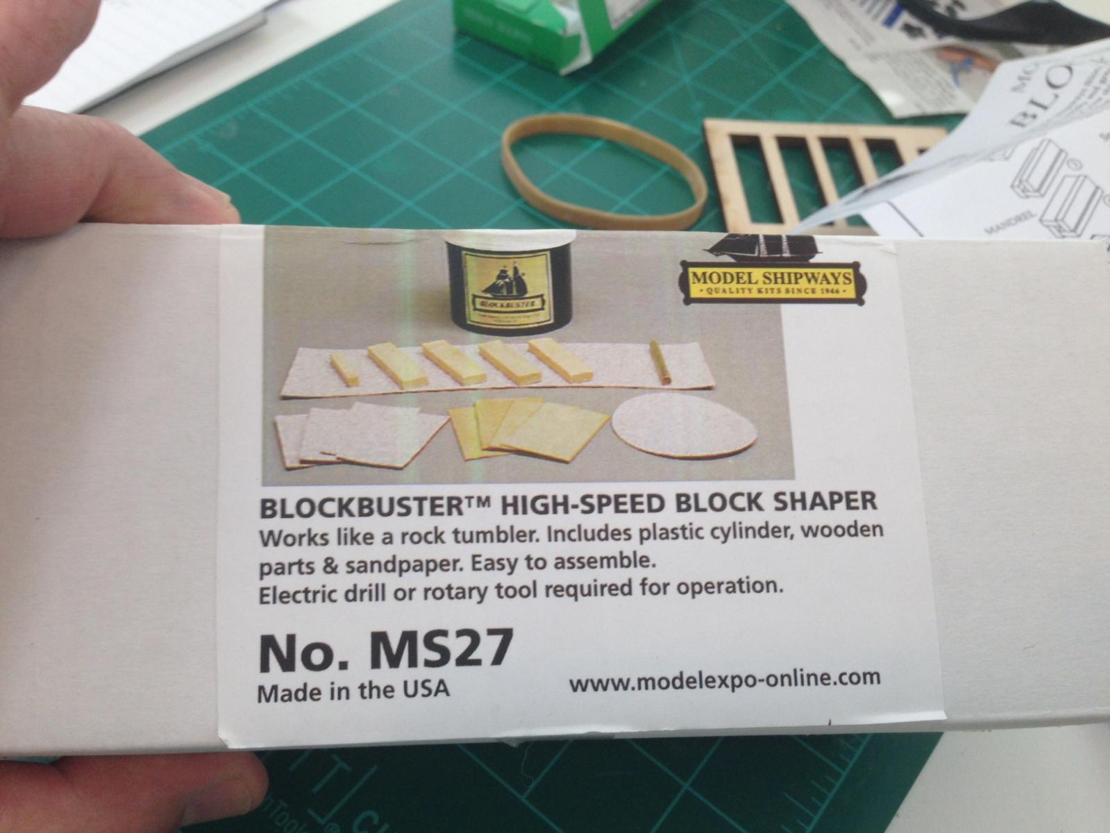
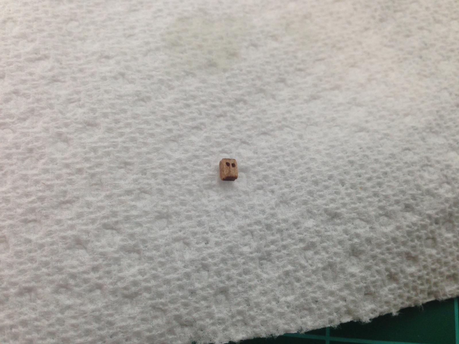
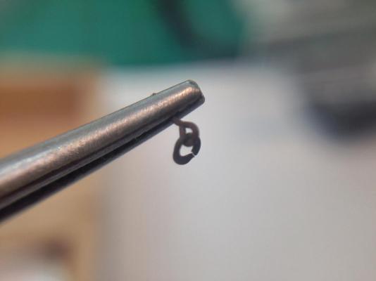
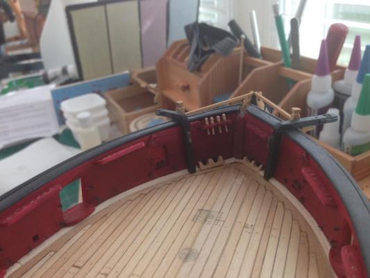
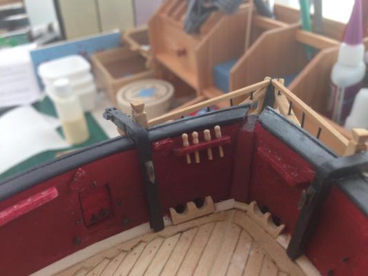
I'm finally close to the end of the Inboard Bulwarks section of Chapter Eleven.Making the belaying pins and the ring bolts took some time. I tried to add the ring bolts as follows: This did not work out, the ring kept slipping. So I altered my method. I drilled a hole in a small flat sheet and with the eye of the bolt just at the level of the surface it was easier to manipulate the ring and close it. These pictures show some of the work on the inboard bulwarks. Except for the belaying pin rails, none of it is permanently glued. I may glue most of it but not the rings for the carronades. Given my inexperience when starting the build, I may need to move things around to better fit the carronades. Also, not sure of my skill at tying off the gun ropes so may need to tie them off, then glue to bulwark. I painted the rails and the cleats before attaching. I also inserted a small pin in each to strengthen it when glued. When cutting previous eye bolts to size I saved the cut off and that's what I used. The will have to be retouched but I figure that will be easier than trying to paint them after attaching. I have mounted some of the belaying pins to see how they would look. Not too terrible for home made. There is some inconsistency in size but I will try to match similar ones on the same rail so they don't look too out of place. I made enough for the bulwark pin rails so I will need to make more anyway. I can always replace the ones that look really our of place and I would really rather use the ones I made even if those supplied are "prettier" or more consistent. I am now working on the block that ties to the traveler. Boy are those tiny. I had this device from model expo to round out the edges. It works pretty well but I think it needs finer sandpaper. I also reamed the holes a bit to clean it up. I used a satin poly to finish it up. now I have to rig it. I had a couple of questions: Did anyone finish these differently? Which supplied threads did you use to strop... did you serve or just tie it off? What type of glue did you use to attach the eye bolts, etc to the bulwark? Thanks Richard


-
Thanks Druxey. Now, I probably have hijacked Chuck's site. Apologies.... Richard
- 1,051 replies
-
- 3
-

-
- cheerful
- Syren Ship Model Company
- (and 1 more)
-
thanks Chuck. Especially since the current batch are mostly for cannon, there should be little strain on them if any. JD, is this true for brass and/or copper rings? If so, I will try this. I think it will become useful when later rings will experience some stress. Thanks, Richard
- 1,051 replies
-
- 3
-
-
- cheerful
- Syren Ship Model Company
- (and 1 more)
-
Chuck, When you use split rings on eyebolts, such as on the bulwarks for the cannon, do you solder the split ring? Richard
- 1,051 replies
-
- 3
-
-
- cheerful
- Syren Ship Model Company
- (and 1 more)
-
Gaetan, Do I understand correctly that when making the grates, you stacked multiple blades on a Byrnes Saw? Richard
- 728 replies
-
- 3
-
-
- le fleuron
- 64 gun
- (and 1 more)
-
Tim, looking good, I will enjoy following along. What other resources/documents are you using besides the Anatomy Book? Richard
-
Hi Jesse, I follow your build log and saw the post about using the hand drill. Before I had the Proxxon lathe I also used the hand drill. I had a rest similar to yours but added a tool rest which is necessary for lathe cutting. Also I made sure that the block holding the end of the piece is fairly tight around the wood to prevent vibration. It is near impossible to use gouges if the piece is vibrating too much. The cutting tools need to be very sharp. That's key. I have an inexpensive sharpening block that is made by Flexcut. It has a number of shapes that fit the various gouges and angles. Before trying to lathe I did a lot of reading and U Tubing (U Tubing??? not really a verb but...oh well). It is important to use the gouges as you would in a full size lathe. That means a support / tool rest to hold the tool while working it. The angle of the tool and position in relation the work piece is also important. U-Tube is a great source for learning how to use the lathe. Any of them, full size or small, will have the same basic operating principles. That said, I make extensive use of Files for the final shaping and smoothing. I also take a final pass with very fine sanding twigs. My process to use the gouge to bring the piece to its maximum diameter. Then I move to the smaller gouge to get things to final shape. Finally, I go to work with files. I have sets in a number of grades and sizes, all small for modeling. The sanding twigs do a great job of smoothing when the area is really narrow, like in the belaying pins. It became a lot faster to use the micro gouges as lathe tool rather than rely on files alone. Richard
-
I felt the same way about the red. I ended up mixing two badger marine colors to get a red that was a bit darker. Richard
-
As an additional thought, I am going through some of the other builds to see what they seem to use most. Richard
-
Thomas, I understand. I think I am getting closer to investing in a Sherline. I will probably go with the DRO (digital readout). I am trying to decide which accessory package to get with it. At this point, I dont want to overbuy, but might as well get what will be needed for the build. Richard
-
Thomas, Thanks for the tip. Do you know of any references, pictures or links that would show how to use analog measurement devices with a wood lathe? I am having some difficulty visualizing this. Richard
-
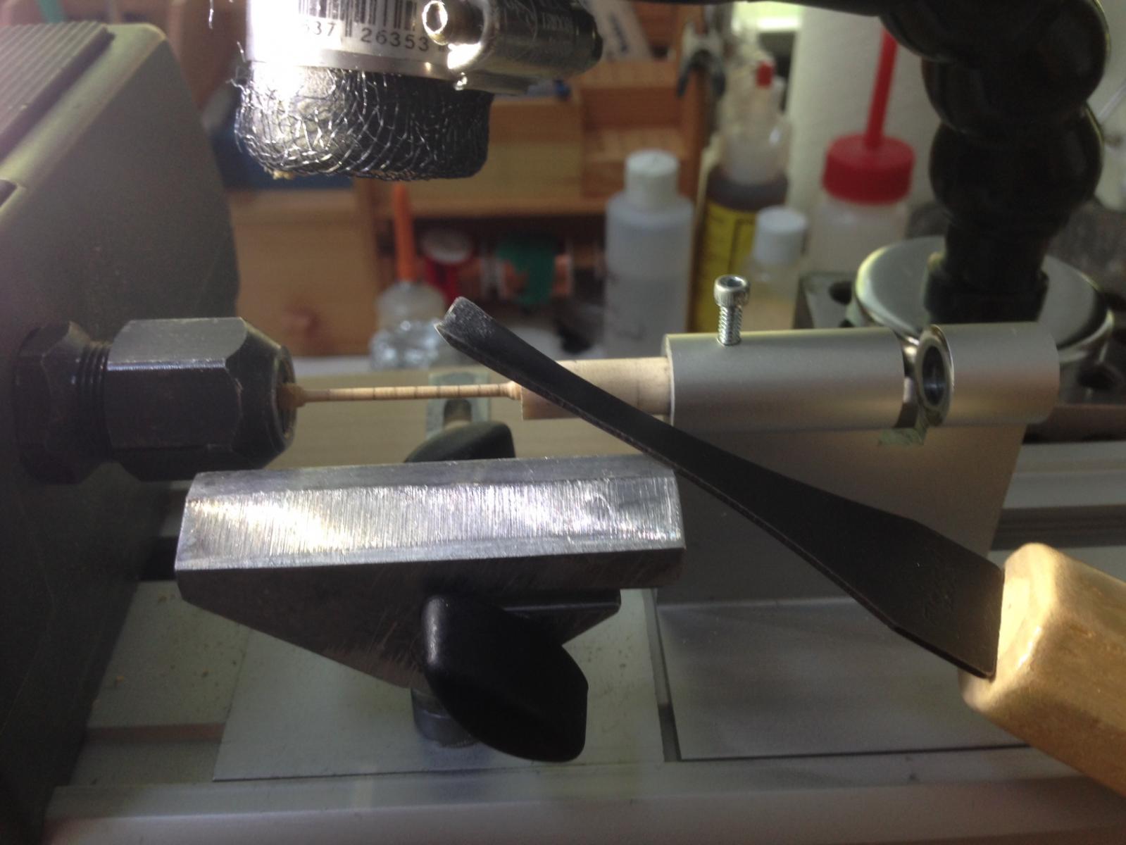
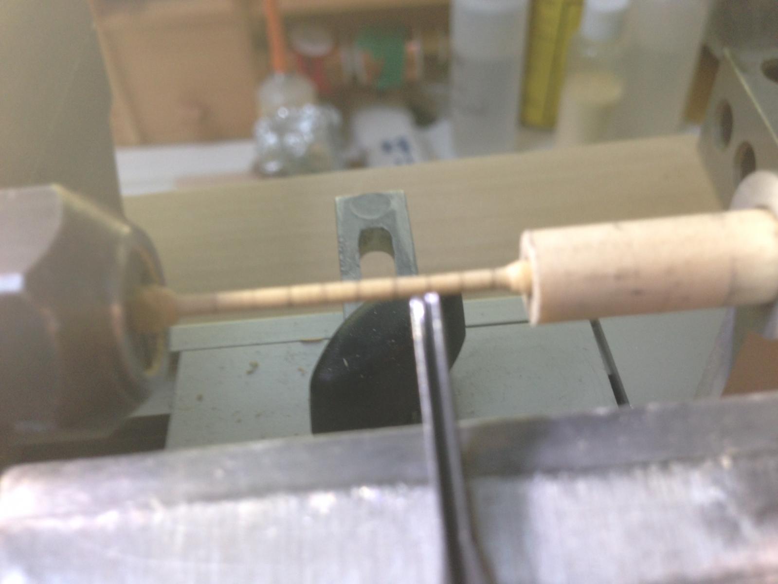
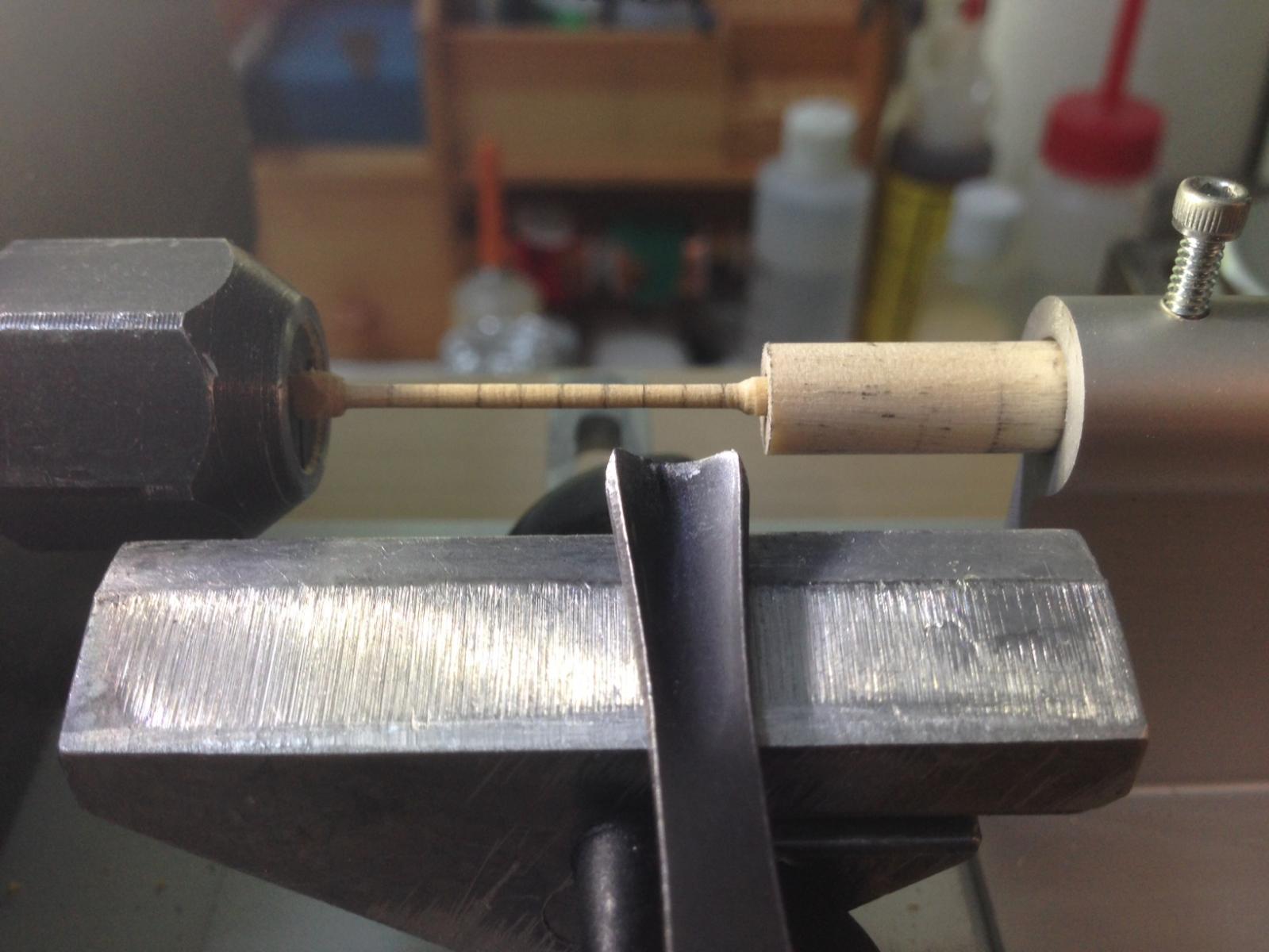
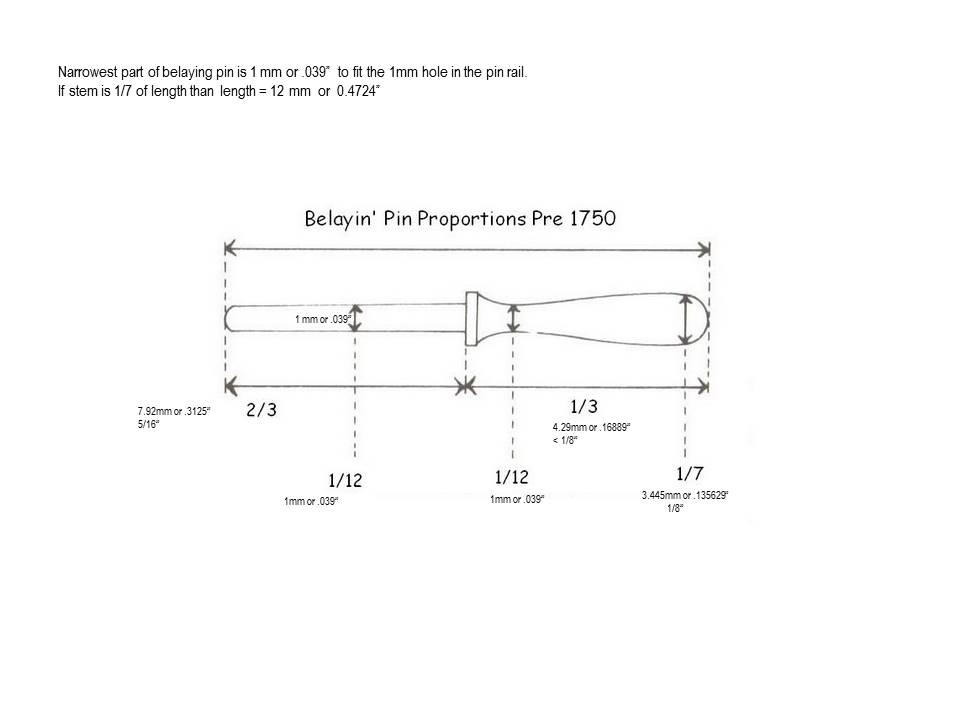
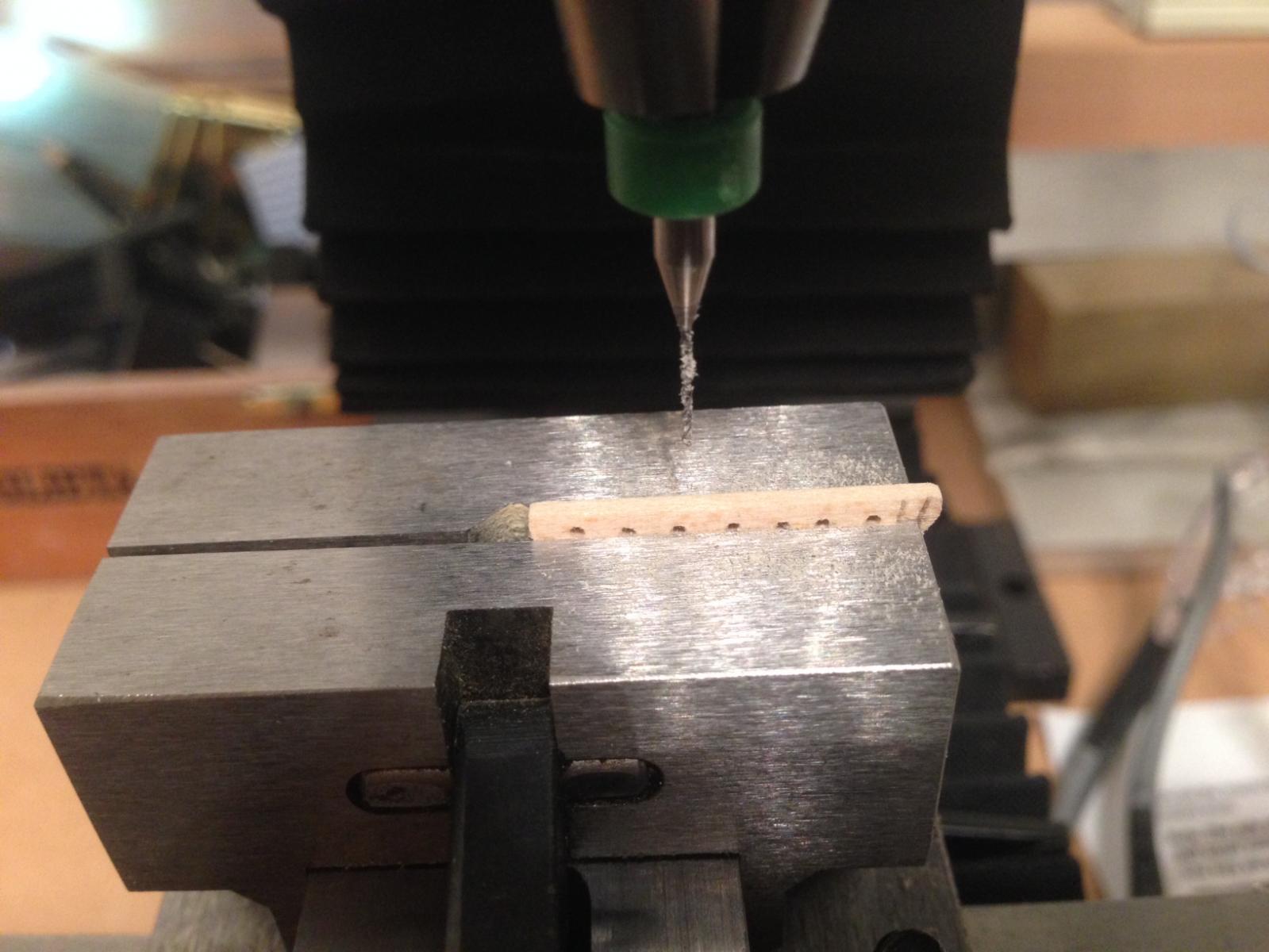
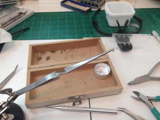
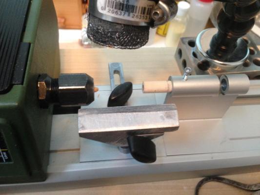
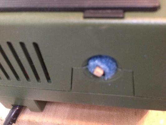
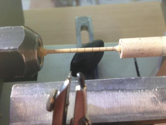
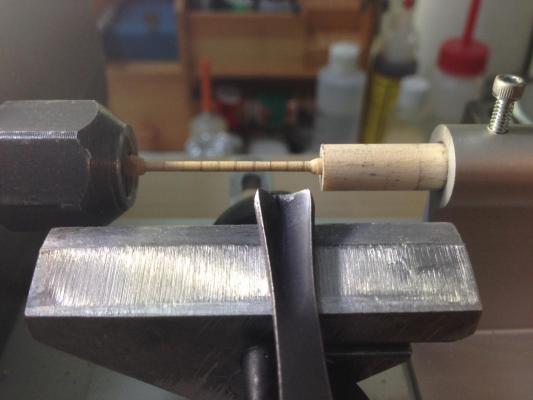
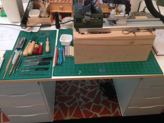
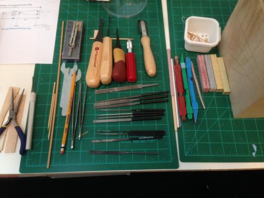
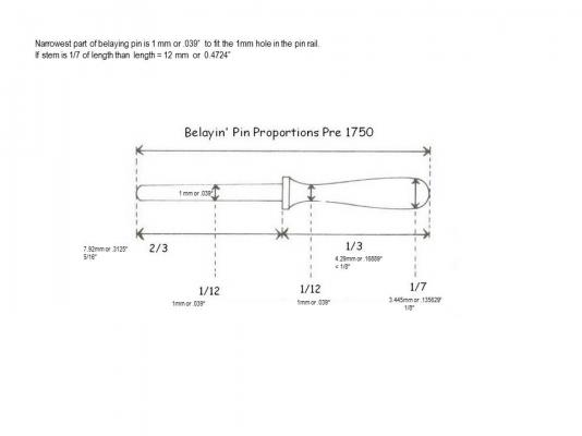
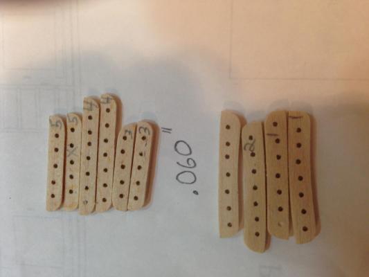
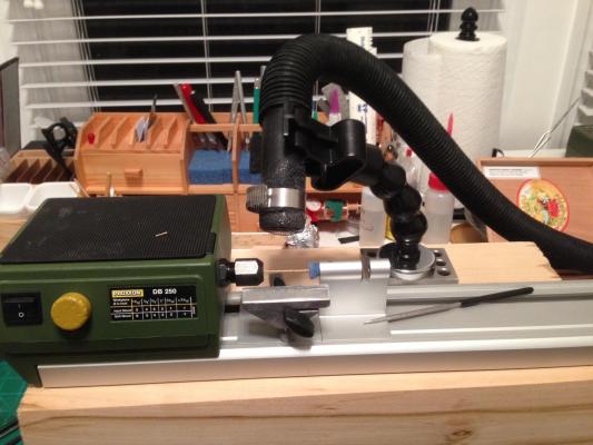
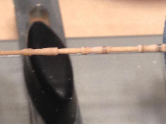
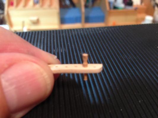
I have some more detail on fabricating the belaying pins. Also a couple of changes. The first change was to drill a hole in the center of a wood dowel to use in the tail stock instead of the foam piece. It holds the work piece better. I was concerned that the wood against wood rotation might cause some burning but had no problem. I could have worked without the tail stock support, but then I would only have been able to do one pin at a time. With the support from the tail stock I could do three at a time. Four was too much and the piece would bend interfering with the turning. I used the foam to prevent the work piece from whipping around in the feed shaft. I used the following diagram to work out the proportions. I do not remember where I found it. The fractions were part of the diagram showing the relationship between the various measures. The millimeters are my entries showing the actual measures for the Syren's belaying pins. Since I was sure of the 1mm diameter of the lower pin (it came from the practicum and was indicated for the pin rail), I used it as the base measure and worked back to figure the remaining measurements. (taking measurements from the tiny brass pin was difficult. As the diagram shows, the length can be divided into three equal parts. I used a compass set at the one third to mark the segments on the work piece. The first segment was the handle of the pin, the next two thirds were the lower section. I was able to work nine segments (3 pins) while keeping a stable work piece. I kept two small dividers at the required diameters to be able to constantly measure as I worked. These three inch tools were a real help. If anyone knows a source for more, especially if there are any that are smaller, please let me know. I was having difficulty finding lathe chisels small enough to work the pins so I tried some of Flexcraft's smaller chisels. These worked very well. I first rounded out the wood and brought it down to size using a gouge. to shape the pin, I used their smallest gouge. To bring the belaying pin to final shape and size I then used various files and sandpaper. Here is my tool layout. The entire work area did not take up a lot of space. I used a large piece of basswood as a base for the lathe to bring it closer to eye level. My back really started to ache after doing one or two :-) One problem with this process and using the Proxxon wood lathe is the difficulty in maintaining consistency between pins. Your pretty much free handing the cuts (even with the tool rest) and at that size it quite a task. I focused on the top part since it would be the most visible, and will try bring the length of the lower pin to size as I install them. They are not as good as the supplied pins, but I have a sense of accomplishment having been able to make them. So, like the figure head, I will use them. This experience has me getting closer to a purchase decision on the Sherline lathe which seems to be the lathe of choice by most of the folks at MSW. I would be curious to hear if, for this type of work, digital readouts would be worthwhile to get uniformity between pieces. thanks for all your comments and likes Richard


-
Hi all, I could use some help. I am not sure I really understand when to use an eyebolt and when to use an eyebolt with a ring. I am using the inboard plan. I thought it was when the icon was horizontal it signified and eyebolt and when vertical it called for an eyebolt with ring. Is that correct or is there another way of figuring it out? Thanks Richard
-
your build looks very nice. I felt the same way about the basswood, soft and fuzzy. The copper plates will hide much of it. I switched to Boxwood after completing the hull and deck. I wish I had switched sooner. Richard
-
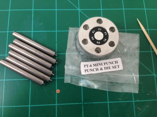
I tried various suggestions and still could not get a "clean" disc. Probably a skills issue. So I ended up purchasing one from UMM. This worked well right out of the box. The disc is the largest size using .016" thick brass sheet. I am wondering how thick I can go. I hesitate to experiment our of concern for damaging the die. There is a maximum thickness that the slot would allow but that probably does not mean it is a good idea. Richard
-
I also would like to keep the wood look. I started experimenting with powdered water soluble dye. It adds the color but still leaves the wood grain. I will experiment to see how dark I can go and still have the wood grain show. I also have ebony but until I get a worktable set up in my shed I hesitate to use it. I will experiment more when I finish the belaying pins and move on to the cannon. Richard.
- 1,306 replies
-
- 5
-
-
- syren
- model shipways
- (and 1 more)
-
Jessie, nice carronade. I am trying to turn the belaying pins and know how difficult that must be. Do you intend to paint and if so, what are you planning to use.? Richard
- 1,306 replies
-
- 5
-
-
- syren
- model shipways
- (and 1 more)
-
Thanks for the tips. Very helpful Richard
-
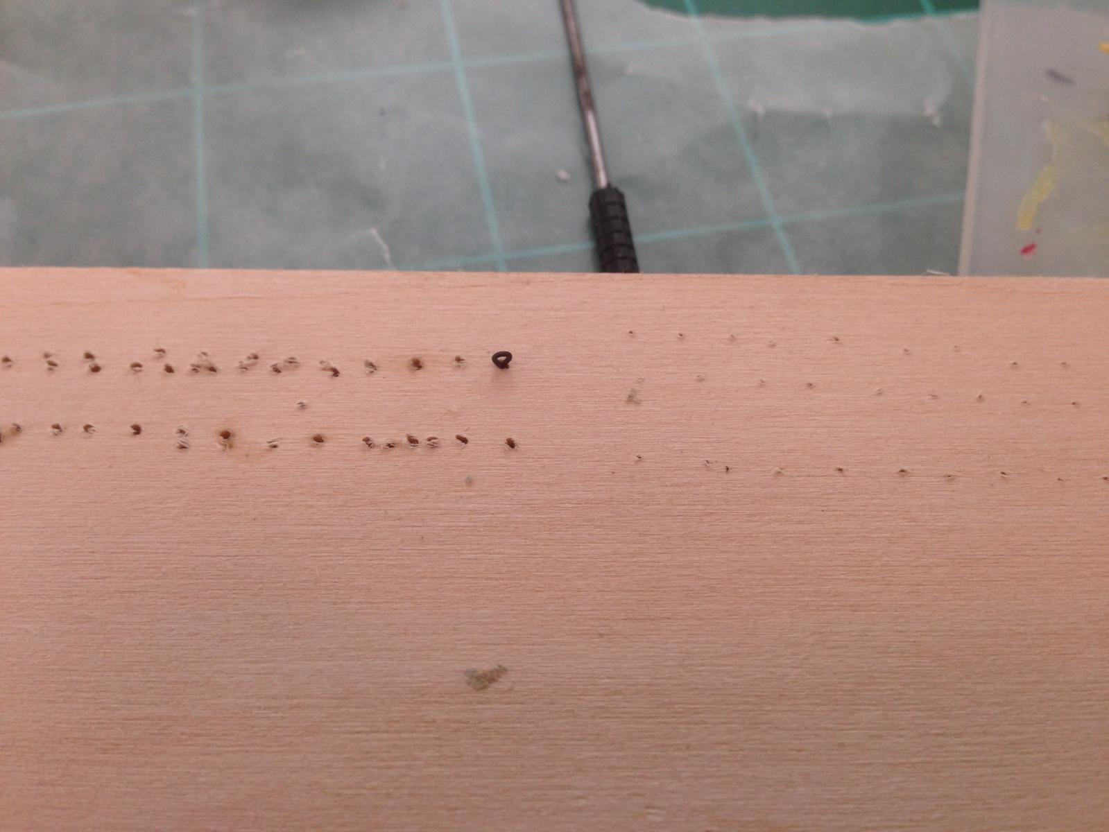
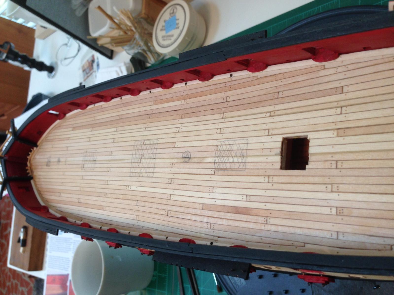
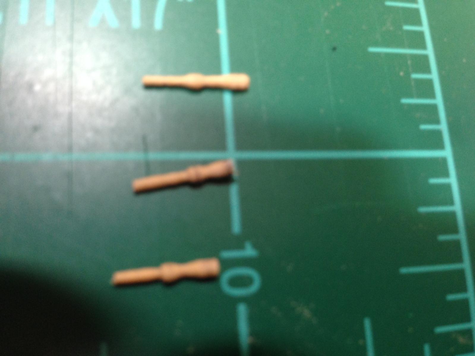
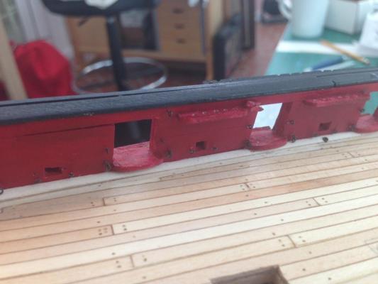
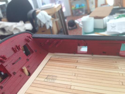
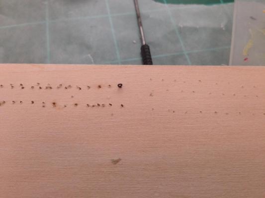
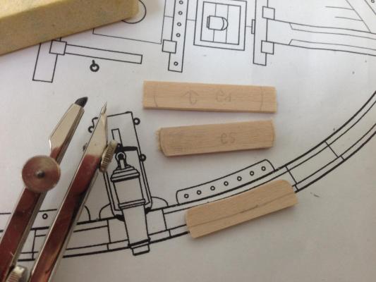
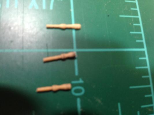
Time for another update and on to the next chapter (finally) After marking off the deck, I started work on the swivel brackets. I am a little nervous because when I did the decks I had a few mistakes that might now rear their heads. We'll see. the swivel brackets from a distance. (I really don't want to look at them close :-) ) Next came the pin rails. I am going to wait until later to install these. I started by cutting out the rails. The straight rails were pretty easy to cut and shape. For the curved rails near the bow, i first shaped the outboard edge that would be glued. I then used a compass opened to 1/8 inch to trace the curve on the opposite side. this picture gives the idea only this first one was done backwards, first the inboard side than the outboard. When I figured out the mistake I changed the sequence for the remaining ones to shape the outboard side first to make sure it fit the curve than the inside one to match. These are the pin rails cut and shaped. I will do any fine tuning during installation. Then using the mill, I created two holes in each to install wires to support the glue up. Now comes the fun (insanity??) I decided to try to make the belaying pins myself. As with the figure head, while it might not be as sharp as the supplied one it would be home made and a skill that I could use for scratch building. I figured what the heck, if it doesn't work out I could always use the brass ones supplied. First my setup I used a short strip of boxwood, first rounding then shaping. I used files rather than chisels. the piece was big enough to shape three pins. Any more and there would be too much flex on the work piece. That means some repetition waste for the ends but it shouldn't be too bad and I am milling the wood myself so the costs stay low.. I cut them after removing it from the lathe, I didn't want tiny pieces flying around the work area. As you can see there is still variation and more attention to size and detail is needed. But, for the first three practice pieces I believe it is worth continuing. I do have a concern as to whether the wood ( its really thin) would support the lines without breaking. I'll have to test that. If they don't I will try again with a stronger wood such as beech or hickory. Sorry for the blurry pictures. not my best. Richard


-
very nice Sal, I like the way you did the foot ropes and the octagonal sides on the spars. Your setting a nice path for me to follow. Richard
- 659 replies
-
- 4
-
-
- syren
- model shipways
- (and 1 more)
-
Is there a specific type of chalk to use? Thanks Richard