Jaager
-
Posts
3,062 -
Joined
-
Last visited
Content Type
Profiles
Forums
Gallery
Events
Everything posted by Jaager
-
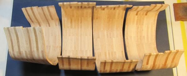
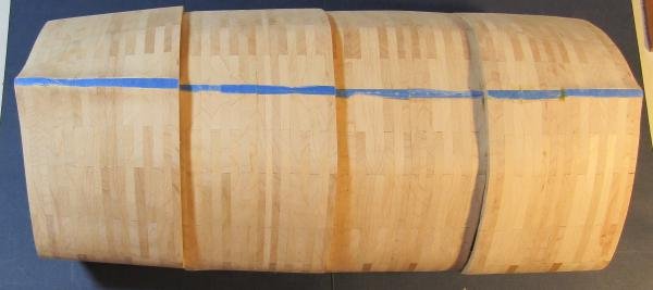
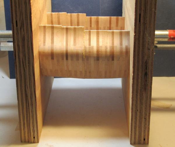
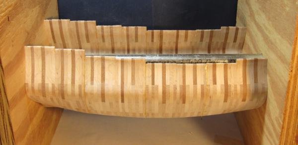
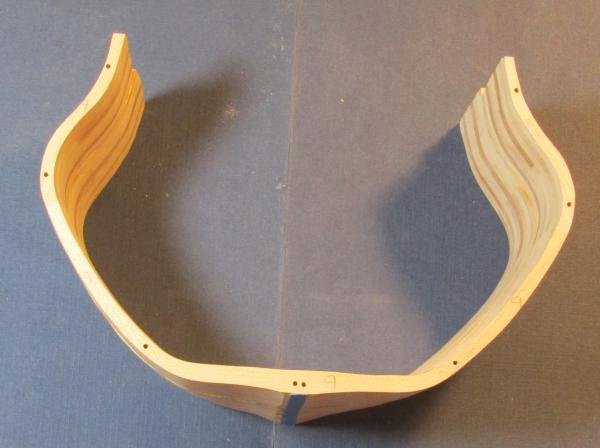
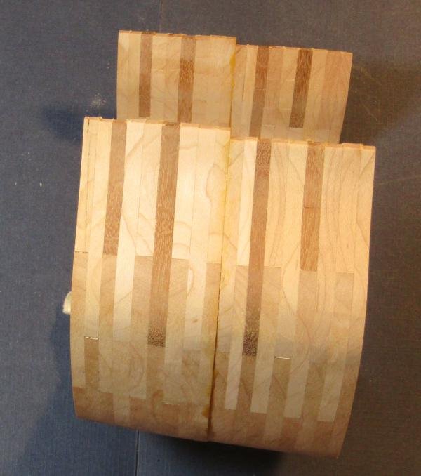
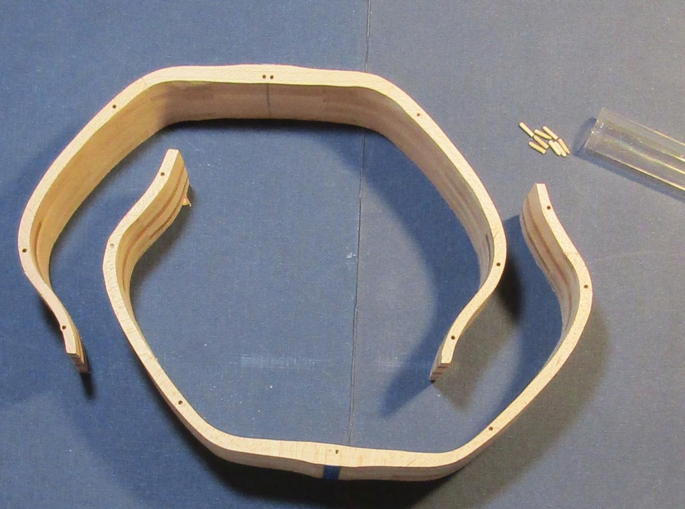
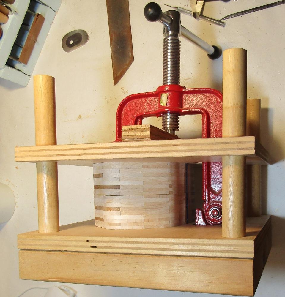
 The same process is done for VII-VI to VI-V. There are now four sections that make up the center half of the hull. These sections are too large for my pipe clamp frame press. I built a section press that has no limits on its capacity. Being firmly dedicated to over engineering, the faces of the press are two 12" x 12" pieces of 3/4" plywood glued together. The clamping force is applied using a 1/2" threaded rod, with fender washers and a wing nut. I hoped that a 1.5 inch shaft would reduce any play in the face plates., but the tolerances in the 1/2" hole is not that tight. A couple of hours for glue set and the third section is added. Two more hours and the fourth is bonded.
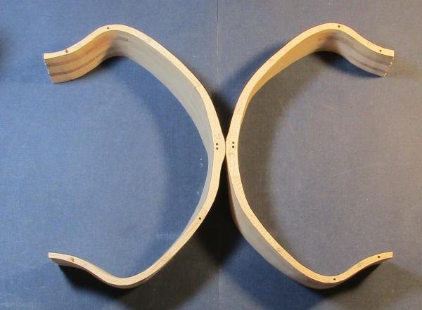
-
Newman Tools Inc has an office in Ottawa. They used to be an interface for Thurston. Thurston is no more. Madco is an alternative. Perhaps, THE alternative in this hemisphere. Perhaps communicating with Newman would provide you with information about what resources are available.
-
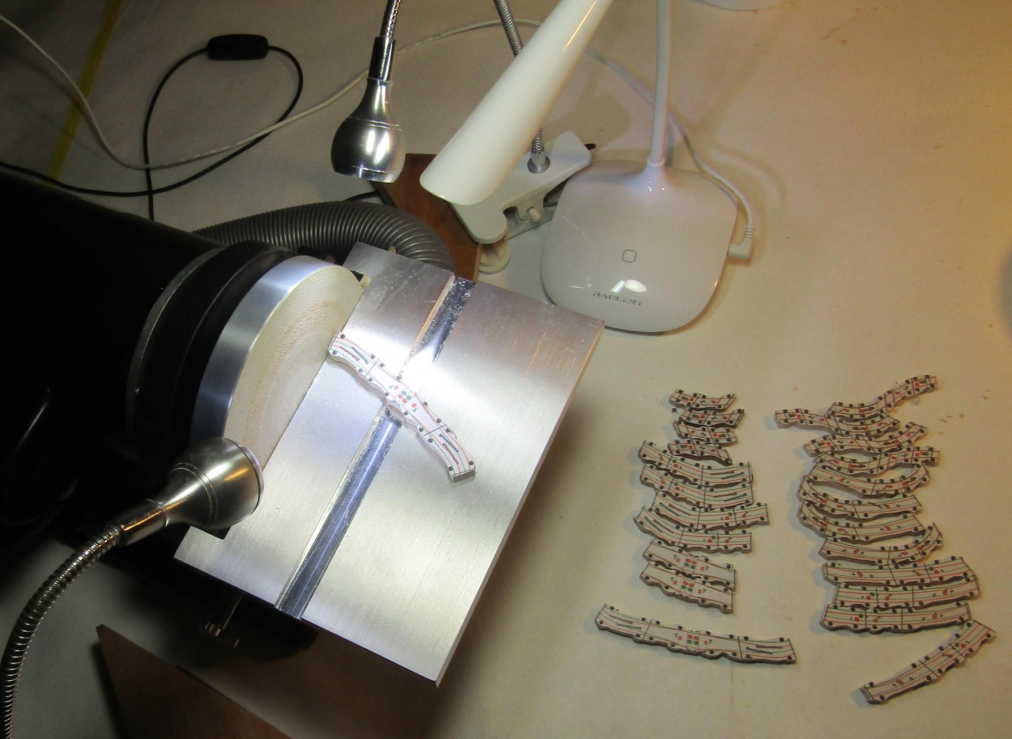
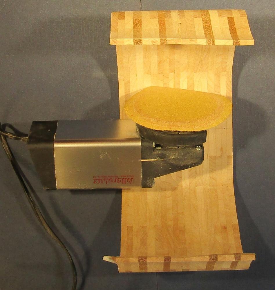
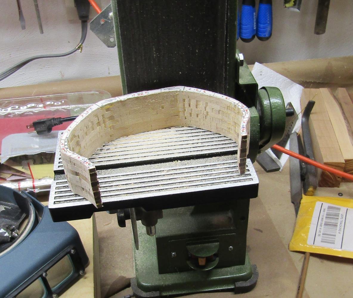
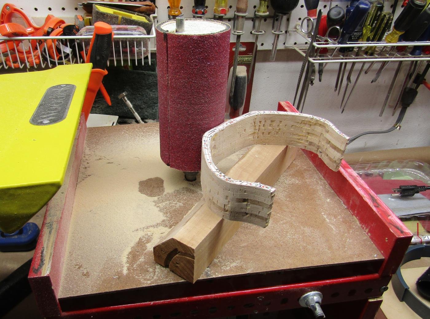
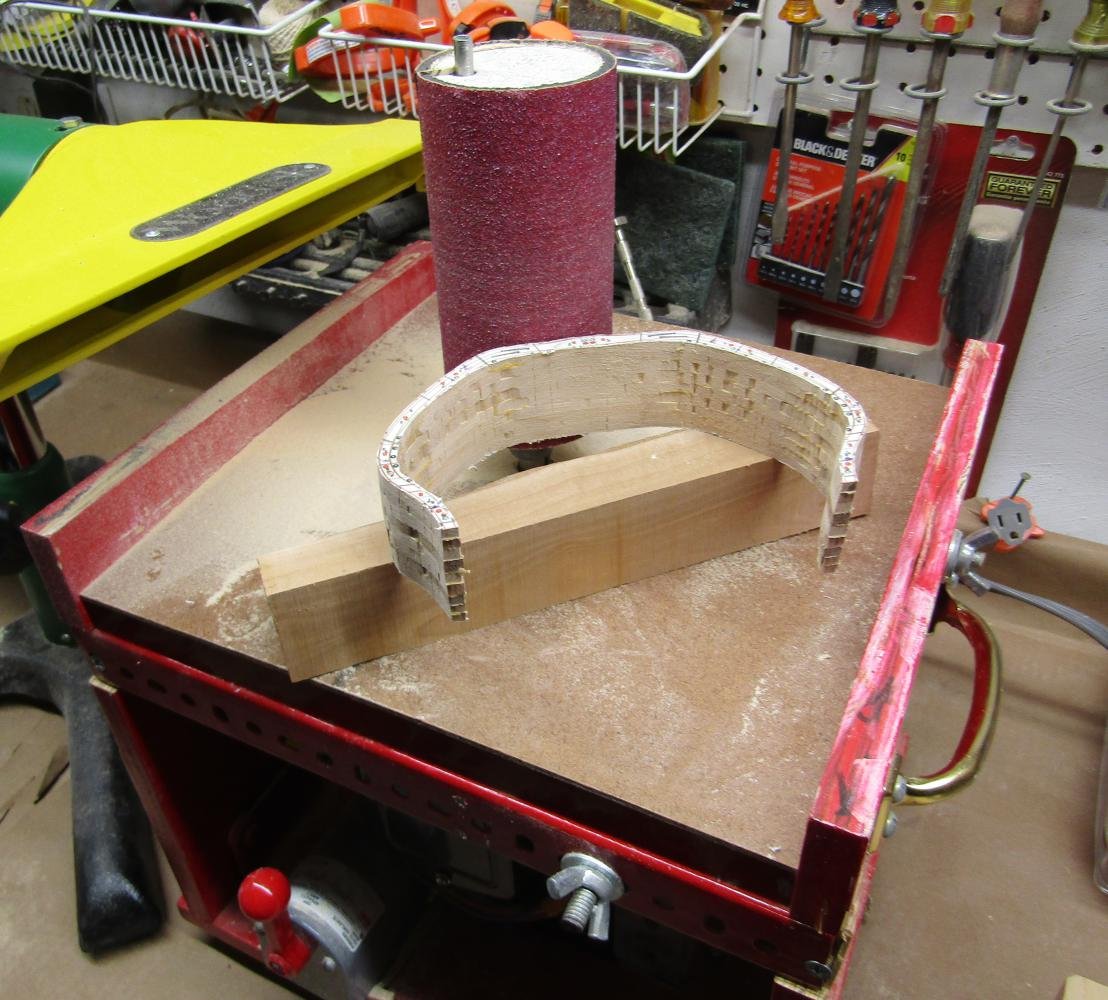
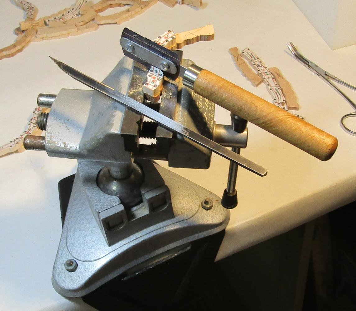
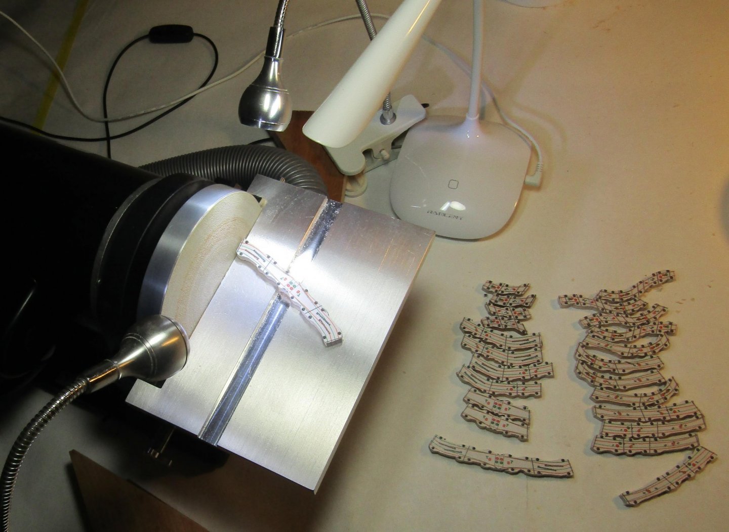
This right angle sander does an efficient job of fairing the inside join. I prefer the drum sander for the outside when the section is small enough for it. What is now section IX-VII. has been made fair. The VII face The IX face. Becoming over ambitious, I tried rough shaping two sandwiches in sequence. I became disoriented and sanded the wrong bevel on sandwich XI-X. The wrong locator holes are drilled in each face - not a major problem. The gun port is asymmetrical and would be in the wrong location. That blocks any salvage. These 9 frames must be discarded an this sandwich redone. I assembled and shaped a new XI-X. It is then bonded to sandwich X-IX, and is ready for the bonding seam to be made fair.
-
It is a bench top pipe clamp. Harbor Freight sold them years ago for a low price. When I decided to go live with this, I checked to see if these clamps were still available. They are, but the price is far from reasonable. When Eric Ronnberg Jr. first sold his 1:48 scale plans for Kate Cory, I built the hull - room = space, all bends. I used dense bricks to clamp the bends. I wanted a better way. When I saw the pipe clamp at a sale price, I thought - wine/apple press or old style printing press - and a way to get some serious pressure. If I had to do it now, I would start with something like this: The throat would only be limited by the length of the pipe, but since the top is fixed - except length of the threaded rod, several lengths of pipe would be needed. I am guessing that the cut ends would have to have threads cut into them.

-
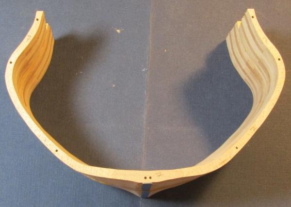
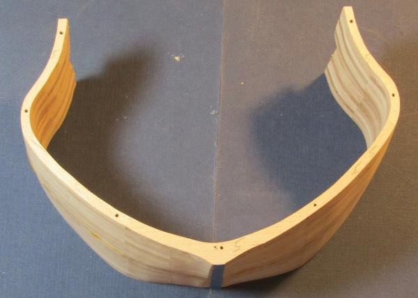
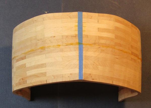
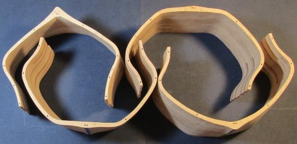
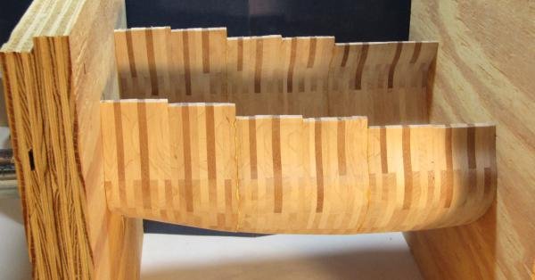
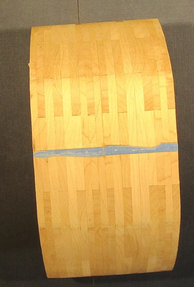
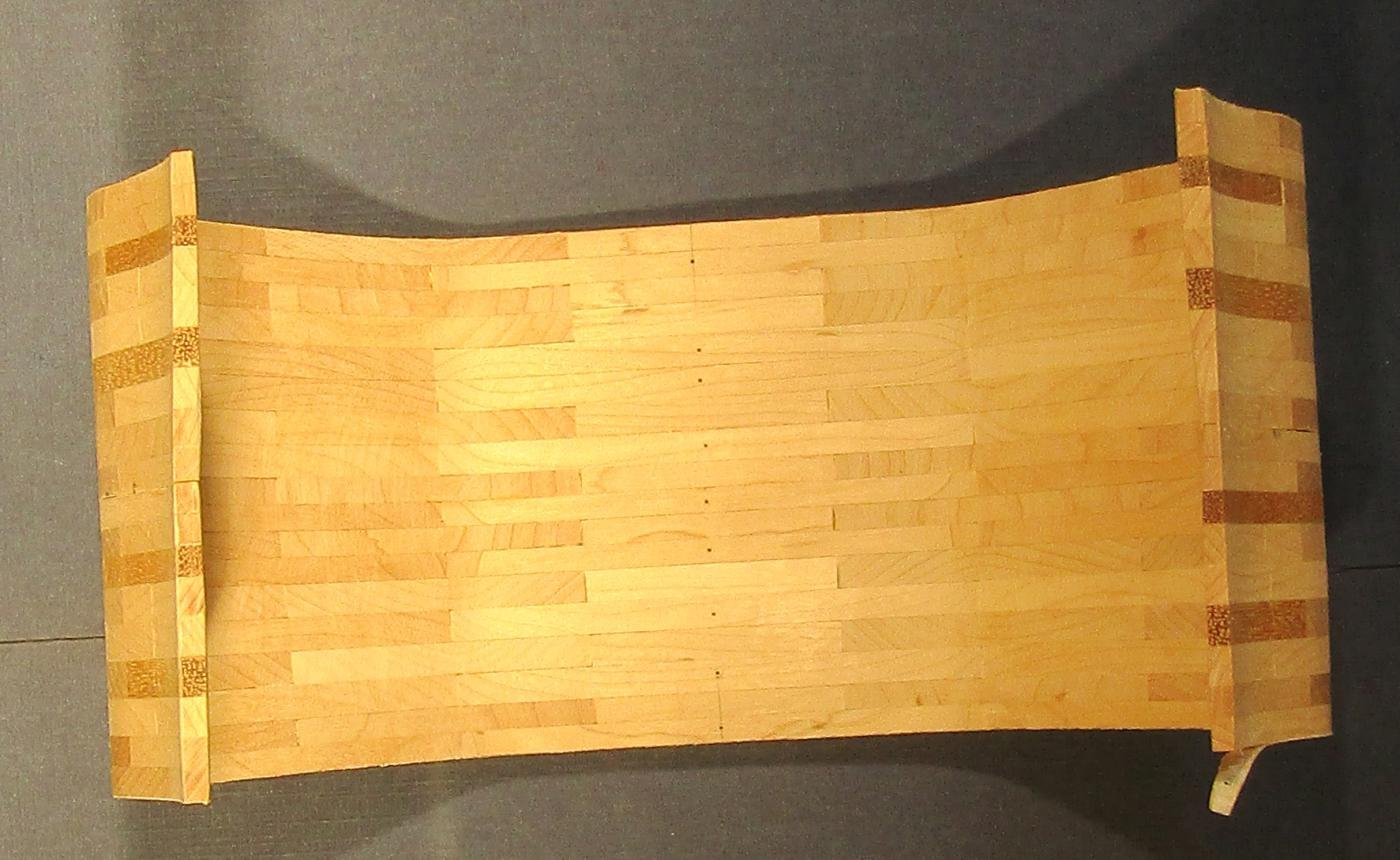
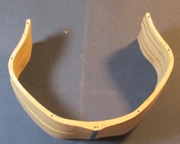
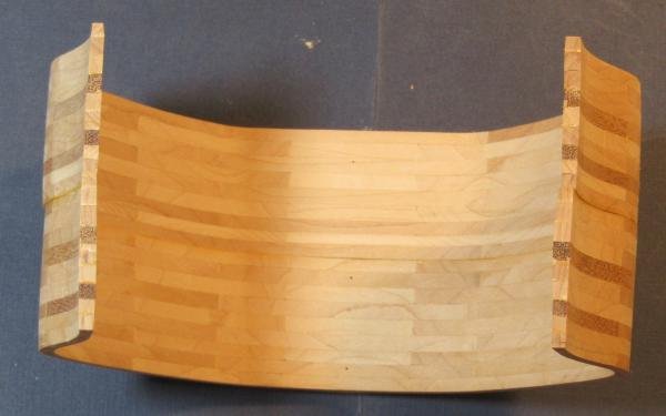
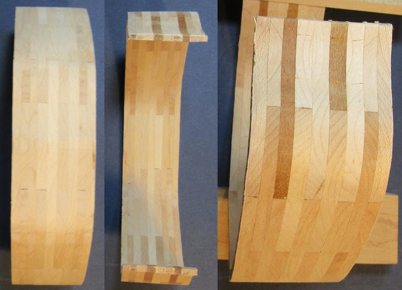
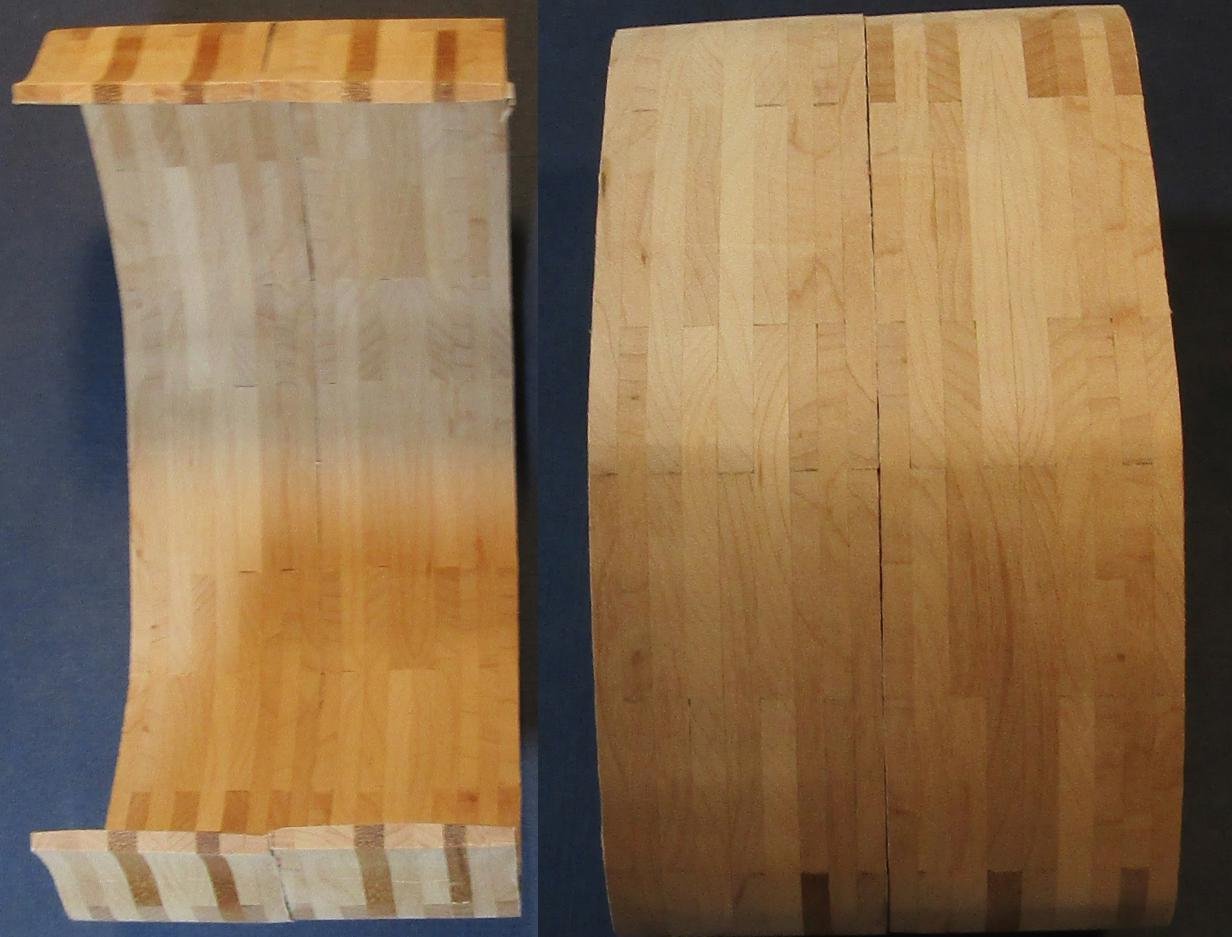
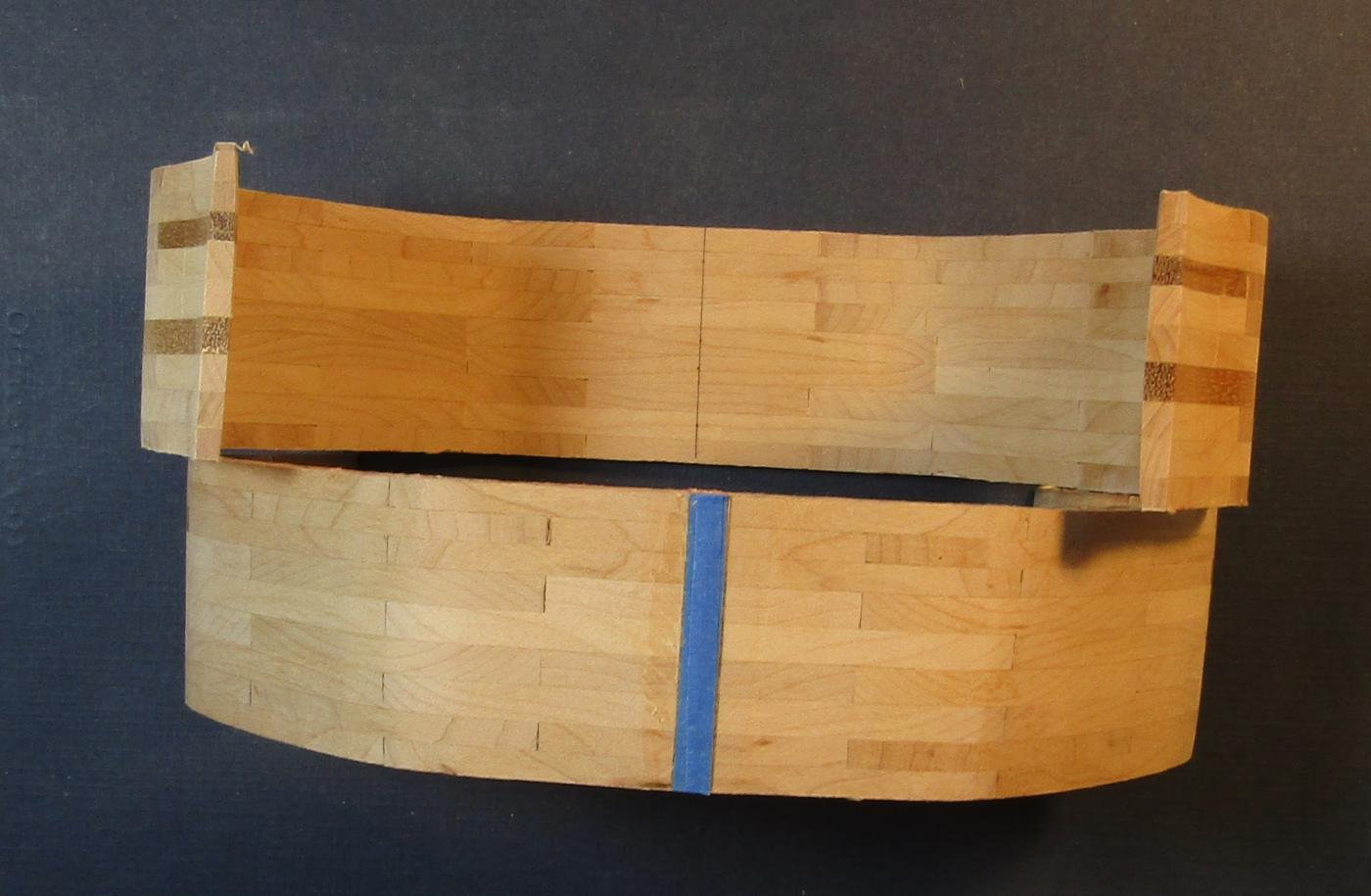
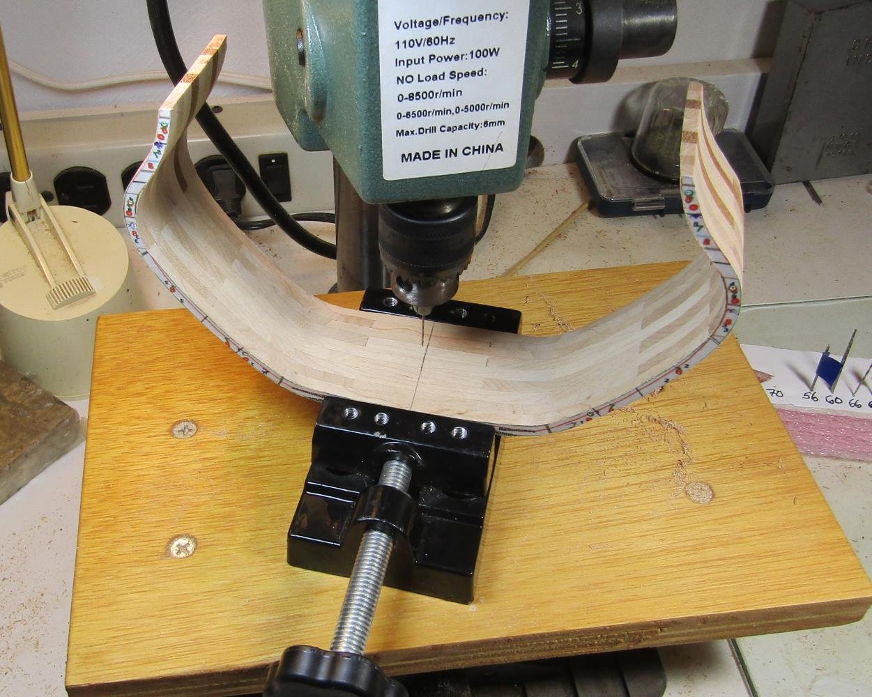
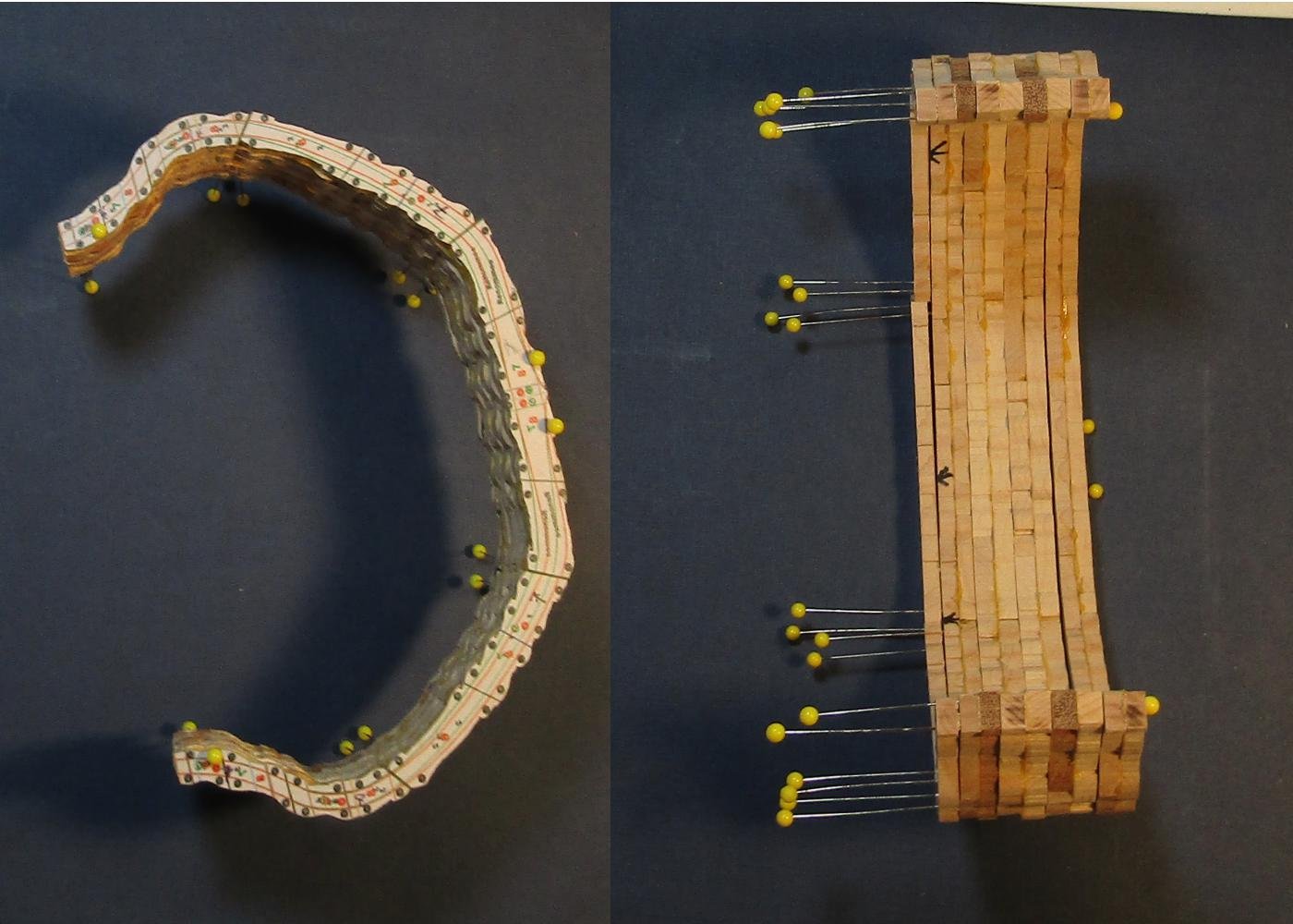
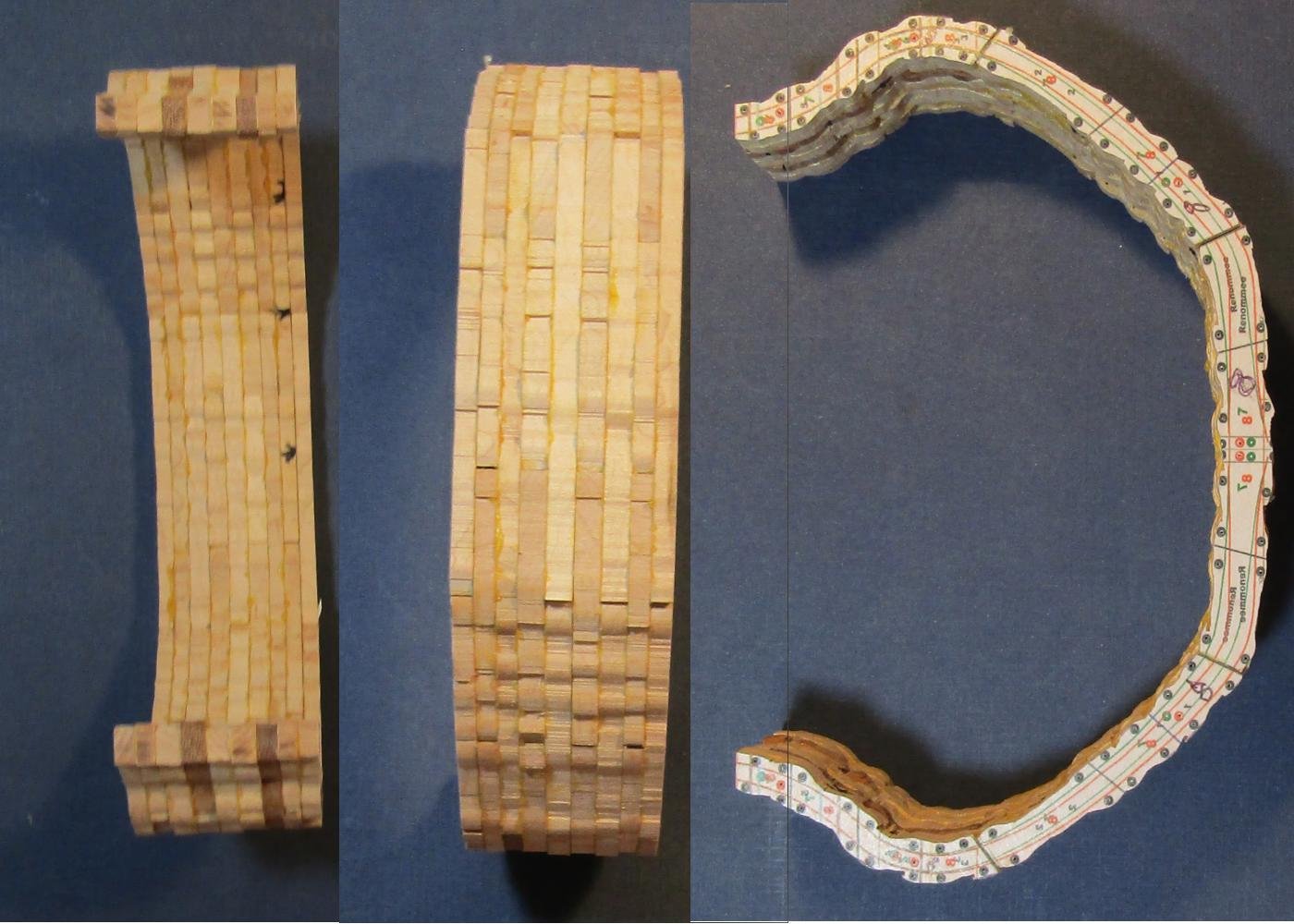
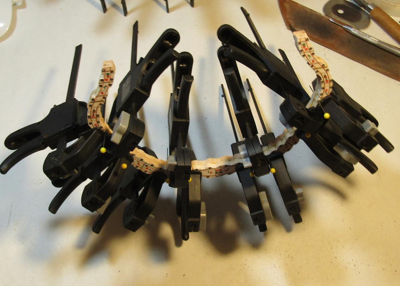
This is the final shape of this station sandwich. The near red ochre of the Elm at the sides of the gunport contrasts against the Maple. This represents the shaping of 8 frames/4 bends at one time. Any more shaping will be to transition to the next sandwich, when they are joined on the faces. La Renommee has an elegant shape in her cross section. I now have to repeat this process 15 more times to produce the complete hull, less the stern framing and hawse timbers at the bow. Station VIII side Station VII side Station IX-VIII has been shaped and is dry fit to Station VIII-VII In the process of dry fitting and deciding how to mark the deck and wale locations once the pattern is removed ( a knife cut ), I recognized that the keel location needed.work. I drew the center line on the inside and placed tape to protect the keel site. When the hull is shaped as a single unit this location is subject to erosion. The line on the inside will not survive any sanding. I drilled a #70 hole in the center of every floor timber. Although it was too late for these first two frame sandwiches, The center line hole will be drilled in the individual floor timbers before any assembly with the rest. Stations IX-VIII and VIII-VII have patterns removed, faces sanded and locator holes sized to be an easy fit for the 8 dowels. My frame press helps get a strong bond. Difficult experience has taught me to measure the thickness of a sandwich unit at the rail and the keel. It has also taught me to assemble the hull from mid ship towards each end. I do shaping at the glue joint with the addition of each new unit of frames. With each sandwich addition the whole becomes progressively more difficult to manipulate and the interior more restricted as the hull builds out. I ease this task by doing a smaller sub assembly of sandwich pairs. I like the clamping pressure that my frame press generates. The press will only open enough to accept pairs of sandwiches. If there is a problem with station thickness being different between the rail and keel, each sub assembly will be adjusted if the keel is not flat when the rail faces meet.
-
I have no recommendations for your choice of kit. From the ones that you have chosen to collect, none appear to be all that difficult. No liners or large frigates, so you are not trying to learn on a subject that would tax anyone, experience or not. I commend you for that bit of wisdom. Were you venturing into scratch, first, for milling, irrespective of dust collection equipment, you would want to do it in an out building. The same for shaping with a belt or drum sander, they throw too much dust for a living area. Ideal, for me for the big guns, a hole on the wall with a clothes dryer or cooking hood outside fixture - but more insulation. Attach that to a hose venting a Rigid 14 gal. shop vac in a sound baffle box ( it is not all that loud, compared to older model shop vacs, but being able to hear music while it is on is nice ). a quality RIF remote ON/OFF switch. Intermediate - something like a Dust Deputy cyclone trap - easier to dump and saves having to clear the vac filter so often. For in the house, a smaller size portable canister vacuum - the kind that is easier to clean stairs with - bagless is good. For a spray booth, I do not see why a large corrugated cardboard box - you can strengthen it by PVA gluing more layers of cardboard onto it A furnace filter at the back and a hose connection for the canister vac hose. LED strips are light weight and generate relatively little heat = inside the box.
-
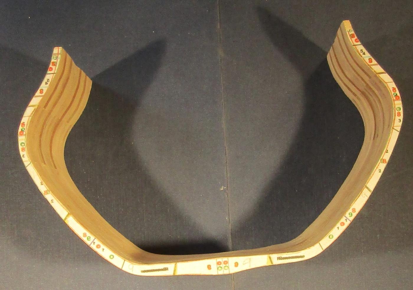
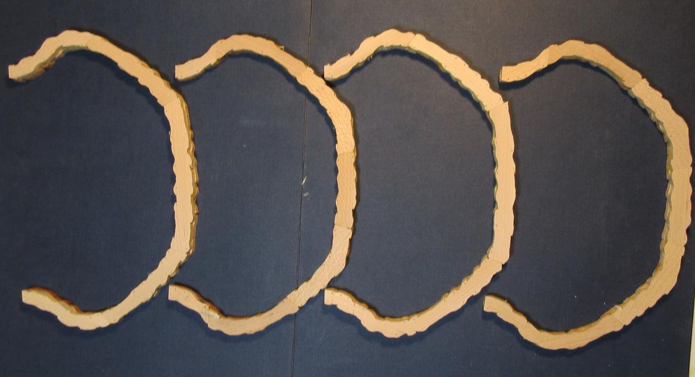
Four bends sanded and ready for assembly. Dry fitting the 4 bends and 9th frame. Note the four Elm tops in the interior. The bends are then glued into the sandwich, using the same pin holes. No more than 4 pins are needed to align the bends. Prior gluing the bends leaves dry glue in the pin channels. The selected alignment holes need a careful re-drilling with a #70 bit. PVA is used on the bonding surfaces everywhere but at the sides of the gunport opening. I use Scotch Permanent Double Sided tape there.. When the glue has set, the sandwich is ready for shaping. To save a step I also glue the 9th frame along with the 4 bends. I have to pay attention to the timber seams to assure the shape lines up. This is a target during shaping. The glue cured, the station sandwich is ready to be sanded to its final shape. This is VIII-VII / 8-7. The pattern is identical on either side. On the face showing (8), the target outline is red. The interior locator points have been drilled thru the outer frame. I remove the bulk of wood using a 4x36 belt sander, except where the curves do not allow it. The grit is 60 or 80. I bought silicon carbide belts before I read that Al oxide open coat is the better medium for wood. The sandwich is on the table just for the photo. I free hand the piece while sanding. I finish the rough shaping on my drum sander. That is 60 grit on the very handy 6" drum. This sandwich needed to see a 1.5" and 1" diameter drum to sand the inside curves. The final work is done using 220 grit paper. It takes longer, but I like that because of the hardness of Hard Maple, it takes more effort to over sand when dressing to the line. I prefer the added resistance that the hardness provides. This is the stressful step in this method . A serious mistake means the lose of 8 frames. The pear billet is there for posing.
-
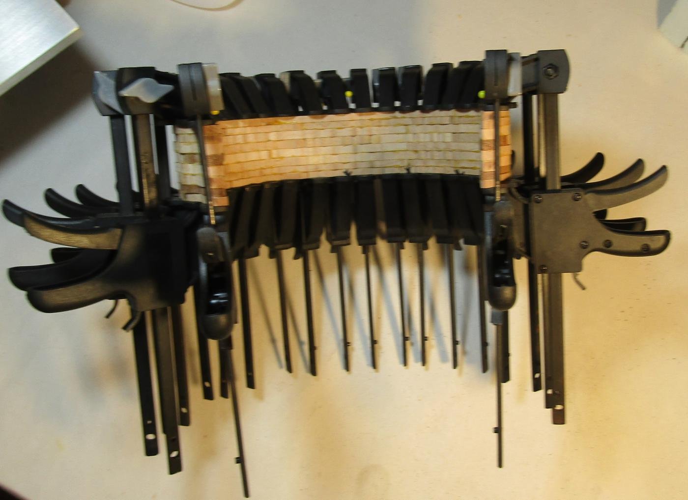
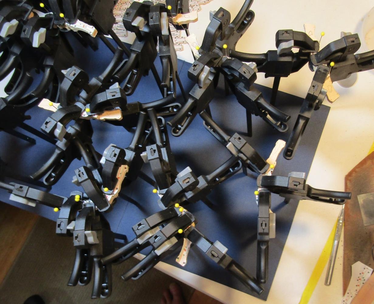
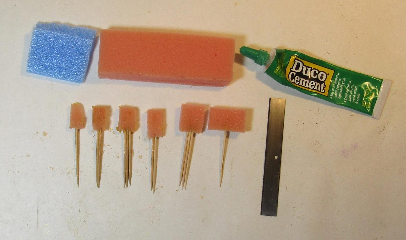
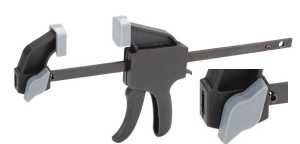
I assemble each bend in two stages. For the first stage, overlapping pairs of timbers are glued together. This adds an additional day to the process to give time for the gkue bond to cure. Assembly is easier when done in stages. The glue up of the bends is done using yellow PVA (Titebond II). I totally wet both surfaces with a thin coat of glue * With PVA, strong clamping pressure yields a stronger bond * A series of custom made applicators help me make an efficient coat of glue. They are cut from packing foam in useful shapes and thicknesses. I use round tooth picks for a handle. Duco quickly bonds the toothpicks to the foam without melting it and the bond is not affected by water based glue or water. (Duco is not good for much, but it works for this. The foam sticks can be washed and reused.) * For clamping I use Pittsburgh® 4 in. Ratcheting Bar Clamp/Spreaders, a Harbor Freight product, but only the model with the large grey wing nut. Every other model that I have tried has been a total failure: Irwin, MM, Widget Supply, Pittsburgh® with a small wing nut, all are a waste of money. I can get more clamps on a job if I remove the pads on the jaws. If a clamp spins its wheels when clamping, giving the rod a scrubbing with corse sandpaper gives a better grip. I use a lot of these clamps at this stage. I am now up to about 150 of them. It is fortunate that I could get a lot of them for $1 each during an in store sale. I now do a procedure to assist in later opening the gunports. A cut is made along the sill line and lintel line in the bend that contains the gunport, about 3/4 deep. There is a ways to go before I find out if this really works for cutting out the gunports. Except for the frames at each face of the sandwich, the patterns are now removed. The partially glued segments are assembled into a bend. The faces of the bends are treated to a sanding using a full sheet of sandpaper on a piece of plate glass. With POF, it is helpful to have a large absolutely flat glass surface, for gluing and parts assembly. A glass company made two 12"x18" sheets of thick safety glass and beveled ground all of the edges. They have been well worth the expense. They do make packing up your shop for a move interesting. There are two faces that must not have the patterns removed - the two outside faces. Once the bends are bonded into their sandwich and the sandwich is shaped, then the fore and aft faces have the patterns removed and they are sanded.
-
For temporary and down and dirty way to avoid having to go thru the cleaning process in the future: Make a wire frame - using wire that is at least as thick as what the old style wire clothes hangers were made from. Cover it with clear plastic - 4 mil or 6 mil vapor barrier would be ideal, but clear plastic food wrap would work. When you wish to show the model off, just remove the cage. It may be ugly, but it seems to me that most anything is better than having to do the conservator cleaning thing.
-
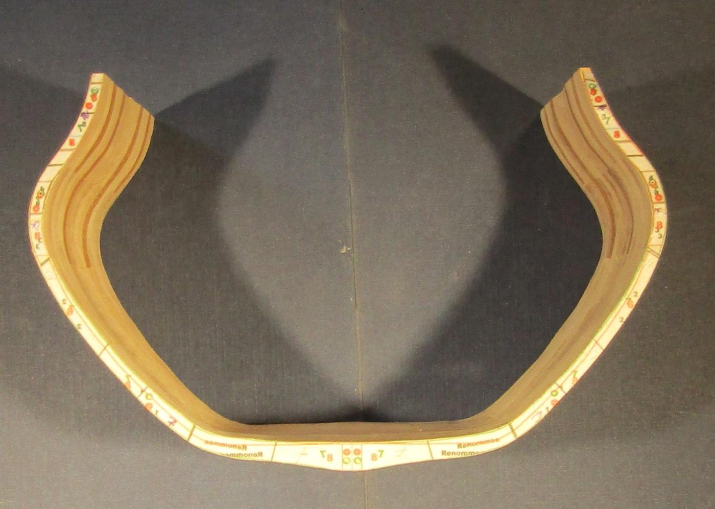
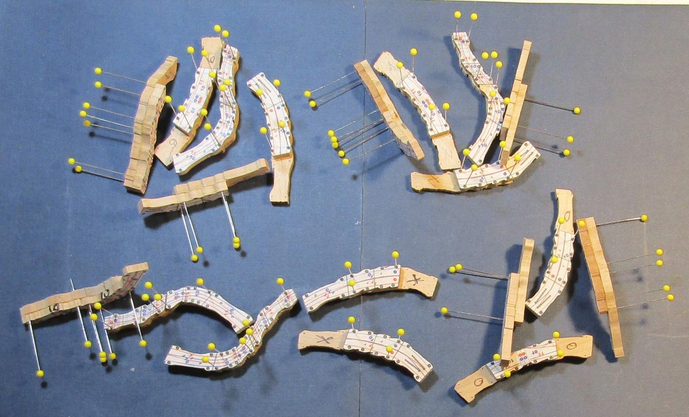
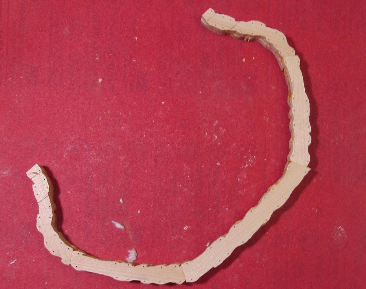
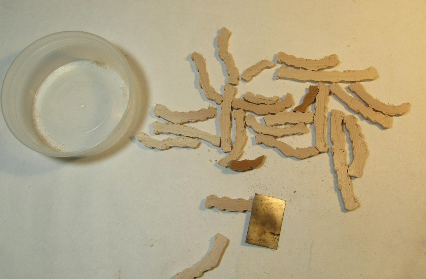
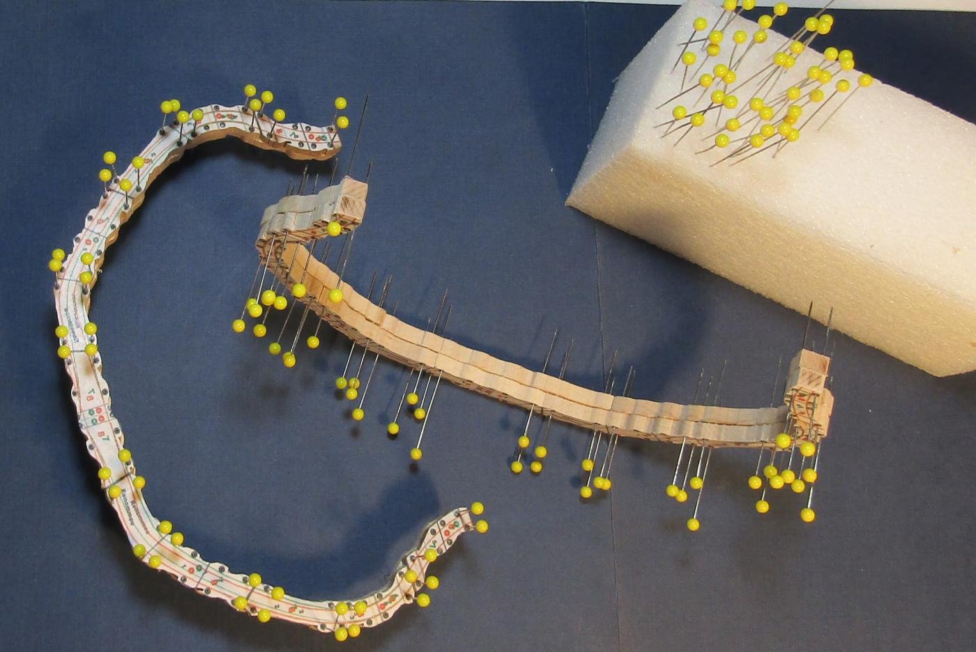
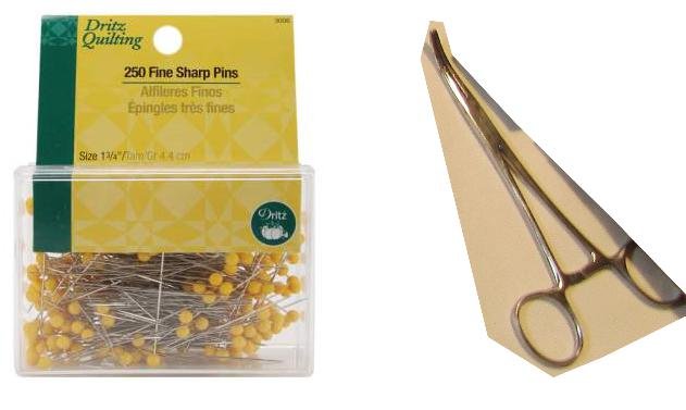
The timbers. These pieces of wood are the timbers for the two 0.21" bends for VIII-VII. The band saw leaves fuzz at the bottom edge of the cut. I use a small thin scraper to remove it. The edges of the timber pieces are well away from the final edge, so a bevel on the edge is OK. The butt joint lines are carefully sanded. I use a butt line that is a little thicker than it could be. A razor thin line sanded to almost gone, runs the danger of complete removal and then there is no indication if I may have even gone farther. It usually works for me to sand until the white spots in the black at the outer edge are gone. The bends are dry fit. If a joint is too tight, the piece is returned to the disk sander. The timbers are aligned using 1 3/4" quilters pins. These pins are #73 wire gauge and a #70 hole in the wood allows the pins to be pulled out after gluing but has no significant play. The pin removal can get interesting if I do it after the glue has set. The locator dowel sites are drilled thru the timbers of the frames at each face, using a #50 bit. The hole is only one frame thick. The degree of bevel becomes enough much beyond the dead flat that a hole thru the middle of one can exist the outer face of the next timber. This process uses a lot of pins at this point. They are easily bent when withdrawn and the glass head can come off. 250 pins soon becomes not nearly enough. A curved hemostat aids removal. A really stuck pin needs 2 clamps and a needle holder to rotate it to break the bond.
.jpg.5c2fee747ad18f94fa8d345af31a30a1.jpg)
-
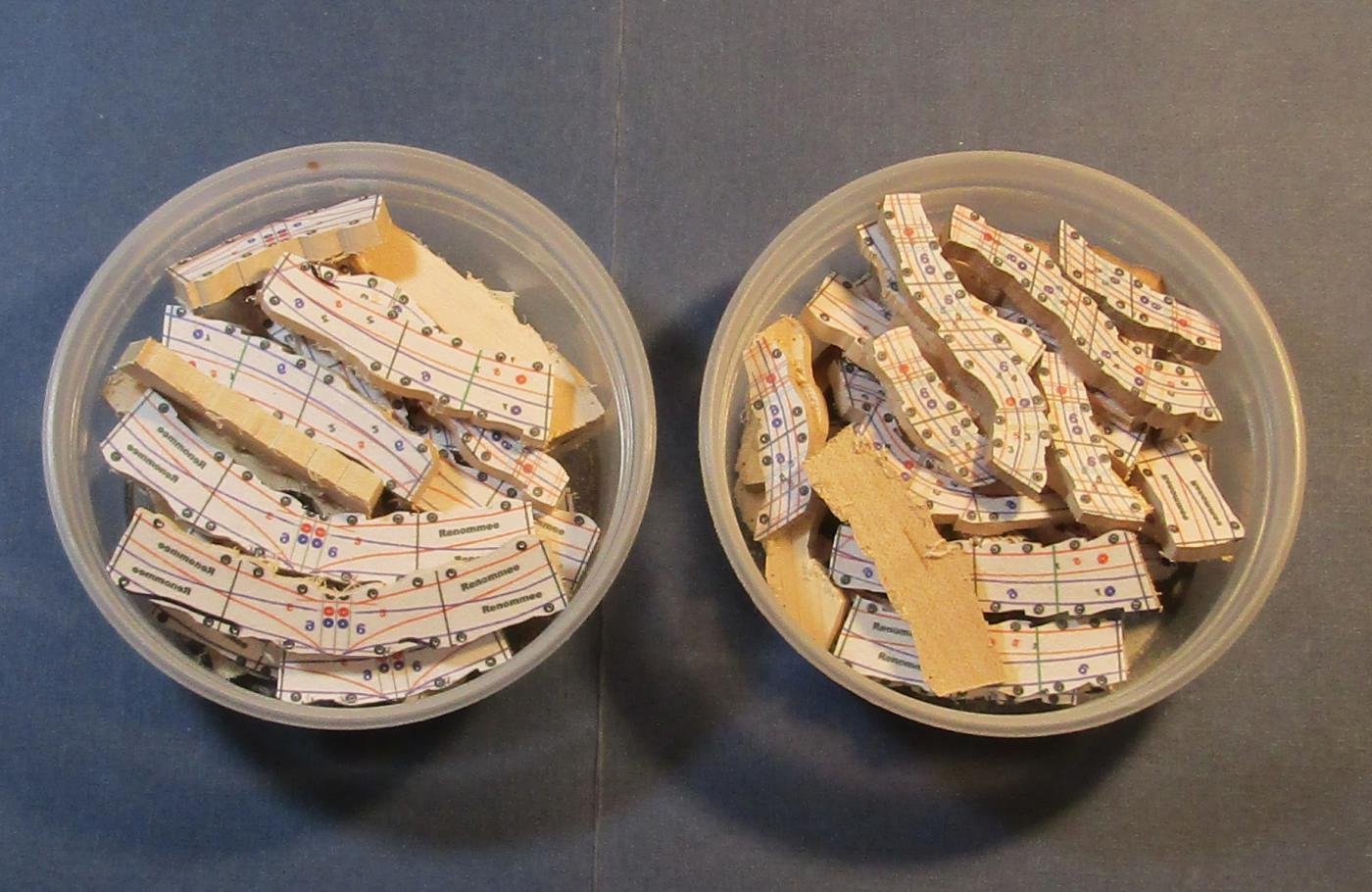
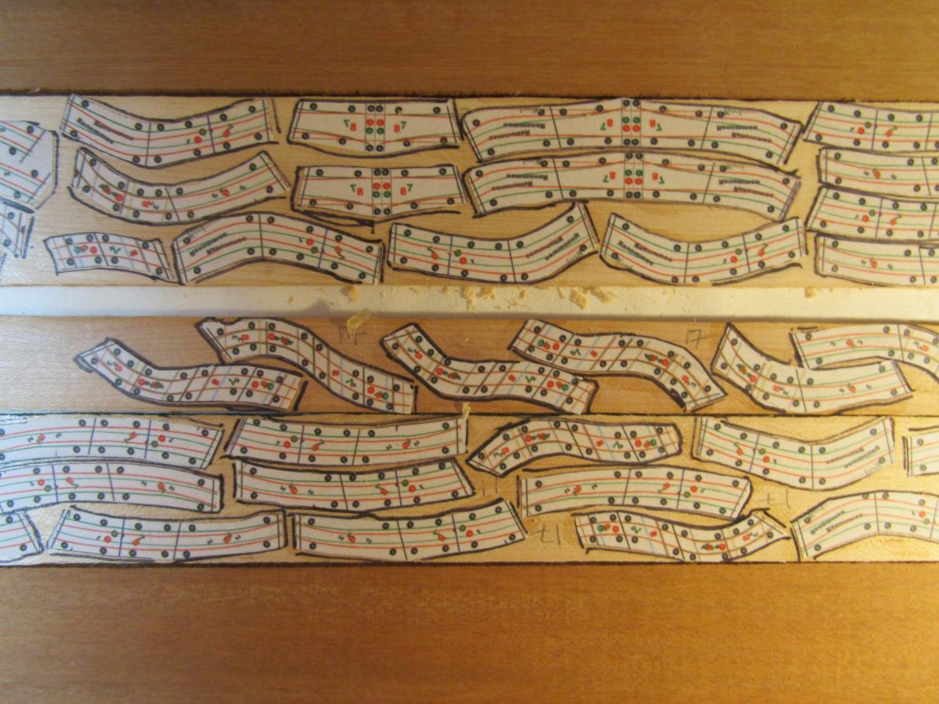
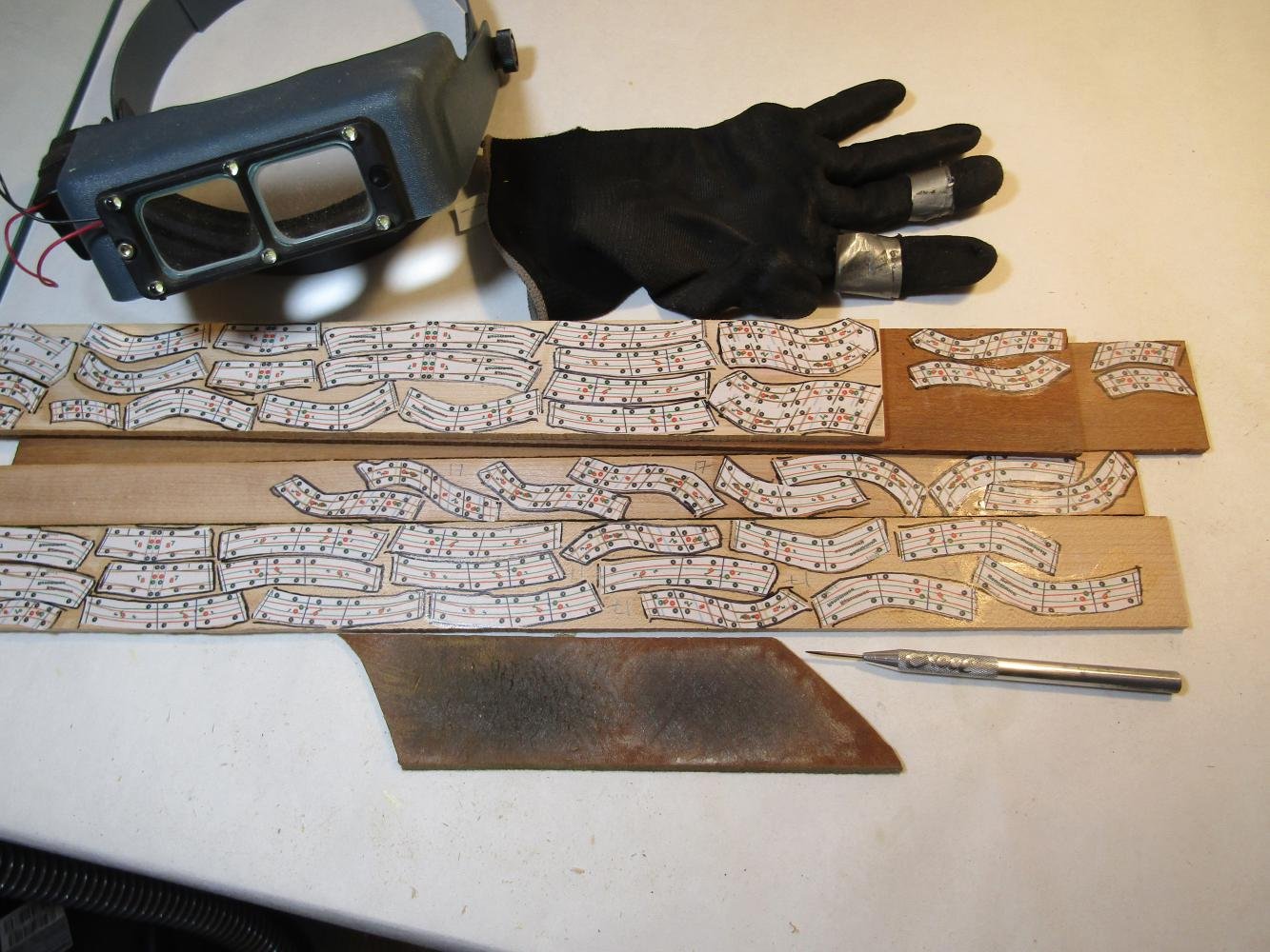
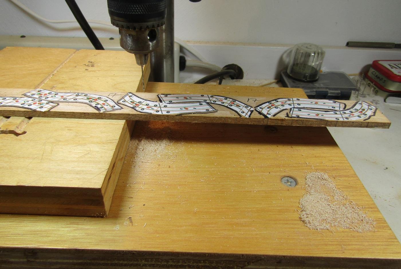
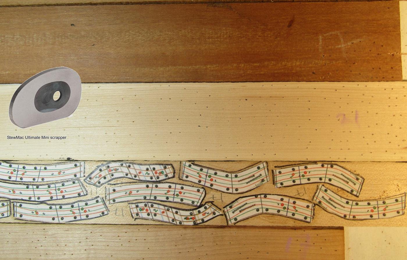
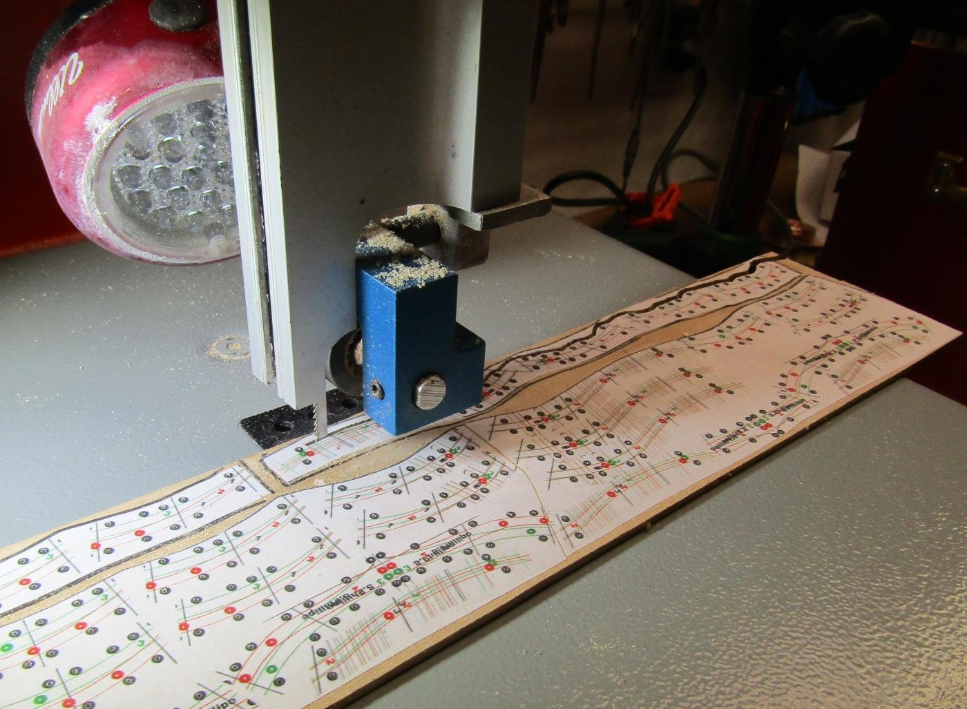
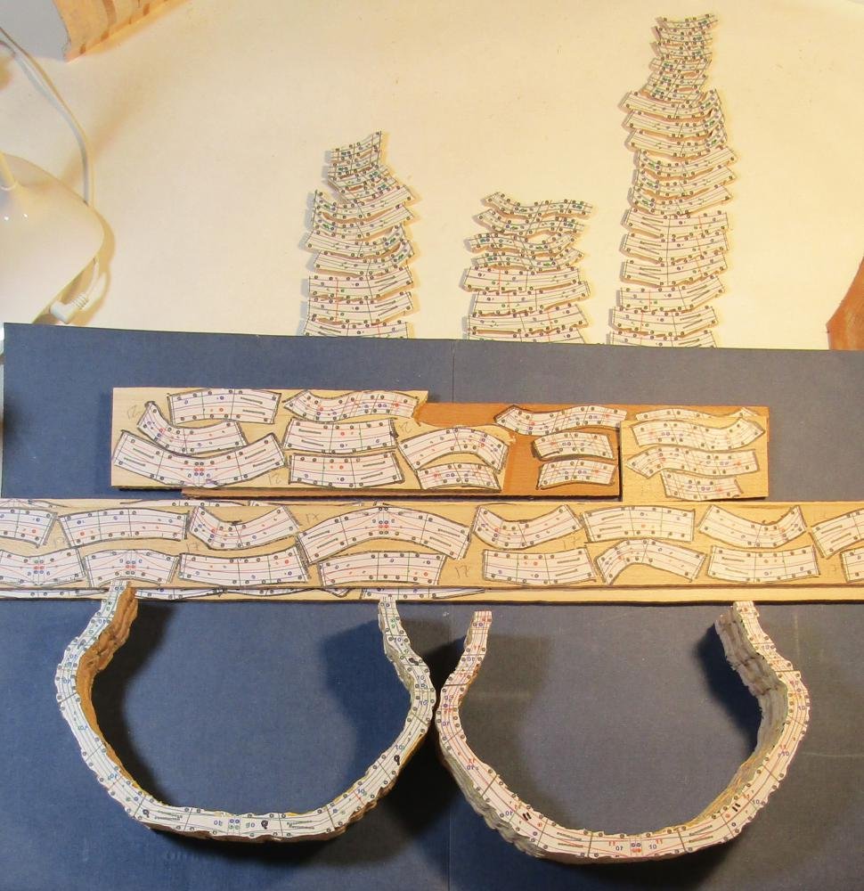
Starting with the first sandwich forward of the mid ship station (VIII-VII): I cut out the individual timber patterns, inventory them, and place them on my Maple stock. I try to arrange them to reduce waste and still leave room for the scroll cut kerf. The locations are outlined using a fine black Sharpe. The patterns are flipped N/S and placed in a mirrored location on a piece of wax paper. Both the patterns and the outlined spaces on the stock receive a heavy and complete coat of rubber cement *. When the cement is dry, I use tweezers to place the patterns. Double coating and applying when dry does not allow for easy adjustment when positioning the pattern. The outline helps my aim. * Best Test cement has worked well for me. I use the solvent (Bestine) to keep the cement at an easy brushing consistency. The double coat, then dry adhesion method is for a stronger and longer lasting bond. A pair of quality needle point tweezers for placing the cement coated patterns is worth the investment. Rotating the wax paper 180 degrees makes for an easier E/W wrist rotation during placement. Reusing the wax paper builds up a layer cement. This holds the patterns in place while I brush on the cement. The lacquer coat protects the pattern when peeling it off of the wax paper. I use a needle point awl to punch a starting hole in each of the OutPin and InPin locations on the cemented patterns *. * I strop the awl frequently to keep the point sharp. A glove with a reinforced finger tip avoids developing a blister - lots of holes to punch. The hole that I drill is #70 and the bit wants to dance over the surface. I use a magnifier visor to see where to site the awl point. I find that using the drill press without the hole as a guide is difficult and prone to error because my view is somewhat obstructed by the drill press. The gloves became too much of a bother. I added a bump using electrical tape. No blister, less fatigue. The pin holes are then drilled using a drill press *. * An economy Eurotool DRL 300 drill press has worked well for me. A precise vertical hole is required. Hand drilling is too open to error. I set the bit in the punched hole and then start the drill rotation. A momentary foot switch saves having to have three hands - one to hold the stock, one to lower the quill, and one to flip the switch. A Harbor Freight economy foot switch has been enough. I fixed the switch to the board where I rest my heel. I upgraded the drill press by adding an XY table and clamping on a 3/4" Birch ply top. Due to the number of holes to be drilled the XY is of no help. The cliff edge of the loose board is enough clearance. The drill bit leaves fuzz on the underside. I use a scrapper to clean it up. The fat StewMac is my favorite for doing it - now. The individual timbers are scroll cut from the stock. I use a generic 9" bench top band saw with a 1/8" blade *. I do nor care for the work piece chatter with a scroll saw. This 0.21" thick Maple is work enough for the saw. A more powerful motor is something that I would like when cutting dense wood that is thick. * I was able to adapt a Carter Blade Stabilizer to my saw. It replaces the upper and lower support guides that hold the blade in a fixed position. With the stabilizer the back of the blade rides in a grove on a ball bearing. The blade can swing as though hinged at the back. It allows for a tight cutting radius.


-
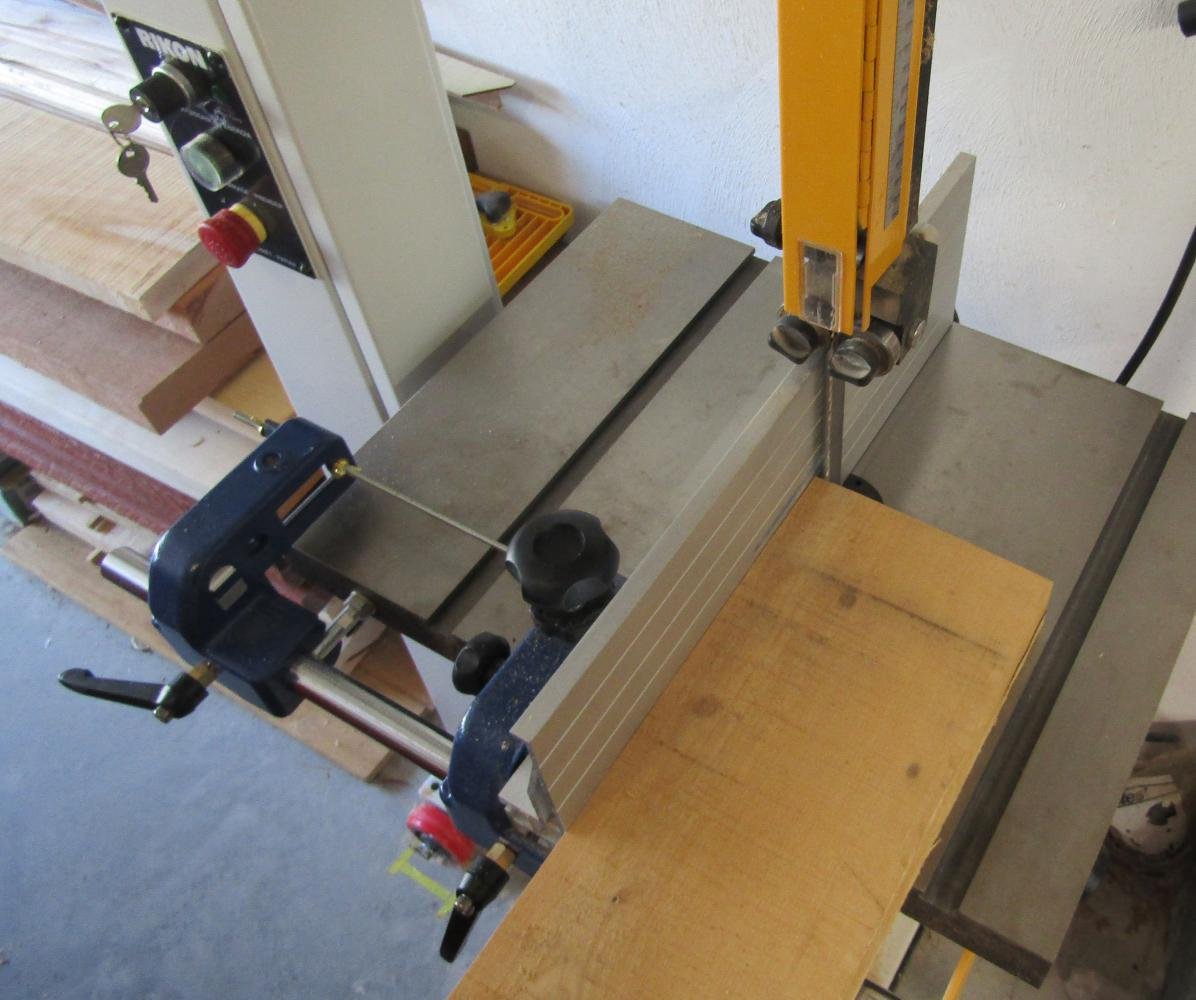
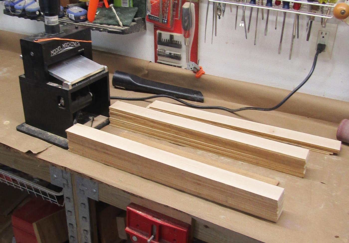
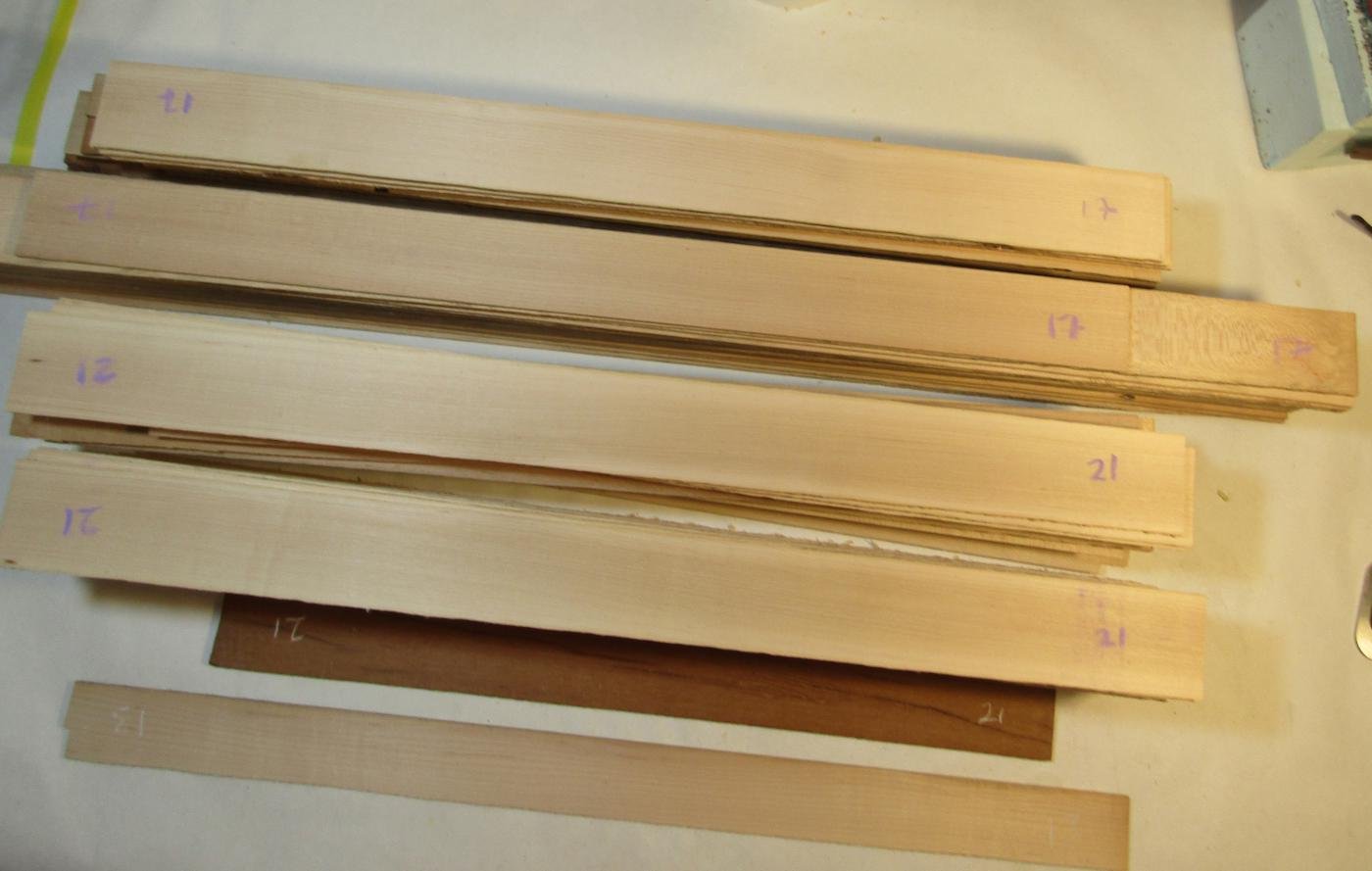
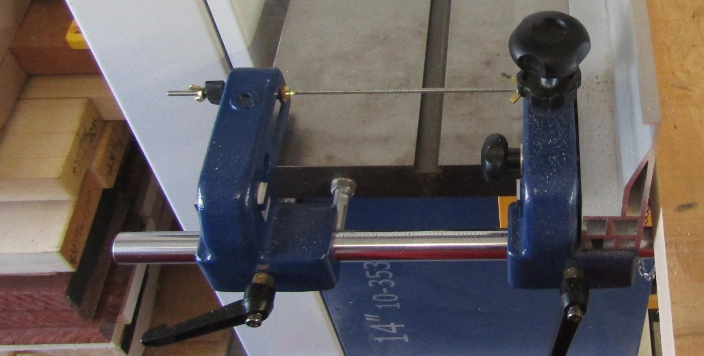
This catches this project up to the stage where the building part of the log will begin. The assembly of frames began on Oct. 29, 2019. The lofted patterns being ready for use, my next step is preparing a stock of wood. I am doing this build as a solid wall below the load waterline as well as above it. Unlike the situation were this for POF, I will need no Pine for temporary space fillers or separate patterns for fillers. I will use Hard Maple - Acer saccharum - for all layers except the top timbers that frame the gunports. Hard Maple is a much stronger and more dense wood than needed for this. I like working with it and I can source it locally at Yukon Lumber at a reasonable cost. Its hardness makes for more work to shape it, but it also makes it difficult inadvertently remove too much. For the port frames, I will use a red wood that I think is Rock Elm. I bought a plank of red wood that I thought was aged Black Cherry from a local picker on Craigslist. He sourced it from an attic at an estate sale. It is not Cherry, being very hard and showing a different grain. The $2 /BF savings turned out not to be a bargain after all. I use raw 8x4 lumber. By not having it planed, I have an actual 2 inches of thickness. Overall a 2 foot working length is the sweet spot for me. The assembly plan for the sandwich has it that matching the thickness of the layers to frame the ports requires two different thicknesses of frame stock: 10" and 12.5" . (Except for station sandwiches IV-III and X-IX, which require an 8" layer to match their gunport locations.) This is 0.13", 0.17", and 0.21" stock at a scale of 1:60. Although no surfaces will be on display, having no open frames, I still will still use stock finished sanded using a 220 grit material. I use 80 grit to remove the surface scars and get close and 150 grit to fine tune. This is the processed supply that I estimated to be enough for this hull. * Band saw tips: A band saw blade for wood has teeth with set. This leaves scars on the surface. To save wood and reduce the number of cycles I try to cut each plank to a thickness that requires very few additional passes to get the target thickness once the plank is sanded smooth. An additional thickness of 0.04-0.05 inches is needed to get a smooth surface on both sides of a plank after sanding with my present set up. I find it difficult to micro adjust a band saw fence. The fence is locked by tightening a bolt. The bolt rotation moves the fence after it has been set. It is difficult and frustrating to find a fence position that becomes the one that I want after the final movement due to locking. I decided to try adding a micro adjustment device that was fixed to the fence and that adjusted against a fixed anchor. A threaded rod has a known distance per rotation. The carrier assembly that connects the fence to the table is a separate component that allows for adjustment for drift and to rotate the fence from vertical to horizontal. It has holes in the right place to hold a threaded rod. I ordered a second carrier assembly for my fence. It is always locked and is connected to the fence using the threaded rod. The free moving fence can be micro adjusted by rotating wing nuts on both sides of the second clamp. This also keeps the locking bolt from moving the fence when it is tightened. A powerful motor is an important feature to consider when choosing a band saw. Cutting 60 or more 2" by 2 feet planks from billets is probably more cutting passes than non-professional woodworkers subject a saw to in a short period of time. Steel blades have a short life under this sort of use. They get dull and break. Once dull, it does not matter if they break, because the blades are not able to be resharpened. A carbide tipped blade will last much longer than just steel. A steel blade with thin kerf and minimum set is $20 -$30 each. An economy blade has too much set and the wider kerf and additional time at a thickness sander to remove its scars negates any imagined savings. A carbide blade is $200. It lasts enough longer than steel to make it still the less expensive option. There is an even better third option. A bi-metal wood blade is $60. It does not last quite as long as a carbide blade, but a carbide blade does not last 3 times longer than the bi-metal. I think the real economy is with the bi-metal blade. Back to the build. Here is a preview of where I start.
-
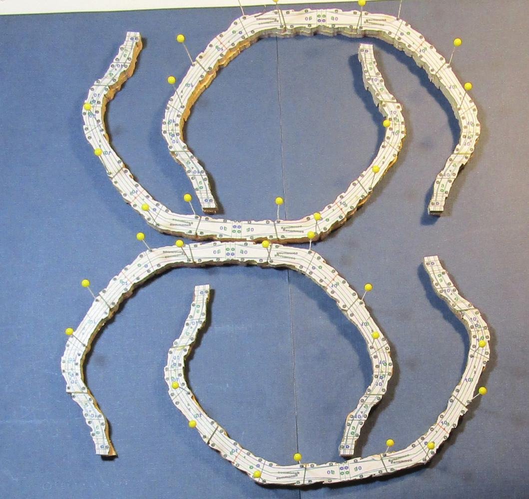
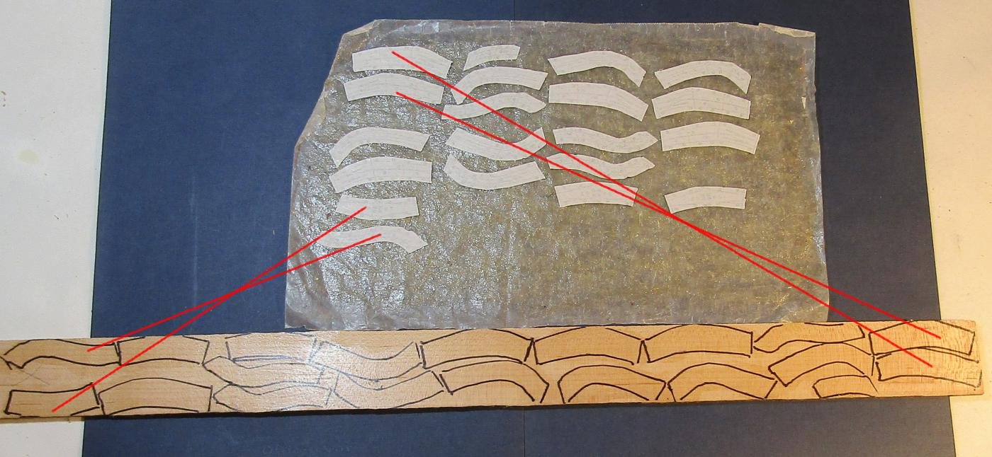
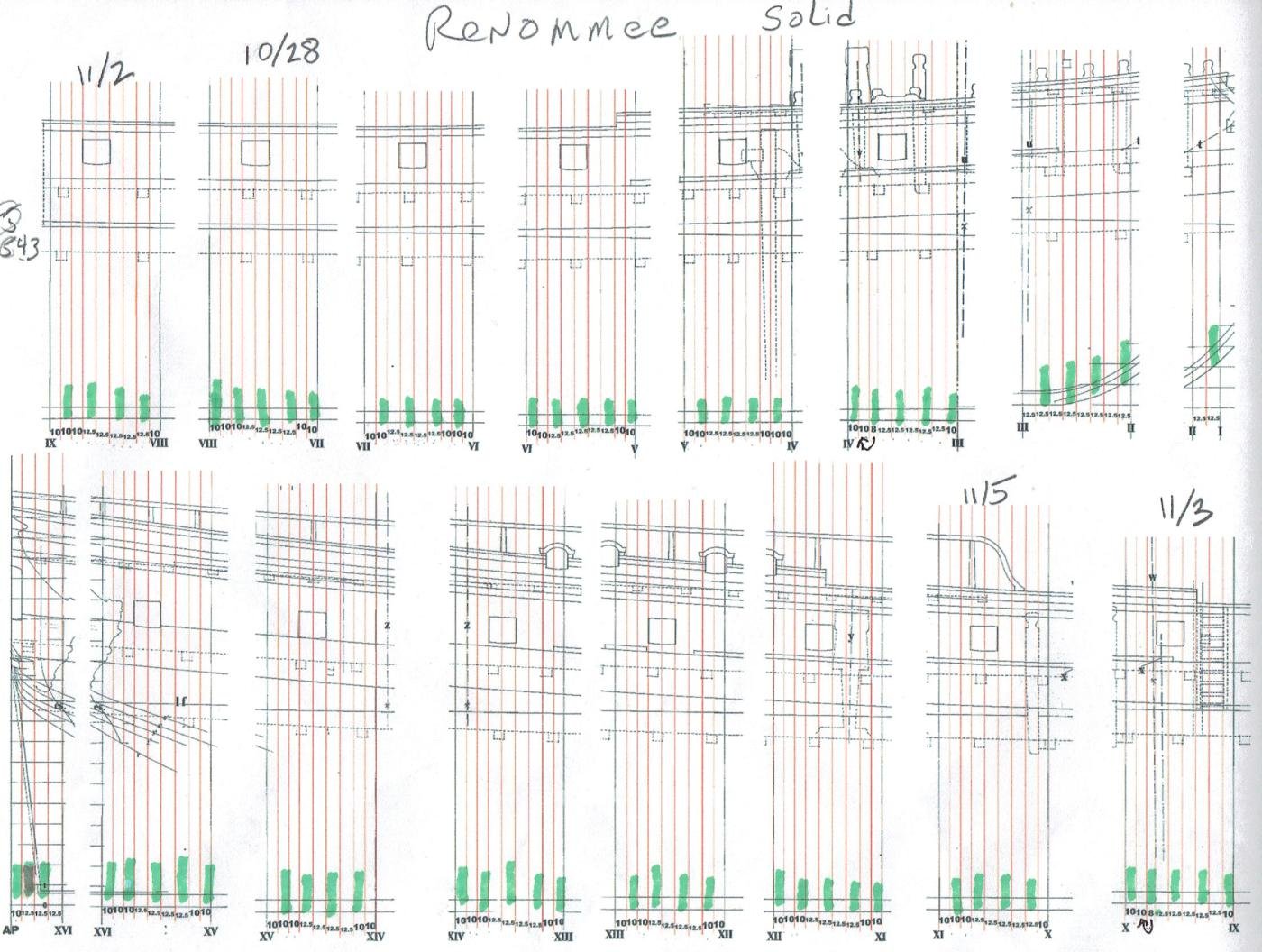
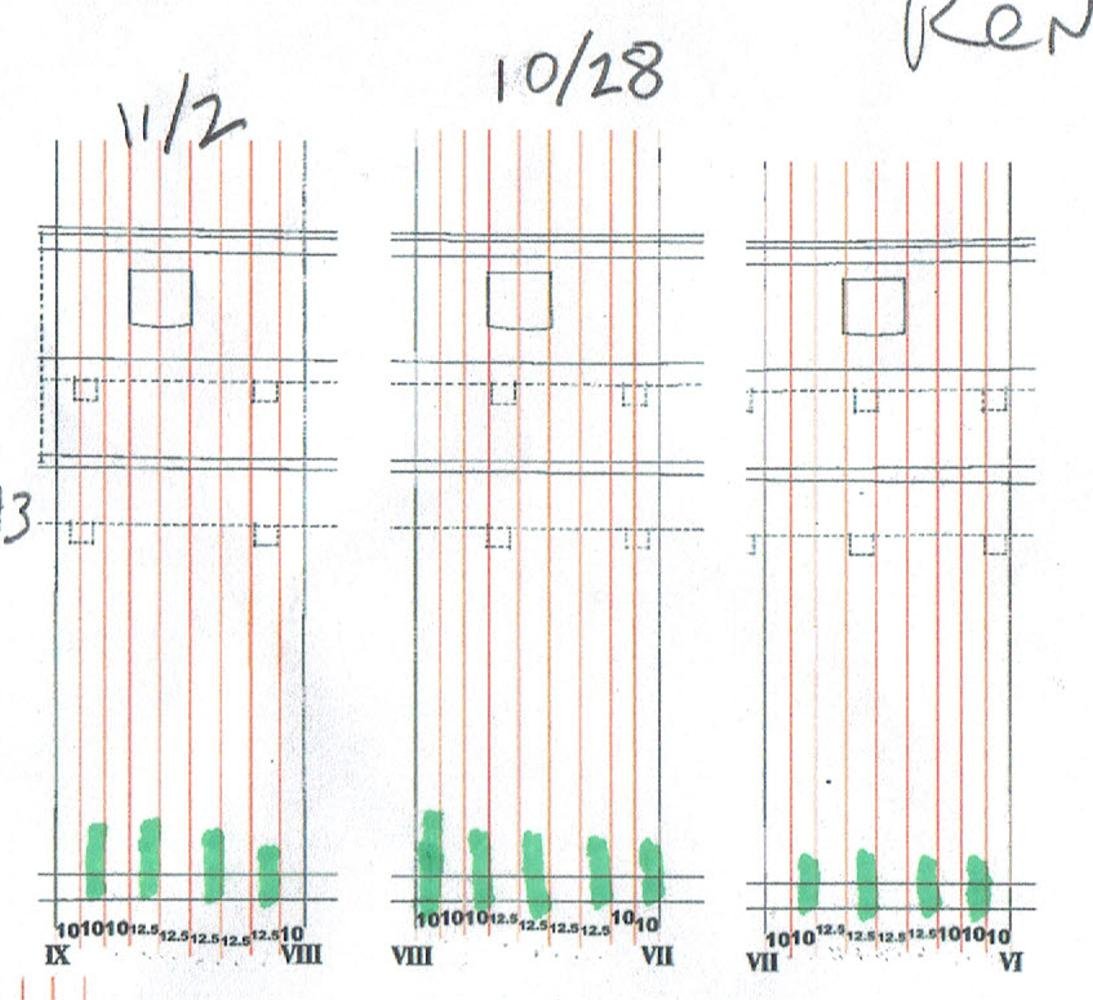
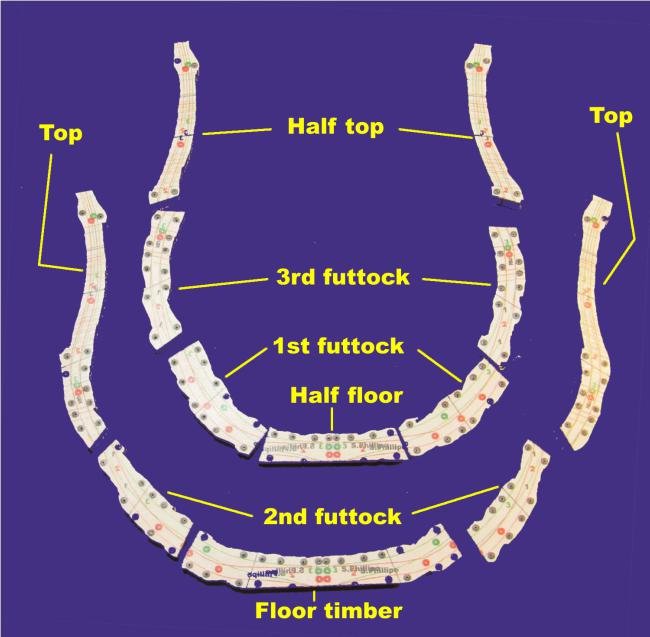
photo_12 I only use the left side of the full frame to get the shape of the floors. These along with the timbers for the right side are selected and positioned on a new page. My frame stock is 2" wide boards. The right side timbers are closely positioned in a 2" by 1 foot area. This allows me to estimate how much wood that I will need. photo_13 The group of timbers is then duplicated. This duplicate is flipped vertically to get the mirrored left side. photo_14 Then the pair of groups is duplicated and moved to fill the page. photo_15 To protect the patterns from dirt and humidity, to stiffen them, and to ease their removal when no longer needed, I give the sheet of patterns a liberal coat of brushing lacquer. I do not spray it because I do not wish to breath it. photo_16 The plan for the frame assembly. It is as much information as I need to assemble the hull. photo_17 This is a plan for the first three Station Sandwiches. The green bars are the floor timbers. The thickness of each layer is at the bottom. The option that I am using to frame this hull will have no spaces. For this model of La Renommee the sided dimension of the timbers will not be that of the original as presented by Boudriot. It will be the sum of thicknesses to equal the distance between the stations. This build will include an experiment. Locating and cutting gunports can be a difficult chore. I have positioned the layers and set their thickness so that the sides of the gunports are exactly formed by the timbers on either side. The opening will be partially cut during frame assembly. The frames at the sides of the opening will be bonded with tape rather than PVA. Retaining a temporary timber filler will protect the edges of the ports during shaping. This produces an odd number of frames in each sandwich. The location of the floor timbers is different for sequential sections. It requires closer attention than normal POF where the sequence is regular. I originally lofted this ship for POF with visible framing. The intersecting line in the middle of futtock 1 is a butt for the space filling wood. Using a single piece wastes too much wood. With POF, the frames at either face of a sandwich are single frames. They become part of a bend when two sandwiches are bonded. It is difficult to keep single frame timbers in position when the filler next to it has a butt at the same location as two of the timbers. Had I chosen to follow the plans for La Renommee in the monograph and build the huff POF, the layout would have been 2/3rds timber and 1/3rd space - two 8.5" frames and a 8.5" space. This is how it is on the monograph plans. The POF options possible with this method: I could have also followed a different framing style: 1). Hahn style with the timbers widened to include the space and dropping every other bend = two 12.5" frames and a 25" space. Wide timbers and wide spaces. 2). Naval Timber framing - 12.5" frame and a 12.5" interconnecting naval timber. Open spaces are below and above the naval timber. The start of the filling wood above the LWL is determined by the desired visual effect. This is a very stylized version of the framing done at the time of Mary Rose. 3). Navy Board framing - out of respect for the founders of our craft, I find 1744 is too late in time for this style to be appropriate for a model. ( The lengths of the floor timbers, futtock 1 and futtock 2 needed to execute this style makes it expensive and wasteful of wood at the larger scales. ) By not choosing any of these options, I will not need the lofted timber shapes for the temporary space filling timbers that I drew and that the Station Sandwich method normally uses. Editorial: I choose this particular project to provide an opportunity to demonstrate an alternative to scratch building a hull using POB. I observed several members struggling with filling all of the spaces between their molds. This method solves that problem. The product of this method is ready for a totally supported single layer of planking. If the subject vessel had been from the 1770's or later and the hull was to receive a completely coppered hull, this method offers the an additional short cut. If the hull below the LWL was lofted to include the thickness of the planking, the copper can be applied directly to the product of this method. It saves having to plank the lower hull. The upper hull planking tends to be straight forward, while the lower hull is anything but simple. For this option of the method, the species of wood that can be used has few limitations. My focus is on POF and I have sought to be self sufficient as regards wood stock. I focus on species that scale well. Were I not in this position and had to rely on commercial sources for milled stock, my easiest choice would be architectural model Basswood sheets. It comes in a variety of thicknesses ranging from 1/32" to 1/4". I strongly counsel against using the Balsa version of this material. If any combination of available thicknesses falls slightly short of filling the interval between stations, dense cardboard can be used to fill the gap. The PVA glue bonding it will make it strong enough. Determining how much wood will be needed is an uncertain process. I think I have found a way to get a rough estimate. By arranging my timber patters to include just the right half of a bend and floors within the 2" wide area, I can calculate how many square inches of stock it will require for all of the bends. I add at least another 50% for waste. Milling my own stock, it is possible to use lumber that is commercially available locally. I make an effort to use species of wood that are domestic. I am building this model with the framing hidden from view. If less work for my cutting edges was a factor, I could have used Yellow Poplar, Soft Maple, clear White Pine as well as Basswood. These are commonly available in the Atlantic region of North America. Even species that scale poorly and really should not be used, such as White Oak, Red Oak, Ash, Hickory, Aspen would serve for this function.. Looks are not a priority. My two preferred species for visible framing are Hard Maple and Black Cherry. They are readily available here and are relatively inexpensive. I feel enough guilt for hiding the Maple with this build. It would be unforgivable to use Cherry and hide it.


-
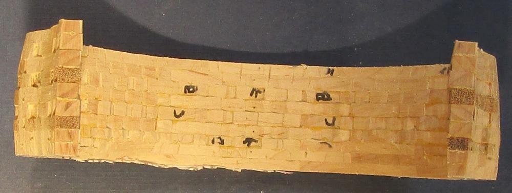
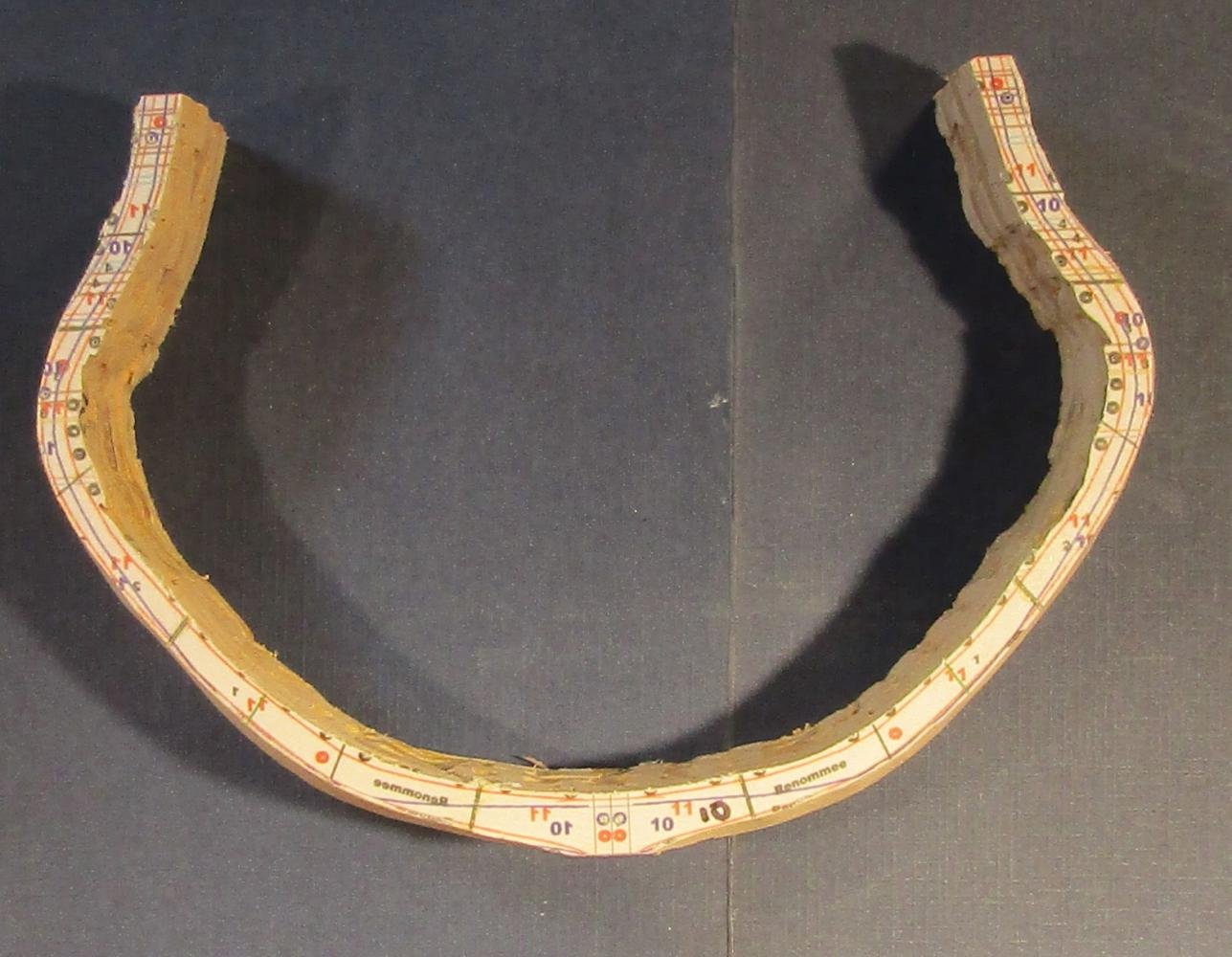
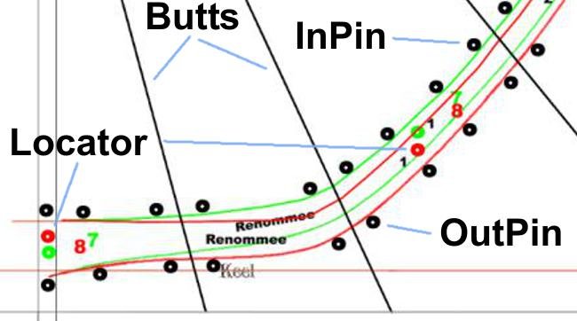
The InPin and OutPin are for #70 gauge holes drilled using bench top drill press. Precisely vertical holes are needed for the 1 3/4" quilters pins (#73 gauge) to exactly align the timbers, first for them the be assembled into a bend and then the bends assembled into a Station Sandwich. When assembled, a Station Sandwich has the same pattern at the same place on both faces. Both the inside and outside bevels can be cut during the same session. The Locator is where a #50 hole is drilled in the timber at each face of a sandwich. The function is to precisely mate adjacent sandwiches. In this instance sandwich 8-7 with sandwich 9-8 and sandwich 7-6. Bamboo dowels hold the sections in position. After the timbers are isolated by a scroll cut and cleaned up, the Butts need careful attention at a disk sander for a tight joint, but not too tight. Copied to a new file, the station is then scaled from 1:48 to 1:60. Alignment pin locations* are placed outside and inside the borders of each station. Locator points are inside a frame to get an exact mating to the station on either side. The station number, the frame number and the name of the ship are placed inside. This is all done using the layer function in Painter. The inside pins and outside pins for any single station are never used at the same time. Experience has taught me the importance of having identity information on each timber. While the shape details for a frame change with a change of scale, the distance from frame that the pins need to be placed does not. This information must be added at the final scale. For me, that is 1:60. Examination of the Body Plan shows that beyond a few stations at midship, there are few places where a vertical hole will usefully intersect both frames in a bend inside the wood. There are even fewer places where a station interval thickness of bends will allow it. Placing the sites outside the extreme outer and inner lines of a pair of stations allows precise alignment at a cost of not much more wood and a sure placement for each layer. * I merged an Ariel Black 7 pt. "o" with a 4 pt. "o". The white center is just enough for a #70 bit and the wall thickness places the hole beyond the face of the timbers. Sliding this figure in place is much faster than placing a 4 pt. "o" marker by eye and hoping it is out far enough. When it is time to isolate the timbers, the thicker wall is wide enough that as long as I stay outside the black with the scroll cut, I do not intersect a hole and ruin a pin location. Station VIII (8) has been isolated and prepared. Station 8 needs no InPins. What is several layers of information in Painter has been condensed here. Station VII (7) isolated and prepared. Stations VIII and VII are merged for this Station Sandwich. The OutPin layer for station VII has been omitted. phot The station sandwich is duplicated and flipped to form the full frame. The published plan has 16 stations. I added a station: the AP ( aft perpendicular). Having frames go all the way to the AP allows for an easier framing of the stern. This additional station is not on the monograph plans. I had to measure and loft the AP shape.

-
One rule from biological research labs: You can never have too much bench space.
-
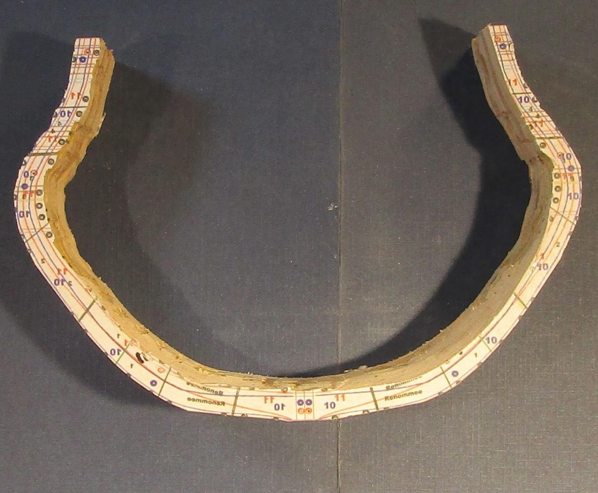
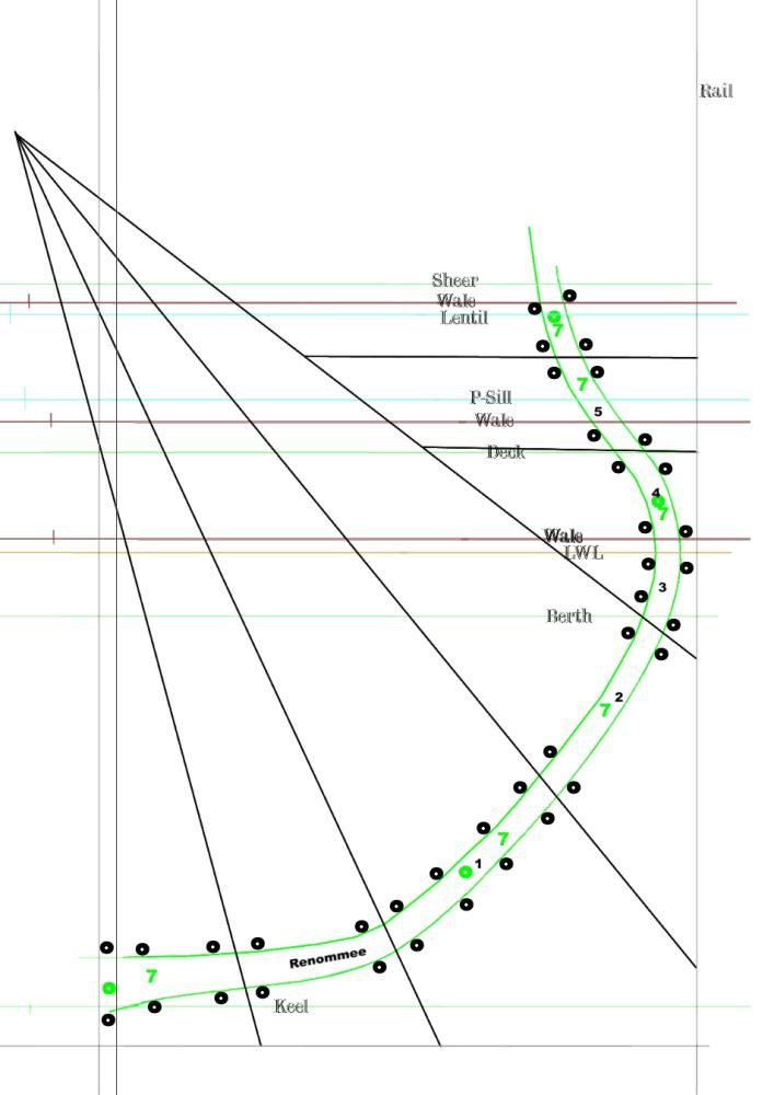
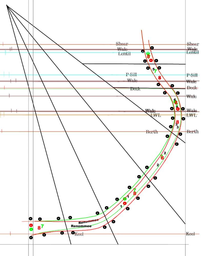
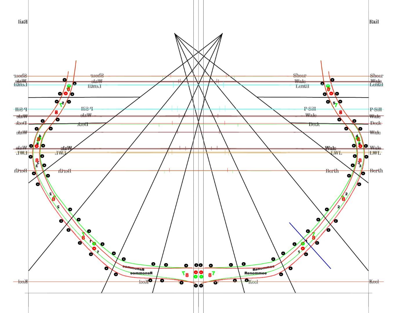
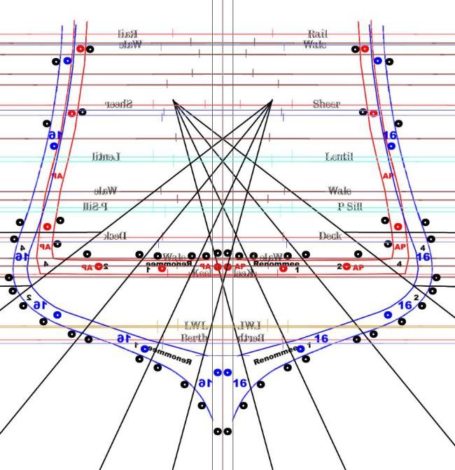
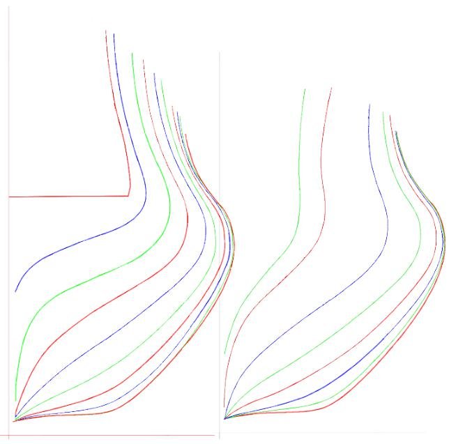
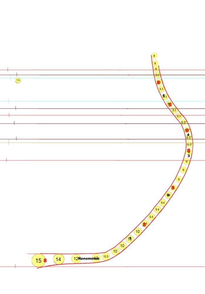
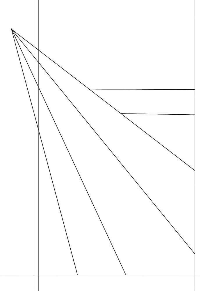
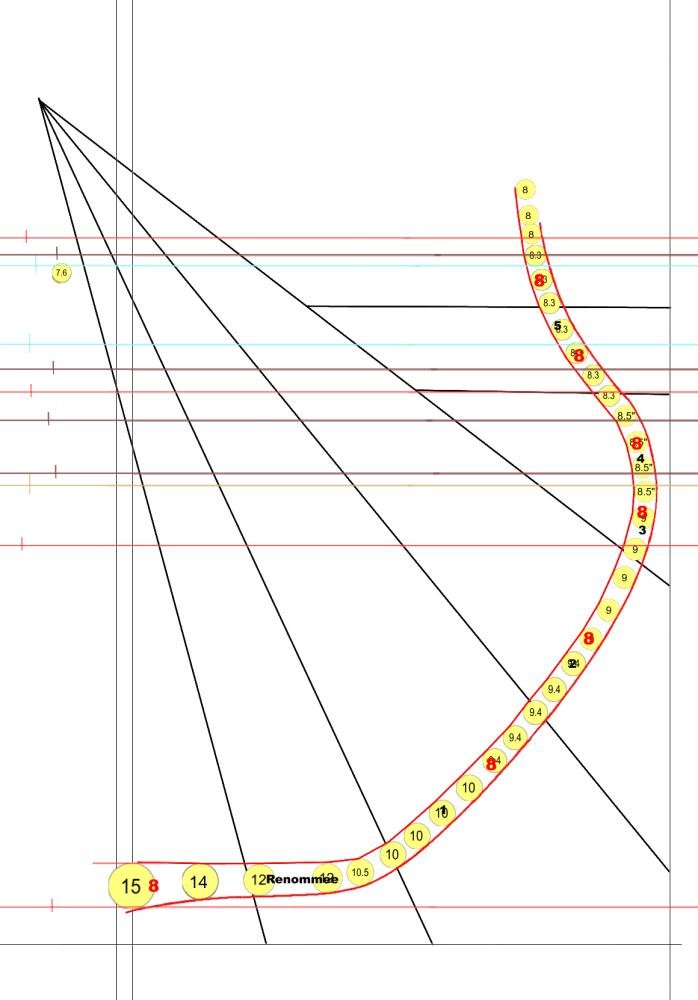
The proper lofting is the first step with my method. The Station Sandwich Method starts with the Body Plan. The shape of each of the 16 stations is individually isolated. The Body Plan is scanned and opened in Painter, my drawing program. A quick view of the shape of the hull is a good start. The ship has a very intriguing shape. The floor is short. The angle of turn of the bilge is almost 45 degrees. There is a prominent bulge at the main wale. The tumble home is marked. The scantlings for the frame timbers seem light in the sided dimension, the molded dimension seems robust enough though. The 15 inch thickness at the keel is equal to that of a first rate ship of the line. I took the thickness data ( moulded dimension ) from the monograph plans. The isolated station lines. They are colored. Each station is isolated on its own layer in Painter. I color each station shape either red, green or blue. I use a rotating sequence It helps me with the orientation of the piece that I am working This is a combination graphic.. This is the mid ship station. After a station has been isolated its moulded shape is drawn*. The location of underside of the rail, the decks, the wales, gunports, the LWL, and top of the keel. The lines for the gunports include a 4" sill and 3" lentil. Each station overlays the same base pattern in black. * The shape for each station is done at 1:48. The majority of available plans are 1:48 scale. My way of drawing the moulded dimension is to use a series of disks, each with a measured scale diameter. Each is placed at a tangent to a station pattern. For La Renommee, the thickness at each point along the frame was taken from the midship frame plan in the monograph. For most ships, the thickness is taken from a Table of Scantlings that is close to the time of launch of the ship. A line is then drawn connecting the tangents on the side of the circle opposite the outer frame shape. This process is quickly done. It is much easier than plotting points and trying to get a line that is perpendicular to the tangent at each data point or drawing arcs using a compass. Doing all preliminary lofting at 1:48 means that these disks only needed to be made once . Using the Smithsonian plans for the clipper Rainbow, I was able to produce a complete set of her frame patterns in 4 days. With determined effort most ships can be lofted in about a week. A three decker is a different matter. But then, a three decker is a different matter in every aspect. The base is the baseline, center line, half of the keel width and butts for each of the timbers. My method for placing the butts is for POF display. These butts describe a diagonal. Each angle is set to intersect the majority of station lines at a perpendicular at its level. Viewed from the side, the butt joints follow an attractive curve from bow to stern. There 9 frames within each station interval that are treated as a unit, which causes the curve to have a slightly stepped pattern, station to station. photo_6 The size of the timbers is that drawn by Jean Boudriot - at least the shape for the mid ship station. Rather than determine the length for each timber separately, I let the diagonal lines do it for me.
-
I use color to keep where I am for shaping easier to keep up with. The dead flat -VIII- is red. The next on either side -VII and IX- is green. Then VI and X are blue. The I start over with red. The red dots above are used for bamboo dowels to mate sandwich VIII-VII to sandwich IX-VIII. So yes, they are locators. The black dots are for the alignment pins for the timbers within a sandwich. The bevel makes trying to do this inside the timbers impossible. I decided to use the model of protein synthesis and add more material to get the alignment I need and then remove the excess when the glue has set.
-
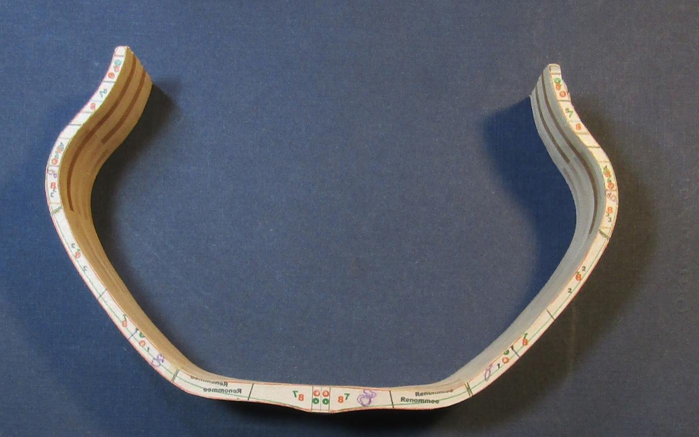
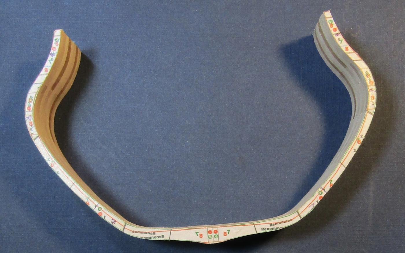
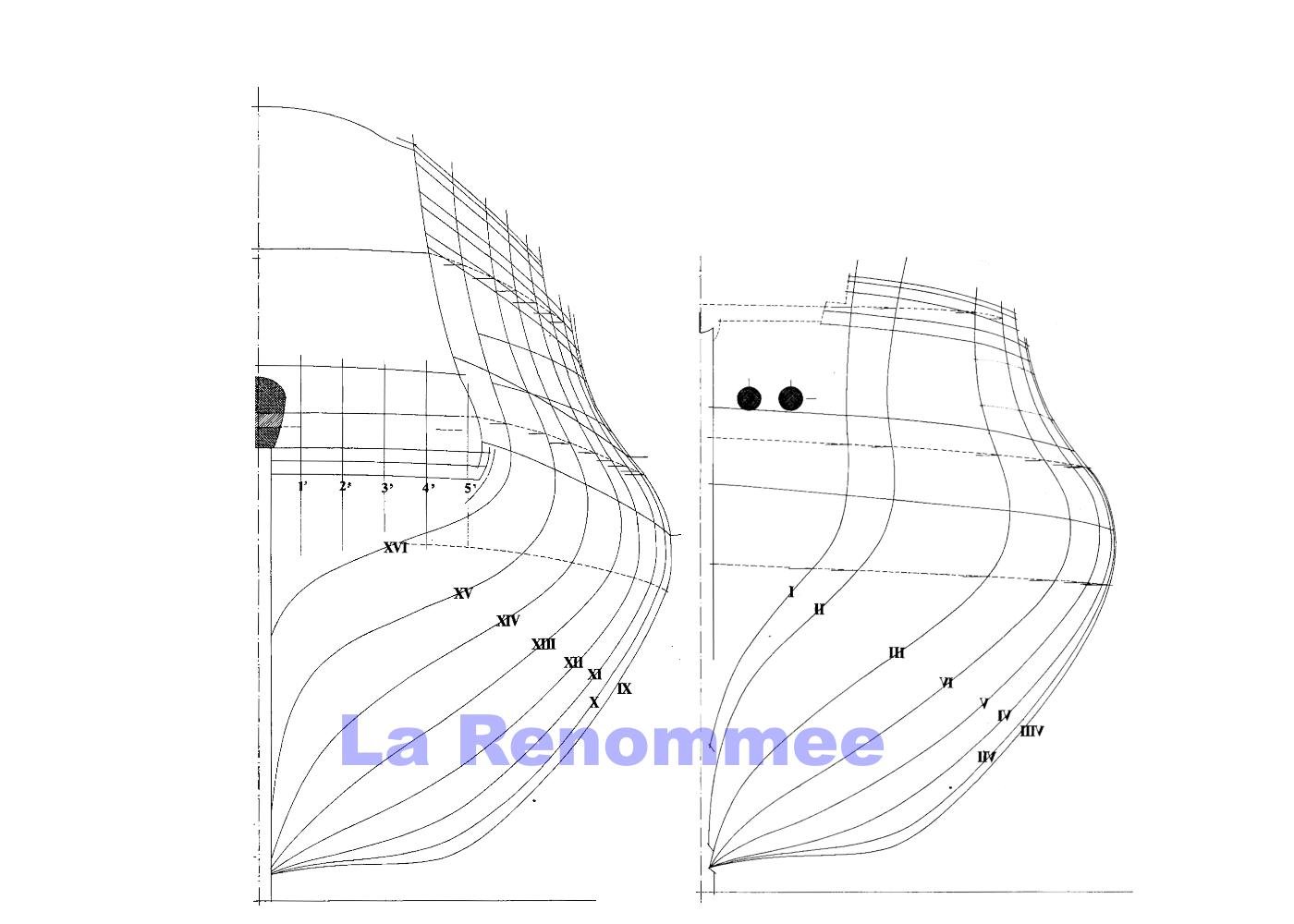
La Renommee - 30 guns - 26 x 8 lb on the main deck - 4 x 4 lb on the quarter deck. 125.75' x 33.75' x 17' Imperial The plans are those of the ANCRE monograph by Jean Boudriot 1993. The monograph includes the lofted shape of each of the 58 bends. This part of the monograph is not needed for my purposes. I will not be using these individual frame plans. I am using a new method. All of the frames between each station are worked as a single unit. For this hull, I have chosen to build it as a solid wall of framing timbers. I usually frame true POF, with spaces. The spaces are temporarily filled for the shaping and fairing of the frames. The space filling wood is bonded using an easily reversible agent. The unit handles as thought it was a single piece of wood and is not at all fragile. The edges of the frames are protected from being rounded. For La Renommee I will PVA bond all of the frame timbers. The lofting required has some similarities with POB level of lofting, but more work is required. In all, the time required to develop a set of frame timber patterns for La Renommee was about 5 days. This is a much shorter time than it takes to loft each frame by plotting it using a drawing board or CAD. My shortest lofting time was 4 days - for the early clipper Rainbow. In general it takes about 10 days. A multi deck warship takes longer. My reading and experience points to this method as being analogous to the way actual ships were framed prior to 1860. The product of the mold loft was likely just molds for the midline shape of the bends at the station positions. Ribbands and experience of the ship wrights would have been used to shape the timbers between. Chocks would be used where I place filling wood. These would not have been removed later. Because the wood for the model is 60 times lighter and 60 times smaller, I can shape all of these frames as a unit. It also allows the wood to be taken to the cutting edge and easily manipulated, as the opposite was necessary for the ship. A Glossary for the terms that I will use: This whole group is a Bend. It is two Frames. Each of the parts is a Timber.

-
Where I have my drill press ( a jewelers size )- there is just wood flour on the floor. The bigger stuff is in the garage. I do keep track of all of the quilters pins, so that I do not find them with my feet.
-
I use a foot switch with my drill press. Harbor Freight has two types: Momentary - apply pressure = ON - raise foot = OFF Maintained - apply pressure = ON - raise foot = stays ON - apply pressure = OFF...... Click - ON / click - OFF Plug either into the house wiring. Plug the machine into it. Fix the switch to a board that is long enough for your heel to rest on. I use the momentary switch. I am bare foot in Summer and sock foot in Winter and just pressure from my big toe is enough. For the type tools that we use, a separate inline dial control to vary the power is better than using a variable pressure foot switch. The cramping from the abnormal foot action would be adverse enough.
-
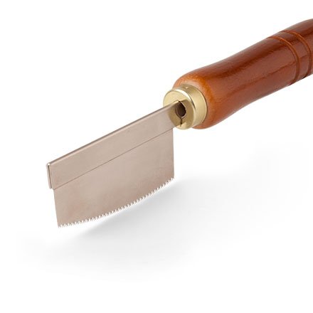
My latest acquisition in Japanese mini saws is this one from StewMac: Japanese Curved-edge Mini Saw Item # 3612 I am able to do fairly close cross cuts with it with less effort than straight edged saws.
-
How to maintenance Byrnes table saw
Jaager replied to michael101's topic in Modeling tools and Workshop Equipment
I was not aware of the oil application. So, no, I am not doing this. I will, when I get to the stage where I need to use the table saw. POF framing does not involve any jobs that require the product of a table saw. At least the way I do it does not. That is where I am at present. If the ship that I am presently framing needed deadwood, I would need it for that. -
How to maintenance Byrnes table saw
Jaager replied to michael101's topic in Modeling tools and Workshop Equipment
3 in 1 type oil or go to a pharmacy and get a bottle of Mineral Oil lubricant. -
Have you looked at the ANCRE monograph for Le Cerf 1779? It is also a cutter and clinker. The different construction for it is that the frames notched. The upper edges of the planks are thicker - the lands are mostly cut into the frames. Buenas suerte and buena fortuna on the clinker planking. I think it is significantly more difficult to do well than carvel.
-
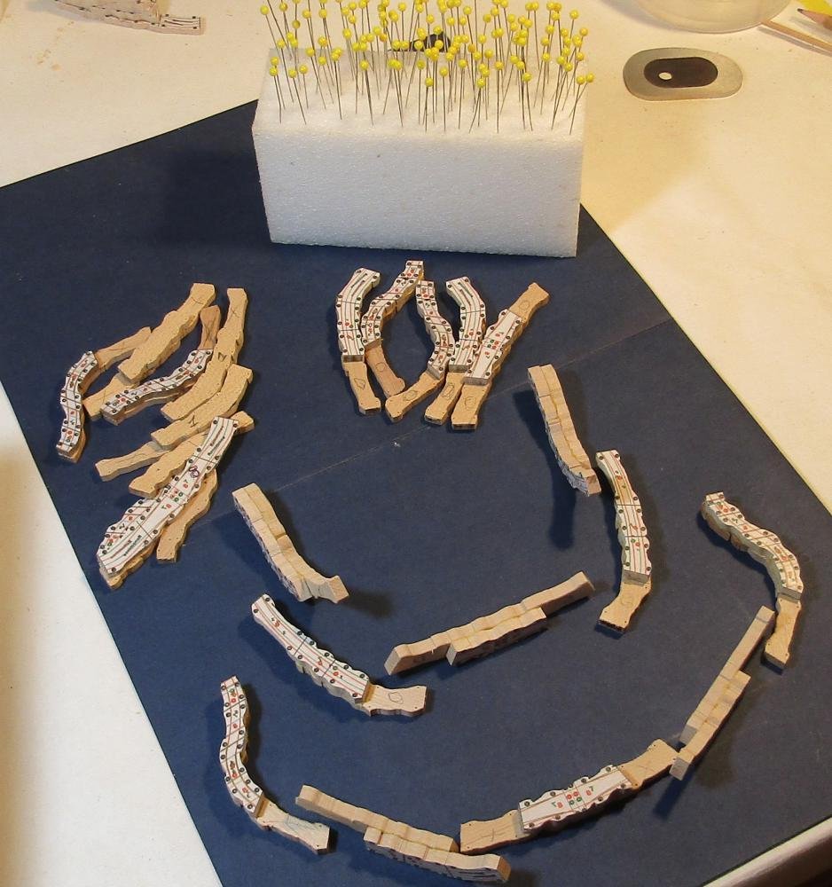
For you workbench and ready access: A block of Styrofoam 2 inches thick - The length and depth your choice - glued to a base of 1/2" plywood. Liquid Nails or maybe PVA to glue it - I know hot glue does not work and organic solvent based adhesives may melt it. My local Home Depot has 1' x 2' x 1" or 2' x 2' x 1" craft and project sized pieces, so you do not need a 4' x 8' sheet. Make holes or slits = ready access, will not dull edges I have more than one.