Jaager
-
Posts
3,084 -
Joined
-
Last visited
Content Type
Profiles
Forums
Gallery
Events
Everything posted by Jaager
-

an easy-to-set high-precision table saw fence.
Jaager replied to Bob Blarney's topic in Modeling tools and Workshop Equipment
Bob, The super peachy keen aspect of the video loop was the digital readout. If only there was a way to get that for the Byrnes saw.... the physical scratches on the micrometer defeat my eyes. -
I looked into Madrone as a framing wood. I am on the wrong side of the continent for the cost to be reasonable - the shipping cost is absurd. I found a source that has solved the drying problem and uses kiln settings that produces usable timber: Sustainable Northwest Wood If I lived near Portland OR I would pay them a visit and pick over their stock for the color and grain. They have 4x4 and 8x4 by 8' on hand. They sell it for flooring and furniture use. The Wood Database information for Madrone reads like it would be excellent for hull fabrication.
-
Worst comes to worst, Historic Ship Models, Mondfeld has a fine print page and a half of Italian to English (Spanish, French, German) at the back. This should cover most all the parts and the book is nice to have.
- 1 reply
-
- 2
-

-
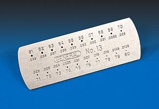
To stir this pot a bit more and endanger the tongues poking in cheeks a bit more: Ductile (can be drawn into wires) , one of the characteristics of a metal, = something I had to memorize for some early science class and got stuck in my head ever since. A jewelers draw plate is a way to do it. I am imagining that a commercial mill heats the metal a bit when doing this. Doing it cold is a whole lot of work, Theoretically, one could start with a thick wire and draw any gauge that is needed. Cooper and brass kinda offer resistance to this, making it not so much fun. Jim's plate is not designed to draw metal. I have Jim's plate and a couple of jewelers plates. The tools that I use most often are a couple of drill gauges: I can sharpen the cutting edge by rubbing the side opposite the lettering on a whetstone. A significant factor is the species of bamboo that the skewer people use. Some of it is really hard, some is soft, and some like to split under stress.

-
Newman Tools Inc has an office in Ottawa. They used to be an interface for Thurston. Thurston is no more. Madco is an alternative. Perhaps, THE alternative in this hemisphere. Perhaps communicating with Newman would provide you with information about what resources are available.
-
I have no recommendations for your choice of kit. From the ones that you have chosen to collect, none appear to be all that difficult. No liners or large frigates, so you are not trying to learn on a subject that would tax anyone, experience or not. I commend you for that bit of wisdom. Were you venturing into scratch, first, for milling, irrespective of dust collection equipment, you would want to do it in an out building. The same for shaping with a belt or drum sander, they throw too much dust for a living area. Ideal, for me for the big guns, a hole on the wall with a clothes dryer or cooking hood outside fixture - but more insulation. Attach that to a hose venting a Rigid 14 gal. shop vac in a sound baffle box ( it is not all that loud, compared to older model shop vacs, but being able to hear music while it is on is nice ). a quality RIF remote ON/OFF switch. Intermediate - something like a Dust Deputy cyclone trap - easier to dump and saves having to clear the vac filter so often. For in the house, a smaller size portable canister vacuum - the kind that is easier to clean stairs with - bagless is good. For a spray booth, I do not see why a large corrugated cardboard box - you can strengthen it by PVA gluing more layers of cardboard onto it A furnace filter at the back and a hose connection for the canister vac hose. LED strips are light weight and generate relatively little heat = inside the box.
-
For temporary and down and dirty way to avoid having to go thru the cleaning process in the future: Make a wire frame - using wire that is at least as thick as what the old style wire clothes hangers were made from. Cover it with clear plastic - 4 mil or 6 mil vapor barrier would be ideal, but clear plastic food wrap would work. When you wish to show the model off, just remove the cage. It may be ugly, but it seems to me that most anything is better than having to do the conservator cleaning thing.
-
One rule from biological research labs: You can never have too much bench space.
-
Where I have my drill press ( a jewelers size )- there is just wood flour on the floor. The bigger stuff is in the garage. I do keep track of all of the quilters pins, so that I do not find them with my feet.
-
I use a foot switch with my drill press. Harbor Freight has two types: Momentary - apply pressure = ON - raise foot = OFF Maintained - apply pressure = ON - raise foot = stays ON - apply pressure = OFF...... Click - ON / click - OFF Plug either into the house wiring. Plug the machine into it. Fix the switch to a board that is long enough for your heel to rest on. I use the momentary switch. I am bare foot in Summer and sock foot in Winter and just pressure from my big toe is enough. For the type tools that we use, a separate inline dial control to vary the power is better than using a variable pressure foot switch. The cramping from the abnormal foot action would be adverse enough.
-
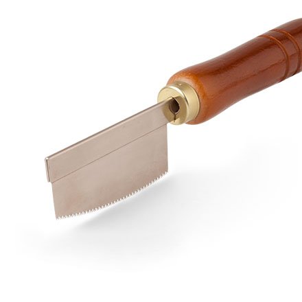
My latest acquisition in Japanese mini saws is this one from StewMac: Japanese Curved-edge Mini Saw Item # 3612 I am able to do fairly close cross cuts with it with less effort than straight edged saws.
-
How to maintenance Byrnes table saw
Jaager replied to michael101's topic in Modeling tools and Workshop Equipment
I was not aware of the oil application. So, no, I am not doing this. I will, when I get to the stage where I need to use the table saw. POF framing does not involve any jobs that require the product of a table saw. At least the way I do it does not. That is where I am at present. If the ship that I am presently framing needed deadwood, I would need it for that. -
How to maintenance Byrnes table saw
Jaager replied to michael101's topic in Modeling tools and Workshop Equipment
3 in 1 type oil or go to a pharmacy and get a bottle of Mineral Oil lubricant. -
Have you looked at the ANCRE monograph for Le Cerf 1779? It is also a cutter and clinker. The different construction for it is that the frames notched. The upper edges of the planks are thicker - the lands are mostly cut into the frames. Buenas suerte and buena fortuna on the clinker planking. I think it is significantly more difficult to do well than carvel.
-
For you workbench and ready access: A block of Styrofoam 2 inches thick - The length and depth your choice - glued to a base of 1/2" plywood. Liquid Nails or maybe PVA to glue it - I know hot glue does not work and organic solvent based adhesives may melt it. My local Home Depot has 1' x 2' x 1" or 2' x 2' x 1" craft and project sized pieces, so you do not need a 4' x 8' sheet. Make holes or slits = ready access, will not dull edges I have more than one.
-
Take the lamp off and use cable ties to fix the hose to the outer arm. A crevice tool at the end. gets it close to the action and it stays in place.

-
Keith, I agree. I did not notice what was checked for the $20 bit. $70 is a different category. Still, for someone who does not intend to turn metal to make tools, but still thinks that a lathe is important to have for wood model parts and does not have money to burn, this may scratch that itch enough to save them from spending big bucks on a precision lathe and finding out that it is little more than a paper weight.
-
River, this could be a worth while heads up. For $20, it is hard to go bad, even if it does not work out. Almost seems like the link should be to Harbor Freight. There is not all that much on a model that requires a lathe. This may do for windlass drums, capstan spindles. The following would probably not work out: Cannons would need to be wood, and belaying pins made of wood. ( Boy, wouldn't doing that about a hundred times be a load of fun?) There is no tool holder or micro adjustment. Rigging a duplicator looks impractical if wood is the choice. The sharp tools vs motor power is a clue that this is right at the edge of useful. I am betting that brass is right out.
-
As an indicator of the characteristics the term Cedar is all but useless. It includes several genus groups and may be more than one family. Being an aromatic conifer may be all it takes.
-
For at least one response - I have no actual experience with this species of wood. From the lack of reply, I guess that few have any experience either. The information that I read in the Wood Database points to it being a poor choice for any part of an actual ship model. It may make an interesting base. It may work for making jigs and other support components.
-
Chocks for futtocks
Jaager replied to allanyed's topic in Building, Framing, Planking and plating a ships hull and deck
Allan, I have a bias and a reason for the omission , but unless this is for a cross section model, what is the reason for modeling butt chocks? With a full hull model, their presence would be all but invisible. In any case, they seem to be a critter pretty much limited to British construction. The same with singleton filler frames, also being almost exclusively British. I understand why they did it. They had more skilled labor than they had wood of the desired dimensions and an all but bottomless demand for the wood. -
Can i live without a BYRNES TABLE SAW
Jaager replied to shihawk's topic in Modeling tools and Workshop Equipment
I use the big saws and a thickness sander to get to one final dimension. The Byrnes saw to get the other. For example, deck planks - band saw / sander a plank to the width. The Byrnes saw to slice off the thickness = individual deck planks. For hull planking - band saw to thickness and Byrnes saw to a width that just allows spilling. Similar methods for beams, deck furniture. It will do more of the job. It can do this. It is just not the most efficient way. Framing = thickness sander - precision is more important than accuracy for frame timbers. I scroll cut my timbers from 2" wide stock. I use a 9" bench top band saw - 1/8" blade with a Carter Stabilizer in place of a scroll saw. I do not use the small band saw for anything else. My 10" table saw is essentially just a table. Getting where you want to go is an individual thing. It is nigh on to impossible to avoid buying tools that will wind up gathering dust, because they do not fit your methods. No shortcuts for this learning curve, I fear. A Byrnes table saw is a high quality tool. If it turns out to be a dud for you, it will re-sell easily - provided you have taken care of it. Shame that you are far away - especially if you have surplus Apple. Too bad about losing to Tenn. But at any rate, go Cats! -
Can i live without a BYRNES TABLE SAW
Jaager replied to shihawk's topic in Modeling tools and Workshop Equipment
Starting from the basics, were I starting from scratch - You are acting as a sawyer as well as a mill. First is attention to harvesting and seasoning. Seal all cut ends - even branches as soon as possible. Debarking and cutting into billets speeds seasoning helps get you ahead of fungus and wood boring insects. Always sticker for air circulation. Getting a log into billets and billets into planks - framing and planking thickness planks - is best done using a band saw. A for real band saw- 14". Do not cut corners on HP - that is false economy. I have a 3 HP 220V Rikon and would not want a less powerful motor. ReSawing eats band saw blades. Steel blades do not last long enough to pay back their cost. A carbide resaw blade lasts a whole lot longer. Long enough to be economical even at the $200 each cost. But there is a more cost effective alternative - a Lenox Diemaster 2 bimetal blade. They are $50 but last at least half as long as a carbide blade if not longer. With the species that you are cutting, the resharpening option is likely an illusion - the steel will crack from the work. No other band saw blade types are even candidates for resharpening. Limited budget or not, this tool is fundamental for what you want to do. Next is precise dimensioning. A Byrnes thickness sander is enough better than the other choices that there really is no choice. Now, this is the stage for the Byrnes table saw. There is nothing else close in quality. The trick is to match the blade to the job. Unless you are doing a particular sort of work that needs it, the tilting table option is not going to pay back its cost. The sliding table is a Formula One sports car. If you budget is limited, it is easy to make your own from lost cost materials. I forget who posted the picture of his version - but he sized the table to allow keeping the fence in place when using it. If you are cross cutting long stock - make two versions of the sliding table. To be practical, the Byrnes saw may in theory cut close to 1 inch stock and it may do for AYC, Basswood, or Yellow Poplar, for the species you have, you do not want to cut much thicker than 1/4" stock. Let the band saw to the heavy work. For what it is good at, there is none better than the Byrnes saw, just to not ask it to do jobs it was not designed for. A 10" table saw can sorta maybe get you billets from logs. It is not the job it is best at. It does not treat blades like they are Kleenex - that is true. But the waste to kerf is awful. The depth of cut is limited - several passes are necessary for 3 or 4 inch deep cuts. Each pass means more work for the thickness sander. It wants to eat your fingers. If any tool is a true luxury for the job of milling stock - it is a full size table saw. -
USS Boston spar dimensions and sails
Jaager replied to Sailinganthony1812's topic in Masting, rigging and sails
Hank, Yup, Norfolk. I am at the edge of Little Creek NAB (or joint something or other). the bark Eagle visits from time to time, Susan Constant was here once. Lots of good restaurants here. You seem to have missed the star over at Newport News: The Mariner's'Museum. A seminar over in the framing forum might be interesting. You are not too far from Hickory - once upon a time a center for quality furniture mfg. I would guess there are nearby hardwood mills. Not Boxwood, Pear or Holly - but a good price on Maple and Black Cherry and maybe Honey Locust? -
USS Boston spar dimensions and sails
Jaager replied to Sailinganthony1812's topic in Masting, rigging and sails
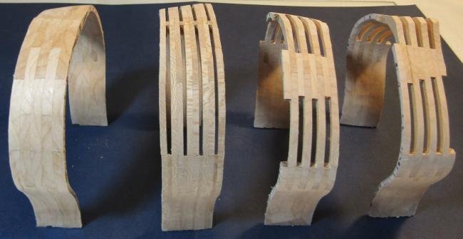
After some thought, rather than going Hahn style with every other bend omitted, the spaces are a bit wide, something new may be worth a try. I am thinking that Naval timber framing style look attractive for this ship. From a distance, it would look like Navy Board framing. I think actual Navy Board framing is not appropriate for ships built after the 1719 Establishments were issued. Never mind that it is very wasteful of timber stock. The three main timbers are just too long and too curved not to be inefficient in the utilization of wood. The old boys apparently cut their frames from solid sheets. Nice that they could get Boxwood and Pear in those dimensions. The first on the right is solid, 2nd is 19th C. 2/3 room 1/3 space, 3rd is Naval timber framing . 4th is Navy Board.