
DONATION DRIVE - SUPPORT MSW - DO YOUR PART TO KEEP THIS GREAT FORUM GOING!
×


Jaager
-
Posts
3,084 -
Joined
-
Last visited
Content Type
Profiles
Forums
Gallery
Events
Everything posted by Jaager
-

USS Boston spar dimensions and sails
Jaager replied to Sailinganthony1812's topic in Masting, rigging and sails
The SI was impressed with Boston to use the lines on the cover of their warship plans catalog. Elegant lines. I bought the plans and worked the up for framing. R&S is 24.25" Using the scantling in Steele - the sided thickness of the frames leaves very little actual space - mostly enough for air circulation. As built, leaving off any planking to show the frames would display a solid wall of timber - with narrow gaps. This ship would work for frame display if every other bend was omitted and the frames were 12.125". Doing this saves on wood, too! I would use Steele as primary, and AOTS Conny and AOTS Essex to supplement. If there is no ship specific data and you make an informed guess, who has the bones to denigrate your choices? I would not let the lack of contract data stop me from building Boston. That there are many more ahead her in my queue, has her a low priority in my shipyard. -
You might give some consideration to giving the "bolt heads" a pass. They were more like nails and are not seen from a distance that is not that far away. They are not proud, rather flush or a slight dent. Most of the hulls with bumps remind me of an old picture of a severe case of smallpox in someone with an incompetent immune system. Individual plates from a copper sheet? On a piece of safety glass - score with a very sharp #11 blade moving along a steel straight edge. Snap along the score. Attaching the copper can be a problem. Old Model Shipways technique called for using a candle to darken the copper and then using Weldwood contact cement. They did not say to scrub the glue side after flaming it. What happened is a layer of oxide on the surface that cases the cement bond to fail. Treating the copper sheet to a color change before scoring may either leave the other side unaffected or allow for easier process of cleaning it. I am a long way from actually doing this experiment, but I have it in mind to use archival paper with a smooth surface. Paint one side with Modern Masters ME205-06 Metallic Antique Copper, before I cut plates, wondering about a Guillotine Trimmer for the cutting, attach with bookbinders PVA, and use Modern Masters PA901-04 Aging Solution Green Patina in various places.
-
The distance from the top of the deck to the top of the port sill was a defined distance. There was a formula - the caliber of the gun was the determining factor. The slope of the sill followed the slope of the deck under it. It was not horizontal at the ends of the ship. Rather than a rectangle a gunport was often a parallelogram with vertical sides.
-
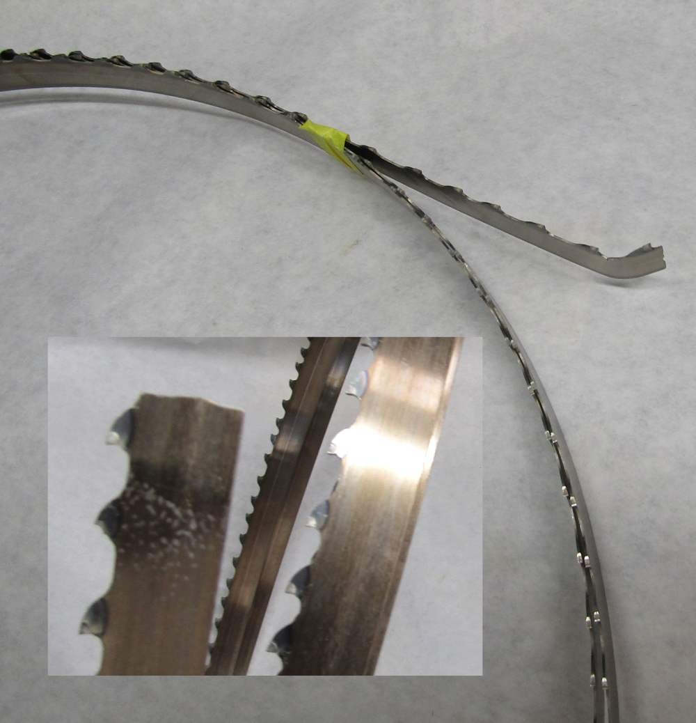
Your sheets look wider than 2.5" . So you set the 10x4 face on the table? You know what your grain pattern will be doing that. I use 8x4 and the 2" face is against the fence. I do get an interesting variety of grain patterns with Hard Maple this way. I have a 3HP Rikon and my Resaw King broke. The tension is serious, so the bang was LOUD. I paid a tech from Wood Craft to set my saw up and he set the tension. It reads dead on for 1/2" on the gauge. Bent the blade so no rewelding. It was under warranty so Laguna replaced it. They required this picture. It was way back in the queue, but it got here. The finish and thin kerf with Wood Slicer is really nice. It just does not stand up to Maple for enough linear feet of cutting to pay its way with me.. I went thru the whole wider blade - less wander thing. I used an Emco BS3 3 wheel benchtop band saw for years. As the blade dulled, the wander became a problem. I have had no wander with the Rikon with a 1/2" blade. The internet video that advocated setting the teeth at the crown of the top wheel pretty much avoids wander for me. The Lenox Diemaster 2 bimetal blade seems to be an effective alternative to a carbide blade. It is about twice the cost of a Wood Slicer but may last 80-90% of the life of a carbide and about 10 times longer than a Wood Slicer. I do not work for Lenox, so I have no investment here. I am just offering what I think is an economical alternative. Given the propensity for any steel blade to break on me, I am thinking that the carbide resharpen option is more of a mirage. It softens the resistance to the $175 outlay.
-
Chuck, At $150 per blade, you seem to be buying a carbide tipped blade. I am guessing ReSawKing. The main alternative that I have found at Highland is about $25 more. I have a local shop that will weld a blade while I wait. The owner repaired a 10" carbide Freud tablesaw with a broken tooth -back to like new. Anyway, he put me onto Lenox Diemaster 2 bimetal blades. I use the 1/2", 3tpi, 0.035" and my saw is 142" so each is $ 57 . I checked Bandsaw Direct and they are $55. For my size a Wood Slicer is $44 and it dulls and a bimetal lasts maybe 10 times longer. The carbide will last longer than bimetal but nothing like 3 times longer. It is to cry when a carbide blade snaps. When I cost it out, I think the bimetal is a lot more cost effective. It will only cost you about $50 to do the test on your saw and see if the economy is there for you.
-
Wow, Bruce !! Boxwood! logs though - likely not too large- Unless it is possible to access a band saw 14" or large - processing it will involve frustration and agony - would not consider it for framing but grabbing a serious supply for use as blocks, catheads, davits, bitts , belfreys, is worth considering. The Pear though - if it is quality and is 4x4 or 8x4 and the price is reasonable - back up a truck and fill it. Matrim, I would score everything on your list as an excellent choice but the Red Cedar. I have no experience with it. Beech seems similar to Hard Maple but a tad darker. Hard Maple and Black Cherry are my choices for framing. They are domestic species for me and easy to get. Basswood is way too soft and iffy about holding a sharp edge to me. Lime is the same genus but a bit harder - enough harder, I seriously question. Yellow Poplar is similar in hardness, but it works as though it were a lot harder. It will hold a sharp edge. The stock that I have gotten is excellent for framing - if you totally plank over it. The color range in a single board can go from tan to green to a color that looks like creosote treated Pine - ugly brown. Good looks ain't its thing. POF uses a lot of wood. A frigate @ 1:48 - you are looking at maybe 10-20 BF. More if you cut your frames from stock that is glued into a "U" and cement the frame pattern to it, a lot more. The volume of wood used for everything but framing is reasonable enough to make using imported species worth considering. For framing, it makes for a more reasonable budget outlay the use species that are domestic where you live. While good Apple is king, it is a bear to obtain. Your Pear - Pyrus communis - steamed (Swiss) or not comes in a close second. I love Black Cherry, but Pear is better. The hard species of Maple domestic for you is Sycamore maple, European sycamore Acer pseudoplatanus. It is probably close enough in hardness to make not worth paying a premium for imported Acer saccharum. Because Underhill praised Sycamore Naple, but called it Sycamore, I bought a supply of our Sycamore - American Plane Platanus occidentalis . A more awful species would take work to find. well maybe Siberian Elm or Lombardy Poplar.
-
Starting to restore pond yacht.
Jaager replied to walter.hobbs's topic in Masting, rigging and sails
If spars are missing, or too damaged to repair, fix that. Do it in a way that matches. I totally agree with Bob, refinishing is not the wise choice. If this model was ever intended to sail in an actual pond, it is not probable that shellac was used as a clear finish final coat anywhere on it. Shellac loves water. It loves it so much that it grabs it and turns white. In the 1930's a water proof clear finish would be vanish. Traditional varnish - boiled linseed oil cooked with shellac in mineral spirits or terp. Carefully remove any dirt and muck condensed on it from the its environment - look up restoration cleaning methods. Give it a home that protects it from dust and temporary gaseous goo like tobacco smoke and frying oils. If something bright and shiny for you to sail is your original goal, I suggest that you leave the old girl in her retirement and build a new one yourself. -
This is not exactly the lay of the land. My view of it is that there are more than 3 types. I do not use 2 of the 3 that you have listed. Contact glue/cement - here Weldwood is the common brand - has zero place on an actual ship model. I use it to fix sanding media (cloth backed) to the Maple drum of my homemade thickness sander - difficult and messy to remove. CA - do not use it - probably a generational thing - but when I did try it, I never got much use from a bottle before it dried up. Depending on brand and conditions, if want a model to last a hundred or more years and not just 20 or so, the long term stability is open to question. PVA - comes four main flavors - white - OK, but I do not favor it, yellow - carpenter's glue I use the water resistant Titebond II brand, brownish - fully water proof = Titebond III (really acidic), archival white - bookbinders neutral pH - safe for rigging lines made from natural fibers ie. linen or cotton. Epoxy - many types - the bond for metal to wood Hide glue - really traditional - not used much - the liquid variety is in disfavor because of its high water content (probably). The glue pot type is messy and time consuming. Fully archival. Before it sets, PVA squeeze out is easy to remove - scrape it or damp paper towel - once set a very sharp edge - it is a plastic. Undoing a bond - near 100% isopropyl alcohol and a heat gun. Are you sure it was not wood that had been dyed? A wood dye penetrates wood and does not affect its pores or surface. A stain is really semi transparent paint and it is pointless and bit mad to use PVA on a painted or stained surface. Wood bending? The tools to do it? You pays your money and you takes your chances, Whatever works for you. The most important factor here is your choice of wood species to try to bend to begin with. A few bend well, most sorta do, and some resist bending to a degree that makes it not worth even trying.
-
Does resistance soldering work for this sort of work?
-
Jim, what is done under the term "kit bashing" here is hardly bashing. It is far more like kit improvement or kit augmentation. What it really is = partially scratch building a kit model. There was a time when this was the primary path towards full on scratch building. It was years ago that I first encountered kit bashing - it was plastic models and it was things like adding P51 wings to the model of a "56 Chevy. In our world it would be mounting a 5 inch gun turret in the waist of Drake's Revenge and replacing the swivels with M2. You might think that it could be further bashed by adding a Volvo Penta and a prop, but that has already been done for real on a replica of a near contemporary of Revenge, the Susan Constant which is over here at Jamestown.
-
If what you have is Lovoa trichilioides - what the Wood Database lists as African Walnut, trying to get a serious bend is fighting against the basic structure of the wood. The grain is likely interlocked. This offers resistance to the fiber bundles sliding along side each other to produce a staggered formation. It might be more productive to substitute with a species that allows bending. Then spend the additional effort find a mixture of wood dyes that color the substitute to match the Walnut that you have used.
-
Not a recommendation, just a comment: My background is in the Biological Sciences, and HMS Beagle has a role similar to an icon. Beagle had been a will-o'-the-wisp as a subject for a model until 1997. Then it became my first choice to build after retirement because Karl Heinz Marquardt authored an Anatomy Of The Ship volume covering HMS Beagle. I scratch build and have been able to loft the framing for this ship, using the information and plans in the book. I even have the necessary stock of framing wood. I have long been diverted from building Beagle. I have decided to use 1:60 as the scale for all of the ships that I model. I have a "rule" against modeling a ship that is available as a kit. Sort of like the on going mission of the Starship Enterprise: "to go where....". This new OcCre kit - at 1:60 - has provided me with a bit of a dilemma. Being POF it would not be mistaken for the kit, but still... OK, enough irrelevant rambling! The AOTS volume - while possibly difficult to buy - is probably also the basis of the kit. It also provides information that allows for an extraordinary level of detail - if you so choose. In addition the information and level of detail for the spars, rigging and sails is extensive and is matched by only a few other vessels. If the rigging gives you pause, the kit plus the book provides enough information that an y impediment will be at the level of your effort and not due to a lack of information.
-
Unless the case has good ventilation, it could turn into an oven. I think the effect is = visible light passes thru the glass, upon striking a surface inside it loses energy. The lower energy is IR and it reflects from the glass and bounces around inside or increases the temp of any material that it hits. Man made fibers are catalyzed cross linked polymers. UV can act as a catalyst to produce additional cross linking. The more cross linking, the more rigid it becomes. Rigid is brittle, until under any stress, even a change in temp, it shatters. The location that you have chosen increases the rate at which organic materials follow Nature's imperative to return to CO2 and H2O.
-
Afonso, My suggestion was that you build completely from just plans and materials that you directly obtain. I based this on you being on a mission and seriously focused on it. I see now that you are coming in to this with less of a view of this landscape than I thought. Before the internet, when starting this, it was a local club - if you were extremely lucky, otherwise it was books and magazines or journals dedicated to ship modeling and books about building the original ships, some of the books were reprints of books written at the time of the ships. The best of the books and best of the journal articles demonstrated and encouraged building from scratch. Unless your previous experience involved woodworking at the cabinet maker or fine furniture maker level, the learning curve was/is steep. It pretty much requires owning or having access to some fairly expensive tools, especially at the milling your own stock from lumber stage. When you have the materials - mainly wood stock with the proper dimensions - expensive tools are not necessary, but they make things go faster and easier. But you still will not be able to mimic Graham Chapman and build a model in bed, at night in the dark. (Monty Python) A ship, especially a warship, involved/involves the most advanced technology of the culture building it. It is a serious endeavor. Should you wish to build a model of one, a model that is reasonably close to the original and that, in your imagination, could grace a museum, building it from scratch is still the way. This is especially true if your subject is unique or has been rarely modeled. Kits are primarily about making money for the mfg. They require being economical with the component materials, using methods that as many as possible can execute, and subjects with broad appeal and are supplied in large numbers. At the extreme, it is about selling a fantasy, an expensive fantasy that is more often than not beyond the existing skills of the buyer. At that level, the skill involved in the overall process is in the advertising, not in craftsmanship.
-
You could maybe buy some wider stock that is the thickness of the planking so that it can be spilled. Before you segment the planking area, two planks need to be in place and correct: The lower wale and the garboard. For the garboard, only one edge should be spilled and that is the edge that meets the keel. Mark's lower red line is the garboard and his length is how long it is. It does not chase the rabbet up the stem. In the era of your model, I don't think the ends of the wale strakes tapered at the ends. Get some thick hard pressed cardboard and fully plank with it. When you get that correct, the pieces can be used as patterns for the wood. But the more wood strakes are applied, the less reliable will be the cardboard patterns. But new ones that fit the smaller space would be better.
-
Afonso, First off - what is your location on Terra? Second - You have set up a situation with mutually exclusive requirements. Kit + 16th C.,17th C., + Iberia + accurate There are a few vessels from that time with documentation. Vasa is sort of at the top - Northern Europe . Most of the recent finds from your area of interest have been done by nautical archaeologists. It is my impression that they do not hold us in high regard. Little that they find seems to reach us in a form that we can use. Should you change one requirement = kit to scratch, there are several possibilities. This requires that your standards for accurate be realistic. I have series of books about an Iberian find at Red Bay, Canada, these plus the recent articles in SIS documenting a model, could be the basis for a build. The following will require loose, very loose limits for accuracy: I have plans for a Manila Galleon - also SIS I think. This part of SIS is now NRG content? AOTS has a volume with speculative plans for the first squadron of C.Columbus. ( also from Britain Mary Rose and Susan Constant ) Wm Baker did plans for Mayflower - with some aspects and choices being seriously questioned. In the 1970's there was available from Verlag Delius, Klasing & Co. a series of books with plans for your time of interest. They may appear for sale from time to time. Osprey has a Spanish Galleon issue. NIP volume - probably Conway - The Galleon by Peter Kirsch. There are several books about Kogg finds. The maritime museums in Iberia may have plans or plans of reconstructions. Until your skill level reaches a level where you do not need to ask, I seriously advise sailing well away from kits or plans for multi deck warships - especially those from the 17th C.
-
Tailing deck beams
Jaager replied to allanyed's topic in Building, Framing, Planking and plating a ships hull and deck
What may have been going on = The number of trees that are suited for warship construction is finite, especially on an island that is not all that large to begin with. In the zeal the build a large navy, all of the large old growth Oak was cut. They had to sacrifice their standards to match what they could obtain. Unless the project is a cross section, in a model, it is a detail difficult to see. A close, but easier technique; have the clamp stop at the bottom of the beam and fit a short piece of the same wood between the beams that is the depth of the dovetail. Done well, the glue joint may appear to be wood grain. -
DeAgostini Model Space Sovereign of the Seas 1:84
Jaager replied to RickyGene's topic in Wood ship model kits
Rick, This may have been Fate handing you a small mercy, and a choice to take a kinder path. I have a recollection of reading that far more SOS kits may reside at the back of closet selves than ever see completion. Building the original helped trigger a revolution. The ship is a first rate liner. It had more sculptures than a lot of museums. A sail flagship is a formidable challenge no matter how many models in the experience bank of the model shipwright. The salesmen weave a fantastic illusion of what you can have on your fireplace mantle, and try to trigger an impulse buy. It is not dropping a beginning swimmer into the deep end, it is dropping him into a storm tossed ocean with rip currents and whorl pools. Consider a project with a higher probability of completion to begin. Lots of advise here on what may be a good choice. Then, when you are ready, given where you are, maybe scratch build a model of Otway Burns' Snap Dragon. Then, if truly mad, the 74gun USS North Carolina. -
Intrepid (or more likely foolhardy!) newbie
Jaager replied to SottoVoce's topic in New member Introductions
You could start your new log with: "for the steps preceding this point, see this log" and place a link to it. -
Right angle attachment
Jaager replied to Kurt Johnson's topic in Modeling tools and Workshop Equipment
This is switching to a new lens with a broader view: MicroMark is a US agent for a line of DC powered tools from Kaleas Minitool , a German company. In the US marketed as the Micro-Make brand. One of the tools is a MicroLux® Heavy-Duty Right Angle Disk Sander / Drill. The power of the sander is greater than one would expect. There is a 3-jaw chuck for it, for drill bits, I have not tried that function. The tool is a box instead of a rod in shape. Certainly not inexpensive, it requires saving a lot of box tops. It is about the best power tool that I have found for sanding inside a POF hull. If you are drilling inside a hull and the bit size is #60 or smaller, there are a lot of inexpensive DC motors - small to very small and some have 3-jaw chucks - mini chucks. AliExpress - a Chinese agent for a bunch of their mfg - has a lot of choices for motors. I have not needed anything from there since the trade war began - no idea about its effect. Marlin P. Jones is a US supplier of small DC motors and a very useful = selectable output DC bench power supply for under $20 - the range is six levels from 3V to 12V. This is an easy way to control the speed. The motors are small enough that if you can get your hand in, it will work. The small gage of the power wires - they do not get in the way. -
Need CAD type program
Jaager replied to Sambini's topic in CAD and 3D Modelling/Drafting Plans with Software
CAD = computer aided design * (the verb may be a different one) Assumptions: You are starting with an existing plan and lofting hull components from it. The actual design has been done. You wish to replicate parts of that design at you target scale. Lofting In Painter I having been doing a lot of this (frame patterns for over 70 hulls). I use a raster based program. It does not do smooth curves as such. It does line segments. The more segments, the smoother the curve. Theoretically, what I get is a series of facets. I patterns that I print out look smooth enough to begin with and even if it were facets, I can not get anything but a smooth curve on the wood from my sanders. I use Painter 19 - I already had an earlier edition from my time with 3D CG. I could not justify the expense of Painter for just this part of its functions, were I just starting out. GIMP is free, but it is a Photo Shop clone and brings a heavy load of functions with it. Photo Shop will do it, but is not cost effective as a stand alone and a money sink on the Cloud if this is to be a continuing enterprise on your part. Paint Shop Pro is about $50 +/- and provided it can handle the potentially huge number of layers and large file sizes should be enough. Painter 12 could not handle my file size in a single file - it added random green blocks when some threshold was exceeded. Several smaller files solved that = Fore alone - one series, Aft alone another series- lofting at 1:48= one file , reduction to 1:60 in another, cutting the 1:60 frames into timber patterns a separate one or two files. It makes a big difference depending the size of the ship. A 118 gun liner stresses everything - all the way. A pilot schooner is a snack. Irrespective of your choice of raster program, you will only be needing a relatively few functions. SAVE - a function you will wish that you use more often than you do - unless you enjoy plowing the same furrow over and over. COPY, PASTE, CUT, SAVE - big help is having a gaming mouse with programmable buttons for these. I burned out the left click on several expensive brands. I am getting excellent use out of a Redragon M711 Cobra Gaming Mouse @ $20 I can burn thru a lot before I equal what a Logitech cost me and it is lasting longer to begin with. For a brush - a thin line - (Painter buries finding a useful brush within an incredible number of options.) Paint bucket fill tool - having frame lines as different colors helps in seeing what to cut - With two timber faces on a pattern I cycle just 3 colors R G B - in that order. I know if it is R G, red is always the midship face, if it is G B , green is midship, if it is B R , blue is midship. The placement of the floor timber matters. It is easy to get confused at the sander, A system helps idiot proof things. Rectangular Selection tool and Polygon Selection tool cover this function for me - plus any erase needed Magic Wand - good for removing the background from a scan and making a layer transparent except for the lines of interest. SCALE is vital so is Rotate selection I do not use many more functions than these. Not much of a learning curve. To begin, to save what I aim to print, I had select a canvas size that Windows Photo Viewer all not "adjust" for my printer. I use pixels as the dimension units. Home scanners to do not provide a 1:1 copy. I had to determine an adjustment factor for every scan. For MY Brother machine it is 102.5%. The first thing I do to any scan when I import into Painter is to SCALE 102.5%. Before I do anything else - bad results if I miss doing this. Once I found a page size that Windows will leave alone, I scanned a transparent metric ruler and printed copies at ever more precise scale adjustments until I got an exact match. This is tedious but necessary. After importing a scan, adjusting the scale, removing the background, the next fun ting to do is to rotate the scan back to vertical with your base vertical Y line and X baseline. The only concession I have made to CAD is that I saved a long thin vertical line using TurboCAD that I bought from an end cap display. The finest line that Painter will do is 1 pixel wide. I wanted thinner for within the program and a PNG import from TurboCAD provided that. The patterns that I work with can't be any finer than what a point is from my ink jet printer so the precision is limited to Painter. -
Mark, I did not notice until your replacement molds made it obvious, Belle was a bit of an out layer. The degree of hollow at the bow is more than Sea Witch even and Griffiths was heavily criticized for designing that. I wonder why Belle did not set a trend? Dean
-
Jolly, If you have any ambition to go to scratch building, get as much and more of what Haiko is offering as you can even unrealistically handle.. Work a deal and use specie even. This is especially true if what is being offered is 4x4 or 8x4 (or your domestic equivalent of those dimensions). If your living situation is limited, long term rent a small storage unit. Debark, seal all cut ends ( surplus house latex paint will do if gobbed on super thick - a piece of Bounty will do for a brush) - sticker between pieces. Find a storage unit location that is not prone to termite or carpenter ant invasion. Maybe spread Borax fabric softener on the floor - kills roaches - maybe other beasties react against it too - study up. There is also a local species of Buxus there, see if you can get a bunch, a big bunch. If you do come over to the dark side, you will probably always regret it if you miss this. Think Scrooge McDuck in his vault of gold or Smaug in his. Get with your fellow countrymen who share this interest and pool your efforts. Let me add some of my perspective on this. I come at this from POF in the 1:48 to 1:60 range of scales. It is difficult to grasp just how much wood it takes to fully frame a ship at these scales. An impressive amount winds up as saw dust. Tackling a liner will give you a real appreciation for the stress on the treasurer who had to come up with the money to pay for a real one or the sawyer who had to obliterate a forest to supply the wood needed.
- 14 replies
-
- 3
-

-
- south africa
- wood
- (and 1 more)
-
Ab, I am not suggesting that actual frames would slide. Deane constructed about 4 design cross sections, the dimensions of their arcs were determined by various lines drawn on the initial profile - OK, their position determined their shape - so no sliding. It just seems to me that by later "adjusting" their location, interesting effects would be seen in the shape of the hull. I guess as long as the accepted rules were followed for design, a dud would not end a career. Take an off the wall chance on a design and if that is a dud, it would on to sweeping out a stable for a living. I see from the NMM plans that the RN seemed to be obsessed with using the top timbers to frame the sides of the ports. There are some labor intensive jogs drawn on some. I think the Dutch were in the decided majority in placing the ports where they wanted them irrespective of where the top timbers were. The majority seemed to have more wood higher up, so weakness was less of a problem - just add more wood to the other side of the timber. . The RN seems to have been rather spare with framing in the upper works. ---- if you plank everything above the LWL in and out on a model, it does not matter anyway. I make it a solid wall of framing up there. It locks the frames in position and turns a fragile area into a strong one.
-
The sliding part is my conjecture. Whole moulding tends produce hulls with a generally similar conformation. Were I a designer at the time and was interested in producing something faster or more stable, doing the experiment of moving the fore and aft design stations and observing the effect. would only involve erasing lines that were a failure. Granted - the vellum was probably expensive and doing a lot of handling of elemental lead was gradually making the draftsman dumber. I have done a very preliminary lofting of the 7P IV , the big one that followed the famous 7P, compared to English and French contemporaries there is a long section in the middle where the shape does not change. It seems that more than a few 17th C Dutch plans available to us replicate the mid ship bend a bit more than those of other countries. It reminds me of a barge with a long sculpted bow and stern as opposed to the oft duplicated illustration of a fish superimposed on the profile of a race galleon - an attempt at streamlining? Where change is constant. Home waters that are a bit shallow - a deeper wedge shaped hull would sort of not work out too well?