


Jaager
-
Posts
3,084 -
Joined
-
Last visited
Content Type
Profiles
Forums
Gallery
Events
Everything posted by Jaager
-
 I build POF and am a bit biased on terminology. As a side note, what you ( and most everybody) call bulkheads are actually molds. Subs have bulkheads, some steel ships have bulkheads, Chinese wooden ships have bulkheads. Western wooden ships did not have bulkheads. They certainly are not frames. What you (and everyone else) call the keel is actually a central support spine. I have never built POB, so this is theory. How I would try to rectify this: 1. This curve is the natural shape that your piece of plywood seeks. Anything that you do only to it (bend it back with steam or heat) is likely to be a temporary fix. It will still "want" to bend. You can clamp it to a baseboard and use the planking applied while clamped to hold the shape. But when removed an twist force will be on the glue joints of the molds and inside planking - forever. It may or may not hold. 2. If the molds have not been glued, there is a stronger fix. Scab a long streamer on each side of the central spine. Remove the black area on each mold. Get a couple of long sticks of straight hardwood ( 1/4" x 1/4" or 1/4" x 1/2" or substantial size ). Drill holes thru the sticks and central spine all along the length. Use threaded bolts, washers and nuts to fix the sticks and central spine together. Make sure this assembly is dead straight. Remove the assembly. Glue the molds to the central spine. Slide the sticks thru the holes along the length and glue the sticks to the spine. Check to make sure it is still dead straight. The bolts can be removed and bamboo skewers glued thru the holes. You just need a drill bit that is the diameter of the skewers. 3. The holes in the molds remove some of the bonding surface between them and the spine. Short pieces of SQUARE wood can be used to reinforce the bond. Eight pieces per molds. Just do not block the path of the straightener sticks. 4. Rather than Balsa, consider using Pine to fill the outer planking edge between the molds. Assuming that you do not have power tools, a hand fret saw. planes, knives and sanding block will do. Select Pine in 1" thickness is easily found. There may also be thinner stock of solid Pine. Cut out the shapes, glue up the layers to fit between the molds, and do as much shaping as you can before fixing them between the molds. You are unlikely to be lucky enough that a sum one 1" layers will be a tight fit between the molds. The outer surface does not need to be continuous. Cardboard or what ever is to hand can be fitted between a layer to make up the difference. It does not need to reach the outer shaped surface. You just want the unit to be a push fit between the molds.
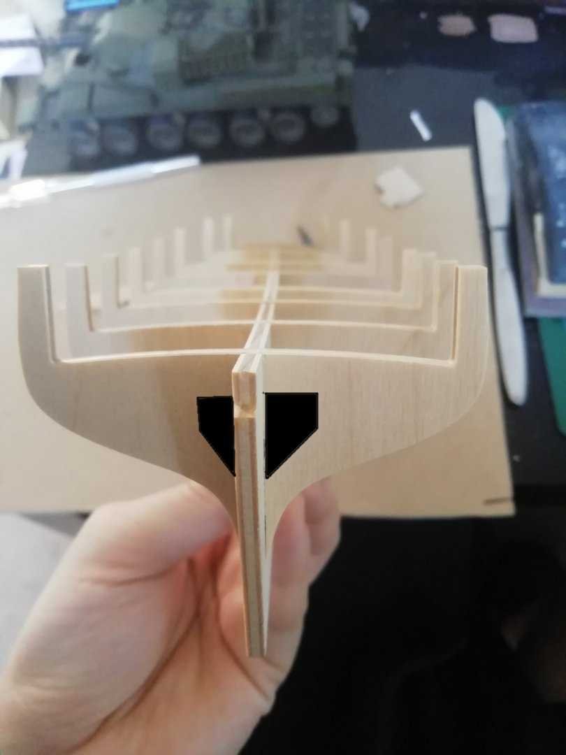
-
Scale bright work
Jaager replied to Kurt Johnson's topic in Painting, finishing and weathering products and techniques
A stain product is actually a semi transparent paint. Cherry stain would be used on something like Yellow Poplar, Using a dye on Cherry is gilding a Lilly. Using a stain is turning a star into something mundane. If you want a finish with a reverse gear, consider shellac. Orange shellac will darken it now without obscuring it. But, as Marks writes, Black Cherry darkens over time and in few years may be darker than you intended. Super blonde will not darken it much. There is a clearer version that is about twice as expensive. The more layers, the more depth. If it is too shiny a light buffing with very very fine steel wool with make it satin. Just do not get it wet. I am of a mind to use a final layer of Renaissance Wax Polish- but that is just a theory now. -
Being unforgivably pedantic, if that model was a kit, there is slight probability that it was POF. Plank On Frame is a specific style of construction that attempts to mimic the way an actual hull was constructed. It varies from stylized to being as exact as possible, depending on who the builder is. This method is pretty much limited to scratch building. It was more likely POB - Plank On Bulkhead. There are some unscrupulous kit makers, who advertise POB as being POF. If they cheat on this, it is likely that anything they offer would be suspect. Doing POF correctly is both labor intensive and uses a lot of wood. I suspect that an actual POF kit would be sorta expensive, even for a brig. My understanding is that the first POB kits were from Italy and the component that they termed "bulkhead" is actually a mold and not a part of an actual western built wooden vessel hull. It has continued on as the description used to define the method. Actual bulkheads were a feature of Chinese built wooden hulls, and not western. In Chinese ships, real bulkheads would not have been close enough together to adequately determine the shape of a hull without some additions between them. As it is, most POB molds are not spaced at close enough intervals to support a satisfactory shape for a hull. The common fix is a double layer of planking. Now, about your Katy build, congratulations on an excellent choice for a first build - both as an attractive subject - and as something not likely to overwhelm Shellac is an excellent choice as a primer for most finish material. Diluted 1:1 (50%) for the first coat. 100% for the second. Before you do that, there are a couple of riffs you might consider. After you add the keel, stem and sternpost, you could plank the hull with thin veneer. You do not list your geographical location, but for the US the effective choices would be Hard Maple, Black Cherry, Birch, Beech. (Straight grain, not figured, tight, closed grain, no evident pores) A thin veneer requires no special tools other than a steel straight edge and a sharp #11 knife blade. Disposable blades work, but if you continue with this, violin makers knives and a strop kit Bay pilot schooners did not have much of a bulwark - the Pine/Basswood of the hull above the waterway could be shaved off and a 1/8" piece of hardwood (or glued up layers of the hull planking veneer, used to add an actual scale bulwark. You removed wood that substitutes for the deck beams, so you will need a clamp strake and actual deck beams. (Doing the camber and placement of beams for hatches and masts gets you well into the sort of work that scratch building involves - just FYI) Even if you had not hollowed the hull - Rather than using a sheet of scored decking (Basswood) that I am guessing comes with the kit, an actual deck can be laid. The same veneer as above (except Black Cherry) will make for an attractive deck. I suspect that the actual decking was hard Pine it is not near white, so Maple, Birch is close in color. Rather than bopping a viewer between the eyes with stark contrast wide black caulking seams, mixing a dose of walnut dye to the Titebond that is between the deck planks would be closer to scale.
- 13 replies
-
- 2
-

-
- model shipways
- katy of norfolk
- (and 1 more)
-
The book that I have is ~300 pages and is just Vol.1. Sept. 1931 to Aug. 1932. Issues #1-#12
-
You are definitely in the right place. The interests here are diversified. Small craft are a part of it. The Bay craft have their following. I have tried to collect those books and plans of Bay craft that have become available over the years, even though my subjects are larger. Check out the NRJ back volume CD, SIS CD, Model Ship Builder CD at the store.
-
Garboard plank
Jaager replied to Sheerline's topic in Planking Techniques's Click Here for Topics dedicated to planking!!!!
If this is a double planked hull, how ever you do the runs of planking for the under layer can be messy and no harm is done. As a representation of how an actual garboard is placed, SpyGlass was pointing the way. I foresee a lot of frustration in the future with the way you have begun this. A proposition: The keel is part of a vertical system/structure, The bottom planking is part of a different semi-horizontal system. The join of these two systems is subject conflicting stress and potential movement. This is the rabbet. If a garboard was bent thru its width axis - against its natural tendency - to fit, an unnecessary additional force would be added that would reduce the effectiveness and tightness of the caulking at the rabbet. The solution: lay the rectangular garboard plank on the frames and push it against the keel. Where the rabbet is a horizontal line, no spilling is necessary. Aft, this usually goes all the way to the rabbet in the sternpost. At the fore end, the rabbet starts to curve up. To fit the garboard, wood is removed at the edge hitting the rabbet. he outer edge stays straight all the way. This is the defining limit for the rest of the planking at the bottom. The wale is the other defining limit. The whole wale is placed when the garboard is fitted. It is the space between the garboard and the wale where the planking is subject to spilling. For vessels larger than a boat, it is probably best if this space is divided into zones of 8 or so runs of planking. a narrow batten can be used to adjust at the stem and stern to get an attractive and natural run at the border of each zone. This reduces the effect of error creep compounding too much. I may have misremembered that the outer edge being straight being so in carvel as well as clinker planking, or maybe this as well as every clinker plank being done this way. The actual stress and movement at the rabbet is about a floating vessel. The effect of humidity changes and variation in ambient temp on a model is probably a couple of magnitudes less. -
Lapwing 1816 Revenue Cutter
Jaager replied to iMustBeCrazy's topic in CAD and 3D Modelling/Drafting Plans with Software
That's funny! I wonder if MAE was planning a series on the history of sailing cutters in the NRJ or in a book. It is too bad that it did not happen. I have no experience with the waters around the British Isles or the English channel, but over here the wind tends go from over the land and out to sea and the bottom is mostly sand. The mountains get closer to the sea up around Canada, but it is a long way to big rocks down south. Maybe the weather dictated the rig, since the guys who used these vessels could not afford to be sentimental about tradition. -
Lapwing 1816 Revenue Cutter
Jaager replied to iMustBeCrazy's topic in CAD and 3D Modelling/Drafting Plans with Software
I pulled my copy and I don't see what lead me to place the Speedy in the clinker category. There is not much more than what you quoted. There is not much about outside planking at all, but the one cross section that has any planking looks like clinker to me. I had thought that the demo model was clinker, but maybe I just saw what I was expecting to see. I saved 5 JPEGs of plans and a painting for Vigilant from the NMM web site, so it seems well documented. The Smithsonian has several English cutter plans done by Merritt Edson. It looks like he was planning a publication about cutters that ran aground for some reason. It appears that cutters were not much favored in North America. I am guessing that schooners filled their role. -
Lapwing 1816 Revenue Cutter
Jaager replied to iMustBeCrazy's topic in CAD and 3D Modelling/Drafting Plans with Software
Bill Shoulder's plans for Speedy have it as clinker planked. Did that apply to the whole class? -
If it is HMS Diana frigate 1793 - there are copies of the Anatomy of the Ship volume for this ship available as second hand copies. The masting and rigging are covered, but the are bound plans.
-
Planking diagram
Jaager replied to wefalck's topic in CAD and 3D Modelling/Drafting Plans with Software
Wefalck, What you want is very similar to texture mapping for 3DCG. Zbrush and Mudbox are two programs that I think include texture mapping as one their modules. I think they are seriously expensive. I was first introduced to Painter thru Painter 3D - a very old and defunct program that advertised much and delivered very little. It was supposed to this by being able to paint directly on the 3D mesh and have that transfer to a 2D texture. It failed. For a complex 3D figure of an animal, the ideal was to get a 2D texture of the skin that would wrap around the 3D figure and the area of the polygons on the 2D map be proportional to the surface area of the polygons on the 3D mesh. I do not know about now, but back when, the area of the unwrapped and flattened polygons had a fish eye perspective. I am thinking that planking the hull with cardboard that is the same thickness as the planking and carefully tracing each may save time, trouble, money and heart ache rather than trying to use a 3D computer program. -
For resawing, a full size bandsaw is the tool to use. 14" will do the job, but I paid extra for a 3HP 220V motor. My sense of the situation is that they are all of Asian origin. The bells and whistles on the Rikon and Laguna seem different, but the base looks about the same. If you do a lot of it, the amount spent on blades will approach or exceed what the machine costs. With this tool, 1" and 2" (or more) rough lumber can be used. There is definite sticker shock, but carbide resaw blades are more cost effective. Steel blades do not last, especially with the denser species of wood that play nicer for scratch building. A bit shorter life than carbide is bimetal 3T/4T blades, but they close to carbide in duration of use and a lot closer to steel in cost. It would be good for your pocketbook if your country played nice with the Chinese directly. Almost anything that you can do with a 9" or 10" benchtop bandsaw, can be done with a 14" floor model. My 9" is reserved for scroll cutting, there is no 1/8" blade for my 14". There is a lot that can be done with big bandsaw that a small one can't do. The foot print for parking is smaller than I imagined.
-
Bob, My copy just got here from Amazon. Your review is spot on. Thank you for bringing attention to this book. It is one of the better general technique manuals now in my library.
-
For brass, I drill a hole that is a snug/tight fit for the pin or a gauge or two smaller - depending. I used a curved Kelly clamp to hold the pin. MM has a tool: Pin Insertion Plier # 85282 that is handy, but it is a lot useful for bamboo dowels/trunnels. It gently holds, while a hemostat can crush bamboo - not a problem with brass. Being able to go in straight allows for an easier aim. Your suspicion that nail driver/pusher is essentially worthless matches my opinion of it.
-
The NRG link at the top of this page. (More) (NRG store) The guild store sells the CD's for both journals. You can also subscribe for the current issues. SIS and Model Shipwright no longer publish. There is a CD with issues of an even earlier journal that died - Model Ship Builder.
-
Both are excellent books. There is no Arban manual for this endeavor - no single "answer-to-it". It is more like a hermit crab adding bits from here and bits from there and it can be a money sink. The NRJ back issue CD's and SIS CD's have a wealth of information. It would be wonderful if the same could be done for Model Shipbuilder.
-
Gerard, Not having the Leavitt plans, I will interpret what I see in your pix. It is all bends. The space is equal to the width of a frame. i.e. 2/3 room 1/3 space. This is very common for Antebellum American ships but not so much for the end of the Colonial period. As far as I know, not much is known about about smaller vessels, but for frigates on up, it was almost all room. The space was about 1 inch. This was a 10-20 year span - things evolved post Revolution. Perhaps the folks at TA&M will find something someday. The bends - #5 The gap at the keel is unique to me. No floors, it is as though it is intended that there be deadwood above the keel along the entire length and half bends butt against it. Not the strongest method that I have seen. The outside line is outer face of frame closest to the mid ship station (the dead flat - because there is no bevel on it). It goes up to the underside of the rail. The next line is the bevel of that frame and the mid ship face of the next bend. BUT, that frame ends at the deck level. The black line is the bevel of aft side frame. ( I am guessing that the convention of letters for fore bends and numbers for aft bends is being followed.) It is black to make it easier to follow. The next 3 lines are the inside shapes of the molded dimension. The aft frame ends at the deck level. I think it is intended that there be a single stanchion (top) at every bend. You may trust Leavitt, but in your place I would scan the frame patterns, open them in a drawing program ( Painter for me), adjust for the scanner scaling aberration, scale to my preferred scale, select the right side and horizontally flip it and use that for the left side. (instead of trusting that Leavitt was able to draw the let side to be identical to the right.) But I would also mate the two sides at the center line and define the floor and make whole bends. I am not sure about Continental brig sized vessels, but most warships seem to have planking covering the inside of the tops. (A feeble attempt at amour?) With POF, I am enamored with curves and framing of the swimming body. The area above the main wale/LWL not so much. It looks more like house carpenter framing - mundane and boring. It only needs to be functional and is almost never elegant. I cover it with planking. Because I cover it and it makes for a stronger hull, I make my framing above the LWL solid - including the spaces.
-
OK, some definitions - a FRAME - floor + 2nd futtock + 4th futtock/top/half top (depending) also a FRAME 1st futtock + 3rd futtock + top/half top a BEND is both of the frames when joined together as a unit - the overlap at each butt makes the unit a strong one. French and North Americans generally framed using all bends. The English ( or at least their navy ) often used a wider spacing of bends and had free standing frames (filling frames) in the gap between. (Butt joints are weak and in a model a free standing frame tends to be fragile. This makes RN framing a bit of a PITA for POF.) The Body plan is the stations in a stack. The stations define the mid line of the bend at its location. All stations define the mid line of a bend. But, not all bends have a defined mid line on the plan. It varies with the ship and where along the profile the station is. It might be every 4th or every 3rd or every other. I have USN corvettes with 8 bends between stations in the mid ship zone. The confusion you seem to have with bevels and station lines may be because you are thinking the stations are useful for standard POF methods. They are not. Except as a check on your curve plotting and as a short cut on every other to every 4th bend, they are useless. Each bend must be lofted. If you glue up the stock for each bend 1st, only the fore and aft shape for each bend (Hahn). If you assemble the isolated frame timbers into a bend, the mid line of each bend also needs lofting. There are maybe 40 bends in a Cruizer, so it is 80 or 120 lines that need plotting to loft the framing. The plans for Lexington are actually those of an RN Cruizer brig. A different era and a different country, When Davis writes about under bevels, I am not sure that he understood why it was significant. It was a significant factor in the way ships were framed before 1860. But Davis was schooled in the methods that were used around 1900 and at that time much more was done in the mold loft than was done in the earlier era. If you want to see a method where the station lines are important - vital even - check out my log for La Renommee. I have not presented how to do the lofting or do true POF yet - (how to use easy release bonding and temporary fillers for the spaces, but you may be able to intuit how). One other thing, the floors that Davis is presenting are very short. The ABS specifies that floors should be 60% of the beam. What Davis is showing is closer to the length of a half floor which would be in the frame with the 1st futtocks. Rather than butt at the keel, the 1st futtocks would butt the half floor. This was more common in French and North American ships, but the RN often used a short version termed a butt chock over the keel.
-
Although I do not have the galley monograph, I do have all of G. Delacroix's large vessel monographs and they are excellent. The two that are in question - present two different problems. Hermoine - the problem seems to be with a few of the extracted bends - for those who guild POF and want each frame already lofted for them. I do not use the extracted frames, so no problem for me. My criticism is with the choice of paper - thumbs down on the thin glossey paper stock. St. Philippe - is not a mistake at all. I think that Lemineur used original plans in the French archives and augmented them. The ship has drag. If a ship has drag, there is a choice to be made. Do you slope the keel and assemble the frames perpendicular to Earth's gravity or have the keel be the baseline and be horizontal and mount each frame at an angle (but the same angle). The object being to have the frames perpendicular to LWL and the keel at an angle when afloat. Most builders probably started with the keel at an angle and the frames 90 degrees to the Earth. That is just one timber to futz with instead of over a hundred. The 17th C. French naval architect choose the other way. The additional work in building this way is probably why it was usually done the other way following this. Not that I think Philippe was an object lesson. This definitely makes St. Philippe more of a challenge, but it is not a mistake. Everything flows from the original choice to be true to what the original architect did. Should I succumb to madness and frame this monster, by using the Station Sandwich Method, the angled frames are no problem. The keel goes last and it will be at an angle. The difficulty for me was in the lofting. I used the Body plan as being the actual shape of each station and had to rotate the profile at each station to vertical. I want the location of all the guts sighted on each station. There is no common baseline so getting the profile in its necessary location required a lot more attention than I usually have to expend.
-
Heinrich, Lofting Philippe was such a nightmare that I had blocked two of the additional complications. The station lines and the frames are not perpendicular to the keel. The keel is the base line. They are canted forward about about 1.3 degrees (I did not record the exact value). I used the Body plan as being the actual shape and not squished to the perpendicular. With my method, I had to rotate the profile to get the decks, wales rails, and sills to the proper place and getting a location point was tricky. If you do POB and use the Body plan to shape your molds, you will have to slot the molds at the proper angle. The last station aft is not what one would expect. It is the shape of a different line sloping aft. I had to loft a new one for my method. As for my La Renommee - yes it is sort of POF but with the spaces permanently filled. It may seem a waste to do the work and hide it, but it is not really. It is faster to do than making temporary space fillers for true POF and probably faster than POB if you fill the area between each mold and have to carve the filler into shape. But, St, Philippe should probably be the last ship one builds and not the first or an early one. It is a magnum opus. The number of carvings alone is intimidating. The plans are much more complicated than the usual ship because they are a replication of an idiosyncratic late 17th C. French style. They are probably true to the original, but they can drive one used to 19th C. standard presentation crazy.
-
I have zero experience with current kits, but I suspect many if not most kit builders would use Pear if they could. Your question presupposes that most kit manufacturers use historical accuracy as a decision point for their choice of planking materials. Except for the "boutique" kits based here, the wood species in kits tend to have names that sound like they are special e.g. Walnut but they usually have out of scale grain and have open pores. It is low cost and volume availability that usually drives the decision. The original English ship models that we use for inspiration made heavy use of Pear. The grain of Pear places it within the relative handful of wood species with scale proper grain and very small pores and density and structure to hold a sharp edge and meet the stresses. The color is about art. The actual ships were usually made from a white Oak species or hard Pine species (called Fir at the time). It was usually coated with a water repellent "gunk" that was dark and in the 19th C. black paint. Not just visual. Scale effect. better working characteristics. If you get Pear sheets, you can "spill" the planks that would otherwise require edge bending - something that wood does not do easily or with the desired stability. The tubes of cellulose do not "want" to stretch on the outboard side and compress on the inboard side of the thick dimension and will twist if they can. Over time and humidity changes, they tend to try to straighten out when nobody is watching.
-
I agree that Navy Board framing style is best restricted to 17th C. English vessels. I developed the Naval Timber framing style as a way to have a similar framing but not cross that line. But Philippe's floors would still be too expensive in wood for my comfort. The as designed framing has reasonable sized timbers. The all bends with narrow spaces is very similar to the majority of Antebellum USN vessels that I have lofted and I was wanting something a bit more artistically elegant. The rest of the ship certainly tops the list for art and elegance. I bounced around so much when deciding how I would plan the framing, I forgot what I settled on. Checking, it seems that I picked Davis/Hahn. All bends, increase the sided dimension of frames to include the space and omit every other bend. The result is wider frames and room = space. That is what Navy Board is where there are spaces, except that it is every other frame instead of every other bend. Of course about 1/3 -1/2 the area is solid wood because the timbers of the side by side frames scarf and the timbers in a frame do not butt. It does save on wood.
-
You have not indicated yet how you plan to fabricate the hull. Should you intend to do it POF, this will be about as complicated an exercise as it gets. The hull is a monster - as you note, over 3 feet long at your scale 1:64, which is 0.75 times the length of the monograph plans. As drawn, the two sides of a bend do not meet on a common plane. There is an alternating box mortise. I intend to forego replicating that particular detail, should I try this ship. It is probably before its time in being all bends fir the framing. The extra work done on mating the bends, I file as an unnecessary detail that did not reduce hogging and was not used in later ships. I explored using Navy Board framing for this hull. The curvature of the hull has the head of those floors so far above the base line, that the width of the stock and waste of wood is too much for me. I could justify doing Navy Board at 1:120, but there are so many carvings that I would go totally mad doing them at a miniature scale. You will have a real challenge doing them at 1:64. The real gotcha is that there are four different intervals for the station lines over the length of the hull. They are not different intervals of a common R&S. There are four different R&S. By my measurement - converted to Imperial - 6 are 10' 3" with timbers sided 15.4", 6 are 9' 3" - timbers 13.9" , 3 are 9' 11" - timbers 14.9", 1 is 12' 9" - timbers 12.75". The mid ship has an extra bend and dropped space so that the floor timber of each bend can be on the side facing the mid line. This flipping of the pattern looks to be something unique to the French. The English and North Americans seem to keep the floor on the same side thru out the length of the hull. I have no data for other European countries. If you are using POB, you just must pay attention to where the molds are placed.
-
SCUPPERS
Jaager replied to samueljr's topic in Building, Framing, Planking and plating a ships hull and deck
My experience was with the topsail schooner Eagle and the scuppers were fairly large rectangular openings. I was not seeing a round or oval hole in my mind. -
SCUPPERS
Jaager replied to samueljr's topic in Building, Framing, Planking and plating a ships hull and deck
I am thinking that paper may one of the few flexible materials that will be close to scale. Given how we see scale effect, a bit under scale may look better. At the extreme end is Silkspan and the tissue used for holding expensive presents. A jig the size of the scupper hole in a material that PVA will not bond with can be used to shape the PVA soaked paper. After it dries in shape, it can then be primed and then coated with lead colored paint. Saves having to mask each scupper.