HOLIDAY DONATION DRIVE - SUPPORT MSW - DO YOUR PART TO KEEP THIS GREAT FORUM GOING! (Only 13 donations so far - C'mon guys!)
×


Stockholm tar
-
Posts
866 -
Joined
-
Last visited
Content Type
Profiles
Forums
Gallery
Events
Everything posted by Stockholm tar
-
John, Perhaps they would have done, had they had the technology then – and which of course was later developed, as demonstrated by the Warrior. JP, I imagine you might have to keep wondering! Btw, the crews who sailed these ships knew all about vibration, and what it could do to a ship. That is why they introduced 'ripple' firing, which John alluded to, which reduced the strain on a ship's timbers. The broadside normally begun at the bow, then a second or so elapsed before the next gun went off, and so on until the last after gun fired. Have a look at the video of the Victory firing a broadside, albeit electronically, and you'll get the idea.
-
John, Ok, I'm with you now. Perhaps 'serious' in this context was the wrong word to use – and I think we'd all agree that the other topics you mention are rather more so than a website discussion about ship's sterns. JP, Yes, I think we can all wonder why the concept remained for so long until Seppings, I believe, turned his mind to the problem just after Trafalgar, introducing a more rounded and protected stern. However, the longevity of such elaborate and fragile sterns, probably says a lot for the conventions of the time in the social standing of society ashore, and which naturally was reflected in the navy. Perhaps there was also the fact that it let a lot of light into the stern of the ship, which otherwise would have been very dark. Ships very often had shutters which fitted over the windows, which very likely wouldn't have protected them from a direct hit. A favourite tactic was to cross the stern of an enemy a rake the ship, by firing through the stern windows, usually at close range. The Victory did this at Trafalgar to the enemy flagship Bucentaure, and is said to have killed about three hundred in the process.
-
Methinks that's a line from Moby Dick, right – or is it that film with Nicole Kidman? I think though, it might take us 'OTHERS' a little while to realise it's a joke, when we're discussing a (supposedly) serious subject.
-
Hello again Robin, Not to worry, just a misunderstanding perhaps! As for being 'dippy', well, I'm that way quite often myself! No, I am not Swedish, but moved here in '93 when I married – a Swede! Was originally born in London, before we moved to the south coast, where I was living before coming over here. Btw, I love your work, you have some splendid paintings. I know the pains you go to for accuracy, as I have your catalogue for the Trafalgar painting that you did.
-
Hello Robin, You are of course right regarding the 'multipicture' in JP's first post, with a detail from Swane's painting top right, and Pocock's 'Nelson's ships' below. I was actually referring to the picture in his second post, showing the larboard quarter gallery of a model from above (that of the 1737 Victory in the NMM?) So far as I am aware, Nelson's Victory never had more than three rows of windows in her stern, or quarter galleries and this is backed up by BE's timely last post, showing Whyllie's model of the later ship, pre her 1801/03 refit. I believe the 1737 Victory had four. No big deal, but I thought it worth mentioning. BE, To confuse JP even further, I believe that Nelson's Victory also had her channels raised from below, to above, the upper gun deck ports, during one refit. I can't remember the date though.
-
J. Pett, I don't think it has been mentioned, and I don't know if you are aware, but your first link to Odyssey marine and I believe your last pic of the larboard quarter gallery, are of the previous ship Victory, not the present one. She was/is known as Balchin's Victory, after the Admiral who sank with her in the English Channel in 1744.
-
Anthony, I would think all the decks are caulked, and I believe I have seen a photo of the lower deck being so treated. If you also look at photos of the Victory's decks, I think you will see they are. Naturally the weather decks are the most important in keeping water out, but if you think about it all of the decks would get wet at some stage, from washing down periodically, pump water, etc. So yes, I would do it. An interesting piece of information from the curator Andrew Baines recently, is that the Victory is to be again caulked using the traditional methods, during her refit. After having used a synthetic mastic substance for several years, he said that the modern material just didn't flex with the temperature, as traditional hemp would do - and was a source of leaks! Surprise, surprise, it just goes to show that the tried and tested (over several hundred years) techniques are often the best. She's looking very good so far, I shall be following with interest.
-
Sjors, I'll look out for it, but it doesn't look as if it'll be any time soon! Re. my wife singing me lullabies, she does enough of that already - when SHE is asleep! Mobbsie, I suppose reading the book, while my wife is singing me 'lullabies' (see note to Sjors above) might solve the problem. Btw, the phrase in capitals a sounds a great title for the said book!
-
Or just place a sign – Mind the Gap! (Sjors has probably heard this if he's travelled on the London tube) You're doing a good job on Mirage Sjors, very neat. Can you tell me though, when this book comes out, can I buy it through Amazon? I think it would make good bedtime reading – I'd be asleep in no time!
-
Well, you have another one now, as I am looking more and more at your splendid build. Well done Andy, you're certainly taking great pains with her – and it shows!
-
Warning points...
Stockholm tar replied to Torrens's topic in Using the MSW forum - **NO MODELING CONTENT IN THIS SUB-FORUM**
Brian, No – as in no, I don't want to confess it... as I can't, not having any, so far as I know... -
Paddy, The Cheerful looks as though it will be an interesting project, and I think we know that anything produced by Chuck has guaranteed authenticity built in! So good for you, I hope it goes well – when it comes out that is.
-
Warning points...
Stockholm tar replied to Torrens's topic in Using the MSW forum - **NO MODELING CONTENT IN THIS SUB-FORUM**
Michael, I believe we all have that feature but a member can only see his own warning points, if he has any, and not those of any one else. I think that's how it works, but I'm sure somebody will correct me if I'm wrong. -
Hello Paddy, Many thanks for your vote of confidence. I'm not sure about her being the 'icing on the cake' – perhaps more the substantial base! It's interesting how much interest cutters have generated, and it looks like you're going to be another convert. I don't know if you intend building Sherbourne, another kit, or indeed scratch, but I think you will have a lot of fun – and I daresay a few headaches. You say you are new to ship modelling but, after having seen your Triton cross section, I think you'd make a splendid job with a cutter. I wish you luck when you get to that point, and I for one will be following with interest.
-
Popeye, I can assure you I certainly had no intention to keep my Sherbourne a secret – and had actually begun posting photographs of her. No, I hadn't started a build log from the beginning, but since it was suggested, I have now started one as you can see – although of course, it is in retrospect. As you can imagine, this has meant getting the old brain-box working – and that department is often not the best of tools! Much of the construction was some time ago now, but it has been an interesting exercise – although the recall process has sometimes dredged up more than I care to remember! Anyway, thanks for your kind words – and I have a feeling you will be following my log from now on!
-
Popeye, You're Gothenburg is looking very good, and better then the real thing at the moment! She was in Norrtälje, a small port not far from us last weekend, and my wife and I went to see her. Luckily there weren't that many people, so we managed to get on board more or less straight away and spent about an hour on board. She's looking a little down at heel at the moment, having just finished a European tour, Norrtälje being the last port of call before she returned to Gothenburg for a refit. I believe I heard her firing her salute the next day, from our cottage, as she left. The latest is that she is to prepare for a second voyage to China in 2016.
-
Mark, John, Thanks again. Mark, as for the riggers, I'm getting nearer to that point.
-
Tony, Thanks, I hope they are of some use to you. However, having seen your log, I'm sure you have plenty of innotive ideas and solutions of your own!
-
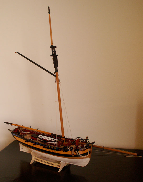
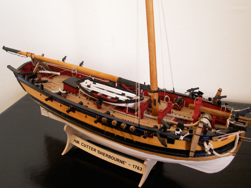
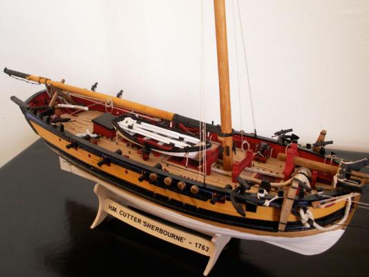
With the mastcoat in place the mast provided made for a reasonably good fit, but to aid in its location I cut a slot in its heel, which secured it over the keel piece. I then tapered the mast from about half-way up its length using a small modelling plane, being careful to take just a thin sliver off with each stroke, and finishing off with a fine-grade sandpaper. (Btw, it is important to always have a sharp blade in the plane which, I find, also tends to reduce ’catching’.) This procedure took a little while, but I didn’t want to give the mast too much of a taper – and I think it resulted in a nice-looking spar. The kit’s topgallant mast was also, to my mind, a little on the thin side and I wanted to both beef it up and lengthen it. I therefore substituted my own from a suitable piece of dowel. Both the topgallant and the lower mast were made of similar dimensions to those given for the Alert, in the AOTS book. Because of the above changes I was unable to use the ’cross trees’ and mast cap from the kit but I had decided to replace these in any case as, from my point of view, they were too small. Both parts are in fact the same, with similar-sized holes drilled for the lower mast and topgallant mast. Initially I attempted to adapt them but, when endeavouring to drill out one of the holes to enlarge it to take the head of the lower mast, it split in half – so that was that, I had to scratch them! The replacements turned out reasonably well, with separate ’trestle trees’ and ’cross trees’, into which the lower and topgallant masts fitted snugly, the lower ’cross tree’ structure resting on a pair of bibbs either side of the mast. I refer to them as ’cross trees’ and ’tressle trees’, but this is really a misnomer as they do not seem to have been fitted on cutters at this date. The structure I made more resembled an oblong-shaped ’box’, open at the top and bottom, with an off-center division passing between the two masts reflecting their differing circumferences. Cutter lower masts and topmasts were in one piece at this date, hence the separate upper mast is referred to as the topgallant. The topgallant mast was also fidded abaft, or behind, the lower mast which meant that backstays were not normally required and could therefore dispensed with. Standing and running backstays were only fitted to the lower mast. As a further historical note, Sherbourne was very likely one of the last of her type to have this masting arrangement. From around 1780, cutter masts followed the practice on larger ships, with which we are perhaps more familiar, and were rigged with a lower mast and longer topmast, complete with proper crosstrees, trestle trees, bolsters, and backstays. There are also some differences with the shrouds. On Sherbourne these terminate just above the position of the gaff (fitting over a shoulder or stop) rather than going as far as the doubling, but with the later rig the shrouds passed around the lower masthead. The number of yards and their hoisting arrangements also differ from later practice, but more about these later, except to say that pins were inserted into the masts to take the yards when fitted. The after side of the lower mast head was fitted with eyebolts to take the blocks for the throat and peak halliards and the boom topping lift, and stops were fitted in various positions for some of the rigging, such as the forestays when they they are fitted. At the base of the lower mast, I fitted a saddle around the aft side of the mast on which the boom jaws rest, whilst below them five cleats were equally spaced around the mast, to take the falls of the running rigging which might be belayed there. I’m not quite sure yet what all of these lines will be but, as I mentioned before, there is an overall lack of belaying points – so I think providing a few more will be an advantage. The cleats were painted black, as were the crosstrees, caps and masthead, whilst the mast itself was stained a reddish brown. The topgallant mast, as mentioned, was a replacement. As with the lower mast, this was carefully tapered at its upper end, and given a snug fit at the heel to fit the crosstrees and mastcap. Not immediately obvious to the eye is the fid, made made fom a small cut-off nail, which passes through a hole drilled through the heel of the mast, and which rests on the upper edges of the ’trestle trees’. As mentioned it is not that noticeable, especially as the whole assembly is painted black – but at least I know it’s there! Just below this is the sheave hole for the toprope, the rope itself being made fast to an eyebolt on the port side of the mastcap. There is a corresponding eyebolt on the starboard side, for the toprope block. At the upper end of the mast there are again stops for the rigging, and at the very top I fitted a truck. This was not provided for in the kit, but I think any mast looks unfinished without one! This was easy to make, being merely a suitably sized piece of dowel rod, with rounded edges and a small capping on the top. Four small holes, two on each side were then drilled, which will take the flag halliards when they are rigged. The topgallant mast was finished off similarly to the lower mast, with the lower end and masthead being painted black, and the spar itself being stained a reddish-brown colour. The masts were then lightly treated with beeswax. I decided to glue the topgallant mast to the lower mast before stepping them as one unit – and in the process completely forgot about how I was going to fit the mast hoops, since they would not now of course, fit over my nicely-made crosstrees! This actually didn’t prove to be such a disaster, when I gave it a little more thought, and the problem was satisfactorily resolved as I will mention later. I opted to glue the mast in place, with a smear of glue around the partners at deck level, and with a spot on the heel where it fits over the keel piece. The actual stepping of the mast went quite smoothly, and it made a close fit. To locate the cut out in the heel onto the keel piece, I had made a small pencil marks on the mast at deck level, which showed the fore and aft position. By slightly twisting the mast this way and that, as I pushed it home, I felt the heel ’lock’ in place. The mast was pretty much vertical in the athwartships plane, according to my homemade plumbob gauge, although to be sure I put some gentle pressure against the top end of the mast whilst the glue dried. The rake fore and aft was, of course, fixed by the kit design. We now come to the boom. The dimensions, from the AOTS bible, called for a spar of 62’ in length, which works out to a model length of 27.62 cm. This was not much longer than the length given in the kit instructions, but again I opted to make my own spar, it being a little thicker at 9.2 cm at it’s maximum girth. Both ends are tapered from this point, approximately a third of the length of the boom from the mast. The sides of the boom at the mast end are then chamferred, to fit the jaws. Since the kit supplied jaws would, of course, no longer fit the thicker boom (but which I otherwise considered suitable) I first split them in half, shaped the tail end to fit, and then glued them to the spar on either side. Finally, I drilled a hole in each side at the tail end of the jaws, to take a couple of belaying pins for the mainsail brails. With the boom thus shaped I painted both ends black, including the jaws, and gave it a beeswax finish. Fittings include: a preventer tackle beneath the boom, consisting of two double blocks fixed to two widely-spaced eyebolts, the fall of the line rove between them coming off of the after block, and being belayed to a small cleat on the side of the boom; two stops on top of the spar at its after end, between which the upper double sheet block strop is fastened; a sheave hole for the mainsail clew outhaul, which also belays to a small cleat on the boom; an eyebolt on top of the spar at the aft end, for the topping lift; another eyebolt, near the jaws, for the tack of the mainsail; there is also a small cleat for the ensign halliards. Having finished all these fittings, it was then time to fit the boom to the mast. The mast end would rest, and be glued to, the boom saddle and I would further secure it (as with the yards) by a pin positioned in the mast. The aft end, however, could still move if not fixed so I decided, since the sails would be furled, to make a boom crutch. I had no reference for this (other than more modern ones I have seen) so I made it out of two simple, substantial-looking cross pieces, with a pin through them where they cross. I have it in mind that they fold when not in use, and can be stowed away. It is simply glued to the deck, behind the two lockers, but it made for a stable support for the aft end of the boom. Two jobs remained to be done. The first was to fit the parrels, connecting the jaws to the mast, and here I opted to use the black parrel beads supplied with the kit. Then it was simply a case of tying a length of black rigging thread to one end of the jaws, through the hole already drilled, threading on the requisite number of beads required for it to pass comfortably around the mast (being careful not to make it too tight) and fastening the other end of the thread to the opposite jaws. A small touch of glue on the knot would prevent it from untying. There was one other small job to do before the boom was finished. I thought a small footrope at the after end, overhanging the taffrail, might look the part. This was made from a length of black rigging thread, with simple overhand knots tied at intervals, and fastened to the spar. I fitted another stop to anchor the inboard end, the outer being fastened by a simple loop over the boom. Next time: Some items of rigging, the gaff, and the mainsail.

-
Hello Adeline, So your back from Italy for a while? Good that you're able to resume work on Fly, and your first planking looks very neat. I hope you will be able to get a little more done.
-
Hi Eamon, Good for you on picking the Sherbourne! As I mentioned, she makes a nice little model, so have fun. Yes, it's always good to check the parts first to see they are all there. Sorry to hear that one of your bulkheads is missing, but hopefully your seller can resolve it. If not, perhaps you could try contacting Jotika who might supply a replacement part. Sorry, but all that I've posted is all there is. Unfortunately, I didn't start a build log from the beginning, and only began one after the hull was finished so it wouldn't have disappeared in the crash. The log, such as it is, is written in retrospect so I don't think I can help much with the early stages, even with photos – and I'm afraid my memory is not that good! I'm glad though my offerings, such as they are, have been of some help. I would suggest you check out the other logs of the MSW Sherbourne fleet, as you'll probably glean some assistance from them. Good luck.
-
John, BE, Thanks. BE, glad you're enjoying the write-ups, besides the photos.
-
Ilhan, I would say that is actually the English practice, although it may not look it due the differing angles between the photo and the drawing. Plans of the actual ship from the NMM in Greenwich plus their own expertise were, I believe, used during Endeavour's construction – and she was said to be the most accurate replica. I therefore can't imagine they would adopt Dutch shipbuilding practices.
-
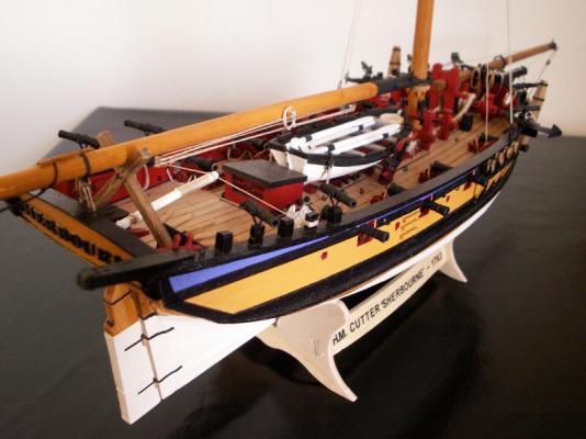
Jason, Thank you. The Sherbourne is an interesting kit and, as I mentioned earlier, is suitable both for the beginner and the more experienced builder. It certainly lends itself to further detailing and, for the builder who already has one or two models under his belt, can present something of a challenge. I think vessels like cutters often get overlooked in favour of larger ships, such as the the Victory, when they are just as interesting in their own way. The clinker planking by the way, was reasonably easy to do, but I think is effective. The below the waterline colour is actually ivory, which I thought would not be so stark. It also has the pleasing effect of making the model look rather older. If you're thinking of building her then go for it, although seeing your name, shouldn't you be constructing a model of the 'Argo'? As to your last sentence, I will endeavour to keep up the standard!
-
I am? Actually, I'm not sure that I was ever away – it's just that the latest instalment took rather longer than I anticipated – mother-in-law was visiting at the cottage! So now the blood pressure has gone down a bit (only kidding, she's lovely really and 87), perhaps we can get back to normal. Thanks for the kind words – and I have to say that I catch myself admiring the clinker planking myself, now and then!